Computer Analysis of Reinforced Concrete Walls Using FEM ... · PDF fileminimum deflection and...
6
Abstract—The paper contains an analysis of different approaches in numerical calculations of reinforced concrete walls using FEM programs for linear and non-linear models. The general introduction includes the most important issues regarding the basics of structural design. There are shown and described various ways of walls modeling which are treated as a homogenized material. The objective of this paper is a comparison of numerical analysis when using different numerical FEM programs. Depending on the capabilities of the software, it has taken into account the propagation of cracks in concrete with its impact on the whole structure. Numerical analysis shows the differences in the surface of the required reinforcement between models that take into account the minimum deflection and the acceptable width of the crack. Index Terms—RC Wall, FEM analysis, Cracks I. INTRODUCTION The aim of this paper is a numerical study of concrete walls by using different FEM programs. The analyzed structure was implemented to the following structural programs: Autodesk Robot Structural Analysis Professional and ABC Tarcza. Required reinforcement with restriction of minimum cracks were calculated in these programs. Depending on the possibilities of the used software, the analysis was performed in both a linear elastic and nonlinear range [1], [2]. As a summary, the results gained from all the programs were compared with each other and analyzed. When describing relationships between internal forces and stress in concrete and rebar steel, it is assumed that the cross-section of an RC member may be in one of the three phases. If the stresses only appear in concrete (compressive or tensile), which does not exceed compression and tensile strength, it is assumed that the element (and all of its cross- sections) is not cracked – the member is in phase I. If the member is cracked (and the ultimate limit state is not exceeded in concrete), the cracks can be observed in the cross-sections - in phase II. If the ultimate limit state was reached (internal forces reached values, which must not be exceeded) in the cross-sections of the element, it is assumed that the cross-section is in phase III. Phase I theory is used in the calculations of stresses and deflections in prestressed members and for checking stresses in some structure that are Manuscript received January 26, 2016; revised April 11, 2016. J.Baranski and J. Szolomicki are with the Wroclaw University of Technology, Wroclaw, POLAND (phone: +48 505-995-008; fax: +48 71- 322-14-65; e-mail: jerzy.szolomicki@ pwr.edu.pl) not prestressed (e.g. dynamically loaded structures). Based on phase II theory, the width of cracks and the deflections of RC members are calculated. These members are generally cracked under live load. Formerly, linear theory was used for reinforcement calculations, which were determined based on the requirement that the stresses in the reinforcement and concrete do not exceed admissible stresses. Nowadays reinforcement is generally determined based on requirements due to the ultimate limit state. Regarding the quantity of reinforcement, one of two possibilities may occur. If the amount of reinforcement in tension is moderate, the ultimate limit state of the yield strength in reinforcement is reached (failure is caused by steel). If very strong reinforcement is applied, then the failure will be caused by concrete. The yield strength in reinforcement will not be reached because, even at lower stresses, the concrete will be crushed sooner in compressed area. In the members, where a very small amount of reinforcement is applied, a situation may occur in which stresses in the reinforcement will reach yield strength directly after cracking– phase II is absent. II. LINEAR AND NON-LINEAR ANALYSIS OF A CONCRETE STRUCTURE According to EC2 [3], linear elastic analysis of elements based on the theory of elasticity may be used for both the serviceability and ultimate limit states. For the determination of the action effects, linear analysis may be carried out assuming: a) uncracked cross sections, b) a linear stress-strain relationship, c) mean values of the elastic modulus. According to [4], [5], linear analysis methods are based on classical linear elastic solutions from the scope of material strength. The main assumptions associated with the application of this method can be mentioned: linear relations − in concrete and reinforcement steel, homogeneity and isotropy of materials creating a structure, Bernoulli’s rule of plane cross sections, tension stiffening as a base of the theory of first order and the linearity of geometrical relationships. Adaptation of the linear elastic analysis method is very easy due to the possibility of using the superposition principle which exactly adds up the static effects in combinations of loads systems. This principle is that independent calculations of structure due to every kind of effect, are performed and then as a result of those effects, all Computer Analysis of Reinforced Concrete Walls Using FEM Programs J. Baranski, J. Szolomicki, Member, IAENG Proceedings of the World Congress on Engineering and Computer Science 2016 Vol II WCECS 2016, October 19-21, 2016, San Francisco, USA ISBN: 978-988-14048-2-4 ISSN: 2078-0958 (Print); ISSN: 2078-0966 (Online) WCECS 2016
Transcript of Computer Analysis of Reinforced Concrete Walls Using FEM ... · PDF fileminimum deflection and...

Abstract—The paper contains an analysis of different
approaches in numerical calculations of reinforced concrete
walls using FEM programs for linear and non-linear models.
The general introduction includes the most important issues
regarding the basics of structural design. There are shown and
described various ways of walls modeling which are treated as
a homogenized material. The objective of this paper is a
comparison of numerical analysis when using different
numerical FEM programs. Depending on the capabilities of the
software, it has taken into account the propagation of cracks in
concrete with its impact on the whole structure. Numerical
analysis shows the differences in the surface of the required
reinforcement between models that take into account the
minimum deflection and the acceptable width of the crack.
Index Terms—RC Wall, FEM analysis, Cracks
I. INTRODUCTION
The aim of this paper is a numerical study of concrete
walls by using different FEM programs. The analyzed
structure was implemented to the following structural
programs: Autodesk Robot Structural Analysis Professional
and ABC Tarcza. Required reinforcement with restriction of
minimum cracks were calculated in these programs.
Depending on the possibilities of the used software, the
analysis was performed in both a linear elastic and nonlinear
range [1], [2]. As a summary, the results gained from all the
programs were compared with each other and analyzed.
When describing relationships between internal forces and
stress in concrete and rebar steel, it is assumed that the
cross-section of an RC member may be in one of the three
phases. If the stresses only appear in concrete (compressive
or tensile), which does not exceed compression and tensile
strength, it is assumed that the element (and all of its cross-
sections) is not cracked – the member is in phase I. If the
member is cracked (and the ultimate limit state is not
exceeded in concrete), the cracks can be observed in the
cross-sections - in phase II. If the ultimate limit state was
reached (internal forces reached values, which must not be
exceeded) in the cross-sections of the element, it is assumed
that the cross-section is in phase III. Phase I theory is used
in the calculations of stresses and deflections in prestressed
members and for checking stresses in some structure that are
Manuscript received January 26, 2016; revised April 11, 2016.
J.Baranski and J. Szolomicki are with the Wroclaw University of
Technology, Wroclaw, POLAND (phone: +48 505-995-008; fax: +48 71-
322-14-65; e-mail: jerzy.szolomicki@ pwr.edu.pl)
not prestressed (e.g. dynamically loaded structures). Based
on phase II theory, the width of cracks and the deflections of
RC members are calculated. These members are generally
cracked under live load. Formerly, linear theory was used for
reinforcement calculations, which were determined based on
the requirement that the stresses in the reinforcement and
concrete do not exceed admissible stresses. Nowadays
reinforcement is generally determined based on requirements
due to the ultimate limit state. Regarding the quantity of
reinforcement, one of two possibilities may occur. If the
amount of reinforcement in tension is moderate, the ultimate
limit state of the yield strength in reinforcement is reached
(failure is caused by steel). If very strong reinforcement is
applied, then the failure will be caused by concrete. The
yield strength in reinforcement will not be reached because,
even at lower stresses, the concrete will be crushed sooner in
compressed area. In the members, where a very small
amount of reinforcement is applied, a situation may occur in
which stresses in the reinforcement will reach yield strength
directly after cracking– phase II is absent.
II. LINEAR AND NON-LINEAR ANALYSIS
OF A CONCRETE STRUCTURE
According to EC2 [3], linear elastic analysis of elements
based on the theory of elasticity may be used for both the
serviceability and ultimate limit states. For the determination
of the action effects, linear analysis may be carried out
assuming:
a) uncracked cross sections,
b) a linear stress-strain relationship,
c) mean values of the elastic modulus.
According to [4], [5], linear analysis methods are based
on classical linear elastic solutions from the scope of
material strength. The main assumptions associated with the
application of this method can be mentioned:
linear relations 𝜎−𝜀 in concrete and reinforcement steel,
homogeneity and isotropy of materials creating a
structure,
Bernoulli’s rule of plane cross sections,
tension stiffening as a base of the theory of first order and
the linearity of geometrical relationships.
Adaptation of the linear elastic analysis method is very
easy due to the possibility of using the superposition
principle which exactly adds up the static effects in
combinations of loads systems. This principle is that
independent calculations of structure due to every kind of
effect, are performed and then as a result of those effects, all
Computer Analysis
of Reinforced Concrete Walls
Using FEM Programs
J. Baranski, J. Szolomicki, Member, IAENG
Proceedings of the World Congress on Engineering and Computer Science 2016 Vol II WCECS 2016, October 19-21, 2016, San Francisco, USA
ISBN: 978-988-14048-2-4 ISSN: 2078-0958 (Print); ISSN: 2078-0966 (Online)
WCECS 2016
internal forces are added. Linear elastic analysis is also a
principle of the classic approach in the Finite Element
Method (FEM) and is currently commonly used in
conventional engineering software for the static analysis of
load bearing structures. In this method the influence of the
cross section area of the reinforcement for the moment of
inertia of a whole cross section is neglected. Assuming that a
plane stress state element is made of isotropic, linear elastic
material, the distribution of stresses depends mainly on the
geometrical dimensions of this member. Its static scheme
also includes the type of supports and the way of loading.
According to EC2 [3], nonlinear methods of analysis may be
used for both ultimate and serviceability limit states,
provided that equilibrium and compatibility are satisfied and
an adequate non-linear behavior for materials is assumed,
(Figure 1). The analysis takes into account action with and
without consideration of the effect of structural
deformations, including geometric imperfections (analysis of
first or second order). Nonlinear analysis allows a more
actual distribution of the internal forces and displacement of
the structure to be received, and also a better estimation of
its safety than the linear one. This type of analysis can be
used both for structures under external static loading and
structures under support settlement, influence of temperature
or any other extortion of static displacement. In the
structural analysis, in which the most significant is the static
loading, the influence of previous loadings and unloadings
may be neglected and monotonic increase of the considered
loading can be assumed.
Figure 1 Schematic representation of the stress-strain relations for
structural analysis [EC2].
III. BASICS OF NUMERICAL ANALYSIS
Elaboration of the solution method requires extensive
research in the range of static processes analysis of
reinforced concrete element deformations. A reinforced
concrete member is treated as a composition of materials
consisting of a spatial concrete matrix with reinforcement of
limp steel bars distributed in a discrete way in the material of
the matrix. Structural analysis is elaborated with the use of
finite element principles. Three methods of reinforcing steel
finite element modeling in a concrete matrix are known:
a discrete model,
an embedded bar model,
a smeared model.
In the discrete model, the trajectory of reinforcement bars
coincides with the concrete mesh. The concrete mesh and
reinforcement mesh have common nodal points, so concrete
is located in the same areas as the reinforcement. Some
inaccuracy of the model is a result of the fact, that the
concrete mesh is limited by the location of the reinforcement
and its small volume is not subtracted from the volume of
concrete.
In the embedded bar model, the reinforcement crosses
the grid of concrete elements, and the stiffness of steel is
determined separately in the finite element of the concrete
matrix. The method of building the model consists of
separate analyze of the displacements in the steel bar and
the concrete elements surrounding it. This technique of
modelling is beneficial for structures with a complex system
of reinforcement.
In the smeared model, layered reinforcement is assumed.
This reinforcement is uniformly distributed in the finite areas
of concrete matrix elements. This technique has an
application in oversized models of plate and shell structures
with an insignificant influence of the reinforcement on the
resistance of the structure.
Due to the behavior of a reinforced concrete structure,
cooperation between concrete and reinforcing steel is
especially important. Reinforcement bars mainly carry forces
parallel to their axis. Those forces are transferred from
concrete thanks to its bonding with steel. The main reasons
for the forming of adhesiveness are:
friction in the contact plane between steel and concrete,
chemical adhesion,
shrinkage of concrete,
in the case of ribbed reinforcement mechanical interaction
between the ribbing of the bar and concrete.
On the section between cracks the significant part of
tensile stresses is carried by concrete, and the formed
phenomenon is called the tension stiffening of concrete. In a
situation when reinforcement bars carry forces perpendicular
to their axis, and in a location where cracks resulting from
the acting of transversal forces occur in concrete, dowel
action effect can be observed.
The problem with transferring forces on reinforcement
bars which are parallel to their axis is strictly related to the
method of representing reinforcement during discretization
of the structure by using finite elements. The reinforcement
is modelled as a discrete one and uses bar elements
connected in nodes with a concrete element mesh.
Displacements which occur in a complex stress state in the
bonding stress zone are then described as the deformations
of concrete elements surrounded with nodes containing
reinforcement. As a result of bonding at sections between
cracks, reinforcement bars transfer a significant part of the
tensile stresses on concrete. This phenomenon results in a
global increase of reinforced concrete structures. A
commonly used method of including this tensioning effect is
the assumption of a gradual decrease of the tensile strength
of a structure due to concrete failure. The characteristics of
what the function of concrete degradation in the tensile zone
should have are yet to be agreed upon. It seems to be
reasonable that the solution to this problem requires
Proceedings of the World Congress on Engineering and Computer Science 2016 Vol II WCECS 2016, October 19-21, 2016, San Francisco, USA
ISBN: 978-988-14048-2-4 ISSN: 2078-0958 (Print); ISSN: 2078-0966 (Online)
WCECS 2016

calibration of the model and a comparison of the numerical
analysis results with experimental research results.
In most cases encountered in practice in a structure’s
mechanical range, the Newton-Raphson method is used to
solve the systems of equations [1],[2].
.} {=}]{[ aFuK (1)
Where:
[𝐾] −the matrix of the system coefficients,
{u} – the wanted vector of generalized displacement in three
perpendicular directions,
{Fa}– the known vector of generalized loading.
The equation (1) is non-linear, because the matrix of the
system coefficients [𝐾] is a function or derivative of the
searched values of generalized displacements in three
perpendicular directions. The Newton-Raphson method is an
iterative process of solving nonlinear equations in the
forms:
[𝐾𝑖𝑇]{∆𝑢𝑖} = {𝐹𝑎} − {𝐹𝑖
𝑛𝑟}, (2)
{𝑢𝑖+1} = {𝑢𝑖} + {∆𝑢𝑖}, (3)
where:
[KiT]– the matrix of tangent stiffness,
i– the index corresponding with number of incremental step,
{Finr} – the vector of internal nodal forces corresponding
with the stress state occurring in a discretizing system.
This method works perfectly for materials with linear-
elastic characteristics. However, according to non-linear
materials, after the cracking and crushing application, it is
not as effective. Its disadvantage is the necessity of reversing
the new stiffness matrix during every iteration stage and
what is even more important, the lack of possibility to
describe the mechanism of material failure, because the
solution is not converged at the moment of zeroing out the
stiffness matrix. The reflection of eventual structure
degradation, visible on a load-displacement curve as sharp
drops of loading, is only possible with the use of far more
complex iteration methods in comparison to the Newton-
Raphson method. In order to achieve a complete path of
load-deformation showing both local and global degradation
of a structure and a description of failure mechanism, two
effective methods can be used:
the modified Newton-Raphson method,
the arc-length Crisfield’s method.
The modified Newton-Raphson method consists of changing
the solution path near the limit point and moving backwards
along the secant until a fast numerical solution convergence
achieved [1]. The stiffness matrix in comparison to Newton-
Raphson (eq. 1) is described as a sum of two matrixes:
[𝐾𝑖𝑇] = 𝜉[𝐾𝑠] + (1 − 𝜉)[𝐾𝑇], (4)
where:
[𝐾𝑠]– the matrix of secant stiffness,
[𝐾𝑇]– the matrix of tangent stiffness,
ξ – the parameter of adaptation decrease.
This method consists of coordination of the adaptation of the
decrease parameter 𝜉 during the equilibrium iteration. The
matrix of secant stiffness is generated in the numerical
method as a result of solving nonlinear issues according to:
yielding of the material,
stiffness of the structure with big displacements,
crushing the concrete with relaxation stresses after
cracking taken into account.
In the numerical arc-length (Crisfield’s) method, equation is
dependent on the loading of parameter 𝜆:
[𝐾𝑖𝑇]{𝑢𝑖} = 𝜆{𝐹𝑎} − {𝐹𝑖
𝑛𝑟}. (5)
In this method, variable loading parameter 𝜆 searched in
equilibrium equations is from the range ⟨−1,1⟩.
The equation in the intermediate step of loading is in the
form:
[𝐾𝑖𝑇]{Δui} − Δ𝜆{𝐹𝑎} = (𝜆0 + Δ𝜆𝑖){𝐹𝑎} − {𝐹𝑖
𝑛𝑟}, (6)
where:
Δ𝜆 - the parameter of loading increment.
Based on equation (6), the searched vector of displacement
increment {Δui} composed of two components is described
as:
{𝑢𝑖} = Δ𝜆{𝑢𝑖𝐼} + {𝑢𝑖
𝐼𝐼}, (7)
where:
{uiI} – the vector of displacement increment induced be
unitary parameter of loading,
{uiII} – the vector of displacement increment in Newton-
Raphson method.
IV. NUMERICAL ANALYSIS
In order to compare the results receiving from different
software using FEM, an identical model of the wall was
implemented in all programs, (Figure 2). The model is a
simply supported deep-beam with two symmetrical openings
implemented. It was modeled as a shell structure working as
a plane stress state element in a two dimensional coordinate
system. All loads act only in the plane of the wall. In the
nearest surrounding of the connection between the wall and
a support, an accumulation of stresses can occur. This is the
reason why finite elements should be placed in such places.
In numerical analysis the following was assumed:
Dimensions: height of the whole element: 3.0m, length of
the whole element: 7.0m, length of the supported columns:
0.7m, length of the span: 5.6m, dimensions of the openings:
1.0 m x 1.2m; constant thickness of the wall: 0.25m.
Materials: concrete: C25/30, reinforcing steel: AIIIN
(B500SP).
Loads:
the self-weight, uniformly distributed load applied along the
top of the deep- beam, the magnitude of the load: 300kN/m.
Figure 2 Basic dimensions and finite elements mesh
Proceedings of the World Congress on Engineering and Computer Science 2016 Vol II WCECS 2016, October 19-21, 2016, San Francisco, USA
ISBN: 978-988-14048-2-4 ISSN: 2078-0958 (Print); ISSN: 2078-0966 (Online)
WCECS 2016

1. Numerical analysis by means of Robot Structural
Analysis Professional 2015
There are two available methods for the reinforcement of a
wall determined in Robot software:
The Analytical method
If the reinforcement values 𝐴𝑥 and 𝐴𝑦(corresponding to
two perpendicular directions 𝑥 and 𝑦) are given, an
equivalent reinforcement in any other direction (𝑛) is
calculated according to the following formula:
𝐴𝑛 = 𝐴𝑥𝑐𝑜𝑠2(𝛼) + 𝐴𝑦𝑠𝑖𝑛2(𝛼), (8)
where:
𝛼 - the angle included between direction 𝑥 and direction 𝑛.
The values of sectional forces (membrane forces) 𝑁𝑛 may be
obtained from the following transformational formula:
𝑁𝑛 = 𝑁𝑥𝑐𝑜𝑠2(𝛼) + 𝑁𝑦𝑠𝑖𝑛2(𝛼) − 𝑁𝑥𝑦𝑠𝑖𝑛2(2𝛼). (9)
Thus, the below-presented inequality formulates the
condition of correct reinforcement. The reinforcement that is
able to carry the internal forces in an arbitrary section:
𝐴𝑥𝑐𝑜𝑠2(𝛼) + 𝐴𝑦𝑠𝑖𝑛2(𝛼) ≥ Φ(𝑁𝑛), (10)
where:
Φ(Nn)- refers to the value of reinforcement required to
carry the forces calculated for the direction ' 𝑛 ' - Φ(Nn).
This determines on the plane (𝐴𝑥, 𝐴𝑦) the area of
'admissible' values of reinforcement Ax and Ay (half-plane).
If such an area is determined for a sufficiently "dense" set of
directions 𝑛 (control is performed every 10), one obtains the
area of admissible values Ax and Ay. The adopted
reinforcement is the minimal reinforcement which yields the
minimal sum of surfaces Ax + Ay.
The Wood&Armer method
Design forces are calculated according to the method by
Wood and Armer from the formulas given below for a plane
stress structure or for the activated option of panel design for
compression/ tension in a shell structure. For the selected
directions 𝑥 and 𝑦, two types of design forces 𝑁* are
calculated:
the tensile (positive, causing main tension in a section),
the compressive (negative, causing section compression).
The general procedure takes the following form:
Calculation of 'tensile' forces Nxr,* Nyr
*
𝑁𝑥𝑟∗ = 𝑁𝑥 + |𝑁𝑥𝑦|, (11)
𝑁𝑦𝑟∗ = 𝑁𝑦 + |𝑁𝑥𝑦|. (12)
However if Nx < -|Nxy| (i.e. calculated Nxr* < 0),
𝑁𝑥𝑟∗ = 0, (13)
𝑁𝑦𝑟∗ = 𝑁𝑦 + |𝑁𝑥𝑦 ∙
𝑁𝑥𝑦
𝑁𝑥|. (14)
Similarly, if Ny < -|Nxy |(i.e. calculated Nyr* < 0),
𝑁𝑦𝑟∗ = 0, (15)
𝑁𝑥𝑟∗ = 𝑁𝑥 + |𝑁𝑥𝑦 ∙
𝑁𝑥𝑦
𝑁𝑥|. (16)
If any of the obtained forces Nxr* , Nyr
* are less than zero,
one should assume a zero value (forces determined when
designing a section by reinforcement compression are
determined further on).
Calculation of 'compressive' forces Nxs,* Nys
*
𝑁𝑥𝑠∗ = 𝑁𝑥 − |𝑁𝑥𝑦|, (17)
𝑁𝑦𝑠∗ = 𝑁𝑦 − |𝑁𝑥𝑦|. (18)
However, if Nx > |Nxy|(i.e. calculated Nxs* > 0),
𝑁𝑥𝑠∗ = 0, (19)
𝑁𝑦𝑠∗ = 𝑁𝑦 − |𝑁𝑥𝑦 ∙
𝑁𝑥𝑦
𝑁𝑥|. (20)
Similarly, if Ny > |Nxy|(i.e. calculated Nys* > 0),
𝑁𝑦𝑠∗ = 0, (21)
𝑁𝑥𝑠∗ = 𝑁𝑥 − |𝑁𝑥𝑦 ∙
𝑁𝑥𝑦
𝑁𝑦|. (22)
If any of the obtained forces 𝑁𝑥𝑠∗ , 𝑁𝑦𝑠
∗ is greater than zero,
one should assume a zero value (such forces are determined
when designing a section by reinforcement tension, which is
already guaranteed by the tensile forces 𝑁𝑥𝑟∗ , 𝑁𝑦𝑟
∗ calculated
earlier).
Figure 3 Required area of reinforcement in XX direction with a restriction
of minimum crack width (0,2 mm) ROBOT) [mm2/m]
Figure 4 Required area of reinforcement in YY direction with a restriction
of minimum crack width (0,2 mm) (ROBOT) [mm2/m]
The width of cracking is calculated independently for two
directions. They are defined by axes of reinforcement. The
algorithm of calculations is based on the formulas enabling
calculation of the cracking width for beam elements.
Calculations are carried out on the cross-section with
reinforcement resulting from the Ultimate Limit State.
Moments recognized in calculations of the Serviceability
Limit State are equivalent moments calculated according to
the selected calculation method: Analytical or Wood
&Armer. When reinforcement adjustment is selected for
calculations, the area of reinforcement undergoing tension
increases, reducing the cracking width. When it is not
possible to fulfil the user-defined condition of the maximum
cracking width, the table of results will highlight the result
cell in red. There are no non-code limits set on the
reinforcement ratio, so attention should be paid to the
economic aspect of the solution provided.
Proceedings of the World Congress on Engineering and Computer Science 2016 Vol II WCECS 2016, October 19-21, 2016, San Francisco, USA
ISBN: 978-988-14048-2-4 ISSN: 2078-0958 (Print); ISSN: 2078-0966 (Online)
WCECS 2016
2. Numerical analysis using ABC Tarcza
According to the algorithm presented in EC2 [3] is assumed
that cracks may appear in plane stress state element
locations. All existing tensile and shearing forces in the
plane stress state element must be carried by the
reinforcement. Concrete only carries the compressive
stresses. In every point of the plane stress state element, σx,
σy and τxy should be determined. It is assumed, that tensile
stresses are treated as positive. For positive values of 𝑓𝑡𝑑𝑥
and 𝑓𝑡𝑑𝑦, the required reinforcement is determined from
following equations:
horizontal:
Asx =ftdx
fydh , (23)
vertical:
Asy =ftdy
fydh , (24)
where:
ℎ – the thickness of the wall,
𝐴𝑠𝑥 - the cross section area of rebars in a horizontal
direction,
𝐴𝑠𝑦 - the cross section area of rebars in a vertical direction.
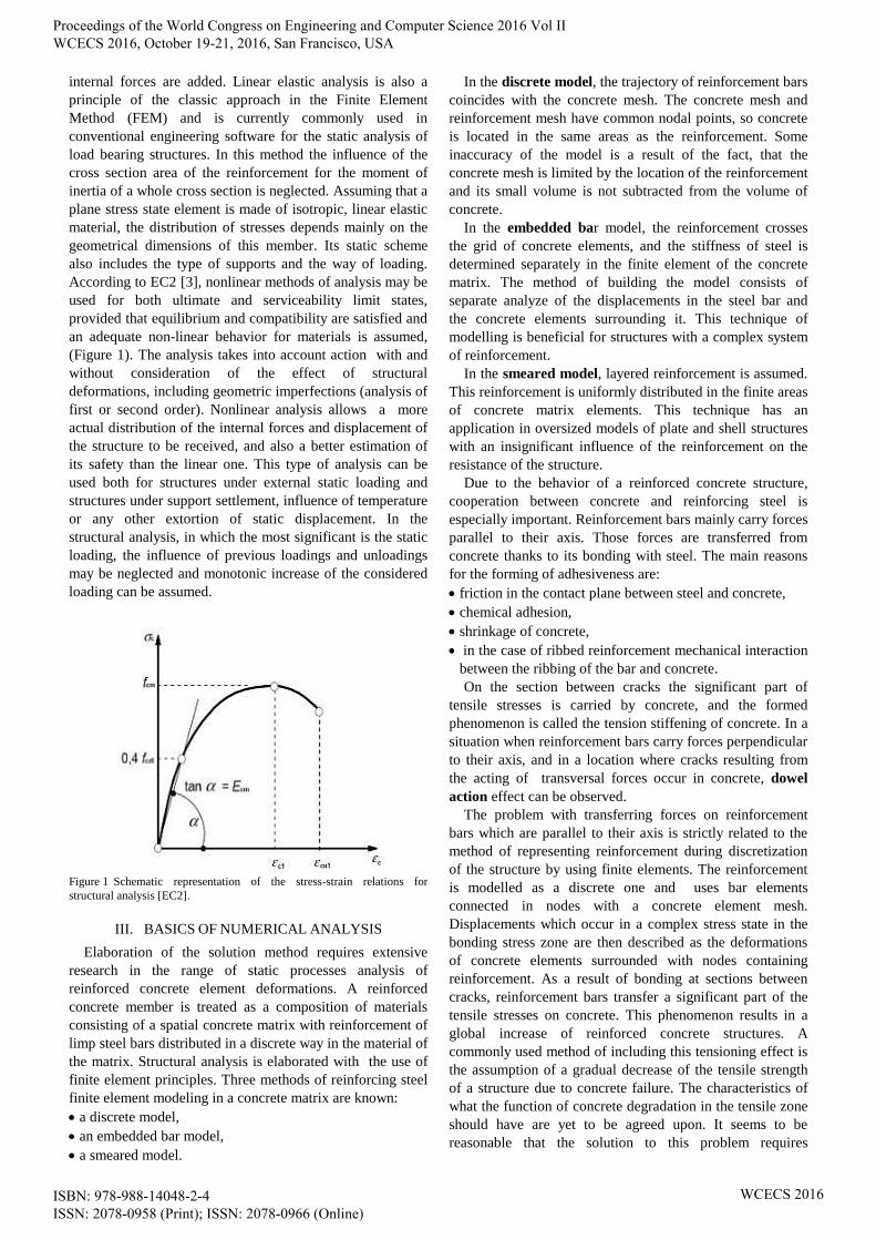
Figure 5 Required area of reinforcement in XX direction with a restriction
of minimum crack width (0,2 mm)(ABC Tarcza) [mm2/m]
Figure 6 Required area of reinforcement in XX direction with a restriction
of minimum crack width (0,2 mm)(ABC Tarcza) [mm2/m]
The method used for determining the crack width in the
ABC Tarcza program may be directly derived from standard
equations for the sections under axial tension. However,
there is not always compatibility between the directions of
principal stresses and the directions of reinforcement. This
fact directly affects the spacing of the cracks. The spacing
of the cracks was determined using the following equation:
𝑠𝑟𝑚,𝑚𝑎𝑥 = 𝑠𝑟𝑚𝑥 ∙ 𝑐𝑜𝑠 (2𝜋𝜃
360)
𝑛
+ 𝑠𝑟𝑚𝑦 ∙ 𝑠𝑖𝑛 (2𝜋𝜃
360)
𝑛
.
(25)
The width of the cracks, determined in such way, may be
considered as correct when the directions of principal tensile
stresses are roughly the same as the directions of
reinforcement. In general, when angle 𝜃 exists between the
principal direction 𝜎1 and the reinforcement in 𝑥 direction,
the width of the crack in direction of 𝜎1stress and in case of
σ1 ≥ fctm was determined from the following equation:
𝑤1 = 𝑤𝑥 ∙ 𝑐𝑜𝑠 (2𝜋90+𝜃
360)
3
+ 𝑤𝑦 ∙ 𝑠𝑖𝑛 (2𝜋90+𝜃
360)
3
.
(26)
The width of the cracks in direction of σ2 stress and in case
of σ2 ≥ fctmwas determined from the following equation:
𝑤2 = 𝑤𝑥 ∙ 𝑐𝑜𝑠 (2𝜋90+𝜃
360)
3
+ 𝑤𝑦 ∙ 𝑠𝑖𝑛 (2𝜋90+𝜃
360)
3
.
(27)
If during the analysis appear intersecting cracks, the program
shows always higher value calculated from equations (25)
and (26).
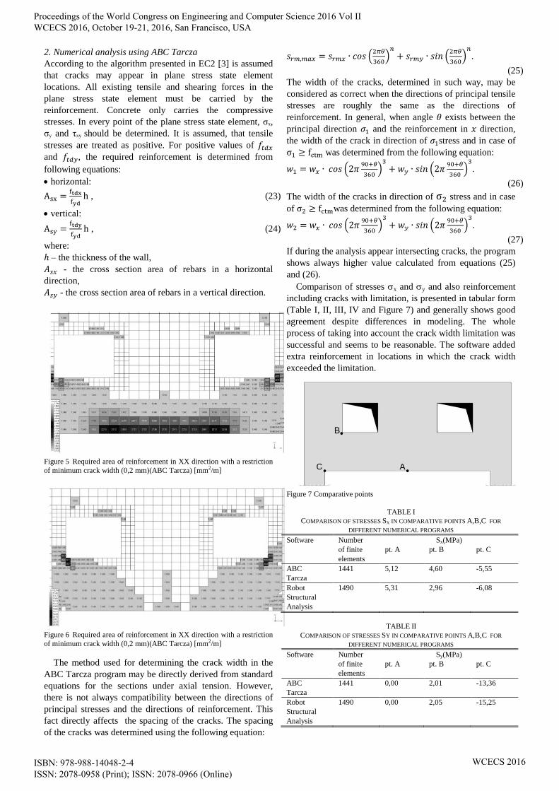
Comparison of stresses x and y and also reinforcement
including cracks with limitation, is presented in tabular form
(Table I, II, III, IV and Figure 7) and generally shows good
agreement despite differences in modeling. The whole
process of taking into account the crack width limitation was
successful and seems to be reasonable. The software added
extra reinforcement in locations in which the crack width
exceeded the limitation.
Figure 7 Comparative points
TABLE I
COMPARISON OF STRESSES SX IN COMPARATIVE POINTS A,B,C FOR
DIFFERENT NUMERICAL PROGRAMS
Software Number
of finite
elements
Sx(MPa)
pt. A pt. B pt. C
ABC
Tarcza
1441 5,12 4,60 -5,55
Robot
Structural
Analysis
1490 5,31 2,96 -6,08
TABLE II
COMPARISON OF STRESSES SY IN COMPARATIVE POINTS A,B,C FOR
DIFFERENT NUMERICAL PROGRAMS
Software Number
of finite
elements
Sy(MPa)
pt. A pt. B pt. C
ABC
Tarcza
1441 0,00 2,01 -13,36
Robot
Structural
Analysis
1490 0,00 2,05 -15,25
Proceedings of the World Congress on Engineering and Computer Science 2016 Vol II WCECS 2016, October 19-21, 2016, San Francisco, USA
ISBN: 978-988-14048-2-4 ISSN: 2078-0958 (Print); ISSN: 2078-0966 (Online)
WCECS 2016

TABLE III
COMPARISON OF REINFORCEMENTS AX IN COMPARATIVE POINTS A,B,C FOR
DIFFERENT NUMERICAL PROGRAMS
Software Number
of finite
elements
Ax(cm2/m)
pt. A pt. B pt. C
ABC
Tarcza
1441 18,51 14,70 Ax,min
Robot
Structural
Analysis
1490 16,77 13,56 Ax,min
TABLE IV
COMPARISON OF REINFORCEMENTS AY IN COMPARATIVE POINTS A,B,C FOR
DIFFERENT NUMERICAL PROGRAMS
Software Number
of finite
elements
Ay(cm2/m)
pt. A pt. B pt. C
ABC
Tarcza
1441 Ay,min 10,33 -6,70
Robot
Structural
Analysis
1490 Ay,min 8,76 -6,72
V. CONCLUSIONS
The study deals with the numerical calculations of
reinforced concrete walls using FEM programs considering
linear and nonlinear models. This paper presents the general
principals of structural design and briefly describes linear
and nonlinear types of analysis. Very important is the
description of the cracked concrete phenomenon, basics of
numerical analysis, touching such topics as reinforced
concrete models, cooperation between concrete and
reinforcing steel, numerical methods of solving systems of
equilibrium equations, implementation of finite element
system and finally, the nonlinear analysis algorithm. The
most common numerical methods have been presented:
The Newton-Raphson method,
The modified Newton-Raphson method,
The Arc-length (Crisfield’s) method.
The main aim of this paper is the analysis of the
calculation methods applied in the designing of a simple
reinforced concrete wall with a restriction of minimum
cracks and deflections and also comparison of the results of
the analysis. A one static scheme with two symmetrical
openings, which represents an actual reinforced wall in quite
good way, was chosen for the analysis. The numerical
calculations of this structure were performed using the
following FEM software:
Robot Structural Analysis Professional 2015,
ABC Tarcza 6.15.
In the two used software programs (Robot, ABC Tarcza),
the results of principal stresses and the required
reinforcement were close to each other. However, some
differences occur in the corners of the openings, where the
stresses reach maximum values. This phenomenon may be
caused by different implementation of peak smoothing of
stresses in each software program. The settings of this option
are generally treated in a very simplified way. Because of
this fact, the peak smoothing is hard to control, which may
result in such inaccuracies. Moreover, the differences
occurred with crack width calculations because of
differences in the methods applied in different programs.
This observation may lead to the conclusion that the crack
width calculation in this kind of software should be done
very carefully during the design stage. Although all the used
programs can analyze cracked concrete in some way, we
cannot treat the results as an actual response of the RC
structure, but only as a general view of localization and the
width of cracks.
REFERENCES
[1] M.M. Kjell, “Solution methods for non-linear FEA”, Norwegian
University of Science and Technology, 2012.
[2] P. Wrigger, “Nonlinear Finite Element Methods”, Springer
Science&Business Media, 2008.
[3] [EC2] PN-EN 1992-1-1 Design of concrete structure – Part 1:
General rules and rules for buildings.
[4] F.K. Kong, “Reinforced concrete deep beams”, Taylor&Francis e-
Library 2002.
[5] A. Łapko, J.B. Christian, “Fundamentals of design and algorithms for
the calculation of RC structures” (written in polish), Arkady,
Warsaw,Poland, 2005.
Proceedings of the World Congress on Engineering and Computer Science 2016 Vol II WCECS 2016, October 19-21, 2016, San Francisco, USA
ISBN: 978-988-14048-2-4 ISSN: 2078-0958 (Print); ISSN: 2078-0966 (Online)
WCECS 2016