Computer aided ergonomics design of automobiles · Computer aided ergonomics design of automobiles...
37
•
Transcript of Computer aided ergonomics design of automobiles · Computer aided ergonomics design of automobiles...
Loughborough UniversityInstitutional Repository
Computer aided ergonomicsdesign of automobiles
This item was submitted to Loughborough University's Institutional Repositoryby the/an author.
Citation: PORTER, J.M. ... et al, 1993. Computer aided ergonomics de-sign of automobiles. IN: Peacock, B. and Waldemar, K. (eds). AutomotiveEngineering. London: Taylor and Francis, pp. 43 - 77
Additional Information:
• This is a chapter from the book Automotive Ergonomics [ c© Taylor andFrancis].
Metadata Record: https://dspace.lboro.ac.uk/2134/14269
Version: Accepted for publication
Publisher: c© Taylor and Francis
Please cite the published version.

This item was submitted to Loughborough’s Institutional Repository (https://dspace.lboro.ac.uk/) by the author and is made available under the
following Creative Commons Licence conditions.
For the full text of this licence, please go to: http://creativecommons.org/licenses/by-nc-nd/2.5/
In B. Peacock, & W. E. Karwowski (Eds.), Automotive Ergonomics (pp. 43-77). London: Taylor and Francis, 1993.
Published in Ergonomics Abstracts, No 135351, 1993.
Computer-aided ergonomics design of automobiles
J. M. Porter, K. Case, M. T. Freer and M. C. Bonney
Computer-aided design and the design process Computer-aided design (CAD) can refer to any kind of activity which utilizes a computer to assist in the creation, modification, presentation and analysis of a design (Majchrzak et al., 1987). Groover and Zimmers (1984) present a useful, although greatly simplified, overview of the typical design process showing the contributions of both the designers and the CAD system during the main phases of design (see Figure 3.1).
Many manufacturing companies were first introduced to CAD because it is a means of rapidly producing and modifying engineering drawings for detail design. While this ‘electronic drawing board' approach has been a relatively painless introduction to CAD, it is only the tip of the iceberg in terms of the functionality potentially available to the design team (i.e. engineers, stylists, ergonomists etc.). The aerospace industry has led the way since the early 1970s in using CAD as a design analysis tool for the representation of complex three-dimensional shapes and for the production of manufacturing information. The automotive industry has similarly undergone a transformation to the extent that one major British manufacturer has the stated intentions of performing all design work using three-dimensional systems and of requiring all its suppliers to have the facility to receive 'drawings' in electronic form. Similarly, the electronics industry is probably the leader in the use of its own products for the design, simulation of operation, manufacture, assembly and testing of new products.
In mechanical design great strides have been made in providing the link between design (CAD) and manufacture (CAM), often referred to as CAD/CAM. For example, it is often possible to extract geometric information from a CAD system and pass it to a CAM system for the addition of machining information before post-processing and transmission to the machine tool.
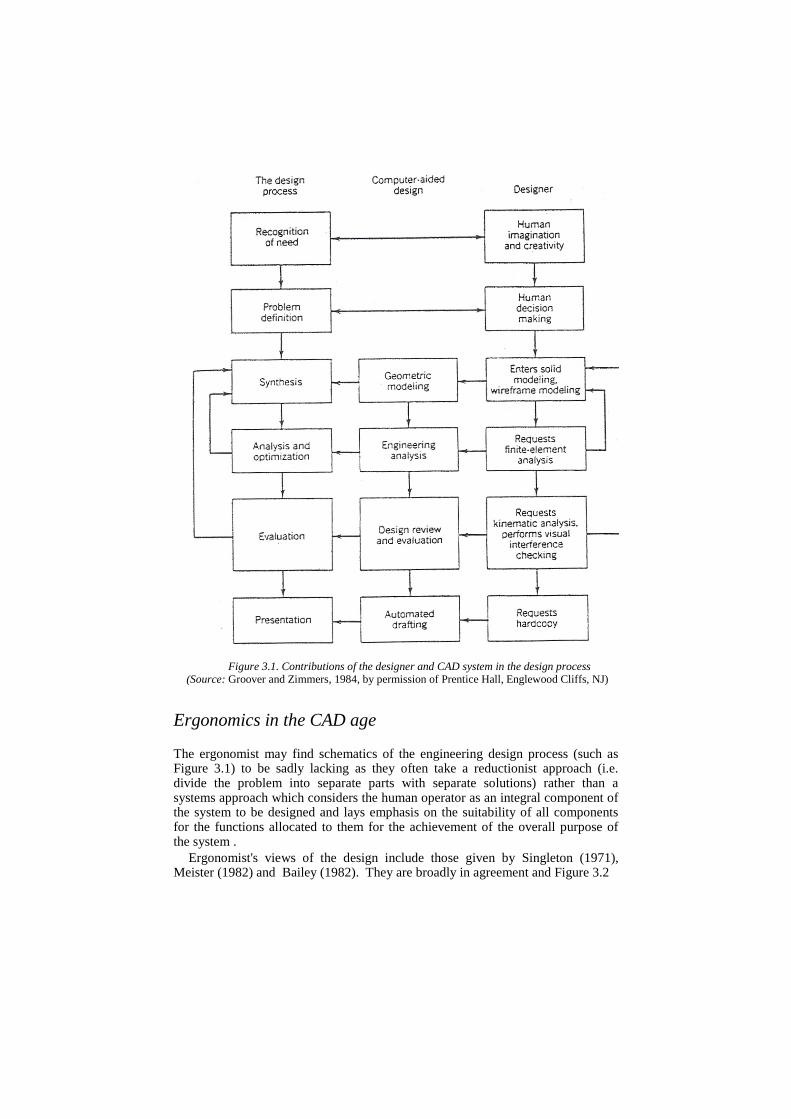
Figure 3.1. Contributions of the designer and CAD system in the design process
(Source: Groover and Zimmers, 1984, by permission of Prentice Hall, Englewood Cliffs, NJ)
Ergonomics in the CAD age The ergonomist may find schematics of the engineering design process (such as Figure 3.1) to be sadly lacking as they often take a reductionist approach (i.e. divide the problem into separate parts with separate solutions) rather than a systems approach which considers the human operator as an integral component of the system to be designed and lays emphasis on the suitability of all components for the functions allocated to them for the achievement of the overall purpose of the system .
Ergonomist's views of the design include those given by Singleton (1971), Meister (1982) and Bailey (1982). They are broadly in agreement and Figure 3.2
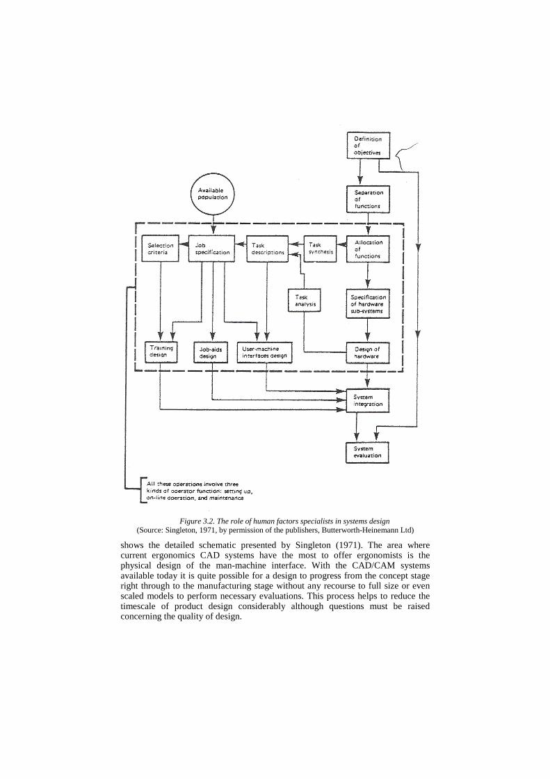
Figure 3.2. The role of human factors specialists in systems design (Source: Singleton, 1971, by permission of the publishers, Butterworth-Heinemann Ltd)
shows the detailed schematic presented by Singleton (1971). The area where current ergonomics CAD systems have the most to offer ergonomists is the physical design of the man-machine interface. With the CAD/CAM systems available today it is quite possible for a design to progress from the concept stage right through to the manufacturing stage without any recourse to full size or even scaled models to perform necessary evaluations. This process helps to reduce the timescale of product design considerably although questions must be raised concerning the quality of design.
Traditionally, products were created by craftsmen who, as individuals, were responsible for the design and manufacture of their products, for example chairs, shoes and musical instruments. These craftsmen could modify their basic design to meet the needs for each new customer. For example, a chair could be made wider and lower to suit a short and heavy customer. If problems arose with a particular design, either in manufacture or use, then the craftsmen would receive swift feedback and be able to make any necessary modifications. In this way the design was often seen to evolve or become more 'finely tuned' to the needs of the end user or customer. With advent of CAD/CAM systems there is a risk that this evolutionary aspect of product design will suffer because the feedback from the end users will not be available until after the product's design and manufacture have been finalized. A successful design needs to find the optimum compromises within the variety of constraints that are imposed upon it from the financial, legislative, engineering, styling, manufacturing and end users' viewpoints. Unfortunately, most CAD/CAM systems provide little or no information concerning the needs of the end user and there is considerable danger that design decisions are only made to satisfy the other more tangible engineering and financial constraints. This can result in decisions which the customer finds unsatisfactory. For example, why do many car manufacturers force their customers to adopt a twisted posture when driving by placing the seat, steering wheel and pedals out of line with the straight ahead position? Why do these manufacturers actually design out a significant percentage of their potential customers by not allowing sufficient headroom or set and steering wheel adjustment? If problems such as these are evident now with cars that were designed before the advent of CAD/CAM then there must be worries for the future. If a major advantage of CAD/CAM is to reduce the timescale of product design then the costly and time-consuming process of constructing mock-ups will certainly decline. There is a danger that the ergonomics input will then take the form of working to approved guidelines and meeting legislation, both of which do not necessarily result in the optimum design.
It is essential that the ergonomics input to a product takes place throughout the design process but nowhere is it more important than at the concept and early development stages of design. Basic ergonomics criteria such as the adoption of comfortable and effective postures need to be satisfied very early on. If these criteria are not thoroughly assessed then there is usually only very limited scope for modifications later on as all the other design team members will have progressed too far to make major changes without considerable financial and time penalties.
The ideal solution to help ensure that the finished product meets the ergonomics requirements is to conduct the traditional mock-up stage using computer graphics. A prerequisite of this possibility is that we can successfully model the end user to a satisfactory level of accuracy.
In the concept stage the design team will need mainly dimensional information describing the future users' needs based upon the variation of body size and postures which will be adopted to meet the task requirements and to maximize comfort. The computer modeling of people (known as 'man modeling') therefore needs to include anthropometric variation and to permit the postural evaluation of workstations based upon criteria related to fit, reach, vision and comfort. Such man-modeling CAD systems exist and, in some cases, have existed since the late
1960s well before the advent of CAD/ CAM. Brennan and Fallon (1990) consider that such CAD systems greatly enhance the
abilities of the ergonomist and have the potential to place the ergonomist in a more directive, as opposed to supportive, role in the system design process.
Man-modeling CAD systems A wide variety of such systems have been developed. Their functionality, flex-ibility and success have also varied considerably. Kinematic modeling enables the spatial evaluation of workplaces where either the human operator or parts of the physical environment are placed in different positions over time - the type of modeling which is the focus of this chapter. In order to represent these spatial relationships the man model needs to be suitably 'enfleshed', preferably using solid modeling as this allows evaluative features such as hidden lines or interference checking between two solids in three-dimensional space. Kinetic, or dynamic, modeling is usually associated with assessing the body's response to large external forces such as those experienced in car crash simulations. In this type of modeling more consideration may be given to body segment parameters such as mass, center of gravity and moments of inertia.
Descriptions of the earlier kinematic systems (i.e. BOEMAN, BUFORD, CAR, COMBIMAN, CYBERMAN and SAMMIE) are given in the review papers by Dooley (1982) and Rothwell (1985) and most of the currently available systems (i.e. COMBIMAN, CREW CHIEF, ErgoSHAPE, ErgoSPACE, MINT AC, SAMMIE, TADAPS and WERNER) are presented in Karwowski et al., (1990). Other systems include FRANKY and ANYBODY. Brief details of each system are presented below.
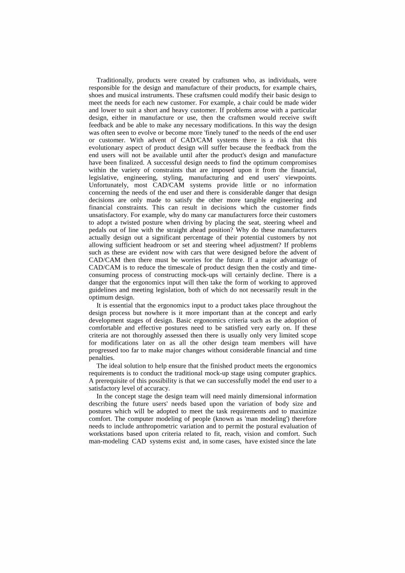
ANYBODY (see Figure 3.3) is a three-dimensional ergonomics template or stencil of the human form which is used in conjunction with the CADKEY workplace modeling system which can run on an IBM AT. It is marketed by IST GmbH in Germany. The templates are available for men and women in a variety of sizes (females: fifth and 50th percentiles; males: 50th and 95th percentiles) and shapes (ectomorph, mesomorph and endomorph). The anthropometric data are taken from DIN 33402 part 2 which presents information for the German public although 50th percentile models are available for other databases such as those presented in Bodyspace (Pheasant, 1986). The developers suggest that these templates can be linearly scaled to represent other body dimensions. No published studies on the development or application of ANYBODY have been found.
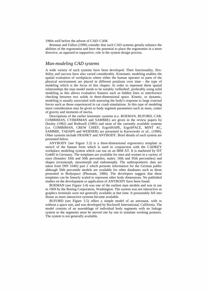
BOEMAN (see Figure 3.4) was one of the earliest man models and was in use in 1969 by the Boeing Corporation, Washington. The system was not interactive as graphics terminals were not generally available at that time. It presumably fell into disuse as more interactive systems became available.
BUFORD (see Figure 3.5) offers a simple model of an astronaut, with or without a space suit, and was developed by Rockwell International, California. The model consists of an assemblage of individual body segments with no linkage system so the segments must be moved one by one to simulate working postures. The system is not generally available.
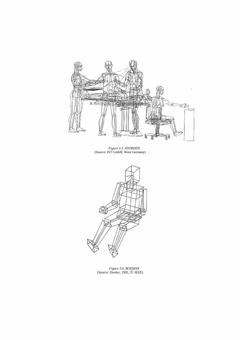
Figure 3.3. ANYBODY (Source: IST GmbH, West Germany)
Figure 3.4. BOEMAN (Source: Dooley, 1982, © IEEE)
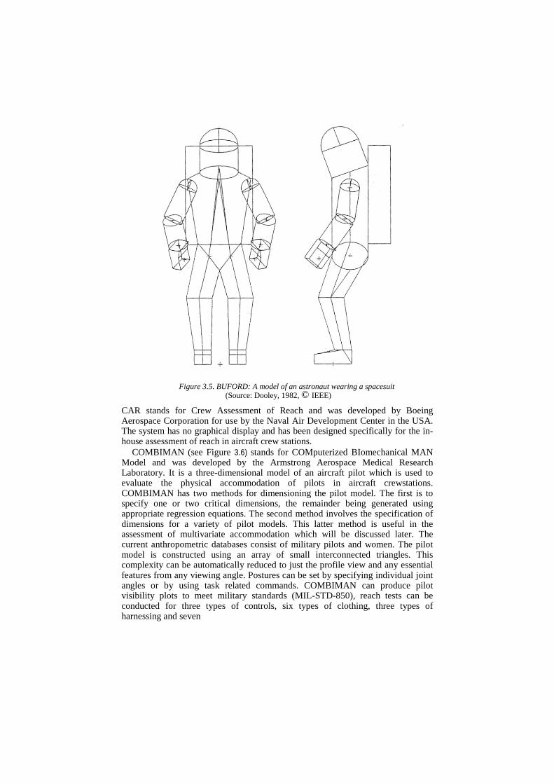
Figure 3.5. BUFORD: A model of an astronaut wearing a spacesuit (Source: Dooley, 1982, © IEEE)
CAR stands for Crew Assessment of Reach and was developed by Boeing Aerospace Corporation for use by the Naval Air Development Center in the USA. The system has no graphical display and has been designed specifically for the in-house assessment of reach in aircraft crew stations.
COMBIMAN (see Figure 3.6) stands for COMputerized BIomechanical MAN Model and was developed by the Armstrong Aerospace Medical Research Laboratory. It is a three-dimensional model of an aircraft pilot which is used to evaluate the physical accommodation of pilots in aircraft crewstations. COMBIMAN has two methods for dimensioning the pilot model. The first is to specify one or two critical dimensions, the remainder being generated using appropriate regression equations. The second method involves the specification of dimensions for a variety of pilot models. This latter method is useful in the assessment of multivariate accommodation which will be discussed later. The current anthropometric databases consist of military pilots and women. The pilot model is constructed using an array of small interconnected triangles. This complexity can be automatically reduced to just the profile view and any essential features from any viewing angle. Postures can be set by specifying individual joint angles or by using task related commands. COMBIMAN can produce pilot visibility plots to meet military standards (MIL-STD-850), reach tests can be conducted for three types of controls, six types of clothing, three types of harnessing and seven
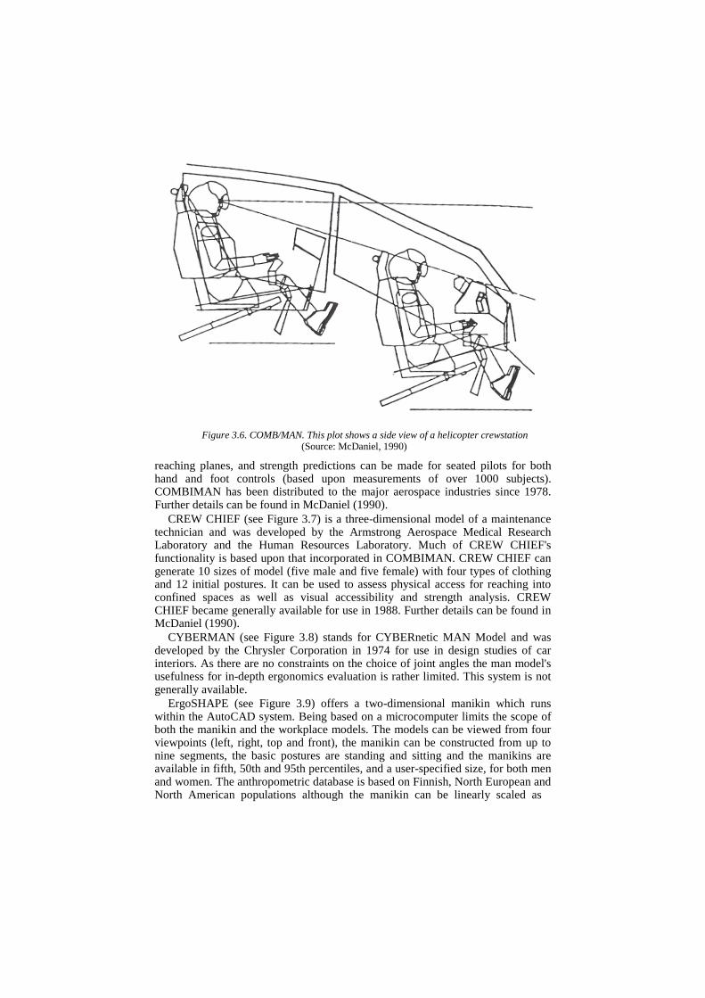
Figure 3.6. COMB/MAN. This plot shows a side view of a helicopter crewstation (Source: McDaniel, 1990)
reaching planes, and strength predictions can be made for seated pilots for both hand and foot controls (based upon measurements of over 1000 subjects). COMBIMAN has been distributed to the major aerospace industries since 1978. Further details can be found in McDaniel (1990).
CREW CHIEF (see Figure 3.7) is a three-dimensional model of a maintenance technician and was developed by the Armstrong Aerospace Medical Research Laboratory and the Human Resources Laboratory. Much of CREW CHIEF's functionality is based upon that incorporated in COMBIMAN. CREW CHIEF can generate 10 sizes of model (five male and five female) with four types of clothing and 12 initial postures. It can be used to assess physical access for reaching into confined spaces as well as visual accessibility and strength analysis. CREW CHIEF became generally available for use in 1988. Further details can be found in McDaniel (1990).
CYBERMAN (see Figure 3.8) stands for CYBERnetic MAN Model and was developed by the Chrysler Corporation in 1974 for use in design studies of car interiors. As there are no constraints on the choice of joint angles the man model's usefulness for in-depth ergonomics evaluation is rather limited. This system is not generally available.
ErgoSHAPE (see Figure 3.9) offers a two-dimensional manikin which runs within the AutoCAD system. Being based on a microcomputer limits the scope of both the manikin and the workplace models. The models can be viewed from four viewpoints (left, right, top and front), the manikin can be constructed from up to nine segments, the basic postures are standing and sitting and the manikins are available in fifth, 50th and 95th percentiles, and a user-specified size, for both men and women. The anthropometric database is based on Finnish, North European and North American populations although the manikin can be linearly scaled as
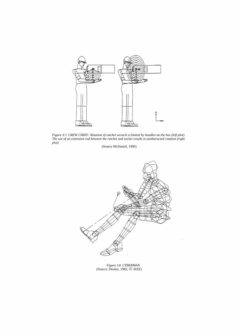
Figure 3.7. CREW CHIEF: Rotation of ratchet wrench is limited by handles on the box (left plot). The use of an extension rod between the ratchet and socket results in unobstructed rotation (right plot)
(Source McDaniel, 1990)
Figure 3.8. CYBERMAN (Source: Dooley, 1982, © IEEE)
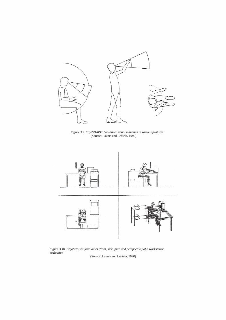
Figure 3.9. ErgoSHAPE: two-dimensional manikins in various postures (Source: Launis and Lehtela, 1990)
Figure 3.10. ErgoSPACE: four views (front, side, plan and perspective) of a workstation evaluation
(Source: Launis and Lehtela, 1990)
required. The system also permits the evaluation of postural stress resulting from vertical loads and provides recommendation charts giving guidance in various design areas. Further details can be found in Launis and Lehtela (1990).
ErgoSPACE (see Figure 3.10) is a three-dimensional man model with its own workplace modeling facilities. The system was developed to comply with the restrictions of microcomputers and therefore the graphic presentations of the man model and the workplace are greatly simplified. The man model has 17 joints and, in order to attain a reasonable response time, a stick model (i.e. the man model's link structure) representation is used for moving the model. The model can subsequently be enfleshed using an ellipsoidal wire frame. The anthropometric database for ErgoSPACE is identical to that for ErgoSHAPE. Users of the ErgoSPACE system have found it to be of rather limited use in designing workplaces because of its over reduced unnatural and confusing visual appearance. For further details see Launis and Lehtela (1990).
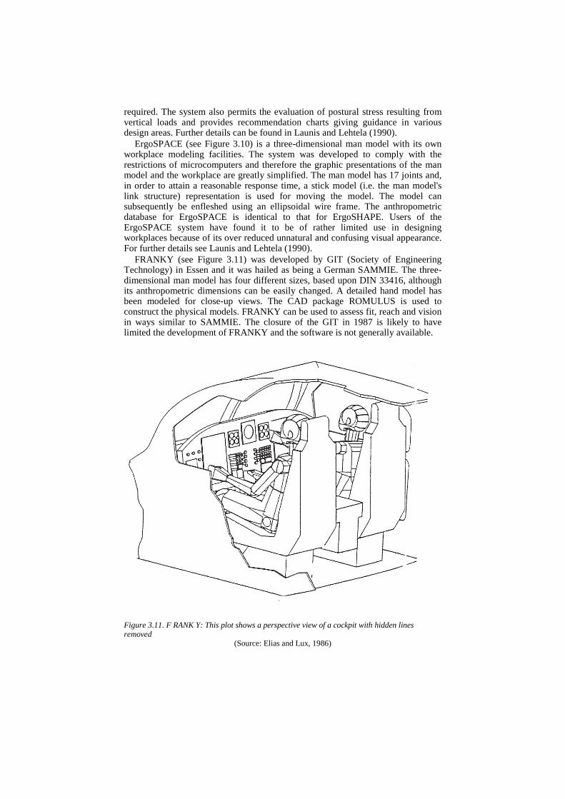
FRANKY (see Figure 3.11) was developed by GIT (Society of Engineering Technology) in Essen and it was hailed as being a German SAMMIE. The three-dimensional man model has four different sizes, based upon DIN 33416, although its anthropometric dimensions can be easily changed. A detailed hand model has been modeled for close-up views. The CAD package ROMULUS is used to construct the physical models. FRANKY can be used to assess fit, reach and vision in ways similar to SAMMIE. The closure of the GIT in 1987 is likely to have limited the development of FRANKY and the software is not generally available. Figure 3.11. F RANK Y: This plot shows a perspective view of a cockpit with hidden lines removed
(Source: Elias and Lux, 1986)

Figure 3.12. M1NTAC. This plot shows the operator lubricating grease nipples of a tractor's grabbing mechanism
(Source: Kuusisto and Mattila, 1990)
Further details can be found in Elias and Lux (1986). MINTAC (see Figure 3.12) stands for Man Machine INTerACtion and was
developed in 1984-5 by the Kuopio Regional Institute of Occupational Health and the University of Oulu. MINTAC was developed for the Computervision CAD/CAM system. The three-dimensional man model is based upon the anthropometric database published by Dreyfuss (1967) for the American civilian population, although the model is adjusted to simulate the wearing of winter clothes in order to evaluate difficult working postures encountered in Finnish agriculture and forestry. The simple man model contains six links: lower links (one rigid block which can be selected from a choice of 13 postures), back, upper arms and forearms. The man model was designed to be compatible with the OWAS working posture analysis system (Karhu et aI., 1977) although it is considered that MINTAC is not appropriate for widespread use because of its simplified posture and suitability only for the analysis of heavy work. Further details of this system and some other Finnish systems are given in Kuusisto and Mattila (1990).
SAMMIE (see Figure 3.13) stands for System for Aiding Man-Machine Interaction Evaluation. This system has been developed at Nottingham University and subsequently at Loughborough University. SAMMIE has been used extensively as a consultancy tool by its developers since the mid 1970s and SAMMIE CAD Ltd are now marketing their latest software worldwide as well as offering their ergonomics design services. This system is described in considerable detail later in this chapter but, briefly, it is an extremely versatile three-dimensional system comprising a man model of completely variable anthropometry, with comfort and maximum angles for each of its 17 joints, together with a functional workplace modeler. The system runs on engineering workstations such as SUN, APOLLO and Silicon Graphics and contains a suite of sophisticated ergonomics and work place modeling facilities. Recent descriptions of the SAMMIE system
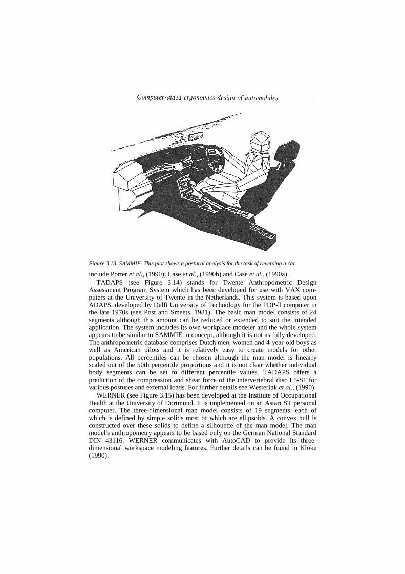
Figure 3.13. SAMMIE. This plot shows a postural analysis for the task of reversing a car
include Porter et al., (1990); Case et al., (1990b) and Case et al., (1990a). TADAPS (see Figure 3.14) stands for Twente Anthropometric Design
Assessment Program System which has been developed for use with VAX com-puters at the University of Twente in the Netherlands. This system is based upon ADAPS, developed by Delft University of Technology for the PDP-ll computer in the late 1970s (see Post and Smeets, 1981). The basic man model consists of 24 segments although this amount can be reduced or extended to suit the intended application. The system includes its own workplace modeler and the whole system appears to be similar to SAMMIE in concept, although it is not as fully developed. The anthropometric database comprises Dutch men, women and 4-year-old boys as well as American pilots and it is relatively easy to create models for other populations. All percentiles can be chosen although the man model is linearly scaled out of the 50th percentile proportions and it is not clear whether individual body segments can be set to different percentile values. TADAPS offers a prediction of the compression and shear force of the intervertebral disc L5-S1 for various postures and external loads. For further details see Westerink et al., (1990).
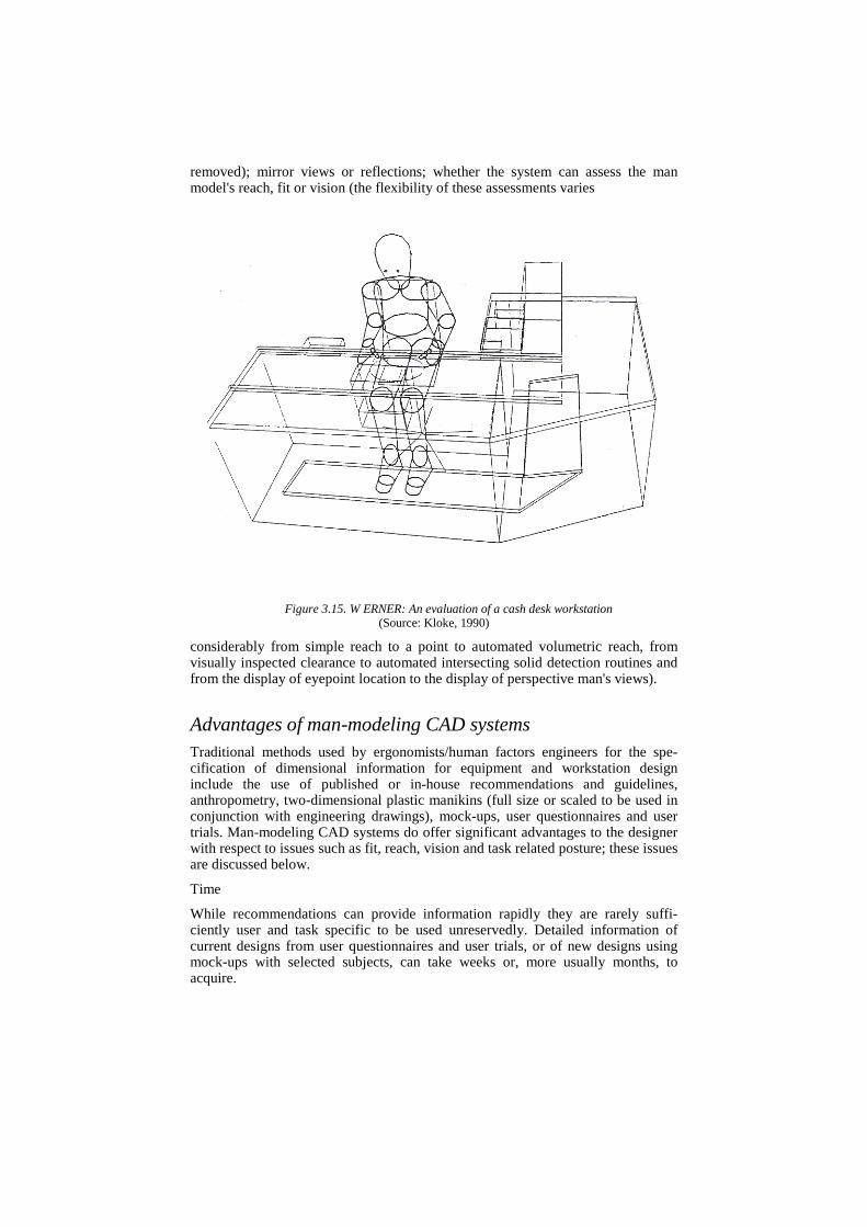
WERNER (see Figure 3.15) has been developed at the Institute of Occupational Health at the University of Dortmund. It is implemented on an Astari ST personal computer. The three-dimensional man model consists of 19 segments, each of which is defined by simple solids most of which are ellipsoids. A convex hull is constructed over these solids to define a silhouette of the man model. The man model's anthropometry appears to be based only on the German National Standard DIN 43116. WERNER communicates with AutoCAD to provide its three-dimensional workspace modeling features. Further details can be found in Kloke (1990).
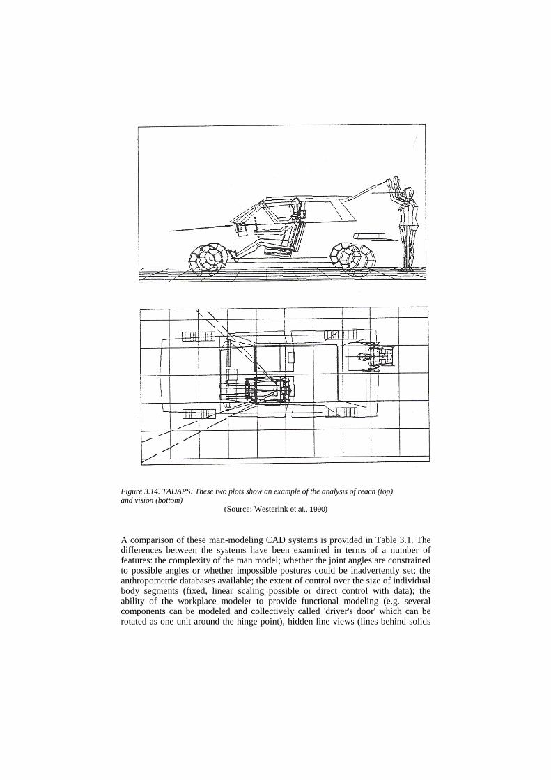
Figure 3.14. TADAPS: These two plots show an example of the analysis of reach (top) and vision (bottom)
(Source: Westerink et aI., 1990)
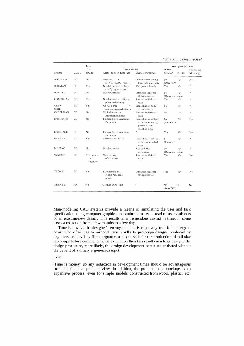
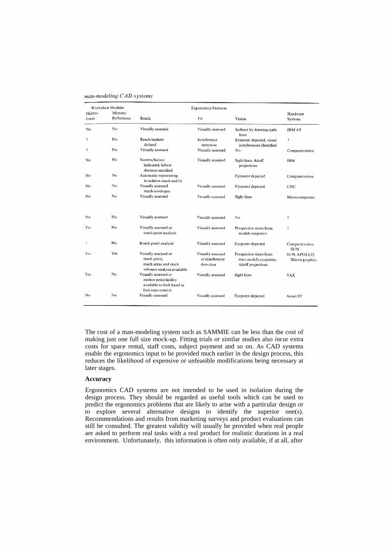
A comparison of these man-modeling CAD systems is provided in Table 3.1. The differences between the systems have been examined in terms of a number of features: the complexity of the man model; whether the joint angles are constrained to possible angles or whether impossible postures could be inadvertently set; the anthropometric databases available; the extent of control over the size of individual body segments (fixed, linear scaling possible or direct control with data); the ability of the workplace modeler to provide functional modeling (e.g. several components can be modeled and collectively called 'driver's door' which can be rotated as one unit around the hinge point), hidden line views (lines behind solids
removed); mirror views or reflections; whether the system can assess the man model's reach, fit or vision (the flexibility of these assessments varies
Figure 3.15. W ERNER: An evaluation of a cash desk workstation (Source: Kloke, 1990)
considerably from simple reach to a point to automated volumetric reach, from visually inspected clearance to automated intersecting solid detection routines and from the display of eyepoint location to the display of perspective man's views).
Advantages of man-modeling CAD systems Traditional methods used by ergonomists/human factors engineers for the spe-cification of dimensional information for equipment and workstation design include the use of published or in-house recommendations and guidelines, anthropometry, two-dimensional plastic manikins (full size or scaled to be used in conjunction with engineering drawings), mock-ups, user questionnaires and user trials. Man-modeling CAD systems do offer significant advantages to the designer with respect to issues such as fit, reach, vision and task related posture; these issues are discussed below.
Time
While recommendations can provide information rapidly they are rarely suffi-ciently user and task specific to be used unreservedly. Detailed information of current designs from user questionnaires and user trials, or of new designs using mock-ups with selected subjects, can take weeks or, more usually months, to acquire.
Man-modeling CAD systems provide a means of simulating the user and task specification using computer graphics and anthropometry instead of users/subjects of an existing/new design. This results in a tremendous saving in time, in some cases a reduction from a few months to a few days.
Time is always the designer's enemy but this is especially true for the ergon-omist who often has to respond very rapidly to prototype designs produced by engineers and stylists. If the ergonomist has to wait for the production of full size mock-ups before commencing the evaluation then this results in a long delay to the design process or, more likely, the design development continues unabated without the benefit of a timely ergonomics input.
Cost
'Time is money', so any reduction in development times should be advantageous from the financial point of view. In addition, the production of mockups is an expensive process, even for simple models constructed from wood, plastic, etc.
The cost of a man-modeling system such as SAMMIE can be less than the cost of making just one full size mock-up. Fitting trials or similar studies also incur extra costs for space rental, staff costs, subject payment and so on. As CAD systems enable the ergonomics input to be provided much earlier in the design process, this reduces the likelihood of expensive or unfeasible modifications being necessary at later stages.
Accuracy
Ergonomics CAD systems are not intended to be used in isolation during the design process. They should be regarded as useful tools which can be used to predict the ergonomics problems that are likely to arise with a particular design or to explore several alternative designs to identify the superior one(s). Recommendations and results from marketing surveys and product evaluations can still be consulted. The greatest validity will usually be provided when real people are asked to perform real tasks with a real product for realistic durations in a real environment. Unfortunately, this information is often only available, if at all, after
the production and sale of the product. The results of such an evaluation may highlight any postural problems, as a result of users' fit, reach and vision, as well as assessing comfort, convenience, behavior and performance measures. Ergonomics CAD systems can accurately predict problems of fit, reach and visions given that an appropriate anthropometric database and detailed task requirements are available for the prototype design. These predictions are mainly geometric in nature and result in the generation of the expected range or variety of working postures. The assessment of the consequences, in terms of comfort and/or performance, of these postures depends upon the CAD operator's knowledge base for its accuracy. Posture assessment is made considerably easier when research has identified optimum postures or a range of postures for specified tasks. For example, Rebiffe (1969) and Grandjean (1980) present comfort ranges for the various joint angles which should minimize the onset of pain or discomfort in the joints, ligaments and muscles while driving.
Man-modeling CAD systems have the potential to offer more accuracy than recommendations, guidelines and two-dimensional manikins because they can be made to simulate specific user groups and tasks and they can assess the postural consequences in three dimensions. While two-dimensional manikins are, even today, frequently used by many manufacturers it seems that only a few designers are fully aware of their limitations. One obvious problem is that most manikins only depict a side view of a person, resulting in only a two-dimensional evaluation of the design. This may explain why so many vehicle manufacturers design driving packages with the steering wheel and/or pedals offset from the seat or driver's centre-line, which is not only uncomfortable and a possible precursor of chronic health problems but it is also suspected of being a contributory cause of incidents of 'unintended acceleration' (Porter, 1989; see also Schmidt, this volume).
Two-dimensional manikins are often used without a knowledge of their origin in terms of user type (e.g. military/civilian data, age range, nationality, size, date of survey) and application (e.g. 'erect' or 'slumped' sitting height, percentile values for individual body segments). For example, we have found that several British vehicle manufacturers who market their vehicles in the United States were unaware that the sitting height (vertical distance from the compressed seat surface to the top of the head) of their 95th percentile adult male manikin was 50 mm shorter than the 95th percentile erect sitting height recorded by the National Health survey conducted in the United States some 30 years ago (Stoudt et aI., 1965). According to the results of this North American survey, the manikin actually had a 60th percentile erect sitting height. A further problem arises because the 95th percentile manikin is often used to define the height of the roof lining and the sunroof is subsequently designed to actually encroach around 25 mm into this already limited headroom. This results in an even larger percentage of the potential market being inadvertently 'designed out'.
Another major problem with two-dimensional manikins is that they can be used in a very simplistic way. For example, designers may have 50th and 95th percentile adult male mankins and a fifth percentile adult female manikin. The nature of these manikins gives support 10 the notion that people come either tall and long-limbed, short and short-limbed or somewhere in between. It has been repeatedly demonstrated that this is not true and that the inter-correlation between body dimensions is rather poor (e.g. Haslegrave, 1980). For example, Haslegrave (1986) reported that seated shoulder height varies from 30.6 to 39.5 per cent of stature which means that among men of average stature, their shoulder height may differ by as much as 122 mm. Furthermore, this torso proportion was found to have
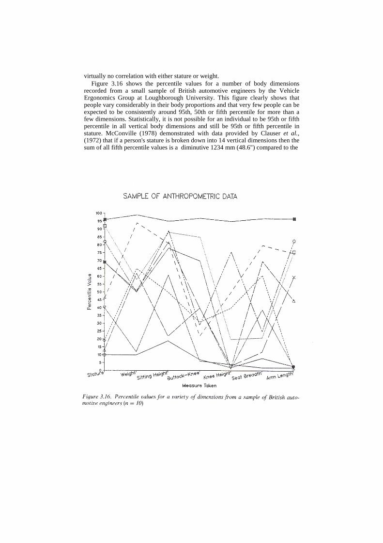
virtually no correlation with either stature or weight. Figure 3.16 shows the percentile values for a number of body dimensions
recorded from a small sample of British automotive engineers by the Vehicle Ergonomics Group at Loughborough University. This figure clearly shows that people vary considerably in their body proportions and that very few people can be expected to be consistently around 95th, 50th or fifth percentile for more than a few dimensions. Statistically, it is not possible for an individual to be 95th or fifth percentile in all vertical body dimensions and still be 95th or fifth percentile in stature. McConville (1978) demonstrated with data provided by Clauser et al., (1972) that if a person's stature is broken down into 14 vertical dimensions then the sum of all fifth percentile values is a diminutive 1234 mm (48.6") compared to the
fifth percentile stature of 1524 mm (60.0"). Conversely, the sum of all 14 dimensions set at 95th percentile values is a staggering 2022 mm (79.6") compared to the 95th percentile stature of 1722 mm (67.8"). The use of this approach would be very conservative indeed. Clearly this poses a disturbing problem for the manikin designer as no 'percentile man' can exist with the exception of the statistically acceptable, 50th percentile man' as 50th percentile values only are additive. However, the 'average man' concept has been known for a long time to be a fallacy. For example, Hertzberg (1960) describes the results of the study by Daniels and Churchill (1952) which showed that nobody in a sample of 4000 flying personnel was loosely' average' (i.e. man ± 15 per cent of the sample) in the 10 body dimensions examined.
The manikin designer can resort to other techniques to ensure that the manikins are statistically correct. One method is to measure a group of men or women who are fifth or 95th percentile in both stature and weight and to calculate the median values of all other dimensions among the group (Haslegrave, 1986). These median values are additive, allowing the manikin to remain statistically ‘correct'. One problem with this approach is that, unless the total sample is very large, the number of people who fall into the two extreme categories is likely to be quite small. For example, only five and 11 people were selected in Haslegrave (1986) to be fifth and 95th percentile, respectively, for both stature and weight. Such small groups may provide a distorted picture if any one individual was atypical to any significant extent. Another approach advocated by Robinette and McConville (1982) is based upon the use of regression equations to derive component dimensions for a person of a given percentile stature. These regression predicted values are additive and this method has the advantage that predictions from first to 99th percentile stature or weight can be easily calculated and that the method does not require a huge sample of subjects.
Whichever method is chosen to define a variety of statistically 'correct' manikins, there is still the problem of estimating the percentage of people accommodated by a particular design. A common mistake made by many automotive manufacturers is to use the fifth percentile female stature and 95th percentile male stature manikins to assess a driving package, assuming that if both of these manikins can be accommodated then so can 95 per cent of the adult population. This assumption is incorrect as it implies that those people 'designed out' because either their sitting height, hip breadth or leg length, for example, are greater than 95th percentile male values are all the same people. Similarly, all those with sitting eye height or leg length smaller than fifth percentile female values are assumed to be the same individuals. As these dimensions are not strongly correlated then these assumptions are incorrect. A study of air crew selection standards and design criteria analysis reported by Roebuck et al., (1975, p. 268) illustrates the problem perfectly as it was shown that nearly half of the air crew were ‘designed out' when the fifth to 95th percentile range was used on a large number of body dimensions (in this case 15 dimensions). Even limiting the number of dimensions to just seven (sitting height, eye height-sitting, shoulder height-sitting, elbow rest height, knee height, forearm-hand length and buttock-leg length) 'designed out' over 30 per cent of the available air crew.
This brief overview of the inherent problems with the use of manikins indicates the benefits that can arise from using three-dimensional man-modeling CAD systems with variable anthropometry. For example, the CAD operator has complete control of the dimensions or percentile values of the man model (assuming the system offers this facility) and can interactively change them in a matter of seconds. A variety of anthropometric data bases for different nationalities may be available, allowing the rapid creation of a large number of three-dimensional models. The operator can select to use models of known percentile values or use median or regression-predicted values for individual components. Additional man models can be constructed. For example, a model of 99th percentile male stature, with short arms and long legs for such a stature can be used to determine the rearmost position required of an adjustable steering wheel. Unfortunately data at this level of detail are not commonly presented in surveys; one of the exceptions being the anthropometric survey of Royal Air Force Aircrew by Simpson and Hartley (1981). The facilities provided by the computer man model encourage the designer to think more clearly about the use of anthropometric data in design.
One further option is potentially available to a computer man-modeling system and this is the assessment of the percentage of the target population that will be accommodated by a particular workstation design. This could be accomplished by two methods. First, the computer system could model all the individuals recorded in a relevant anthropometric survey and automatically position them in the workstation according to a range of predefined postures. Evaluations of fit, reach and vision could also be conducted automatically resulting in the identification of those individuals who failed to complete any of these tests successfully. The second approach would be to use the Monte Carlo method where appropriate survey data for individuals was not available. This method is briefly described in Churchill (1978) and would require the means, standard deviations and correlation coefficients for the various body dimensions.
The importance of ensuring that people can be comfortably accommodated and able to operate controls and view displays easily cannot be overstressed. The earlier example of cockpit design showed the alarming percentage of aircrew who would be 'designed out' if the crew stations were designed according to fifth to 95th percentile range for important body dimensions. While the accommodation criteria (e.g. sight lines for head-up displays, knee clearance when ejecting, control operation in high ‘g' environments) for pilots are considerably more demanding than for cars, car manufacturers often appear to overlook the fact that cars need to accommodate not just the drivers but whole families, including children and elderly relatives. Cars are often chosen to meet functional requirements such as this and many manufacturers may be unaware of the extent to which sales could be improved if fewer people were 'designed out'. A recent study by the Vehicle Ergonomics Group at Loughborough University (Porter et al., 1990) demonstrated the advantages of providing highly adjustable driving packages. This study interviewed 1000 randomly selected drivers at 3 motorway service stations and concluded that those drivers with highly adjustable driving packages reported less discomfort, even though they travelled greater distances and for longer periods of time, than those with more basic packages.
Communication
The quality of a design is greatly influenced by the extent to which the com-promises between the various constraints are successful. In order to achieve good compromises it is an important prerequisite that all the constraints have been identified at an early stage in the design. All too often the ergonomics issues have not been thoroughly researched early enough to enable optimum compromises to be made. Ergonomics is all about human variation and, as such, it is not always satisfied by existing legislation. Take, for example, EEC legislation concerning rearwards field of view in mirrors. This legislation requires that specified areas can be viewed from the legislative eye points which are two points vertically above the lowest, rearmost H-point (the H-point is the equivalent of a human's hip joint and it is measured using a standard SAE H-point manikin which has molded shapes to represent a person's back, buttocks and thighs which are weighted to simulate an average adult male. The seat is placed in the lowest and rearmost position). These legislative eyepoints take no consideration of the distribution of real driver's eyepoints as a function of seat adjustment and sitting eye height and also ignore the fact that the eyes move considerably when turning the head to look in the door mirrors. In addition, the legislative fields of view do not specify that areas adjacent to the vehicle should be visible in the mirrors (e.g. for buses, the area alongside the curb is of prime importance and must be visible to the driver to avoid potential accidents when leaving bus stops).
Communication is also of considerable importance to the ergonomist as it is to every member of the design team. The ergonomist can work most effectively when in collaboration with other members rather than acting as a critic assessing the efforts of others in producing the prototype. The collaboration is encouraged /by man-modeling CAD systems as the ergonomics input is brought forward to an earlier stage and the system can often act as a focal point for the design team before detailed engineering development work commences. Several design ideas can be rapidly assessed from an ergonomic viewpoint giving added flexibility to the design process.
Description of the SAMMIE system The SAMMIE system has benefited enormously from the detailed feedback provided by its extensive use as a consultancy and research tool, both by the system developers and others. The latest version of SAMMIE is highly interactive and the computing power now available in even the base model engineering workstations (e.g. SUN, APOLLO, Silicon Graphics) ensures a response time that could only have been dreamed of a few years ago.
It is perhaps worth pointing out that the version of SAMMIE currently distributed by SAMMIE CAD Ltd is markedly different from the system which was available through PRIME. Historically, both systems originated from Nottingham University. In 1978 the Research Council funding of SAMMIE ceased as it was deemed to have reached the stage where industry could support its further development. Consequently the software rights were passed to the British Technology Group for exploitation.
The software was modified by this group, the primary difference being the abolition of the menu interface. This system was marked by Compeda and
subsequently by PRIME. During this period the Nottingham team continued to develop their original version supported by the income generated from consultancy work. This work moved to Loughborough University in the early 1980s and in 1986 the originators set up SAMMIE CAD to develop and market their own system on a variety of computer hardware. As PRIME no longer support their version of SAMMIE, the details of SAMMIE presented in this chapter will refer to the current version developed by SAMMIE CAD only.
Workplace modeling
A boundary representation form of solid modeling (Requicha, 1970) is used to enable the system to be highly interactive whilst maintaining a sufficiently accurate three-dimensional model. It allows solid evaluations such as hidden line removal and interference checking without producing unduly complex models. Models are typically constructed from the variety of primitive shapes available such as cuboids, prisms, cylinders, spheres, meshes, polyprisms and solids of revolution. These primitives can be specified interactively by stating their unique name and dimensions (e.g. width, depth, height, radius etc. as required). Irregular solids can also be modeled. Although truly curved surfaces are not available, this has never been a cause for concern from an ergonomic point of view as sufficient accuracy can be obtained from a multi-faceted model. A reflection facility is available so that mirror image copies can be made so, for example, only one side of a car's exterior needs to be defined manually.
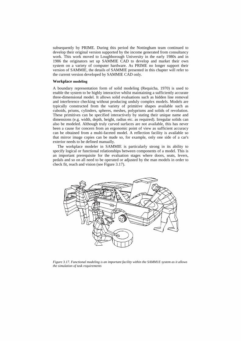
The workplace modeler in SAMMIE is particularly strong in its ability to specify logical or functional relationships between components of a model. This is an important prerequisite for the evaluation stages where doors, seats, levers, pedals and so on all need to be operated or adjusted by the man models in order to check fit, reach and vision (see Figure 3.17). Figure 3.17. Functional modeling is an important facility within the SAMM1E system as it allows the simulation of task requirements
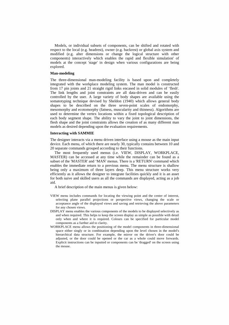
Models, or individual subsets of components, can be shifted and rotated with respect to the local (e.g. headrest), owner (e.g. backrest) or global axis system and modified (e.g. alter dimensions or change the logical structure with other components) interactively which enables the rapid and flexible simulation' of models at the concept 'stage' in design when various configurations are being explored.
Man-modeling
The three-dimensional man-modeling facility is based upon and completely integrated with the workplace modeling system. The man model is constructed from 17 pin joints and 21 straight rigid links encased in solid modules of ‘flesh'. The link lengths and joint constraints are all data-driven and can be easily controlled by the user. A large variety of body shapes are available using the somatotyping technique devised by Sheldon (1940) which allows general body shapes to be described on the three seven-point scales of endomorphy, mesomorphy and ecotomorphy (fatness, muscularity and thinness). Algorithms are used to determine the vertex locations within a fixed topological description of each body segment shape. The ability to vary the joint to joint dimensions, the flesh shape and the joint constraints allows the creation of as many different man models as desired depending upon the evaluation requirements.
Interacting with SAMMIE
The designer interacts via a menu driven interface using a mouse as the main input device. Each menu, of which there are nearly 30, typically contains between 10 and 20 separate commands grouped according to their functions.
The most frequently used menus (i.e. VIEW, DISPLAY, WORKPLACE, MASTER) can be accessed at any time while the remainder can be found as a subset of the 'MASTER' and ‘MAN' menus. There is a 'RETURN' command which enables the immediate return to a previous menu. The menu structure is shallow being only a maximum of three layers deep. This menu structure works very efficiently as it allows the designer to integrate facilities quickly and it is an asset for both naive and skilled users as all the commands are displayed, acting as a job aid.
A brief description of the main menus is given below:
VIEW menu includes commands for locating the viewing point and the center of interest, selecting plane parallel projections or perspective views, changing the scale or acceptance angle of the displayed views and saving and retrieving the above parameters for any chosen views.
DISPLAY menu enables the various components of the models to be displayed selectively as and when required. This helps to keep the screen display as simple as possible with detail only when and where it is required. Colours can be specified for particular model components as a further aid to clarity.
WORKPLACE menu allows the positioning of the model components in three-dimensional space either singly or in combination depending upon the level chosen in the model's hierarchical data structure. For example, the mirror on the driver's door could be adjusted, or the door could be opened or the car as a whole could move forwards. Explicit instructions can be inputted or components can be 'dragged' on the screen using the mouse.
MASTER menu is the main menu through which access is gained to the remainder of the other menus.
INPUT menu enables the interactive construction of model components using a query and response format. Data input from a disk file can also be accepted.
OUTPUT menu allows the output of various forms of file, model and plot data. GEOMETRY EDITOR menu enables the interactive modification of the geometry of model
components so that, for example, a display area can be made larger or smaller in any of its dimensions.
STRUCTURE EDITOR menu provides interactive control of the functional/logical relationships between model components. For example, this allows the man model to become a subset of a selected equipment model, such as the car seat, enabling both items to be moved in three-dimensional space as one unit when necessary.
HIDDEN LINES menu allows the creation of hidden line views, by deleting those lines behind solids, and the presentation of saved hidden line views.
MODIFICATIONS menu allows constraints to be placed on the position or orientation of model components so that seats, doors, pedals etc., can only operate in a realistic manner. This menu also enables the creation of simple functional commands such as 'LEFT DOOR OPEN' which can be used instead of the typical commands used in the WORKPLACE menu (i.e. LEFT DOOR LOCAL Z POSITIVE ROTATE 90).
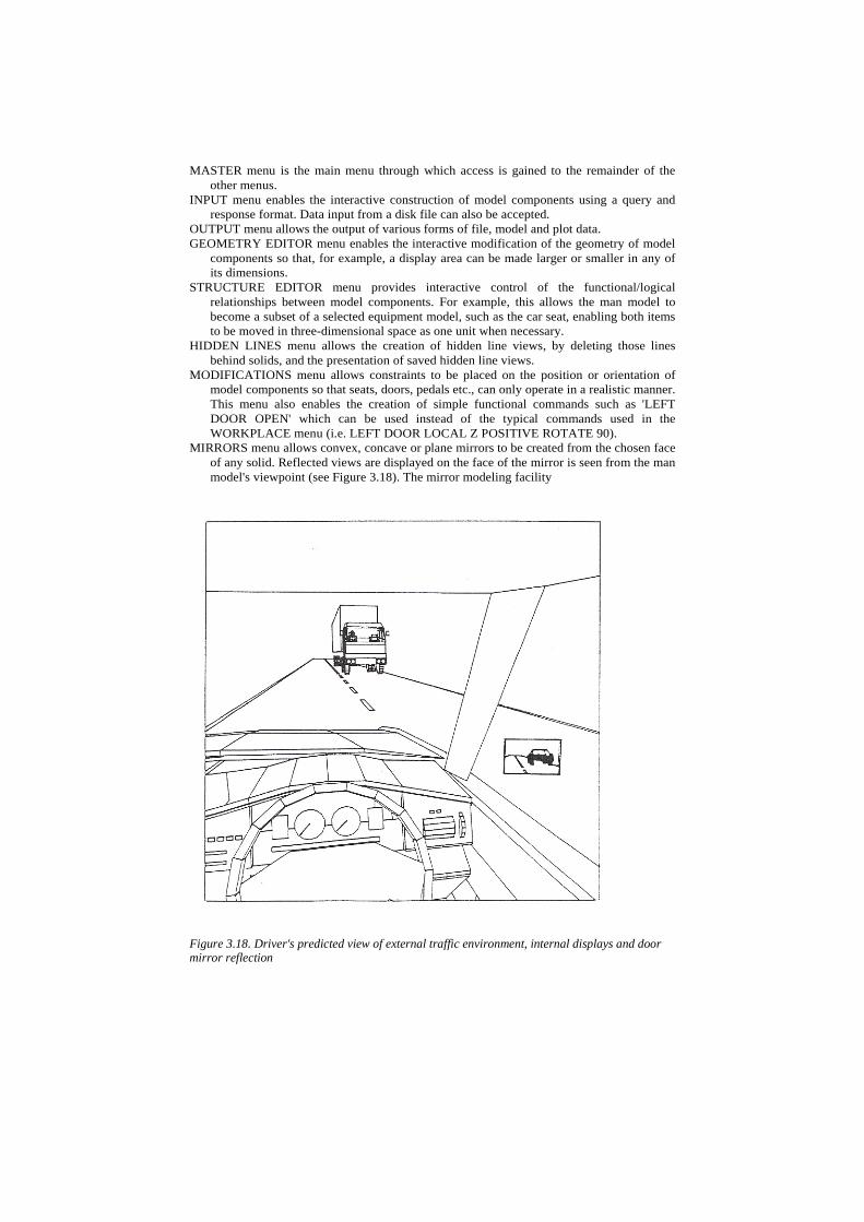
MIRRORS menu allows convex, concave or plane mirrors to be created from the chosen face of any solid. Reflected views are displayed on the face of the mirror is seen from the man model's viewpoint (see Figure 3.18). The mirror modeling facility
Figure 3.18. Driver's predicted view of external traffic environment, internal displays and door mirror reflection
MEASUREMENTS menu is a geometric measuring facility which enables minimum distances between any two solids to be calculated.
INTERFERENCE menu can be used to determine whether any chosen model components are intersecting. Any such solids are highlighted by flashing.
CONFIGURATION menu allows .the user to have control over the format of the screen display and the output of messages.
DATA STRUCTURE menu allows the user to interrogate and manipulate the data structure of the various models which have been created. Its primary purpose is for debugging.
MAN menu is the header menu for a suite of man-model related menus which are described below.
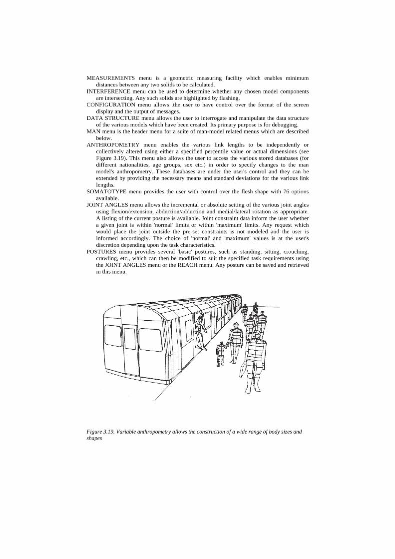
ANTHROPOMETRY menu enables the various link lengths to be independently or collectively altered using either a specified percentile value or actual dimensions (see Figure 3.19). This menu also allows the user to access the various stored databases (for different nationalities, age groups, sex etc.) in order to specify changes to the man model's anthropometry. These databases are under the user's control and they can be extended by providing the necessary means and standard deviations for the various link lengths.
SOMATOTYPE menu provides the user with control over the flesh shape with 76 options available.
JOINT ANGLES menu allows the incremental or absolute setting of the various joint angles using flexion/extension, abduction/adduction and medial/lateral rotation as appropriate. A listing of the current posture is available. Joint constraint data inform the user whether a given joint is within 'normal' limits or within 'maximum' limits. Any request which would place the joint outside the pre-set constraints is not modeled and the user is informed accordingly. The choice of 'normal' and 'maximum' values is at the user's discretion depending upon the task characteristics.
POSTURES menu provides several 'basic' postures, such as standing, sitting, crouching, crawling, etc., which can then be modified to suit the specified task requirements using the JOINT ANGLES menu or the REACH menu. Any posture can be saved and retrieved in this menu.
Figure 3.19. Variable anthropometry allows the construction of a wide range of body sizes and shapes
MAN'S VIEW menu provides perspective views from the man model's left, right or mean eye-point. The angle of view can be specified and the direction of view can be controlled by either asking the man model to look up/down or left/right with the eyes and/or head (both under joint constraints for normal and maximum angles) or by specifying the origin, vertex, edge or face of a model component that the user wishes to become the man model's center of interest (i.e. placed centrally on the screen only if the head and eye angles are within the joint constraints). Aitoff projections are an alternative method for assessing vision and this facility is available on the VIEW menu.
REACH menu provides a variety of automated methods to determine the reach capabilities of the man model for both feet and hands. In the reach point assessment the user can specify either the precise spatial location of the point to be reached, the object itself or an incremental movement from the current location of the hand or foot. A suitable algorithm selects the limb posture to be displayed by minimizing the extension of the joints away from their neutral positions and by preferring the greater extension of distal links to those that are more proximal. This algorithm does not necessarily predict the likely limb posture to be adopted by a human but it does confirm whether or not the reach attempt will be successful for a man model of given size and joint constraints. If the reach attempt fails, the relevant limb remains in its pre-test position and the user is informed of the failed attempt together with the distance by which it failed. An alternative approach is to produce reach contours which are overlaid on any surface of the chosen model component (in any orientation) as an aid to assessing suitable positions for controls. An extension of this approach is to produce reach volumes whereby reach is assessed over a number of imaginary surfaces parallel to either the frontal, sagital or transverse planes of the man model, or any other specified orientation, which is particularly useful in concept design. All reach evaluations only explore the range of joint angles in the limb itself. So, for example, hand reach evaluations involve the shoulder, elbow and wrist joints only. If appropriate to the task, the User can alter the man model's overall posture (e.g. bending forwards, twisting sideways) to extend the reach capabilities although the consequences of excessive bending and twisting upon musculoskeletal health, performance and fatigue must be considered carefully.
CHANGE OPERATOR menu allows the user to construct additional man models and to select the currently active model for evaluations of reach or vision.
Interfacing with other systems
SAMMIE has been written using standardized computer languages (Fortran 77 and C) and can be implemented on computer systems using Unix, the de facto standard operating system. Considerable development effort has been put into the implementation of computer graphics standards within SAMMIE. The various issues are discussed in detail in Case et al., (1991). Data exchange between CAD systems of similar function is fairly well established in two-dimensional systems using the Initial Graphics Exchange Specification (IGES; see Smith et al., 1988). However, standards are only just beginning to become effective for solid modeling systems such as SAMMIE. Typically, one might wish to use SAMMIE as a design originating concept tool, the results of which can then be passed on to other CAD/CAM systems for development or to plotting and visualization packages. It would also be useful if SAMMIE could receive geometric information from other three-dimensional CAD systems, evaluate it and return it to the originating system.
SAMMIE can create PHIGS archive file, Post Script and Computer Graphics Metafile (CGM, see Mumford and Liddell, 1988) output suitable for producing
hard copy on pen and laser plotters or passing geometric information to various systems such as business graphics, color enhancement, cartography and desktop publishing. SAMMIE currently can generate output files complying with IGES 4.0 which can be used to pass orthographic projections to a drafting package for dimensioning and annotation. The forthcoming IGES 5.0 should allow transfer of all the geometric aspects of a SAMMIE model to other systems although this would not include the non-geometric aspects such as the functionality of the workplace and man models.
A general methodology for using SAMMIE in automobile design SAMMIE has been used extensively in the design and evaluation of automobiles including cars, tractors, fork-lift trucks, buses, vans and heavy goods vehicles. Although each project had different aims, constraints and solutions, it is possible to describe the stages of a typical evaluation methodology.
Model the vehicle
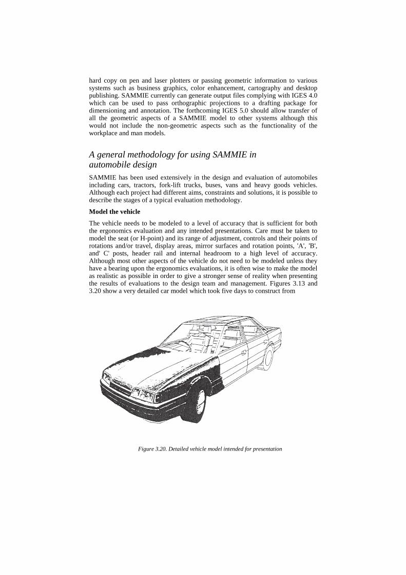
The vehicle needs to be modeled to a level of accuracy that is sufficient for both the ergonomics evaluation and any intended presentations. Care must be taken to model the seat (or H-point) and its range of adjustment, controls and their points of rotations and/or travel, display areas, mirror surfaces and rotation points, 'A', 'B', and' C' posts, header rail and internal headroom to a high level of accuracy. Although most other aspects of the vehicle do not need to be modeled unless they have a bearing upon the ergonomics evaluations, it is often wise to make the model as realistic as possible in order to give a stronger sense of reality when presenting the results of evaluations to the design team and management. Figures 3.13 and 3.20 show a very detailed car model which took five days to construct from
Figure 3.20. Detailed vehicle model intended for presentation
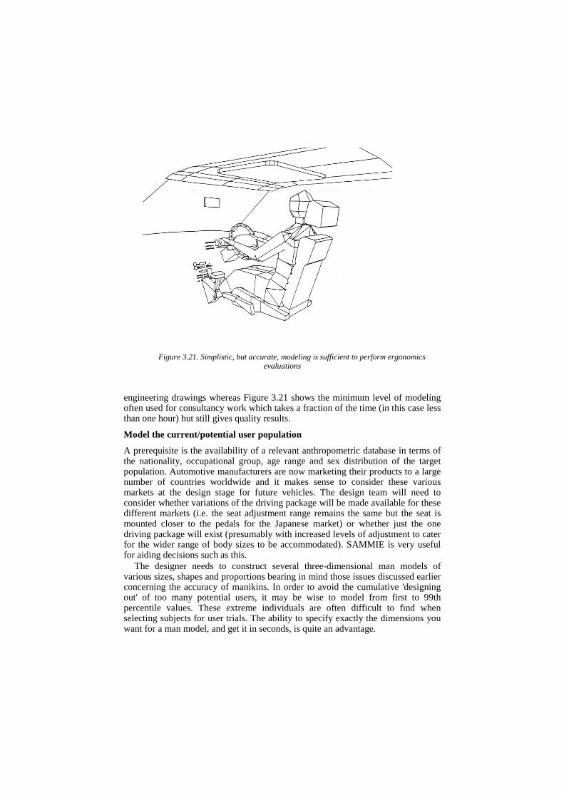
Figure 3.21. Simplistic, but accurate, modeling is sufficient to perform ergonomics evaluations
engineering drawings whereas Figure 3.21 shows the minimum level of modeling often used for consultancy work which takes a fraction of the time (in this case less than one hour) but still gives quality results.
Model the current/potential user population
A prerequisite is the availability of a relevant anthropometric database in terms of the nationality, occupational group, age range and sex distribution of the target population. Automotive manufacturers are now marketing their products to a large number of countries worldwide and it makes sense to consider these various markets at the design stage for future vehicles. The design team will need to consider whether variations of the driving package will be made available for these different markets (i.e. the seat adjustment range remains the same but the seat is mounted closer to the pedals for the Japanese market) or whether just the one driving package will exist (presumably with increased levels of adjustment to cater for the wider range of body sizes to be accommodated). SAMMIE is very useful for aiding decisions such as this.
The designer needs to construct several three-dimensional man models of various sizes, shapes and proportions bearing in mind those issues discussed earlier concerning the accuracy of manikins. In order to avoid the cumulative 'designing out' of too many potential users, it may be wise to model from first to 99th percentile values. These extreme individuals are often difficult to find when selecting subjects for user trials. The ability to specify exactly the dimensions you want for a man model, and get it in seconds, is quite an advantage.
Specify the task requirements
The task requirements should be specified for the driving task (e.g. reach and operate the controls, view the displays and view defined areas of the external environment either directly or by mirrors while maintaining a comfortable posture and meeting legislation where appropriate). In addition, other tasks should be considered such as ingress, egress, loading the trunk and maintenance operations (both for the user and the service mechanic). As SAMMIE is a general purpose system it can examine ergonomics issues in the manufacture of the automobile equally well, particularly where employees need to work in confined spaces or with robots.
Evaluate task efficiency and postural comfort
Depending upon the progress of the design, SAMMIE can either be used to specify control and display locations for future development or it can be used to evaluate a proposed or existing package. In the first case, the various man models are positioned with their joint angles within the recommended ranges for the particular vehicle type, based on published literature or in-house knowledge. Given that the pedals are likely to be fixed, the man models are positioned according to the accelerator heel point. Other constraints such as leg room for rear passengers, headroom for styling and whether the package will include an adjustable steering wheel will comprise the postures which can be adopted by the man models. If the vehicle is to be a luxury saloon then it would seem logical that postural considerations should outweigh other constraints although this is rarely the case with current vehicles. The ranges of joint angles can be used to minimize or maximize the control adjustability required. For example, male drivers with long legs and short arms can be expected to reach the steering wheel with fairly straight arms whereas female drivers with short legs and fairly long arms would have their elbows at an acute angle. This adaptability allows a large proportion of the user population to drive the vehicle with a fixed steering wheel. However, it should not be forgotten that optimum comfort levels and efficiency will only be realized if a fully adjustable steering wheel is provided enabling all drivers to have their preferred arm posture.
When SAMMIE is used to evaluate a proposed or existing package then the man models' postures are governed by the task requirements and the analysis focuses on which tasks are impossible (exceeds absolute joint constraints) or difficult (exceeds comfort range).
As stated earlier, SAMMIE does not evaluate task efficiency or comfort directly. The system provides postural data which can form the basis of usefully accurate predictions of efficiency and comfort by a user with the appropriate skills and/or knowledge base. We have used SAMMIE as a consultancy tool since the mid 1970s and our predictions and design proposals have been well-received by clients and end users.
Liaise within the design team
The early communication of problems identified by SAMMIE within the design team is essential to help ensure that optimum compromises can be made. In our consultancy experience it is extremely productive for those team members with
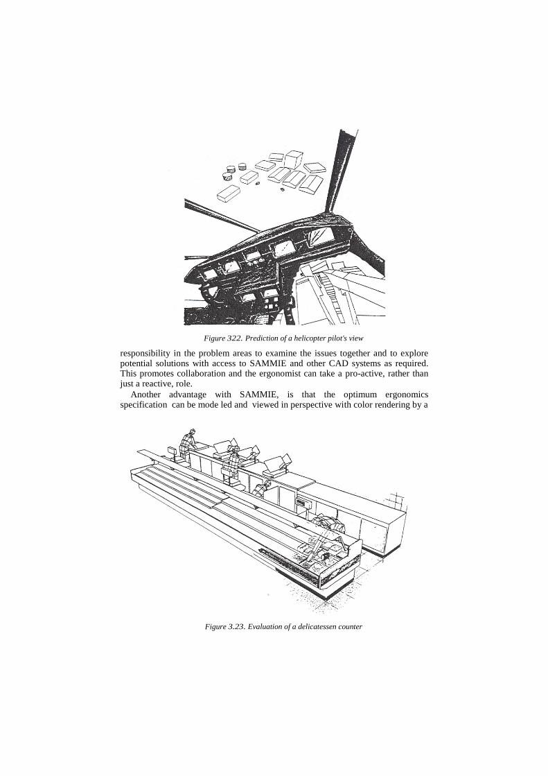
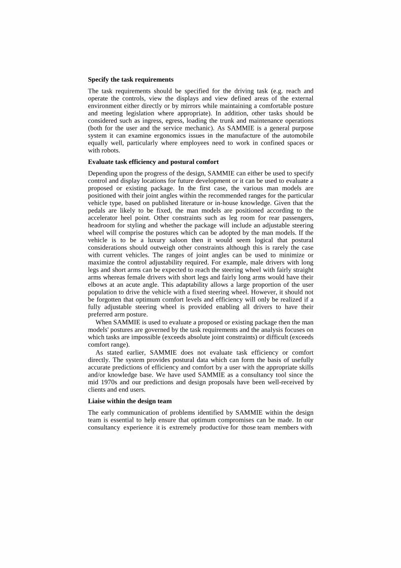
Figure 322. Prediction of a helicopter pilot's view
responsibility in the problem areas to examine the issues together and to explore potential solutions with access to SAMMIE and other CAD systems as required. This promotes collaboration and the ergonomist can take a pro-active, rather than just a reactive, role.
Another advantage with SAMMIE, is that the optimum ergonomics specification can be mode led and viewed in perspective with color rendering by a
Figure 3.23. Evaluation of a delicatessen counter
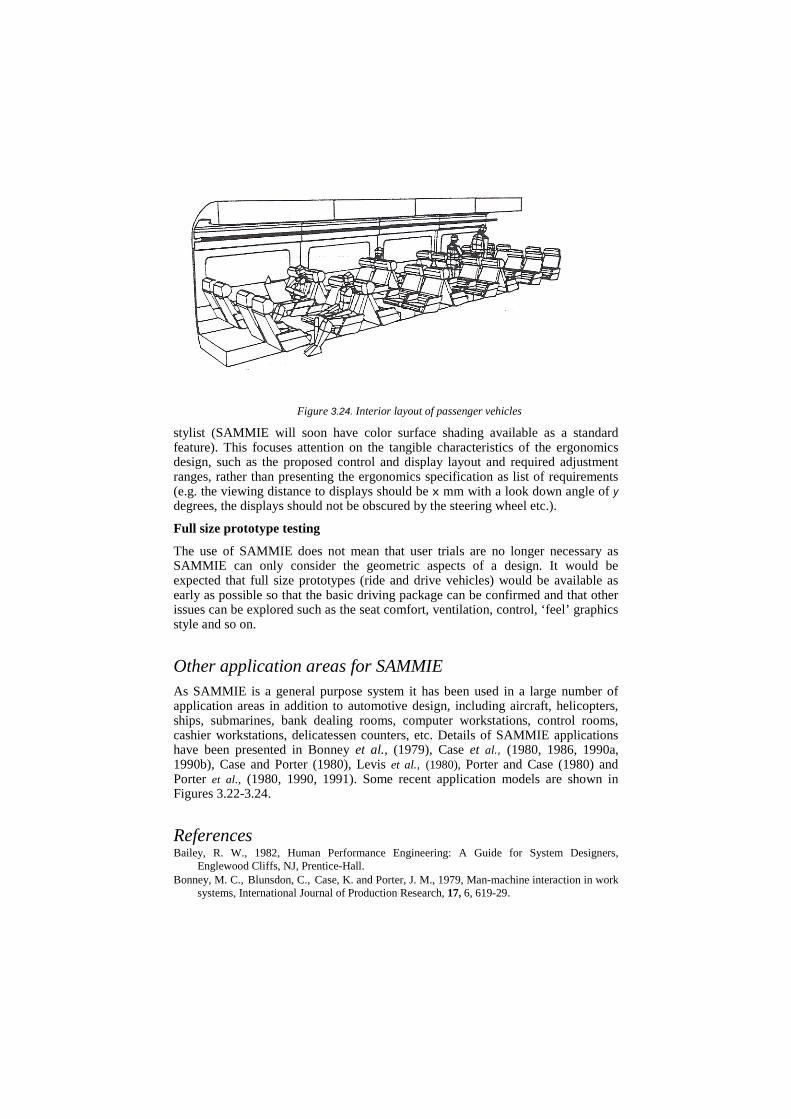
Figure 3.24. Interior layout of passenger vehicles
stylist (SAMMIE will soon have color surface shading available as a standard feature). This focuses attention on the tangible characteristics of the ergonomics design, such as the proposed control and display layout and required adjustment ranges, rather than presenting the ergonomics specification as list of requirements (e.g. the viewing distance to displays should be x mm with a look down angle of y degrees, the displays should not be obscured by the steering wheel etc.).
Full size prototype testing
The use of SAMMIE does not mean that user trials are no longer necessary as SAMMIE can only consider the geometric aspects of a design. It would be expected that full size prototypes (ride and drive vehicles) would be available as early as possible so that the basic driving package can be confirmed and that other issues can be explored such as the seat comfort, ventilation, control, ‘feel’ graphics style and so on.
Other application areas for SAMMIE As SAMMIE is a general purpose system it has been used in a large number of application areas in addition to automotive design, including aircraft, helicopters, ships, submarines, bank dealing rooms, computer workstations, control rooms, cashier workstations, delicatessen counters, etc. Details of SAMMIE applications have been presented in Bonney et al., (1979), Case et al., (1980, 1986, 1990a, 1990b), Case and Porter (1980), Levis et al., (1980), Porter and Case (1980) and Porter et al., (1980, 1990, 1991). Some recent application models are shown in Figures 3.22-3.24.
References Bailey, R. W., 1982, Human Performance Engineering: A Guide for System Designers,
Englewood Cliffs, NJ, Prentice-Hall. Bonney, M. C., Blunsdon, C., Case, K. and Porter, J. M., 1979, Man-machine interaction in work
systems, International Journal of Production Research, 17, 6, 619-29.
Brennan, L. and Fallan, E. F., 1990, The contribution of CAD to the enhancement of the ergonomist's role in the design process, in Karwowski, W., Genaidy, A. M. and Asfour, S. S. (Eds) Computer-Aided Ergonomics, pp. 501-11, London: Taylor & Francis.
Case, K., Bonney, M. C. and Porter, J. M. 1991, Computer graphics standards for man modeling, Computer Aided Design, 23, 4, 257-68.
Case, K., Bonney, M. C., Porter, J. M. and Freer, M. T., 1990a, Applications of the SAMMIE CAD System in Work place Design, in Haslegrave, C. M., Wilson, J. R., Corlett, E. N. and Manenica, I. (Eds) Work Design in Practice, pp. 119-27, London: Taylor & Francis.
Case, K. and Porter, J. M., 1980, SAMMIE-A Computer-Aided Ergonomics Design System, Engineering, 220, 21-25.
Case, K., Porter, J. M. and Bonney, M. C., 1986, SAMMIE: A Computer Aided Design Tool for Ergonomists, Proceedings of the Human Factors Society Annual Conference, Dayton, OH, pp. 694-8.
Case, K., Porter, J. M. and Bonney, M. C., 1990b, SAMMIE: A Man and Workplace Modelling System, in Karwowski, W., Genaidy, A. and Asfour, S. S. (Eds) Computer-Aided Ergonomics, pp. 31-56, London: Taylor & Francis.
Case, K., Porter, J. M., Bonney, M. C. and Levis, J. A., 1980, Design of Mirror Systems for Commercial Vehicles, Applied Ergonomics, 11,4,199-206.
Ciauser, C. E., Tucker, P. E., Reardon, J. A. and McConville, J. T., 1972, Anthropometry of Air Force Women, AMRL-TR-70-5, Aerospace Medical Research Laboratories, Wright-Patterson Air Force Base, OH.
Daniels, G. S. and Churchill, E., 1952, The 'Average Man'? T.N. WCRD 53-7, Wright Air Development Centre, Wright-Patterson Air Force Base, OH.
Dooley, M., 1982, Anthropomorphic modelling programmes-A survey, IEEE Computer Graphics and Applications, 2, 17-25.
Dreyfuss, H., 1967, The Measure of Man: Human Factors in Design, 2nd edn, New York: Whitney Library of Design.
Elias, H. J. and Lux, C., 1986, Gestatung ergonomisch optimierter Arbeitsplatze und Produkte mit Franky und CAD (The design of ergonomically optimized workstations and products using Franky and CAD), REFA Nachtrichten, 3, 5-12.
Grandjean, E., 1980, Sitting Posture of Car Drivers from the Point of View of Ergonomics, in Oborne, J. and Levis, J. A. (Eds) Human Factors in Transport Research, V 01. 2, pp. 205-13, London: Academic Press.
Groover, M. P. and Zimmers, E. W. Jr., 1984, CAD/CAM Computer-Aided Design and Manufacturing, Englewood Cliffs, NJ, Prentice-Hall.
Haslegrave, C. M., 1980, Anthropometric Profile of the British Car Driver, Ergonomics, 23, 436-67.
Haslegrave, C. M., 1986, Characterising the anthropometric extremes of the population, Ergonomics, 29(2),281-301.
Hertzberg, H. T. E., 1960, Dynamic anthropometry of working positions. Human Factors, 2, 147-55.
Karhu, 0., Kansi, P. and Kuorinka, 1., 1977, Correcting Working Postures in Industry: A Practical Method for Analysis, Applied Ergonomics, 8, 199-201.
Karwowski, W., Genaidy, A. M. and Asfour, S. S. (Eds), 1990, Computer-Aided Ergonomics, London: Taylor & Francis.
Kloke, W. B., 1990, WERNER: A personal computer implementation of an extensive anthropometric workplace design tool, in Karwowski, W., Genaidy, A. M. and Asfour, S. S. (Eds) Computer-Aided Ergonomics, pp. 57-67, London: Taylor & Francis.
Kuusisto, A. and Mattila, M., 1990, Anthropometric and biomechanical man models in computer-aided ergonomic design structure and experiences of some programs, in Karwowski, W., Genaidy, A. M. and Asfour, S. S. (Eds) Computer-Aided Ergonomics, pp. 104-14, London: Taylor & Francis.
Launis, M. and Lehtela, J., 1990, Man models in the ergonomic design of workplaces with the microcomputer, in Karwowski, W., Genaidy, A. M. and Asfour, S. S. (Eds) Computer-Aided Ergonomics, pp. 68-79, London: Taylor & Francis.
Levis, J. A., Smith, J., Porter, J. M. and Case, K., 1980, The impact of computer-aided design on pre-concept package design and evaluation, in Oborne, D. A. and Levis, J. A. (Eds) Human Factors in Transport Research, Vol. I, pp. 356-64, London: Academic Press.
Majchrzak, A., Chang, T-C., Barfield, W., Eberts, R. and Salvendy, G., 1987, Human Aspects of Computer-Aided Design, London: Taylor & Francis.
McConville, J. T., 1978, Anthropometry in Sizing and Design, in Anthropometric Source Book, Volume I: Anthropometry for Designers, NASA Reference Publication 1024, Washington, DC: Scientific and Technical Information Office.
McDaniel, J. W., 1990, Models for ergonomic analysis and design: COMBIMAN and CREW CHIEF, in Karwowski, W., Genaidy, A. M. and Asfour, S. S. (Eds) Computer-Aided Ergonomics, pp. 138-56, London: Taylor & Francis.
Meister, D., 1982, The role of human factors in system development, Applied Ergonomics, 13(2), 119-24.
Mumford, A. and Skall, M. (Eds), 1988, CGM in the Real World, Springer, Berlin. Pheasant, S., 1986, Bodyspace, London: Taylor & Francis.
Porter, J. M., 1989, Unintended acceleration and the design of foot pedals, Unpublished report, Vehicle Ergonomics Group, Department of Human Sciences, Loughborough University.
Porter, J. M., Almeida, G., Freer, M. and Case, K., 1991, The design of supermarket workstations to reduce the incidence of musculo-skeletal discomfort, in Queinnec et al. (Eds) Designing for Everyone and Everybody, London: Taylor & Francis.
Porter, J. M. and Case, K., 1980, SAMMIE--Can cut out the prototypes in ergonomic design, Control and Instrumentation, 12, 1,28-29.
Porter, J. M., Case, K. and Bonney, M. C., 1980, A Computer-Generated Three Dimensional Visibility Chart, in Oborne, E. J. and Levis, J. A. (Eds) Human Factors in Transport Research, Vol. 1, pp. 365-73, London: Academic Press.
Porter, J. M., Case, K. and Bonney, M. C., 1990, Computer Workspace Modelling, in Wilson, J. A. and Corlett, E. N. (Eds) Evaluation of Human Work: A Practical Ergonomics Methodology, pp. 472-99, London: Taylor & Francis.
Porter, J. M., Porter, C. S. and Lee, V. J. A., 1990, Car driver discomfort survey, Unpublished report, Vehicle Ergonomics Group, Department of Human Sciences, Loughborough University.
Post, F. H. and Smeets, J. W., 1981, ADAPS: Computer-aided anthropometrical design, Tijdschrift voor Ergonomic, 6 (4), 11-18 (in Dutch).
Rebilfe, R., 1969, Le Siege du conducteur: Son adaptation aux exigence fonctionneles et anthropometriques, in Grandjean, E. (Ed.) Sitting Posture, London: Taylor & Francis.
Requicha, A. A. G., 1970, Representations for rigid solids: theory, methods and systems, Computer Surveys, 12.
Robinette, K. M. and McConville, J. T., 1982, An alternative to percentile models, 810217, pp. 938-46, Warrendale, PA: Society of Automotive Engineers.
Roebuck, J. A., Kroemer, K. H. E. & Thomson, W. G. 1975, Engineering Anthropometry Methods, John Wiley & Sons.
Rothwell, P. L., 1985, Use of man-modelling CAD systems by the ergonomist, in Johnson, P. and Cook, S. (Eds) People and Computers: Designing the Interface, Cambridge University Press, pp. 199-208.
Sheldon, W. H., 1940, The varieties of human physique, New York: Harper & Bros. Simpson, R. E. and Hartley, E. V., 1981, Scatter diagrams based on the anthropometric survey of
2000 Royal Air Force aircrew (1970/71), Royal Aircraft Establishment Technical Report 81017, Farnborough, Hampshire.
Singleton, W. T., 1971, Systems Design, Applied Ergonomics, 2, 3.

Smith, B., Rinaudot, G. R. and Wright, T., 1988, Initial Graphics Exchange Specification (IGES) Version 4.0, US Department of Commerce.
Stoudt, H. W., Damon, A., McFarland, R. and Roberts, I., 1965, National Health Survey 1962: Weight, Height and Selected Body Dimensions of Adults, United States 1960-1962, Public Health Service Publication no. 1000 Series 11, no. 8, Washington, DC: US Government Printing Office.
Westerink, I., Tragter, H., Van Der Star, A. and Rookmaaker, D. P., 1990, TADAPS: A three-dimensional CAD man model, in Karwowski, W., Genaidy, A. M. and Asfour, S. S. (Eds) Computer-Aided Ergonomics, pp. 90-103, London: Taylor & Francis.