Computer Aided Engineering in Structural Design:
78
Olesia Klevanaia Computer Aided Engineering in Structural Design: trends and challanges in data processing Helsinki Metropolia University of Applied Sciences Civil Engineering Sustainable Building Engineering Bachelor's Thesis 30 May 2016
Transcript of Computer Aided Engineering in Structural Design:

Olesia Klevanaia
Computer Aided Engineering in Structural Design: trends and challanges in data processing
Helsinki Metropolia University of Applied Sciences
Civil Engineering
Sustainable Building Engineering
Bachelor's Thesis
30 May 2016
Abstract
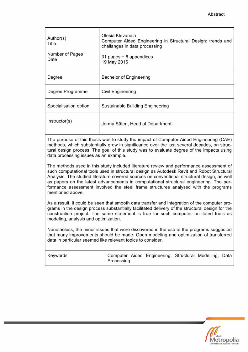
Author(s) Title Number of Pages Date
Olesia Klevanaia Computer Aided Engineering in Structural Design: trends and challanges in data processing 31 pages + 6 appendices 19 May 2016
Degree Bachelor of Engineering
Degree Programme Civil Engineering
Specialisation option Sustainable Building Engineering
Instructor(s) Jorma Säteri, Head of Department
The purpose of this thesis was to study the impact of Computer Aided Engineering (CAE) methods, which substantially grew in significance over the last several decades, on struc-tural design process. The goal of this study was to evaluate degree of the impacts using data processing issues as an example. The methods used in this study included literature review and performance assessment of such computational tools used in structural design as Autodesk Revit and Robot Structural Analysis. The studied literature covered sources on conventional structural design, as well as papers on the latest advancements in computational structural engineering. The per-formance assessment involved the steel frame structures analysed with the programs mentioned above. As a result, it could be seen that smooth data transfer and integration of the computer pro-grams in the design process substantially facilitated delivery of the structural design for the construction project. The same statement is true for such computer-facilitated tools as modeling, analysis and optimization. Nonetheless, the minor issues that were discovered in the use of the programs suggested that many improvements should be made. Open modeling and optimization of transferred data in particular seemed like relevant topics to consider.
Keywords Computer Aided Engineering, Structural Modelling, Data Processing

Contents
1 Introduction ............................................................................................................... 1
2 Traditional and Computer Aided Structural Design ................................................... 2
Traditional Structural Design .............................................................................. 2 2.1
Construction Engineering Process ............................................................... 3 2.1.1
Structural Engineering Process .................................................................... 4 2.1.2
Structural Design Method ............................................................................. 6 2.1.3
Computer Aided Structural Design ..................................................................... 8 2.2
Implementation of CAE in Construction Industry .......................................... 8 2.2.1
BIM-enabled Structural Engineering ........................................................... 10 2.2.2
Analysis and Optimisation in Structural Design .......................................... 12 2.2.3
3 Analysis of Steel Frames with Autodesk Revit and Robot ...................................... 14
General method of analysis .............................................................................. 14 3.1
Employed software applications ................................................................. 16 3.1.1
Computer procedure ................................................................................... 17 3.1.2
Case Study 1 .................................................................................................... 18 3.2
Case Study 2 .................................................................................................... 21 3.3
Test Results ...................................................................................................... 25 3.4
4 Discussion ............................................................................................................... 28
5 Conclusion .............................................................................................................. 31
6 References .............................................................................................................. 32
Appendices
Appendix 1. Case 1: Problem solution
Appendix 2. Case 1: Steel frame design and analysis in Autodesk Robot Structural
Analysis
Appendix 3. Case 1: Steel frame model integration between Revit and Robot
Appendix 4. Case 2: Problem solution
Appendix 5. Case 2: Steel frame design and analysis in Autodesk Robot Structural
Analysis

Appendix 6. Case 2: Steel frame model integration between Revit and Robot
1
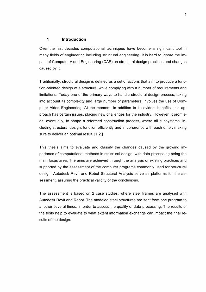
1 Introduction
Over the last decades computational techniques have become a significant tool in
many fields of engineering including structural engineering. It is hard to ignore the im-
pact of Computer Aided Engineering (CAE) on structural design practices and changes
caused by it.
Traditionally, structural design is defined as a set of actions that aim to produce a func-
tion-oriented design of a structure, while complying with a number of requirements and
limitations. Today one of the primary ways to handle structural design process, taking
into account its complexity and large number of parameters, involves the use of Com-
puter Aided Engineering. At the moment, in addition to its evident benefits, this ap-
proach has certain issues, placing new challenges for the industry. However, it promis-
es, eventually, to shape a reformed construction process, where all subsystems, in-
cluding structural design, function efficiently and in coherence with each other, making
sure to deliver an optimal result. [1,2.]
This thesis aims to evaluate and classify the changes caused by the growing im-
portance of computational methods in structural design, with data processing being the
main focus area. The aims are achieved through the analysis of existing practices and
supported by the assessment of the computer programs commonly used for structural
design. Autodesk Revit and Robot Structural Analysis serve as platforms for the as-
sessment, assuring the practical validity of the conclusions.
The assessment is based on 2 case studies, where steel frames are analysed with
Autodesk Revit and Robot. The modeled steel structures are sent from one program to
another several times, in order to assess the quality of data processing. The results of
the tests help to evaluate to what extent information exchange can impact the final re-
sults of the design.
2
2 Traditional and Computer Aided Structural Design
In order to describe and evaluate the applications of CAE in structural design in a com-
prehensible way, first, it is essential to analyze structural design itself. Taking a closer
look at the concept of structural design, its workflow and technical aspects allows the
formulation of fundamental questions that arise in course of any project. By doing so,
elaborate design process can be condensed to a finer model. Hence, the areas that
require the use of computational techniques become easier to detect. The next logical
step is to link these areas with available solutions offered by computer software. [3.]
As a final outcome, this chapter presents the most common computer aided (CA) struc-
tural engineering techniques together with development trends. The obtained infor-
mation is used as a frame of reference for performance tests of Autodesk Revit and
Robot Structural Analysis described in chapter 3.
Traditional Structural Design 2.1
This section describes structural design, which is carried out from three points of view:
as a stage in a construction design process, as an independent process and, finally, as
a mathematical problem. During the analysis of each of the three points of view possi-
ble technical issues become apparent. In short, the issues include communication and
data exchange difficulties between involved parties, as well as the delivery of a timely
and precise solution of the design problem. The solution of the design problem usually
means solving systems of simultaneous partial differential equations (PDE). [2,4.]
3
Construction Engineering Process 2.1.1
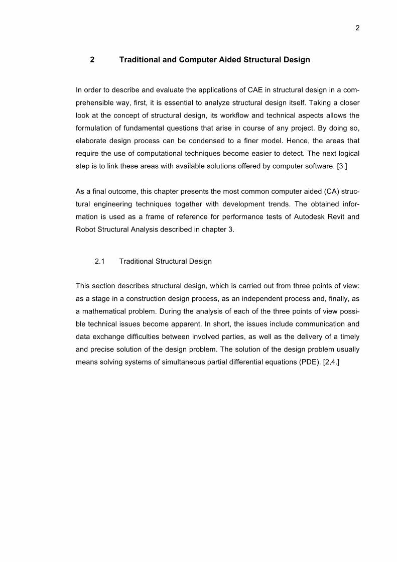
Construction engineering is a multidisciplinary area of expertise, which requires diverse
knowledge and skills. A workflow of a construction project is subject to certain variation,
yet there are a number of typical stages, as can be seen in figure 1. [5.]
Figure 1. Construction Engineering Process
Initially, a client develops a brief that states the main functions, which is then trans-
ferred to a design team for conceptual, or schematic, design. This stage utilizes simpli-
fied tools, in order to investigate a wide range of possibilities. The main goal here is to
outline the appearance of the building, major design solutions and methods for struc-
ture erection, along with specifications and restrictions. [1,5.]
As soon as the client approves the design, the team starts to work on a detailed build-
ing model which refines the existing design through editing and by encompassing new

4
details. Simultaneously, the manager can start procurement, which in turn strongly in-
fluences the design of the details. After the project information is complete, the actual
construction can commence. In order to assure sufficient quality, inspections by the
design team and authorities take place during this stage. [6,7,8.]
Despite the brevity of the description given above, it is clear that the number of parties
involved in a building project is fairly large. Therefore, apart from technical considera-
tions, which are discussed in section 2.1.1, timely and efficient communication is an-
other issue worth looking at. To a large extent interactions between the participants of
the project are carried out using computers. Therefore communication is strongly con-
nected with data exchange. Hence, efficient data processing and interoperability need
to be ensured during any design project. [2,5,7.]
Structural Engineering Process 2.1.2
By decomposing the process described above, structural design can be viewed as a
separate system. Schematic and detail design constitute the largest part of a structural
designer’s work, yet certain level of involvement is required during the whole construc-
tion project. As a matter of fact, structural design cannot be described as a continuous
uninterrupted process. To be more precise, the design team produces several solu-
tions, which are then edited and improved by maintaining a constant feedback loop
with the other involved parties including the architect, client, consultants etc. [5,9,10.]
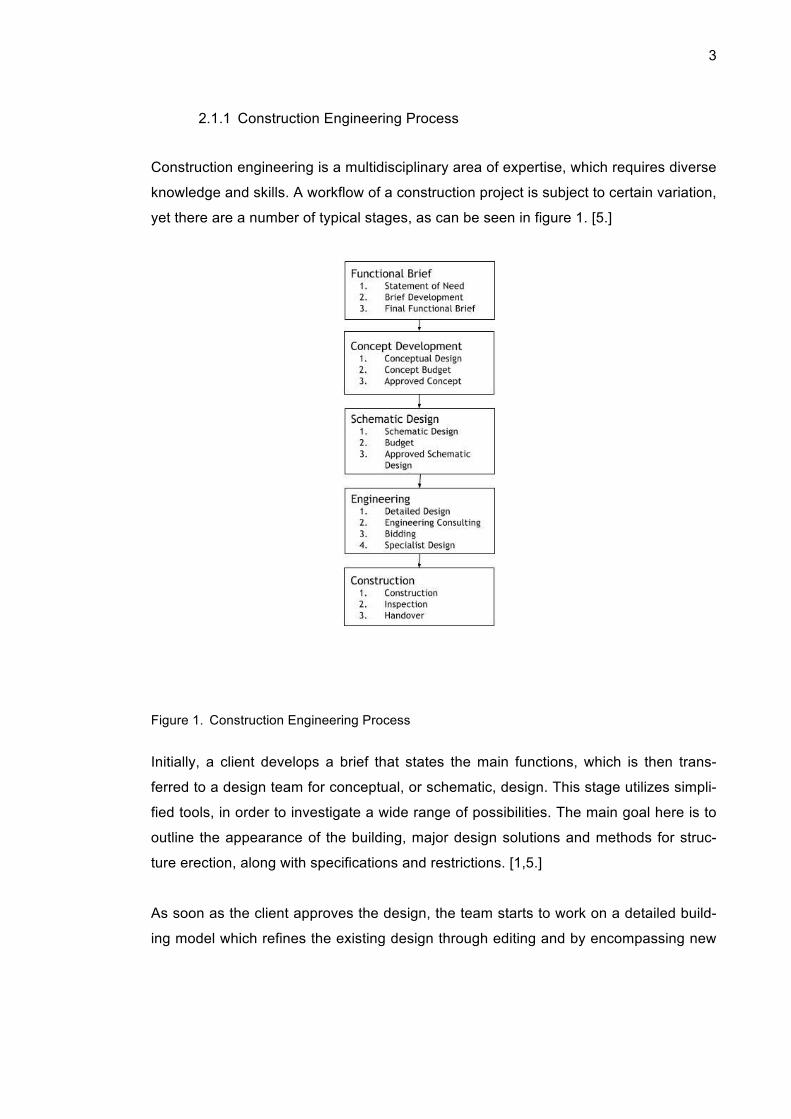
As can be seen in figure 2, the design process starts with functional design, where the
topology, shape and size of the structures are established. It also includes an estima-
tion of a sufficient area, the preliminary design of staircases and elevators, any atypical
structural requirements and building code limitations. [5,9.]
The next step is to select trial structure systems. Primary concerns here are material
selection, load resisting system and structural configuration. The trial systems are then
designed and analysed with some basic structural analysis methods meant for estima-
tion of approximate loads, member sizes and connections. [5,11.]
5
Based on the results of the preliminary analysis a system for detailed design is chosen.
This phase is typically carried out with computer programs and includes structural
modeling and load definition, followed by the computation of forces and deflections.
[12,13.]
Figure 2. Structural Design Process
The final detailed design is then evaluated against the criteria set during the initial func-
tional design. If the results are unsatisfactory, the project must be redesigned. Depend-
ing on the situation, the redesign could be either complete, which starts with a selection
of new trial systems and the repetition of all further steps, or partial, which consists of
reworking existing detailed designs. As soon as the desired optimum is achieved, the
drawings and specifications can be produced and the project moves to construction
phase. [10,14,15.]

6
Structural design is strongly interconnected with architectural design as well as with
procurement. Thus, it can be altered at any given stage of the construction process.
Apart from redesign during early stages, it is not uncommon for the architect or the
manager to request some changes to the finalized structural model during later stages
of the project. The reasons for this can be constructability problems, detection of colli-
sion and so on. These situations prove that flexibility is an essential characteristic of a
successful structural engineering process, yet in practice it is not always the case.
[2,4,16.]
Structural design process poses many technical challenges, which result in multiple
redesigns. This way the main goal of the structural design is to deliver satisfactory solu-
tion with as few redesigns, or iteration loops, as possible. In terms of CAE it means
implementation of more effective optimization techniques. [17.]
Structural Design Method 2.1.3
The final outcome of a structural design process is an arrangement of structural ele-
ments that optimally suits the set requirements. Most design problems are formulated
and solved with the analysis procedure. It is often necessary to carry out the analysis
repeatedly in the course of the design process. This approach allows the designer to
pinpoint better design solutions considering the budget and performance. [4,14.]
The intent of a structural analysis is to identify forces, stresses and displacements that
occur as a result of working loads. To assess the abovementioned reactions, it is cru-
cial to set up a model imitating the behaviour of the structure under assumed loads.
The main criterion for the adequate model is the relation between its accuracy and
simplicity. [4,17.]
From a theoretical point of view, parameters that influence structural responses are
well defined and can be solved with numerical methods. Its simplified procedure is
shown on figure 3. However, a growing complexity of designed systems, naturally,
leads to structural solutions becoming more complicated as well. As a result, in order to
find the problem solution more sophisticated computational procedures and higher lev-

7
el of expertise are required. Another essential steps are verification and interpretation
of numerical output. [14,18,19.]
Figure 3. Modelling process
An analytical model is created in order to calculate the displacements in the structure
and usually processed in a standard way. First, a structure is idealized to such level of
abstraction, where it can be solved. Typically, a real structure is reformulated into an
assembly of interconnected elements. Next, a model is generated, as local require-
ments for equilibrium are defined. Then the set of simultaneous equations which are
used for displacement calculation is formulated through requirements for interconnec-
tion of elements. Finally, the solution of simultaneous equations provides values of un-
known displacements, which are required for the final model. Then internal stresses
and forces are computed by solving local equilibrium requirements. [16, 20,21]
The quality of the analysis predominantly relies upon the computational techniques
utilized for the solution of the equilibrium equations. A higher precision can be achieved
by using better-defined models which approximate real structures to a very high extent.
[22,23.]

8
Computer Aided Structural Design 2.2
After outlining the issues that typically occur in the structural design, available corre-
sponding CA solutions are outlined. Even though the division suggested below is con-
ditional and implies substantial simplification, it can be accepted that each of the issues
is tackled with a certain computational tool or family of tools. The first group of prob-
lems is related to communication, including data exchange. They are supposed to be
eliminated by modeling tools. The second group of problems is caused by difficulties
with the mathematical formulation of the design problem. Such tools as computational
structural analysis and optimisation are expected to resolve these problems. [20,24.]
Implementation of CAE in Construction Industry 2.2.1
BIM and its implementation are typically expected to improve productivity and quality of
deliverables. However, there is still no uniform strategy for the incorporation of BIM
methodology in a construction process. Naturally, this fact causes some implementa-
tion issues. Yet despite possible complications at the early stages, information model-
ing brings certain benefits to the design procedure, including a lower number of inter-
disciplinary conflicts and a higher quality of the final output. [25,26,27.]
A universal definition of BIM is yet to be given. Nevertheless, it can be interpreted as a
multidimensional, historically evolving and complex concept. To begin with, it is a digital
representation of a building in 3D. It can also be perceived as the information library of
a project, as well as a communication and cooperation tool. The main trend is for BIM
to refine a construction project workflow and to strengthen the relationship between
design and construction. Along with all existing branches of building industry, structural
design is impacted by BIM and by the changes that it brings to the construction pro-
cess. [25,28.]
As stated above, the implementation of BIM could at times be challenging due to its
novelty. In spite of the lack of comprehensive research on the subject and limited ex-
perimental data, some modeling practices are more successful and some have proven
to be fruitless. For instance, for quite some time the concept of single software solution

9
for the whole construction process was dominant in the industry. However as it became
obvious that this paradigm is not feasible practically, distributed modeling started to
gain more attention and eventually proved to be a more successful approach. A com-
parison of these two approaches is summarized in Figure 4. [29,30.]
Hypothetically, integrated design offers multiple advantages. Still little progress has
been made to bring it to the industry. Currently there is no existing or developing appli-
cation that could store all the information for a construction project in a form that would
be understandable to all participants. Moreover, none is likely to appear at all. [20,30.]
Figure 4. Comparison of Integrated and Differentiated Approaches in Construction Industry
Development of a program with multiple environments for the different specialists is
rather complicated and would require an extremely high investment. Financial costs of
that size would turn the project unprofitable for the developer. Businesses would face
the need to disintegrate current operation practices and establish new ones, and users

10
would be exposed to a complicated interface, with a majority of functions that are never
used. Overall, financial, intellectual and social investments required for the success of
this paradigm along with the high risks undermine the possible benefits, making inte-
grated approach unattractive for the industry. [28,30.]
The distributed modeling paradigm, on the other hand, has shown more signs of suc-
cess. Such positive results can be attributed to the high flexibility of this approach. As
opposed to various experts working with the same software, distributed modeling pro-
motes highly specialized programs, where the created models are merged periodically,
in order to provide a platform for collaboration and comparison. [25,30.]
Changes caused by the introduction of such software in a company would be of a
moderate scale, keeping the existing practices intact. Additionally, there remains a
possibility to modify and experiment with available functions, crafting the most suitable
implementation pattern for a given company and allowing the company to develop in
the most organic way. Considering the wide range of businesses involved in construc-
tion, adaptability plays an important role. Lastly, a large number of vendors with a rela-
tively low market share should put the issue of interoperability forward. At the moment,
data processing with several software products within the same project considered to
be one of the most problematic areas. [30.]
BIM-enabled Structural Engineering 2.2.2
As it is now clear from section 2.2.1 which direction modeling in building industry is
headed to, impacts of computer modeling on the development of computer aided struc-
tural design in particular can be spotted as well. Some of the major trends of modeling
in structural design include an increase in data sharing, ever-growing iteration capabili-
ties of software products and the development of parametric design. [2,31.]
A constant exchange of information is an adjustment that affects all levels of a project.
These adjustments influence all specialists, including the structural designers, in a simi-
lar manner. First, increased transparency leads to a higher awareness of current situa-
tion, changing the approach to decision making. Different teams, such as structural,

11
electrical, HVAC and others who traditionally work separately and do not share almost
any facts regarding their progress, now get an opportunity to get familiar with the solu-
tions of the remaining specialists, thus making better-informed decisions in their own
domain. [32,33.]
Additionally, with growing information flows every piece of data is exposed to a larger
number of viewers within the same design team as well, which can be beneficial in a
number of ways. Importantly, the exposure of the design details to a larger number of
people can reduce errors and inconsistencies. If tracked at early stages, these issues
can be resolved with a minimal negative effect. Then, a higher level of exposure brings
a higher sense of responsibility, resulting in a better quality of the output. [31,32.]
The development of computational methods supports the advancement of modeling
software too, making it more efficient and productive. With a higher automation level
and a lower time required for a single operation, iterative capabilities of structural de-
sign programs increase significantly. Hence, the higher productivity means a larger
variety of possible options to be considered and evaluated, which leads to a more re-
fined solution. [34.]
Parametric modeling is another important development in CAE area. The ability to use
an object library, where the geometry of an object is related to its properties, could ad-
vance many procedures. For example, the use of object-oriented software can facilitate
design, as individual components can be queried for material and performance data, as
well as for cost. [28,35.]
The development of the parametric modeling is also supported by the fact that manu-
facturers create open libraries with models of their products. This way, a parametric
relationship between form and components of a building can be established right after
initial sizing and form organization, resulting in a better overall optimization of the struc-
ture. [27,20.]

12
Analysis and Optimisation in Structural Design 2.2.3
As mentioned above in section 2.2.2, advancements in operational speed and output
data quality of computational methods strongly encouraged, among many things, the
incorporation of computer-aided structural design techniques in construction engineer-
ing process. The most prominent tools used to increase the operational speed and data
quality include finite element analysis (FEA) along with multiple optimisation methods.
With the development of computational engineering, especially finite element method
calculations, processes of optimisation were integrated into design activities, in order to
save the time required for obtaining a satisfactory result. [29,36.]
The technical procedure of computational structural analysis is not in the scope of this
study, yet a basic interpretation of the issue could help to gain better understanding of
the subject. One of the ways to look at a structural analysis is by dividing it into three
major parts. [27,29.]
As can also be seen in figure 5, a model created by architects should be pre-
processed. In other words, the project needs to be reformulated using simple structural
elements, such as beams and columns. [37.]
Figure 5. Computational Structural Analysis Process
When the model is assembled, the analysis is carried out with computer programs. The
finite element method (FEM) is the most widely used form of analysis, as it provides
solutions to complex problems while maintaining a high level of automation. The finite
element method for structural analysis is based on substitution of a real continuous
13
structure with a model that consists of finite number of elements. These assumed ele-
ments possess known material properties, including elasticity and inertia, which are
expressed in a matrix form. Assembled according to the rules derived from elasticity
theory, matrices describe the responses of the actual structure. The major concept to
keep in mind, when discussing FEM, is that once the size of the defined elements be-
comes small enough, the model’s behaviour converges to that of the real structure and
it is possible to determine the deformations with sufficient accuracy. [29,30.]
After the analysis, engineers should interpret the results. Furthermore, they introduce
adjustments to an existing design. Even though structural analysis is predominantly
used to evaluate the quality of the suggested design, more appropriate structural solu-
tions can be offered. One of the ways to find more suitable solutions supposes the use
of certain patterns and search mechanisms. This process denotes the shift from analy-
sis to optimization. [37.]
Optimization in structural design deals with three aspects, the size, shape and topolo-
gy. Optimizing the shape and area is typically less complicated and allows for the con-
trol of such factors as fabrication costs and structural reliability. Topology, on the other
hand, can be more challenging to optimize. It deals with the connectivity of the ele-
ments, and when optimizing it, the design should be viewed from a more global per-
spective. Nonetheless, the latest studies indicate that the best possible results come
from the simultaneous optimization of all three aspects. [2,37.]
From a technical point of view, structural design can be said to significantly benefit from
implementation of computational tools which handle sophisticated calculations with a
higher accuracy in a shorter period of time, decreasing the overall cost. The develop-
ment of computer optimization tools and FEM serve as major examples for that.
14
3 Analysis of Steel Frames with Autodesk Revit and Robot
The practical part of this thesis aims to assess the level of data transfer quality offered
by Autodesk Revit and Robot. Problems, which are analysed with the method de-
scribed below, are used to demonstrate capabilities of the computer programs and to
draw conclusions regarding performance and possible future developments of the pro-
grams.
As it was stated in chapter 2, distributed design showed to be rather successful. How-
ever, the use of distributed deign approach in CAE development places certain chal-
lenges on the industry. For instance, any software is now supposed to accommodate
an ever-increasing number of model and data transfers in the course of a construction
project. Results of the tests carried out in this chapter give the basis for the evaluation
of the current situation in the computer-aided structural design. [9,10.]
The tests carried out in this final project clarify how compatible different computer pro-
grams are and how much their repetitive synchronization can affect the quality of a
structural model. Structural models used in the case studies are all steel hyperstatic
structures under a uniformly distributed load. The moment diagrams for the structures
need to be determined. In order to ensure the reliability of the results, the problems
were preliminary solved manually with Excel. There were two pieces of structural anal-
ysis software used in the practical part, Autodesk Revit and Robot, both of which are
developed by the same company and widely used in the industry. [38,39.]
As a final outcome, the test results are supposed to provide sufficient information for
software evaluation. Based on the case studies, the current synchronization procedure
is assessed and any possible drawbacks and development suggestions are outlined.
General method of analysis 3.1
The tests carried out in this study are based on several cases, the main goal of which
is to determine the quality of data transfer and, if possible, distinguish areas worth im-
proving. The general analysis procedure adopted for the tests is described in this sec-

15
tion and schematically shown in figure 6. Case-specific details are elaborated further in
corresponding sections.
Figure 6. General test procedure
In order to answer the questions posed in section 2 above, tests on different structures
are carried out. Every test procedure is performed in a similar manner and can be di-
vided into three steps: hypothesis construction, testing and analysis of results. [7,17.]
For each case, certain unknowns should be calculated with both Autodesk Revit and
Robot Structural Analysis. The outputs of each program are expected to be coherent
and, additionally, stay within the same order of magnitude as preliminary calculated
results. The results are obtained through manual calculations with Excel for repetitive
operations. As it can be understood, the availability of preliminary results and their ac-
curacy are significant for the overall assessment. For this reason, the test structures
are chosen with a view to obtaining unambiguous results which can be checked manu-
ally. [9.]
Once the hypothesis is formulated, tests are carried out, and their results are recorded
and stored. The main areas of focus here are the consistency of the calculation results
on one hand, and their accuracy after multiple conversions from one format to another,
on another hand. Derived results are then compared with each other, as well as with

16
the preliminary manual calculations. This provides sufficient background for the evalua-
tion of the used software products. [25.]
Employed software applications 3.1.1
The programs used for the study were Autodesk Revit and Robot Structural Analysis
Professional. Both programs are developed by Autodesk, which ensures a high level of
compatibility during the simulations. In addition to this, the fact that Autodesk is one of
the leaders in the industry means that both programs are widely used in construction
projects. [38,39.]
Figure 7. Interface of Autodesk Revit
Autodesk Revit, work environment of which is presented in figure 7, is a design and
construction program, which supports implementation of BIM at all stages of a con-
struction project. It promises, among other features, to provide precise models, facili-
tate optimisation processes and give a platform for effective communication. [39.]

17
Autodesk Robot Structural Analysis is a structural analysis program based on FEA. It
allows engineers to carry out design, simulation and analysis procedures, as well as
code checking for any type of structures. It also has a link to Autodesk Revit, assuring
sufficient interoperability. [38.]
Computer procedure 3.1.2
Based on sections 3.1 and 3.1.1 the test procedure is described. Its schematic repre-
sentation can be seen in figure 8.
Figure 8. Procedure of computer simulation
Initial modelling and analysis are performed with Autodesk Robot Structural Analysis
Professional. The created model is then transferred to Autodesk Revit, where it can be
modified if necessary. The updated model can then be delivered back to Autodesk Ro-
bot with all adjustments intact. The produced results are studied and summarized, in
order to assess the level of data processing.
18
Case Study 1 3.2
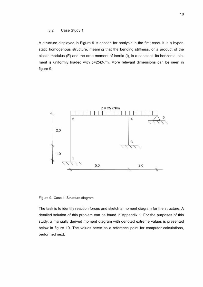
A structure displayed in Figure 9 is chosen for analysis in the first case. It is a hyper-
static homogenous structure, meaning that the bending stiffness, or a product of the
elastic modulus (E) and the area moment of inertia (I), is a constant. Its horizontal ele-
ment is uniformly loaded with p=25kN/m. More relevant dimensions can be seen in
figure 9.
Figure 9. Case 1: Structure diagram
The task is to identify reaction forces and sketch a moment diagram for the structure. A
detailed solution of this problem can be found in Appendix 1. For the purposes of this
study, a manually derived moment diagram with denoted extreme values is presented
below in figure 10. The values serve as a reference point for computer calculations,
performed next.
19
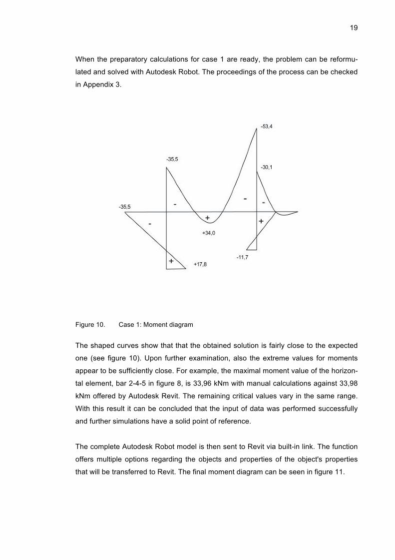
When the preparatory calculations for case 1 are ready, the problem can be reformu-
lated and solved with Autodesk Robot. The proceedings of the process can be checked
in Appendix 3.
Figure 10. Case 1: Moment diagram
The shaped curves show that that the obtained solution is fairly close to the expected
one (see figure 10). Upon further examination, also the extreme values for moments
appear to be sufficiently close. For example, the maximal moment value of the horizon-
tal element, bar 2-4-5 in figure 8, is 33,96 kNm with manual calculations against 33,98
kNm offered by Autodesk Revit. The remaining critical values vary in the same range.
With this result it can be concluded that the input of data was performed successfully
and further simulations have a solid point of reference.
The complete Autodesk Robot model is then sent to Revit via built-in link. The function
offers multiple options regarding the objects and properties of the object's properties
that will be transferred to Revit. The final moment diagram can be seen in figure 11.

20
Further, once the program processes the model, the examined structure can be viewed
in Revit. The properties of the model, including the materials, dimensions and topology,
remain unchanged, as well as the assumed loads, keeping the moment diagram identi-
cal to the one in Robot.
Figure 11. Case 1: Moment diagram generated with Autodesk Robot
Revit also allows the designer to modify the loads. In Case 1, uniform 25 kN/m load
was reduced to 15 kN/m. The updated model is then sent to Robot via the built-in link
for a new analysis. When the model is viewed in Robot the loads are reduced from 25
kN/m to 15 kN/m, proving compatibility of the programs. Finally, after the analysis it can
be stated that the latest model of the structure, which is displayed in figure 12, is no
longer stable.

21
Figure 12. Updated Robot model
As a result, it is possible to say that the data transfer between Revit and Robot in this
case study was quite successful and smooth. Both programs retained the essential
information and the results of the analysis stayed coherent with the expected values.
Case Study 2 3.3
The second case to be analysed is the structure shown in figure 13. It is a hyperstatic
homogenous structure, meaning that the bending stiffness, or a product of the elastic
modulus (E) and the area moment of inertia (I), is a constant. Its horizontal element is
uniformly loaded with p=42kN/m. More relevant dimensions can be seen in the figure
13.
Similarly to the 1st case, the task is to identify the reaction forces and sketch a moment
diagram for the structure. Appendix 2 offers a full solution to the problem. A moment
diagram with denoted extreme values, drawn from the calculations in Appendix 2. Fur-

22
ther computations with Autodesk Robot and Revit are compared to these results for the
reference.
Figure 13. Case 2: Structure diagram
When the preparatory calculations for the Case 2 and the moment diagram are ready,
the problem can be reformulated and solved with Autodesk Robot. The proceedings of
the process can be checked in Appendix 4.
It can be seen from the similarly shaped curves that the obtained solution is fairly close
to the expected one (figure 14). Upon further examination the extreme values for mo-
ments appear to be sufficiently close also. For example, the manually calculated mo-
ment value at the fixed support, point A on Figure 11 is -317,65 kNm against -317,77
kNm offered by Autodesk Revit. The remaining critical values vary in the same range.
Consequently, it can be concluded that the input of data was performed successfully
and further simulations have a solid point of reference.

23
The complete Autodesk Robot model is then sent to Revit using the built-in link. The
link allows the engineer to specify which objects and properties should be transferred.
Figure 14. Case 2: Moment diagram
Further, once processed by the software, the examined structure can be viewed in
Revit. The properties, including materials, dimensions and topology of the structure
remain unchanged, as do the assumed loads, keeping the moment diagram identical to
the one in Robot.
In this case two changes to the initial model were made: one element was changed
and the magnitude of load was increased. First, The changes were begun with modify-
ing properties of the lower horizontal bar, element B-D in figure 13. Its section was
changed from HE100 to HE320, while the remaining elements were not changed. Then
the load introduced to the structure was increased from 42 kN/m to 100 kN/m. [38.]

24
Figure 15. Case 1: moment diagram generated with Autodesk Robot
The updated model is then sent back to Robot, figure 15, and analysed. In figure 16 it
can be seen that the modified bar is also updated in Autodesk Robot. The section
properties and loads are updated as well. Lastly, an analysis on the structure is per-
formed for the second time. The analysis states that the frame is no longer stable due
to the introduced changes.

25
Figure 16. Case 2: updated Robot model
The tests showed that the data transfer between Revit and Robot was quite successful
and smooth in this case. Both programs retained the essential information and the re-
sults of the analyses stayed coherent with the expected values.
Test Results 3.4
After considering the output produced during the tests, models designed in Autodesk
Robot can be transferred to Revit and back with minor to none distortion. However that
is true in the cases with conventional structures and loads within typically expected
range. Load cases described by Eurocode can be used as an example. [38,39]
Moreover, changes introduced in Revit are also displayed in Autodesk Robot after syn-
chronisation. Nonetheless, in order to avoid inconsistencies in the calculation the soft-
ware-specific rules for definition of geometrical surfaces and loads should be followed
accurately. Average construction projects can use Autodesk Robot and Revit and ex-
pect the high level of synchronization and data exchange. Aside from that, the tests
show that distributed design becomes more common and is recognized by larger soft-

26
ware developers, such as Autodesk, who also provide a link that ensures smooth in-
formation exchange between users of different products. Still data exchange properties
of any program are strongly dependant on parameters determined by the developer
and can at times serve as limitations. [35,38,39.]
Talking about special requirements during a design process in Autodesk Robot and
Revit, it is essential to pay close attention to two instances. Firstly, a clear and con-
sistent definition of the coordinate system and sign convention plays a significant role
in achieving accurate results. Furthermore, units and their scale should be double-
checked as well for the same reason.
Secondly, during the synchronization of Revit and Autodesk Robot, the definition of
loads needs to be traced carefully, as their listing in Revit is slightly different from that
in Autodesk Robot. Input values do not get altered after the integration of the model,
though the load groups might be automatically re-named in Robot to match the groups
in Revit, as the latter is typically serves as a primary software application in construc-
tion projects. All in all, this feature does not cause any significant disruption to the pro-
cess.
Synchronization of the two programs provides a reliable tool for distributed design of a
structure. Certain difficulties may arise when working with pieces of software developed
by different companies. While the transition between Autodesk Robot and Revit is un-
complicated, similar procedure between Autodesk Robot and Tekla Structures might
require more effort due to installation technicalities and more time consuming configu-
ration of the parameters of a transferred model.
To sum up, a distributed approach to the design of structures becomes more common
and developers of software, such as Autodesk, have already acknowledged this fact.
Nevertheless, interoperability is still quite far from being as all-encompassing as stated
in official papers. Despite certain challenges that may arise while working with products
of different vendors, tests with Revit and Autodesk Robot Structural Analysis showed
that project models can be synchronized and updated while maintaining most of the

27
model information, which allows different design teams in a project relatively inde-
pendently.
28
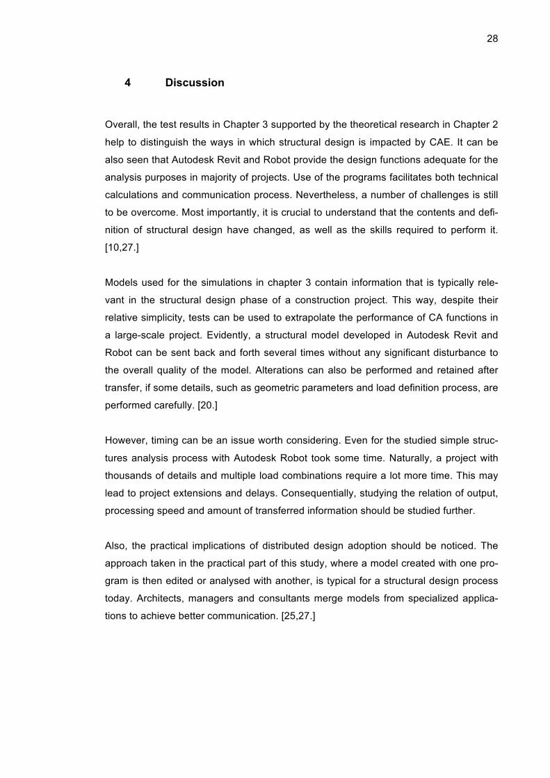
4 Discussion
Overall, the test results in Chapter 3 supported by the theoretical research in Chapter 2
help to distinguish the ways in which structural design is impacted by CAE. It can be
also seen that Autodesk Revit and Robot provide the design functions adequate for the
analysis purposes in majority of projects. Use of the programs facilitates both technical
calculations and communication process. Nevertheless, a number of challenges is still
to be overcome. Most importantly, it is crucial to understand that the contents and defi-
nition of structural design have changed, as well as the skills required to perform it.
[10,27.]
Models used for the simulations in chapter 3 contain information that is typically rele-
vant in the structural design phase of a construction project. This way, despite their
relative simplicity, tests can be used to extrapolate the performance of CA functions in
a large-scale project. Evidently, a structural model developed in Autodesk Revit and
Robot can be sent back and forth several times without any significant disturbance to
the overall quality of the model. Alterations can also be performed and retained after
transfer, if some details, such as geometric parameters and load definition process, are
performed carefully. [20.]
However, timing can be an issue worth considering. Even for the studied simple struc-
tures analysis process with Autodesk Robot took some time. Naturally, a project with
thousands of details and multiple load combinations require a lot more time. This may
lead to project extensions and delays. Consequentially, studying the relation of output,
processing speed and amount of transferred information should be studied further.
Also, the practical implications of distributed design adoption should be noticed. The
approach taken in the practical part of this study, where a model created with one pro-
gram is then edited or analysed with another, is typical for a structural design process
today. Architects, managers and consultants merge models from specialized applica-
tions to achieve better communication. [25,27.]

29
This system works well enough, provided that the synchronization of models is properly
organized. Such distributed design simplifies the delegation of tasks, which naturally
occurs in any construction project. As an outcome, deliverables are presented within
shorter period of time and their quality is typically better. The reason for that is the fact
that engineers work with narrowly targeted programs that offer exceptional results for a
limited number of tasks. An example of this is Autodesk Robot and its use for finite el-
ement analysis. [28,38,39.]
Distributed design still has some issues, mainly related to the openness and compati-
bility of design and its outputs. With Autodesk Revit and Robot, the integration process
takes place quickly and smoothly. Such results are expected from applications devel-
oped by the same company. However, many issues arise when applications were cre-
ated by different companies. A direct link is not always available and manual transfer of
a model requires high level of expertise in a number of areas: structural design, con-
struction management and programming. The transfer issue can currently be consid-
ered as pressing, and an express solution would be highly beneficial to many compa-
nies. [30.]
Finally, the roles of the structural engineer and designer are getting redefined, as new
skills become more and more essential and old ones are now looked at from a different
perspective. The main idea is that massive computations, which used to constitute the
body of structural engineer's work, are now done by of a machine. Constantly develop-
ing mechanisms of analysis and optimisation handle extremely complicated problems
better than humans could ever do. In turn, the ability to communicate the designer's
intent to a program and derive conclusions from numerical output provided by a com-
puter becomes invaluable, in order to successfully solve any structural design problem.
[27,31.]
At the same time, traditional skills and practices cannot be abandoned. The ability to
predict results and evaluate computations carried out by a computer application is es-
sential as well. In the case studies, the solutions to the problems were also calculated
normally and served as a reference point for the rest of the process. Yet in real projects
this scenario is impossible, so the reference point needs to be produced with approxi-

30
mate calculations in a very short time. This sort of proficiency requires exceptional
knowledge of traditional methods and an understanding of structures, setting high re-
quirements for future specialists. [31.]
Research performed in the course of writing this thesis shows that structural design
primarily benefits from the use of CAE methods. With the adoption of a distributed ap-
proach to design, facilitated by software applications that can be recurrently synchro-
nised, more precise and economical solutions become available. Although problems
with data exchange between computer programs of different developers are still to be
solved, the general impact of CAE can be considered positive both for the field and for
its specialists.

31
5 Conclusion
The intent of this paper is to identify those areas within structural design in construction
process that are most affected by the introduction of computational methods, and then
assesses the scale and consequences of these new developments. Data exchange is
one of the more obvious and, at the same time vital implications of CA structural de-
sign, thus it was studied particularly closely. [27.]
After defining structural design as part of a construction project, independent discipline
and technical approach to problem, it appears that CAE can be tied to structural design
in two major ways. First, computer software solves the problem of complex analysis
and optimization. FEA-based programs for structural analysis, such as Autodesk Ro-
bot, are an example of this. Second, since structural design serves as a part of a con-
struction project, developments in construction engineering typically affect the workflow
of a structural design process as well. Computer-enhanced modeling capabilities are a
relevant example for that, as they allow the design team to work more efficiently and
new ways of communication, presenting visuals and exchanging data. [13,25,31.]
The data exchange was studied more closely and showed to be worth the attention.
The quality of data transfer strongly affects the quality of final outputs and the time
frame of structural design. Some software applications, such as Autodesk Revit and
Robot, provide sufficient functions in that area. Their integration ensures a smooth in-
formation exchange and shows that a distributed design approach is developing in a
positive direction. Yet for other programs it may not be the case, as the synchronization
of products from different developers is typically more cumbersome. For this reason,
further investigation in data-processing issues, for instance, the manual definition of
transferred model may be pursued in future, becoming another fascinating area of re-
search. [38,39.]

32
6 References
1. Hibbeler RC. Structural analysis. 4th ed. Upper Saddle, NJ: Prentice-HAll, Inc; 1998.
2. Hung-Lin Chi, Xiangyu Wang, Yi Jiao. BIM-Enabled Structural Design: Impacts
and Future Developments in Structural Modelling, Analysis and Optimisation Processes. Archives of Computational Methods in Engineering 2015;22(1):135-151.
3. Simon HA. The Sciences of the Artificial. 3rd ed. US: MIT Press; 1996.
4. Kirsch U. Design-Orientated Analysis of Structures [online]. Secaucus, US:
Kluwer Academic Publishers; 2004. URL:http://site.ebrary.com.ezproxy.metropolia.fi/lib/metropolia/detail.action?docID=10066772. Accessed 28 March 2016.
5. Gray C, Hughes W. Building Design Management. GB: MPG Books Ltd; 2001.
6. Baldwin A, Bordoli D. Handbook for Construction Planning and Scheduling
[online]. Somerset, GB: Wiley; 2014. URL:http://site.ebrary.com.ezproxy.metropolia.fi/lib/metropolia/detail.action?docID=10860997. Accessed 29 March 2016.
7. Dym CL, Little P, Orwin EJ. Engineering design: a project-based introduction.
4th ed. US: John Wiley & Sons, Inc; 2014.
8. McGeorge D, Zou PXW. Construction Management [online]. Somerset, GB: Wiley-Blackwell, 2012. URL:http://site.ebrary.com.ezproxy.metropolia.fi/lib/metropolia/reader.action?docID=10657919. Accessed 29 March 2016.
9. Pahl G, Beitz W, Feldhusen J, Grote KH. Engineering Design: A Systematic
Approach. 3rd ed [online]. Springer-Verlag London; 2007. URL:http://link.springer.com.ezproxy.metropolia.fi/book/10.1007/978-1-84628-319-2/page/1 Accessed 28 March 2016.
10. Camilleri ML. Structural Analysis [online]. New York, US: Nova; 2010.
URL:http://site.ebrary.com.ezproxy.metropolia.fi/lib/metropolia/detail.action?docID=10681003. Accessed 29 March 2016.
11. Dabby R,Bedi A. Structure for Architects [online]. Hoboken, US: Wiley; 2012.
URL:http://site.ebrary.com.ezproxy.metropolia.fi/lib/metropolia/detail.action?docID=10546589. Accessed 29 March 2016.
12. Boswell K. Exterior Building Enclosures [online]. Somerset, US: Wiley; 2013.
URL:http://site.ebrary.com.ezproxy.metropolia.fi/lib/metropolia/detail.action?docID=10718824. Accessed 28 March 2016.

33
13. Construction Specifications Institute. CSI Construction Specifications Practice
Guide [online]. Hoboken, US: Wiley; 2011. URL:http://site.ebrary.com.ezproxy.metropolia.fi/lib/metropolia/detail.action?docID=10441468. Accessed 29 March 2016.
14. Megson T. Structural and Stress Analysis [online]. Jordan Hill, GB: Butterworth-
Heinemann; 2005. URL:http://site.ebrary.com.ezproxy.metropolia.fi/lib/metropolia/detail.action?docID=10138506. Accessed 17 March 2016.
15. McGeorge D, Zou PXW. Construction Management [online]. Somerset, GB:
Wiley-Blackwell, 2012. URL:http://site.ebrary.com.ezproxy.metropolia.fi/lib/metropolia/reader.action?docID=10657919. Accessed 29 March 2016.
16. Eynon J. The Design Manager's Handbook [online]. Somerset, GB: Wiley-
Blackwell; 2013. URL:http://site.ebrary.com.ezproxy.metropolia.fi/lib/metropolia/detail.action?docID=10546589. Accessed 29 March 2016.
17. Dym CL, Williams HE. Analytical Estimates of Structural Behavior [online]. Boca
Raton, US: CRC Press; 2012. URL:http://site.ebrary.com.ezproxy.metropolia.fi/lib/metropolia/detail.action?docID=10539449. Accessed 28 March 2016.
18. Hellesland J, Challamel NI, Casandjian C. Reinforced Concrete Beams, Col-
umns and Frames [online]. Somerset, US: Wiley-ISTE; 2013. URL:http://site.ebrary.com.ezproxy.metropolia.fi/lib/metropolia/detail.action?docID=10662558. Accessed 29 March 2016.
19. Maekawa K, Obikawa T, Yamane Y, Mechanical Design [online]. Butterworth-
Heinemann, Jordan Hill, GB; 2003. URL:http://site.ebrary.com.ezproxy.metropolia.fi/lib/metropolia/detail.action?docID=10169639. Accessed 28 March 2016.
20. Dym C. Principles of Mathematical Modeling [online]. Burlington, US: Academic
Press; 2004. URL:http://site.ebrary.com.ezproxy.metropolia.fi/lib/metropolia/detail.action?docID=10167048. Accessed 28 March 2016.
21. Kurrer KE. History of the Theory of Structures [online]. Hoboken, DE: Ernst &
Sohn; 2009. URL:http://site.ebrary.com.ezproxy.metropolia.fi/lib/metropolia/detail.action?docID=10355298. Accessed 29 March 2016.
22. Chen WF. Advanced analysis for structural steel building design. Frontiers of
Structural and Civil Engineering [serial online] 2008;2(3):189-196. URL:http://search.proquest.com.ezproxy.metropolia.fi/docview/251195850/BAE1D22476D645D7PQ/1?accountid=11363. Accessed 22 February 2016.

34
23. Zalka KA. Global Structural Analysis of Buildings [online]. US: CRC Press;
2000. URL:http://site.ebrary.com.ezproxy.metropolia.fi/lib/metropolia/detail.action?docID=10054256. Accessed 18 March 2016.
24. Abrishami S, Goulding J, Pour Rahimian F, Ganah A. Virtual generative BIM
workspace for maximising AEC conceptual design innovation: A paradigm of fu-ture opportunities [serial online] 2015;15(1):24-41. URL:http://search.proquest.com.ezproxy.metropolia.fi/docview/1641817647/8E2293CB6E5745A8PQ/1?accountid=11363. Accessed 22 February 2016.
25. Miettinen R, Paavola S. Beyond the BIM utopia: Approaches to the develop-
ment and implementation of building information modeling. Automation in Con-struction [serial online] 2014;43:84-91. URL:http://www.sciencedirect.com.ezproxy.metropolia.fi/science/article/pii/S0926580514000612. Accessed 22 February 2016.
26. Lino Maia, Meda P, Freitas JG. BIM Methodology, a New Approach - Case
Study of Structural Elements Creation. Procedia Engineering [serial online] 2015;114:816-823. URL:http://www.sciencedirect.com.ezproxy.metropolia.fi/science/article/pii/S1877705815016719. Accessed 22 February 2016.
27. Singh Vishal. BIM and systemic ICT innovation in AEC: Perceived needs and
actor's degrees of freedom. Construction Innovation [serial online] 2014;14(3):292-306. URL:http://search.proquest.com.ezproxy.metropolia.fi/docview/1658480446/8C5104B595D4D93PQ/1?accountid=11363. Accessed 22 February 2016.
28. Farr ERP, Piroozfar PAE, Robinson D. BIM as a generic configurator for facilita-
tion of customisation in the AEC industry. Automation in Construction [serial online] 2014; 45:119-125. URL:http://www.sciencedirect.com.ezproxy.metropolia.fi/science/article/pii/S092658051400123X. Accessed 22 February 2016.
29. Minho Oh, Jaewook Lee, Seung Wan Hong, Yongwook Jeong. Integrated sys-
tem for BIM-based collaborative design [serial online] 2015;58: 196-206. URL:http://www.sciencedirect.com.ezproxy.metropolia.fi/science/article/pii/S0926580515001582?np=y. Accessed 22 February 2016.
30. Ning Gu, Kerry London. Understanding and facilitating BIM adoption in the AEC
industry [serial online] 2010;19(8):988-999. URL:http://www.sciencedirect.com.ezproxy.metropolia.fi/science/article/pii/S0926580510001317. Accessed 18 February 2016.
31. Solihin W, Eastman C. Classification of rules for automated BIM rule checking
development [serial online] 2015;53:69-82. URL:http://www.sciencedirect.com.ezproxy.metropolia.fi/science/article/pii/S0926580515000370. Accessed 22 February 2016.

35
32. Moore JFA, editor. Monitoring Building Structures [online]. US: Routledge;
2003. URL:http://site.ebrary.com.ezproxy.metropolia.fi/lib/metropolia/detail.action?docID=10060693. Accessed 29 March 2016.
33. Akponanabofa Henry Oti, Walid Tizani. BIM extension for the sustainability ap-
praisal of conceptual steel design. Advanced Engineering Informatics [serial online] 2015;29(1): 28-46. URL:http://www.sciencedirect.com.ezproxy.metropolia.fi/science/article/pii/S1474034614000871?np=y. Accessed 22 February 2016.
34. Dalton SK, Atamtuktur S, Farajpour I, Hsein Juang. An optimization based ap-
proach for structural design considering safety, robustness, and cost.Engineering Structures [serial online] 2013;57:356-363. URL:http://www.sciencedirect.com.ezproxy.metropolia.fi/science/article/pii/S0141029613004525?np=y. Accessed 19 February 2016.
35. Davila Delgado JM, Hofmeyer H. Automated generation of structural solutions
based on spatial designs. Automation in Construction [serial online] 2013;35:528-541. URL:http://www.sciencedirect.com.ezproxy.metropolia.fi/science/article/pii/S0926580513001052. Accessed 19 February 2016.
36. El Hami A, Bouchaib R. Uncertainty and Optimization in Structural Mechanics
[online]. Somerset, US: Wiley-ISTE; 2013. URL:http://site.ebrary.com.ezproxy.metropolia.fi/lib/metropolia/detail.action?docID=10687764. Accessed 29 March 2016.
37. Arora JS. Optimization of Structural and Mechanical Systems [online]. River Edge, SG: WSPC; 2007. URL:http://site.ebrary.com.ezproxy.metropolia.fi/lib/metropolia/detail.action?docID=10255791. Accessed 29 March 2016.
38. Robot Structural Analysis Professional. Autodesk. [online].
URL:http://www.autodesk.com/products/robot-structural-
analysis/features/all/list-view. Accessed 18 May 2016
39. Revit. Autodesk. [online].
URL:http://www.autodesk.com/products/revit-family/overview. Accessed 18 May
2016
Appendix 1
1(3)
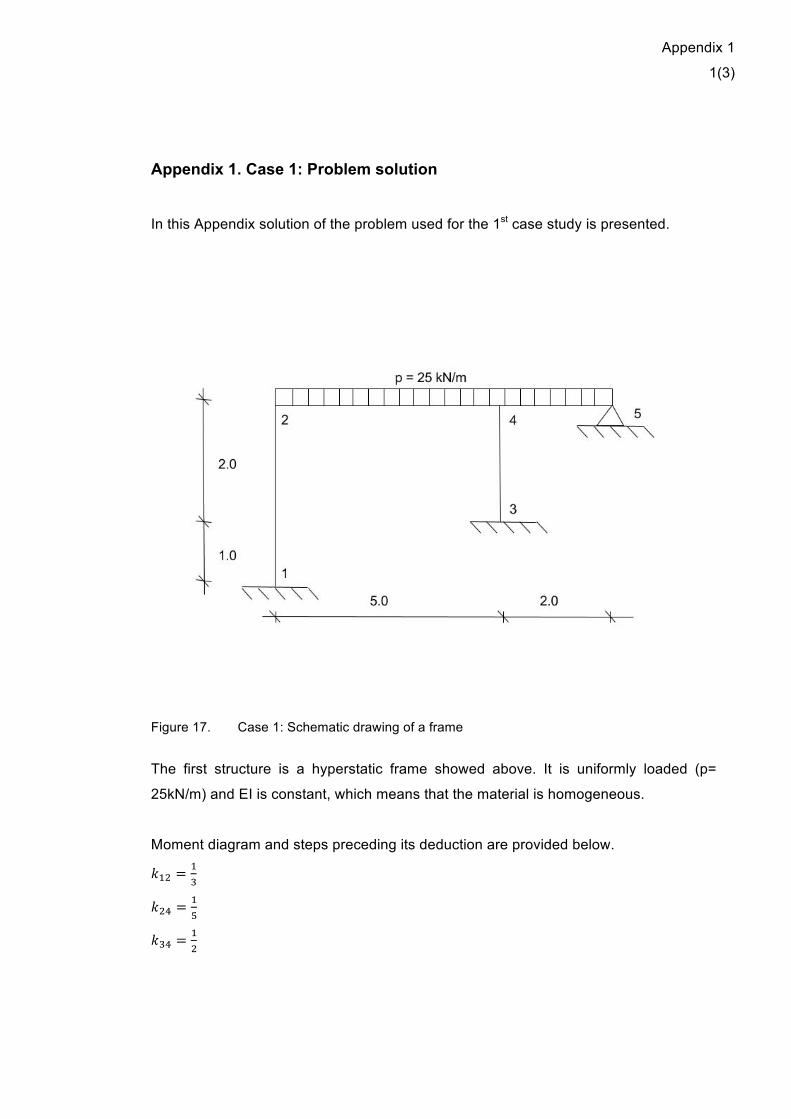
Appendix 1. Case 1: Problem solution In this Appendix solution of the problem used for the 1st case study is presented.
Figure 17. Case 1: Schematic drawing of a frame
The first structure is a hyperstatic frame showed above. It is uniformly loaded (p=
25kN/m) and EI is constant, which means that the material is homogeneous.
Moment diagram and steps preceding its deduction are provided below.
𝑘!" =!!
𝑘!" =!!
𝑘!" =!!

Appendix 1
2(3)
𝑘!" =!!∗ !!= !
!
𝜇!" =!!
!!!
!!= !
!
𝜇!" =!!
!!!
!!= !
!
𝜇!" =!!
!!!
!!!
!!= 0,18605
𝜇!" =!!
!!!
!!!
!!= 0,46512
𝜇!" =!!
!!!
!!!
!!= 0,34883
𝑀𝐾!" = − !!!
!"= − !"∗!"
!"= −52,084 𝐾𝑛𝑚 = −𝑀𝐾!"
𝑀𝐾!" =!!!
!= −12,5 𝑘𝑁𝑚
1 2 4 30,625 0,375 0,18605 0,46512 0,34884
-52,084 52,084 -12,516,27625 32,5525 19,5315 9,76575
-4,59076 -9,181521 -22,95356 -17,21517 -11,476781,434613 2,869225 1,721535 0,860768
-0,080073 -0,160146 -0,40036 -0,30027 -0,200180,025023 0,050046 0,030027 0,015014
-0,002793 -0,006983 -0,005237
17,73589 35,47177 -35,47177 53,38107 -23,3609 -30,02067 -11,67696
M12 M21 M24 M42 M43 M45 M34
𝑄!" =!!𝑝𝐿 − !!"!!!"
!= !
!25 ∗ 5 − !!",!"!!",!"
!= 58,92 𝑘𝑁
𝑥! =!!"!= 2,357 𝑚
𝑀!"# = 𝑀!" + 𝑄!"𝑥! −!!𝑝𝑥!! = 33,962 𝑘𝑁𝑚
𝑄!" =!!𝑝𝐿 − !!!"
!= !
!25 ∗ 2 − !!",!"
!= 40,01 𝑘𝑁
𝑀!"# = 1,98 𝑘𝑁𝑚

Appendix 1
3(3)

Appendix 2
1(8)
Appendix 2. Case 1: Steel frame design and analysis in Autodesk Robot Structural Analysis In this Appendix detailed procedure of the design and analysis via Autodesk Robot for
the 1st case study is presented.
Figure 18. Case 1, Autodesk Robot: Definition of axis 1

Appendix 2
2(8)
Figure 19. Case 1, Autodesk Robot: Definition of axis 2
Figure 20. Case 1, Autodesk Robot: Definition of elements 1

Appendix 2
3(8)
Figure 21. Case 1, Autodesk Robot: Definition of elements 2
Figure 22. Case 1, Autodesk Robot: Definition of supports 1

Appendix 2
4(8)
Figure 23. Case 1, Autodesk Robot: Definition of supports 2
Figure 24. Case 1, Autodesk Robot: Definition of loads 1

Appendix 2
5(8)
Figure 25. Case 1, Autodesk Robot: Definition of loads 2, load case selection
Figure 26. Case 1, Autodesk Robot: Definition of loads 3, load type
Appendix 2
6(8)
Figure 27. Case 1, Autodesk Robot: Definition of loads 4, magnitude and direction of a load
Figure 28. Case 1, Autodesk Robot: Definition of loads 5

Appendix 2
7(8)
Figure 29. Case 1, Autodesk Robot: running calculations 1
Figure 30. Case 1, Autodesk Robot: running calculations 2

Appendix 2
8(8)
Figure 31. Case 1, Autodesk Robot: presentation of results 1
Figure 32. Case 1, Autodesk Robot: presentation of results 1, moment diagram

Appendix 3
1(7)
Appendix 3. Case 1: Steel frame model integration between Revit and Ro-bot
In this Appendix detailed procedure of model integration between Autodesk Robot and
Revit or the 1st case study is presented.
Figure 33. Case 1, Autodesk Robot: establishing the link with Revit 1

Appendix 3
2(7)
Figure 34. Case 1, Autodesk Robot: establishing the link with Revit 2, properties selection
Figure 35. Case 1, Autodesk Robot: establishing the link with Revit 3
Appendix 3
3(7)
Figure 36. Case 1, Revit: model received from Autodesk Robot, plan view
Figure 37. Case 1, Revit: model received from Autodesk Robot, analytical model

Appendix 3
4(7)
Figure 38. Case 1, Revit: modification of the model 1
Figure 39. Case 1, Revit: modification of the model 2, reduction of the load
Appendix 3
5(7)
Figure 40. Case 1, Revit: establishing the link with Autodesk Robot
Figure 41. Case 1, Revit: integration process with Autodesk Robot 1

Appendix 3
6(7)
Figure 42. Case 1, Revit: integration process with Autodesk Robot 2
Figure 43. Case 1, Autodesk Robot: updated model with calculation messages

Appendix 3
7(7)
Figure 44. Case 1, Autodesk Robot: check of changes of updated model

Appendix 4
1(4)
Appendix 4. Case 2: Problem solution In this Appendix solution of the problem used for the 2nd case study is presented.
Figure 45. Case 2: Schematic drawing of a frame

Appendix 4
2(4)
Figure 46. Case 2: force method solution
𝛿!" =!!"
𝑀!𝑀!𝑑𝑠 = !!"!!!!"
𝑦! + 3𝑦! = !!"
!!!!! !!!! !!!!! !
!"−𝐿! + 3𝐿! =
− ! !!!!! !
!"!"−𝐿! + 3𝐿!
𝛿!! =!!"
𝑀!!𝑑𝑠 = !
!" !
!𝑠 𝑦!! + 𝑦!𝑦! + 𝑦!! + 𝑠𝑦!! +
!!𝑠𝑦!
! =
!!"
!!!!! !!!!!!!!!!!! !!!!!!!!!!!!
!
!= !!!!!!!!!!!!!!
!!"
𝛿!" =!!"
𝑀!𝑀!𝑑𝑠 = !!"!!!!!
𝑦! + 3𝑦! = !!"
!!!!! !!!! !!!!! !
!𝐻 = ! !!!!! !
!!"𝐻
𝛿!! =!!"
𝑀!!𝑑𝑠 = !
!" (𝑦! + !
! 𝑦!) = !
!" 𝐿! + 𝐿! ∗ 𝐻! + !
!𝐻 −𝐻 ! = !!"
𝐿! + 𝐿! ∗
𝐻! + !!𝐻
!

Appendix 4
3(4)
𝛿!" = 𝛿!" =!!"
𝑀!𝑀!𝑑𝑠 = !!"(!!
(𝑦! + 𝑦!)𝑦 + !!𝑠𝑦𝑦) =
!!"
!!𝐿! + 𝐿! 𝐿! − 𝐿! 𝐻 +
!!𝐻𝐿! −𝐻 = !
!!"( 𝐿!! − 𝐿!! 𝐻 − 𝐿!𝐻!)
𝛿!" + 𝑋!𝛿!! + 𝑋!𝛿!" = 0
𝛿!" + 𝑋!𝛿!" + 𝑋!𝛿!! = 0
𝛿!! 𝛿!"𝛿!" 𝛿!!
𝑋!𝑋!
= −𝛿!"−𝛿!"
!!!!!!!!!!!!!!
!!" 𝛿!"
!!!"
( 𝐿!! − 𝐿!! 𝐻 − 𝐿!𝐻!)
𝛿!"!!!"
( 𝐿!! − 𝐿!! 𝐻 − 𝐿!𝐻!) !!"
𝐿! + 𝐿! ∗ 𝐻! + !!𝐻
!
𝑋!𝑋!
=! !!!!! !
!"!"−𝐿! + 3𝐿!
! !!!!! !
!!"𝐻
𝑋! = 39,9 𝑘𝑁
𝑋! = 86,1 𝑘𝑁
𝐵! = 39.914 𝑘𝑁
𝐵! = 86.121 𝑘𝑁
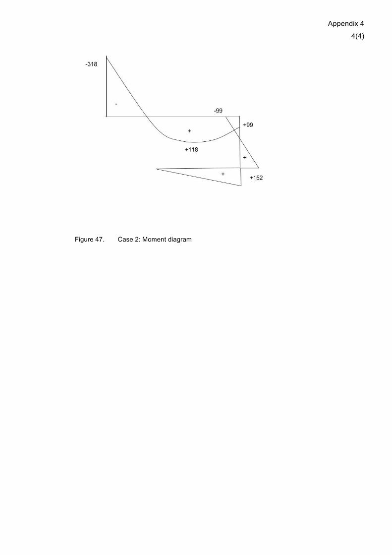
𝑀! = 𝐵! ∗ 𝐿! = 151.67 𝑘𝑁𝑚
𝑀!" = 𝐵! ∗ 𝐿! − 𝐵! ∗ 𝐿! = −98,08 𝑘𝑁𝑚 𝑀!" = 98,08 𝑘𝑁𝑚
𝑀! = 𝐵! ∗ 𝐿! + 𝐵! ∗ 𝐿! − !!! 𝐿! + 𝐿!
! = −317.645 𝑘𝑁𝑚
𝑄! = !!! 𝐿! + 𝐿! − !!!!!
!!!!!= !
!∗42 ∗ 5,5—!!"#,!"#!!",!"
!,!= 191,086 𝑘𝑁
𝑥! =!!!= 4,55 𝑚
𝑀!"# = 𝑀! + 𝑄!𝑥! − !!𝑝𝑥!
! = 117,04 𝑘𝑁𝑚
Appendix 4
4(4)
Figure 47. Case 2: Moment diagram

Appendix 5
1(7)
Appendix 5. Case 2: Steel frame design and analysis in Autodesk Robot Structural Analysis
In this Appendix detailed procedure of the design and analysis via Autodesk Robot for
the 2nd case study is presented.
Figure 48. Case 2, Autodesk Robot: definition of axis
Figure 49. Case 2, Autodesk Robot: prepared grid

Appendix 5
2(7)
Figure 50. Case 2, Autodesk Robot: definition of elements 1
Figure 51. Case 2, Autodesk Robot: definition of elements 2

Appendix 5
3(7)
Figure 52. Case 2, Autodesk Robot: definition of supports 1
Figure 53. Case 2, Autodesk Robot: definition of supports 1

Appendix 5
4(7)
Figure 54. Case 2, Autodesk Robot: definition of loads 1, load case selection
Figure 55. Case 2, Autodesk Robot: definition of loads 1, load type selection
Appendix 5
5(7)
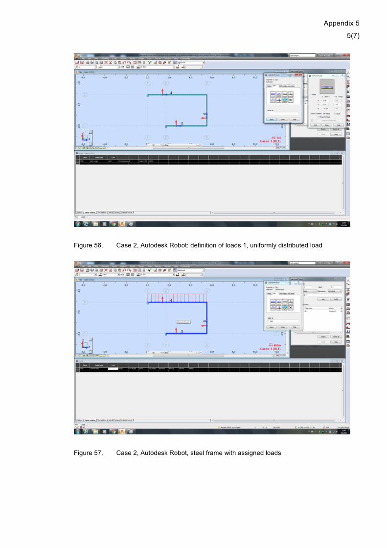
Figure 56. Case 2, Autodesk Robot: definition of loads 1, uniformly distributed load
Figure 57. Case 2, Autodesk Robot, steel frame with assigned loads

Appendix 5
6(7)
Figure 58. Case 2, Autodesk Robot: analysis
Figure 59. Case 2, Autodesk Robot: moment diagram with table for reactions’ magnitudes

Appendix 5
7(7)
Figure 60. Case 2, Autodesk Robot: final moment diagram

Appendix 6
1(10)
Appendix 6. Case 2: Steel frame design and analysis in Autodesk Robot Structural Analysis In this Appendix detailed procedure of model integration between Autodesk Robot and
Revitf or the 2nd case study is presented.
Figure 61. Case 2, Autodesk Robot: establishing the link with Revit 1
Figure 62. Case 1, Autodesk Robot: establishing the link with Revit 2, properties selection

Appendix 6
2(10)
Figure 63. Case 2, Autodesk Robot: establishing the link with Revit 3, properties selection
Figure 64. Case 2, Revit: project definition
Appendix 6
3(10)
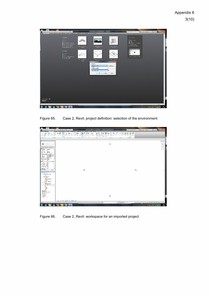
Figure 65. Case 2, Revit: project definition: selection of the environment
Figure 66. Case 2, Revit: workspace for an imported project

Appendix 6
4(10)
Figure 67. Case 2, Revit: import process of the Robot project
Figure 68. Case 2, Revit: imported Robot model

Appendix 6
5(10)
Figure 69. Case 2, Revit: front view of the model
Figure 70. Case 2, Revit: adjustment of a model element 1

Appendix 6
6(10)
Figure 71. Case 2, Revit: adjustment of a model element 2
Figure 72. Case 2, Revit: input of new load values

Appendix 6
7(10)
Figure 73. Case 2, Revit: model is updated according to new loads
Figure 74. Case 2, Revit: establishing a link with Robot

Appendix 6
8(10)
Figure 75. Case 2, Revit: selection of exported properties
Figure 76. Case 2, Revit: access permission request

Appendix 6
9(10)
Figure 77. Case 2, Revit: integration procedure
Figure 78. Case 2, Robot: updated model

Appendix 6
10(10)
Figure 79. Case 2, Robot: analysis of the updated model
Figure 80. Case 2, analysis results for the updated model