
Computer-aided boiler design - inive.orgclima2000\1997\P282.pdf · PT Gaz de France, R & D Division...
21
Computer-aided boiler design Patricia BRIANDTP * PT - Philippe PONTIGGIAP * P UKeywords U : modelling, simulation, control USummary U: In 1993, the R & D Division launched the IntelChaud project with a view to improving the comfort provided by individual gas-fired boilers used for domestic hot water production. This study was conducted in partnership with two French boiler manufacturers and was therefore applied to two particular cases. The work performed for this study has led to substantial improvements in boiler control through the use of sophisticated numerical control systems. To make up for inadequate instantaneous power, a smart management system involving the combination of a « boiler + storage tank » was developed. The robustness of the control laws was tested by simulation. The management law for the « boiler + tank » unit was established on a simulator. To this end, fine models of boilers and storage tanks were developed on ALLAN.Simulation. This article describes how the simulators were used both to test the pertinence and robustness of the control and management laws that we developed and to study the potential domestic hot water production performance gains that could be obtained by making technical modifications to the systems under study. Introduction Though instantaneous gas-fired boilers provide an economical solution to domestic water heating needs, the heating comfort provided is often judged inadequate by users [1]. Four major problems [2], all sources of discomfort, are commonly encountered with the individual gas boilers currently on the market: TP * PT Gaz de France, R & D Division 361, avenue du Président Wilson B.P. 33 F-93211 La Plaine Saint-Denis Cedex email : patricia.briand@edfgdf.fr - philippe.pontiggia@edfgdf.fr 1
Transcript of Computer-aided boiler design - inive.orgclima2000\1997\P282.pdf · PT Gaz de France, R & D Division...

Computer-aided boiler design
Patricia BRIANDTP
*PT - Philippe PONTIGGIAP
*P
UKeywordsU : modelling, simulation, control USummaryU:
In 1993, the R & D Division launched the IntelChaud project with a view to improving the comfort provided by individual gas-fired boilers used for domestic hot water production. This study was conducted in partnership with two French boiler manufacturers and was therefore applied to two particular cases.
The work performed for this study has led to substantial improvements in boiler control through the use of sophisticated numerical control systems. To make up for inadequate instantaneous power, a smart management system involving the combination of a « boiler + storage tank » was developed. The robustness of the control laws was tested by simulation. The management law for the « boiler + tank » unit was established on a simulator. To this end, fine models of boilers and storage tanks were developed on ALLAN.Simulation.
This article describes how the simulators were used both to test the pertinence and robustness of the control and management laws that we developed and to study the potential domestic hot water production performance gains that could be obtained by making technical modifications to the systems under study.
Introduction
Though instantaneous gas-fired boilers provide an economical solution to domestic water heating needs, the heating comfort provided is often judged inadequate by users [1].
Four major problems [2], all sources of discomfort, are commonly encountered with the individual gas boilers currently on the market:
TP
*PT Gaz de France, R & D Division
361, avenue du Président Wilson B.P. 33 F-93211 La Plaine Saint-Denis Cedex email : [email protected] - [email protected]
1

- the hot water takes too long to arrive at the tap. This problem is partly linked to boiler startup (which may in some cases take around one minute and give rise to temporary water overheating);
- water temperature is unstable when the draw-off rate varies, hence the "icy shower" often received when two or more taps are turned on successively;
- "temperature peaks" caused by severe water overheating may occur when the boiler is restarted. This problem is due to the overheating of water remaining in the heat exchanger after the boiler has been turned off;
- there is inadequate instantaneous power, which means that the boiler is unable to heat the water to the required temperature when draw-off rates are high.
To promote the development of boilers capable of ensuring enhanced user comfort, in 1993 the Gaz de France R & D Division launched the IntelChaud project in partnership with two French boiler manufacturers.
Context of the study
The problems detailed above were all studied as part of this project.
The studies were performed on two boilers currently available on the market, referred to here as « first » and « second » for reasons of confidentiality.
To improve water temperature stability and reduce temperature peaks after restarting, the existing analogue control systems on these boilers were replaced by more sophisticated numerical control units.
To make up for inadequate instantaneous power and reduce the time required for starting domestic hot water production, each boiler was connected to a storage tank and placed under the control of smart management systems. This substantially increased the quantity of water initially available in the tank. (The "boiler + tank" assemblies will be referred to as the « heaters »).
The control and management laws were developed and tested on simulators in parallel with an experimental study. Boiler and heater simulators were developed on ALLAN.TP
TMPTSimulation for both cases under study. They were used to test the
robustness of the control laws developed by us when confronted with disturbances in operating conditions or with defects or modifications in the sensors and actuators.
Several types of control were tested: PID, internal model and fuzzy logic control, with or without measurement of the hot water draw-off rate. The performance of these different control methods proved to be more or less equivalent, provided that they were correctly adjusted. Measurement of hot water flow rate is only justified if the boiler inertia is low enough to counteract rapidly the effects of flow-rate variation.
The results obtained for instantaneous hot water production are very encouraging.
TP
TMPT ALLAN. is a registered trade-mark of Gaz de France
2

Thanks to numerical control, the temperature peaks at boiler startup were eliminated and the water temperature at the boiler outlet stabilized three times more quickly. The amplitude of temperature peaks caused by hot water flow-rate variations was divided by three.
According to a survey carried out by the R & D Division on users' expectations for domestic hot water comfort (in terms of temperature stability, duration of temporary temperature fluctuations and quantity of hot water available), the use of the numerical control systems developed by us leads to a substantial increase in the level of user satisfaction, especially as regards temperature fluctuations due to flow disturbances, by far the most annoying problem. In the two cases under study, user satisfaction remains above 90% when flow rate is increased (as compared to around 60% with analogue control) and above 75% following a drop in hot water flow rate (compared to 50% initially) [3].
However, these results are affected by the technical limitations of the boilers, in particular by their maximum output and their output adjustment range.
Coupling with a storage tank increases satisfaction in all cases but is more costly for the user.
Following this initial study, we used simulation techniques to assess the effects of certain technical boiler modifications on the quality of instantaneous domestic hot water production.
For the case of storage water heating, we also sought to decrease the tank volume in order to make the final product more economical and attractive for users thanks to its more compact design.
After a brief description of the simulators, we will present some of the results of robustness and technical modification tests already performed with the boiler and heater simulators. We will conclude by indicating the planned follow-up to this study.
Modelling
Two simulators of boilers and of boilers associated with a storage tank with or without internal heat exchanger were developed on ALLANP
TMP.Simulation which is a
modeller devised by Gaz de France and developed with the help of CISI and a contribution of Dassault Data Services.
Currently, it can be coupled either with CISI's NEPTUNIX solver or with ADASSL, a customized version of DASSRT.
We used the modelling procedure developed specifically by Gaz de France for this tool.
In this section, we will present briefly ALLANP
TMP.Simulation, the NEPTUNIX
solver (the one used for this study), the modelling approach used and, as an illustration, the simulator of a boiler and of a heater.
UALLANUPU
TMUPU.Simulation [4]U
3

ALLAN. is a general purpose tool which uses "boxes and strings" representation (multi-variable, unoriented block diagrams). All or part of the models or analyses established at a previous time and stored in a library can be reused whenever necessary.
It makes use of interactive graphics for the symbolic description of the systems studied and frees the user from the programming work necessary for the implementation of general resolution and processing programs. In this sense, this software is a "modeller", i.e., a model description and management tool. Its current application aims to simulate technical systems by the use of "solver" programs. These programs are able to solve mathematical problems (systems of algebraic and differential equations) transmitted by the modeller.
As a general rule, the complexity of the system makes it convenient, if not imperative, to break it down into elements. These elements are called models.
The models whose operation is represented by equations/events/procedural text are called simple models.
For reasons of modularity, for reuse or for a specific study, several models can be combined permanently in a box. These models, which define sub-systems or the technical system under study, are called compound models. They can, of course, be made up from other compound models, thus forming large-scale systems.
Once the technical system has been described, with or without assembly of simple
or compound elements taken from the library or defined for the occasion, a translator produces, in the syntax of the solver, the text corresponding to the system of equations to be solved. A compilation stage transforms this text into an executable code, the simulator. The simulator can be "encapsulated" and provide elements for connection to the exterior, parameters or variables of the technical system. It is then possible to operate the simulator generated and process the simulation results.
UNeptunix solver [5]U
NEPTUNIX is a software package for simulation of systems described by a set of algebraic and differential equations:
F (x, x', p, l, t) = 0
where t is the independent variable, x a set of continuous variables, x' = dx/dt, p a set of parameters and l a set on non-continuous variables. The function F may be non-linear. The software thus accepts formulations in the form of implicit equations of processes which may contain discontinuities.
UThe modelling approach [6]
The SEPA (Suivi d'une Etude Pour ALLAN.Simulation) modelling approach has been developed at Gaz de France. It guides the modeller through the following stages:
4

- drafting of the modelling specifications based on requirements provided by the client commissioning the study. These specifications include a description of the system to be modelled and the question raised by the client;
- breakdown, during which the system to be modelled (main model) is analysed and broken down into sub-systems (compound models) and then into basic elements (simple models), simple enough for the modeller to fully apprehend. This breakdown may be functional, topological, technological or phenomenological.
- writing, i.e., expression in ALLAN language of the behaviour of the simple models obtained during the breakdown stage;
- validation of simple models and then of compound models, up to validation of the main model. Validation may be analytical, qualitative, numerical or experimental.
UThe first boiler simulator U
The first boiler is an individual dual-service gas boiler, i.e., it provides both domestic hot water and space heating water from the same appliance. In both cases, hot water production is instantaneous.
The main water/flue gas heat exchanger (figure 1) crossed by the heating water circuit is located above the burner and is heated directly by the flue gases. A water/water plate heat exchanger transfers heat from the space heating circuit to the domestic water heating circuit. A three-way bypass valve directs the heating water either to the radiators (space heating mode) or to the plate heat exchanger (domestic water heating mode). The boiler is not equipped with a flue gas extractor and must therefore be connected to a flue.
The simulator reproduces the operation of the boiler associated with the numerical control unit, which enables it to adjust the domestic hot water temperature to the desired setting, and with the instrumentation installed in parallel on the test rig.
For the breakdown of the complete system defined above, we gave priority to a technological breakdown method which separates out the constituent components of the boiler (burner, heat exchangers, circulator, valve, etc.). This breakdown makes it easy to replace component models during operation of the simulator. Moreover, the models developed can easily be reused in other contexts.
The breakdown of the boiler is presented in tree form in figure 2.
5

Circulator
Cold water inletDomestic hot
Heating water return
Burner
Heating water
Gas solenoid valve
Main heat exchanger
Plate heat exchanger
valvebypass
outlet water outlet
Figure 1: operating principle of the boiler
6

Niveau 1 - functional
Niveau 2 - technical 1
Niveau 3 - technical 2
Niveau 5 - phenomenological
BOILER
GAS SUPPLY HEATING WATER PRODUCTION
Niveau 4 - topological
CONTROL
CONVECTION
DOMESTIC HOT WATER
PRODUCTION
PIPINGMEASUREMENT INSTRUMENTS
HEAT
FRESH AIR INLET
SECTIONS
MEASUREMENT
DISTRIBUTION
DIVERGING3-WAYCOMBUSTION
FLUEBURNER
COILS
COMBUSTION
DIVERGING MIXER
RADIATION
CHAMBERWALL MIXER
(FLAME)
HEATING WATER
EXCHANGER PIPING
GASESHEAT
EXCHANGER
MEASUREMENT INSTRUMENTS
CIRCULATOR
TUBE
TUBE
SECTIONS SECTIONS
FLUID TRANSPORT
CONDUCTION WITHOUT
NATURAL FORCED CONVECTION CONVECTION
INERTIASOLIDNODES
FLUID TRANSPORTEQUIVALENTWATER+METAL
CONDUCTION WITH
INERTIA NATURAL CONVECTION
TRANSPORTCONVECTION
FORCED FLUID
VALVE
INSTRUMENTS
SOLIDNODES
CONDUCTION WITHOUTINERTIA
CONVECTIONFORCED
RADIATION
FLUID TRANSPORT
Figure 2: breakdown tree of the boiler
7

The second heater simulator
Each boiler simulator was coupled with a model of a storage tank with or without internal heat exchanger. For this purpose, the boiler simulators were intrinsically reused.
Here, we will simply present (figure 3) the assembly of the second heater comprising the second boiler (equipped with a single heat exchanger crossed both by the domestic hot water and the space heating water) associated with a numerical control unit and a direct regeneration tank, i.e., without internal heat exchanger (during the regeneration phase, the hot water from the boiler is sent directly to the tank via the regeneration pump mounted on the circuit).
The boiler and the tank are connected in series.
The flow rate value is limited through the boiler in order to maintain an adequate level of water outlet temperature. Then, when draw-off rates are higher than the maximum value of flow rate through the boiler, the V valve make it possible to admit the complementary cold water inlet flow rate directly in the tank.
Vuser represents the domestic hot water draw-off tap.
Only the domestic hot water production circuits are represented in figure 3.
The modelled system also includes the system for management of domestic hot water draw-off configurations.
8

Tank
V
Pump
Cold water inlet
Regeneration inlet
Draw-off outlet
Cold water inlet
Regeneration outlet
Boiler
Vuser
Figure 3: operating principle of the heater
Numerical control system robustness tests [7]
The PID temperature control of domestic hot water leaving the boiler was tested on the first boiler simulator. The hierarchical and technical breakdown of the boiler model made it easy for us to study the behaviour of the control system when confronted with localized physical and technical variations in the process.
As an illustration, we will present some of these robustness tests performed for three types of disturbance:
- variations in operating conditions : scaling of the secondary circuit and silting of the primary circuit;
- defects in the sensors and switches : longer response time by the domestic hot water temperature sensor and primary flow rate instability;
- modifications in boiler settings : lower minimum burner output.
In addition, further tests were performed concerning cold water temperature variations at the boiler input, faulty domestic hot water temperature measurements (measurement noise, measurement linearization and quantification), faulty gas-valve positioning (white noise on position and incorrect valve hysterisis curve), and other modifications in boiler settings (interlock time, ignition delay).
9

They enabled us to predict the behaviour of the control system throughout the boiler life cycle and to determine specifications concerning acceptable tolerances for boiler instrumentation.
Robustness with respect to operating conditions
Effect of domestic hot water circuit scaling
One of the main processes affecting a boiler during its service life is the scaling of the domestic hot water heat exchanger [8]. The scale deposit reduces the internal diameter of the hot water pipes, increases the speed of water flow at a given flow rate and raises the thermal resistance of the heat exchanger.
Scale formation resulting in a 20, 50 and 75% reduction in the initial cross section of flow of the hot water pipes was simulated.
We observe (figure 4) that scaling of the domestic hot water heat exchanger has very little effect on the control system, a positive result as regards its robustness. The main effect of scaling (figure 5) is a temperature increase in the primary circuit to offset the increased thermal resistance, as the control system seeks to provide the necessary thermal flow. There is a risk that the water will boil in the exchanger. For this reason, an overheating safety device (deactivated for the simulationTP
2PT ) shuts off
the burner at 95°C.
If the domestic hot water temperature variations during startup and sudden flow rate fluctuations is analysed in more detail, we note that the control system reacts more slowly as the amount of scale increases.
TP
2PT Values above 100°C are given for information only, since boiler behaviour with boiling water is not
modelled by the simulator.
10

no scaling20% scaling50% scaling75% scaling
DHW outlet temperature (°C)
Time (s)
DHW flow rate (l/mn)
Figure 4: effect of scaling on the behaviour of the control system.
no scaling20% scaling50% scaling
75% scaling
DHW temperature in the primary circuit (°C)
Time (s) Figure 5: effect of scaling on temperature in the primary circuit
11

Moreover, minor domestic hot water temperature oscillations begin to occur when the heat exchanger contains large scale deposits (75%). In any case, by this time descaling is urgent since the temperatures in the primary circuit are dangerously high.
Lastly, to obtain domestic hot water at the desired temperature despite scaling of the heat exchanger, gas consumption must be increased. For the test shown in figure 4, we observed that consumption rose by up to 6% for an exchanger with 75% scaling.
Effect of primary circuit silting
Substances may also be deposited on the primary circuit walls. "Sludge" deposits may include scale, though in smaller quantities than in the domestic hot water circuit since the water is not changed, or particles due to corrosion. The resulting silting of pipes reduces the flow rate in the primary circuit.
Unlike the problem of scale, little information is available for the simulation of primary circuit silting: we do not know the thermal conductivity of the "sludge", the thickness of the "sludge" layers or the pressure losses in the primary circuit (with and without silting).
We made a qualitative analysis of primary circuit silting, assuming that 10% silting leads to a 10% drop in primary flow rate and that sludge conductivity was comparable with that of scale.
By simulating 10% silting of the primary circuit under these conditions (figure 6), we observed that the control system is not very sensitive to silting. As in the case with scaling, only the temperature in the primary circuit increases. This increase becomes greater as the flow rate in the primary circuit decreases (which was not the case for scale).
HW temperature in theprimary circuit (°C)
DHW temperature (°C)
no silting10% silting
Time (s) Figure 6: effect of primary circuit silting on control.
12

13

Faulty sensors and actuators
Longer response time of the domestic hot water temperature sensor
It is always important to test the sensitivity of the control system with respect to the choice of sensors and actuators. Here, the effect of a modification in response time τ of the sensor measuring water temperature at the boiler outlet is observed in simulation.
DHW temperature (°C)
DHW flowrate (l/mn)
Time (s)
τ = 1 s (nominal)τ = 2 sτ = 5 s
Figure 7: behaviour of the control system for different sensor response times
DHW temperature (°C)
Time (s)
DHW flowrate (l/mn)
14

Figure 8: behaviour of the readjusted control system with the slow sensor (τ = 5s)
We can see (figure 7) that the control system tolerates variations of between 1 and 2 seconds in the sensor response time. It is therefore robust with respect to sensor production disparities.
On the other hand, if the response time is radically modified (by choosing a new sensor for example), the PID control must be revised (figure 8) to prevent system oscillation.
Flow rate instability in the primary circuit
We thought it would be interesting to study the behaviour of the control system when confronted with pump malfunctions affecting the water flow rate in the primary circuit.
We first simulated a large (-15%) and brief (≈ 3s ) flow-rate reduction to represent sporadic pump seizing. We observe that this does not destabilize the control system, despite a substantial rise in outlet temperature (figure 9).
DHW temperature (°C)
HW flowrate in the primary circuit (l/mn)
Boiler outlet (kW)
Time (s) Figure 9: effect of sporadic primary circuit pump seizing
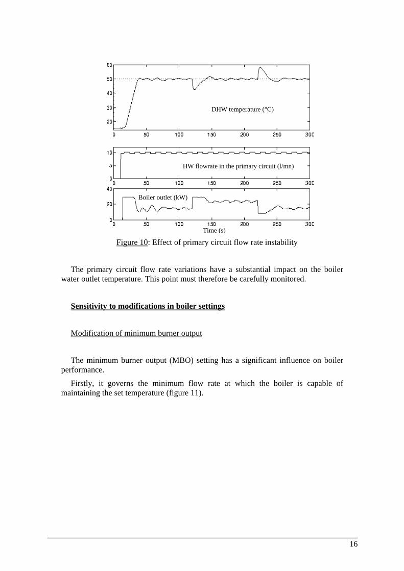
We then switched the flow rate, at a moderate frequency (every 8 s), between two values which differ by 5% (figure 10). This represents a more-or-less cyclical primary circuit flow rate disturbance.
The temperature starts to oscillate at a frequency identical to that of the primary circuit flow rate. The amplitude of oscillations is considerable and increases rapidly if the primary circuit flow rate fluctuations are large.
15
DHW temperature (°C)
HW flowrate in the primary circuit (l/mn)
Boiler outlet (kW)
Time (s) Figure 10: Effect of primary circuit flow rate instability
The primary circuit flow rate variations have a substantial impact on the boiler water outlet temperature. This point must therefore be carefully monitored.
Sensitivity to modifications in boiler settings
Modification of minimum burner output
The minimum burner output (MBO) setting has a significant influence on boiler performance.
Firstly, it governs the minimum flow rate at which the boiler is capable of maintaining the set temperature (figure 11).
16

MBO = 8 kWMBO = 5 kWMBO = 10 kW
DHW temperature (°C)
DHW flowrate (l/mn)
Time (s) Figure 11: boiler behaviour at 3, 2 and 1 l/mn for different minimum burner output
settings
Secondly, the lower the minimum output, the faster any decrease in draw-off rate can be counteracted. This can be seen on the second jump on figure 12.
DHW temperature (°C)
Boiler output (kW)
MBO = 8 kWMBO = 5 kWMBO = 10 kW
Time (s) Figure 12: flow rate jumps for different minimum burner outputs
17

Similarly, if the maximum available burner output was higher, the positive hot water flow rate jumps could be counteracted more rapidly. The graph below (figure 13) illustrates the advantage of having a high burner output with a wide adjustment range (AR). Here we simulated the case of a burner with an output range of 0.5 kW to 44 kW.
AR = 8 - 29 kWAR = 0.5 - 44 kW
DHW temperature (°C)
Boiler output (kW)
Time (s) Figure 13: boiler behaviour with a 0.5 - 44 kW burner
Finding an optimum tank volume
The association of a storage tank and an instantaneous boiler further enhances user comfort while reducing the time required for starting domestic hot water production (the hot water transport time in the pipes remains incompressible), by increasing the quantity of water available for high draw-off rates (stored hot water) and by reducing the number of residual temperature peaks. It also eliminates the need for a threshold boiler flow rate below which a safety system prevents the burner from igniting since the water produced would be too hot.
A simulation study enabled us to develop a management system based on the idea that we could use the two main properties of a tank :
- first, the domestic hot water storage possibility;
- second, the tank, when connected in series with the boiler, makes it possible to smooth the water temperature peaks from the boiler.
We managed to obtain these two properties together, using the tank as follows :
- the hot water enters the tank at its upper part;
18

- the cold water enters the tanks at its lower part;
- the domestic hot water is drawn off from the lower part of the tank only when the boiler alone is not able to produce the required flow rate.
Several draw-off scenarios were tested.
We were thus able to show that rational management of instantaneous and storage water heating led to a doubling of useful tank volume (quantity of hot water that can be drawn off at a given temperature).
The curves in figure 14 illustrate a simulated draw-off sequence during which the setting of the domestic hot water temperature is 55 °C.
Draw-off tap opening (%)
DHW outlet temperature - boiler without tank (°C)
DHW outlet temperature - boiler with tank (°C)
Figure 14: simulated draw-off sequence
As regards comfort, we note on this figure that the water temperature at the heater outlet is very stable, whereas the boiler alone provides a less satisfactory level of comfort (late hot water, peaks at hot startup, temperature drops during high-rate draw-offs and temperature rises or drops with draw-off rate variations).
Conversely, the simulation indicates that by modifying the parameter defining tank volume, 90% of users will be satisfied in practically all cases by a system associating this same boiler with a tank half the size of current tanks. Confirmed by late experiments, this solution is encouraging since its opens up prospects for the development of compact high-performance appliances.
19

Conclusion
This study has shown that the use of numerical control systems in individual gas boilers leads to substantial improvements in user comfort for domestic hot water production.
The control options were themselves limited by the technical limitations of the boilers and further comfort gains were obtained by associating a storage tank with the unmodified instantaneous boiler.
We have shown that intelligent management of instantaneous and storage water resources makes it possible to reduce the volume of this tank while maintaining a very high level of user comfort.
The use of simulation in this study enabled use to understand more clearly the operation of the processes to be controlled.
The simulators were then used to test the control and management laws developed by us under operating conditions which are impossible or difficult to recreate experimentally and to test technical modifications which would otherwise be unfeasible, while exploiting all the qualities of a standard software test bench (especially its availability, adaptability and its capacity to reproduce identical environmental conditions, a very useful feature during comparison of control sequences).
The two key advantages of ALLAN.Simulation in this study were the capitalization of the models developed (use of models in two applications, reuse of boiler models for the construction of heater models) and the hierarchical composition of simulators (which meant that they could be rapidly adapted to test the desired technical modifications).
A further simulation study will now be launched, based on the boiler simulators, to test the effect of new technical developments which aim to enhance the performance of these boilers and thus do away with the need for a storage tank. Our particular objective is to study burner/exchanger couples by adapting the control system to each technical development and thus to make optimum use of each proposed solution. This is an overall design approach
Bibliography
[1] « Production d’eau chaude instantanée à partir de chaudières murales », J.J. TRUET Réf : L’installateur - n°503 - Sept. 1988
20

[2] « Individual boiler of the future », E. BRACONNIER, P. PONTIGGIA, V. EM, M. JIMENEZ GDF-DR Réf : IEA International Conference on Natural Gas technologies - Berlin - Sept. 1996 [3] « Regulation system for Domestic Hot Water Temperature » G. BIAGINI & R. BARTOLOZZI Réf : Italian Patent n° IT 2054486 [4] « ALLAN.P
TMPSimulation - Release 3.1 Description”,
A. JEANDEL, GDF - DR - DéGIMA - GSA Réf : M.DéGIMA.GSA 1887 AJ/DG [5] « NEPTUNIX : langage de description de modèle », CISI, octobre 1988 [6] ”Guide de Suivi d’une Etude pour ALLAN.Simulation - Version 2.0”, Alexandre JEANDEL GDF - DR - DéGIMA - GSA Eric LARIVIERE CISI pour GDF - DR - DéGIMA - GSA Réf.: M.DéGIMA.GSA888.AJ/TA [7] « Robustesse d’un régulateur PID installé sur une chaudière murale à gaz - Etude en simulation » Philippe PONTIGGIA GDF - DR - DéGIMA - GSA Réf : M.DéGIMA.GSA1661.PP/TA [8] « Méthodes automatiques de détection des défauts et dérives des installations
de chauffage» X. LI & J-C. VISIER Réf : Cahiers du CSTB n°2853 -Déc. 1995
21