COMPUTER-AIDED ANALYSIS OF BALANCING OF MULTI-CYLINDER...
45
1 COMPUTER-AIDED ANALYSIS OF BALANCING OF MULTI-CYLINDER INLINE AND V ENGINES Project report submitted in partial fulfillment Of requirement for degree of Bachelor of technology In Mechanical engineering By RAHUL SHARMA ROLL NO: 10603043 Department of Mechanical Engineering 2009-2010
Transcript of COMPUTER-AIDED ANALYSIS OF BALANCING OF MULTI-CYLINDER...

1
COMPUTER-AIDED ANALYSIS OF BALANCING OF
MULTI-CYLINDER INLINE AND V ENGINES
Project report submitted in partial fulfillment
Of requirement for degree of
Bachelor of technology
In
Mechanical engineering
By
RAHUL SHARMA
ROLL NO: 10603043
Department of Mechanical Engineering
2009-2010
2
COMPUTER-AIDED ANALYSIS OF BALANCING OF
MULTI-CYLINDER INLINE AND V ENGINES
Project report submitted in partial fulfillment
Of requirement for degree of
Bachelor of technology
In
Mechanical engineering
By
RAHUL SHARMA
ROLL NO: 10603043
Under the guidance of
Prof. N.KAVI
3
Department of Mechanical Engineering
2009-2010
National institute of Technology
CERTIFICATE
This is to certify that the project entitled “COMPUTER-AIDED ANALYSIS OF
BALANCING OF MULTI-CYLINDER INLINE AND V ENGINES” by Rahul
Sharma has been carried out under my supervision in partial fulfillment of the
requirement of the Degree of Bachelor of Technology during session 2009-10 in
department of Mechanical engineering, National Institute of Technology, Rourkela
and this work has not been submitted elsewhere for a Degree.
Place: Rourkela Prof. (Dr.) N. Kavi
Date: Professor
Department of Mechanical Engineering
National Institute of Technology, Rourkela
4
ACKNOWLEDGEMENT
I wish to express my heartfelt thanks and deep gratitude to Prof. N. Kavi for his
excellent guidance and whole hearted involvement during my project work. I am also
indebted to him for his encouragement, affection and moral support throughout the
project. I am also thankful to him for his time he has provided with practical
guidance at every step of the project work.
I would also like to sincerely thank Prof. K.P.Maity who with their valuable
comment and suggestion during the viva voce helped me immensely. I would also
like to thank him because they was the one who constantly evaluated, corrected me
and had been the guiding light for me.
Lastly, I would like to express my deepest thanks to my friends who were always
there to help me whenever I was in any kind of problem during my project work.
Rahul Sharma
5
CONTENTS
ABSTRACT ....................................................................................................................................... 1
INTRODUCTION ............................................................................................................................. 2
LITERATURE REVIEW ................................................................................................................. 3
THEORY ............................................................................................................................................ 4
INLINE ENGINE ANALYSIS ......................................................................................................... 9
V-ENGINE ANALYSIS .................................................................................................................. 19
RESULTS AND DISCUSSION ...................................................................................................... 35
CONCLUSION ................................................................................................................................ 38
REFERENCES ................................................................................................................................ 39
6
ABSTRACT
The reciprocating engines are widely used as a source of power generation in various
mechanical applications ranging from power generation to automobiles. These
engines are subjected to noise, vibrations and harshness caused due to unbalanced
inertia forces and moments which further cause complications in their operation. To
minimise the unbalance, the reciprocating engines are analysed for the unbalanced
forces and moments for different configuration of cylinders and firing order of multi-
cylinder Inline and V engines. The C++ programs have been developed for this
analysis to minimise the time and calculations. The Inline and V engines are
compared on the basis of resultant unbalanced forces and moments.
7
CHAPTER # 1
INTRODUCTION
A reciprocating engine is a heat engine that uses one or more reciprocating pistons to convert
pressure into a rotating motion. These are used extensively in motor vehicles, power generators and
aircrafts. The engines using more than one cylinder are multi-cylinder engines which are used
extensively nowadays. These engines can be inline, v-type or radial.
Inline engines are usually found in four- and six-cylinder configurations, with all cylinders aligned
in one row, with no offset. They have been used in automobiles, locomotives and aircraft, although
the term in-line has a broader meaning when applied to aircraft engines.An inline engine is
considerably easier to build than an otherwise equivalent horizontally opposed or V engine,
because both the cylinder bank and crankshaft can be milled from a single metal casting, and it
requires fewer cylinder heads and camshafts. In-line engines are also much smaller in overall
physical dimensions than designs like the radial, and can be mounted in any direction. Straight
configurations are simpler than their V-shaped counterparts. They have a support bearing between
each piston as compared to "flat and V" engines which have support bearings between every two
pistons.
A V engine is a common configuration for an internal combustion engine. The cylinders and
pistons are aligned, in two separate planes or 'banks', so that they appear to be in a "V" when
viewed along the axis of the crankshaft. The V configuration generally reduces the overall engine
length, height and weight compared to an equivalent inline configuration. Various cylinder bank
angles of V are used in different engines; depending on the number of cylinders, there may be
angles that work better than others for stability. The generally and widely used V angle is 90˚. V
engines are generally used in automobiles and aircrafts.
V configurations are well-balanced and smooth, while some are less smoothly running than their
equivalent straight counterparts. The V10 and crossplane V8 engine can be balanced with
counterweights on the crankshaft. V12, being in effect two straight-6 engines married together,
always have even firing and exceptional balance regardless of angle.
8
CHAPTER # 2
LITERATURE REVIEW
Vigen H. Arakelian and M. R. Smith [1] have worked for the solutions of the problem of the
shaking force and shaking moment balancing of planar mechanisms by different methods based on
the generation of the movements of counterweights. Some special cases are examined, such as
balancing methods based on the copying properties of pantograph systems that carry the
counterweights.
Esat and H. Bahai [2] have worked on complete force balancing of planar linkage using the
criterion of Tepper and Lowen, then it can be fully force and moment balanced using geared
counter-inertias. Tepper and Lowen have shown that complete force balancing of planar linkage is
possible using simple counterweights provided that from every point on the linkage there exists a
contour to the ground by way of revolute joints only.
W Harry Close, Wieslaw Szydlowski and Christopher Downton [3] have worked on balance of
all forces and moments created by pistons, connecting rods and crankshaft of the Collins family of
12, 8, 6 and 4 cylinder engines. With the Scotch Yoke mechanism there are no secondary forces, or
higher order forces, and thus the counter-balancing needed can be determined exactly.
H. D. Desai [4] has worked on computer aided kinematic and dynamic analysis of a horizontal
slider crank mechanism used for single-cylinder four stroke internal combustion engine. This
investigation furnishes the complete kinematic history of the driven links and the bearing loads for
the complete working cycle of the engine mechanism.
V. Arakelian and M. Dahan [5] have worked on the solution of the shaking force and shaking
moment balancing of planar and spatial linkages. The conditions for balancing are formulated by
the minimization of the root-mean-square value of the shaking moment. There are two cases
considered: mechanism with the input link by constant angular velocity and mechanism with the
input link by variable angular velocity.
J. Singh and B. Singh [6] have worked on the design of crankshaft for complete balancing of
primary unbalanced force in reciprocating engine.
9
CHAPTER # 3
BALANCING
An unbalance of forces is produced in rotary or reciprocatory machinery due to the inertia forces
associated with the moving masses. Balancing is the process of designing or modifying machinery
so that the unbalance is reduced to an acceptable level and if possible is eliminated completely. The
unbalance forces exerted on frame by the moving machine members are time varying, impart
vibratory motion to frame and produce noise. Balancing of bodies is necessary to avoid noise,
vibrations and harshness which could cause catastrophic failure of machinery.
The most common approach to balancing is by redistributing the masses which may be
accomplished by addition or removal of masses from various machine members. There are two
basic types of unbalance, rotating unbalance and reciprocating unbalance, which may occur
separately or in combination.
BALANCING OF ROTATING MASSES
1. STATIC BALANCING
A system of rotating masses is said to be in static balance if the combined mass centre of the
system lies on the axis of rotation.
10
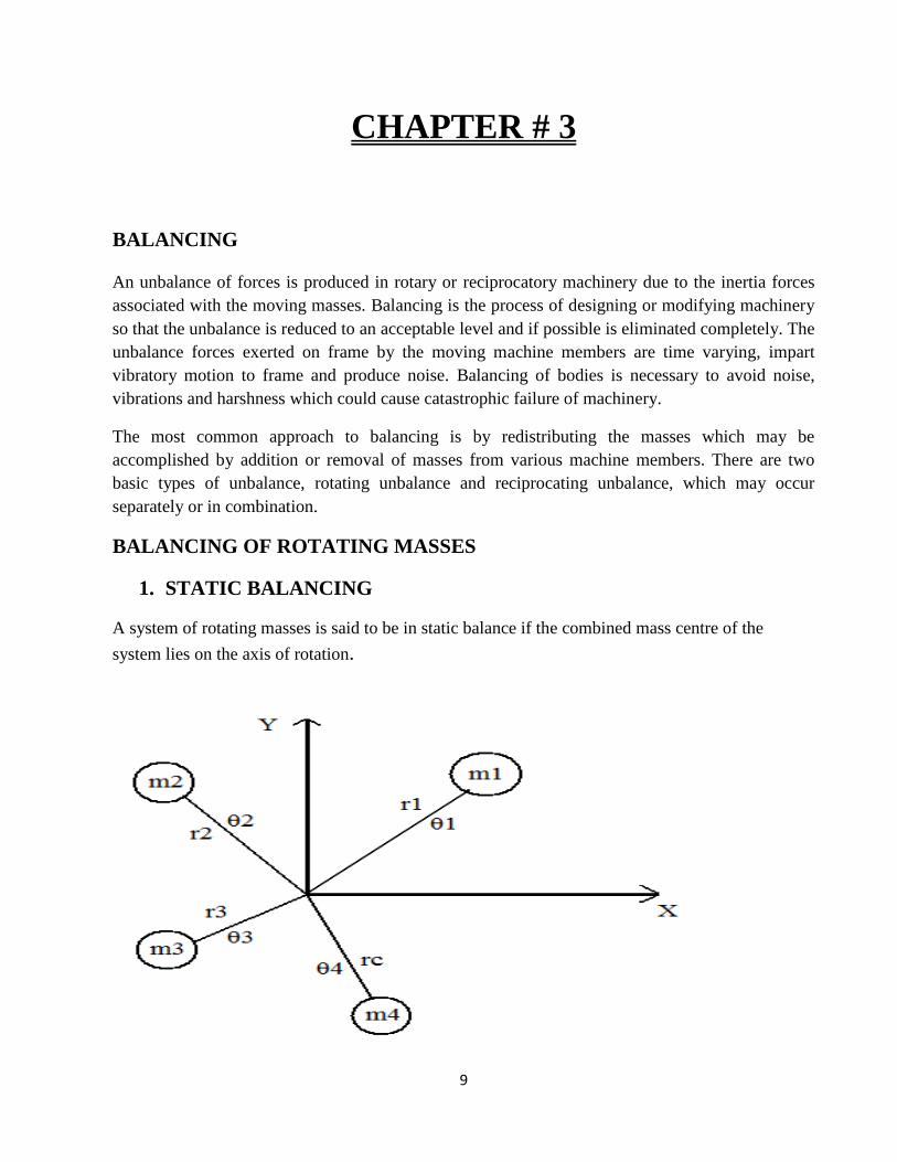
The above figure shows a rigid rotor rotating with a constant angular velocity ω rad/s with four
masses in same transverse plane but at different angular and radial positions.
For static balance,
∑ mrcosθ = m1r1cosθ1 + m2r2cosθ2 + m3r3cosθ3 + m4r4cosθ4 = 0
and ∑ mrsinθ = m1r1sinθ1 + m2r2sinθ2 + m3r3sinθ3 + m4r4sinθ4 = 0
DYNAMIC BALANCING
When several masses rotate in different planes, the centrifugal forces, in addition to being out of
balance , also forms couple .A system of rotating masses is in dynamic balance when there doesn’t
exist any resultant centrifugal force as well as resultant couple.
BALANCING OF RECIPROCATING MASSES
Acceleration of the reciprocating mass of a slider-crank mechanism is given by
Therefore, the forces required to accelerate mass m is,
F= m rω2 [cosθ + (cos2θ)/n]
= m rω2cosθ + m rω
2 (cos2θ)/n
Primary force secondary force
Maximum value of primary force = mrω2
Maximum value of secondary force = mrω2 /n
; n=L/R is much greater than unity; the secondary force is small compared with primary
force and can be safely neglected for slow speed engines.
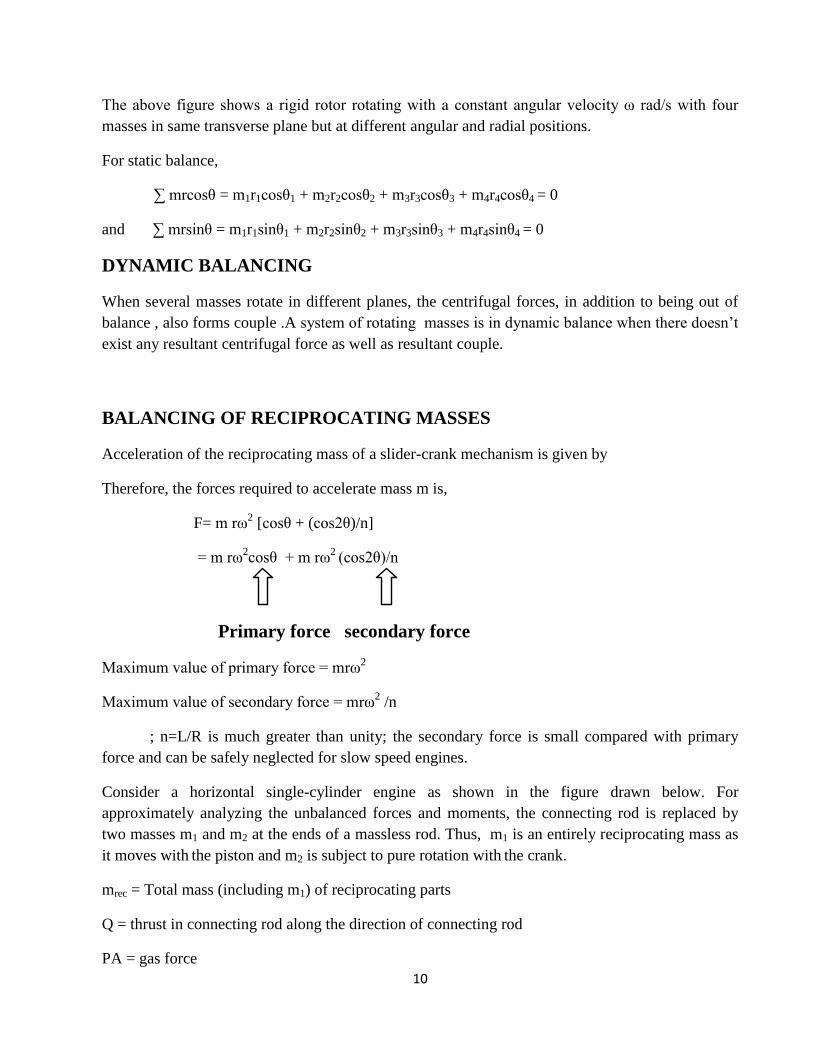
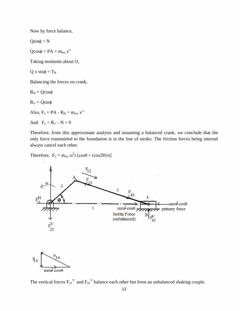
Consider a horizontal single-cylinder engine as shown in the figure drawn below. For
approximately analyzing the unbalanced forces and moments, the connecting rod is replaced by
two masses m1 and m2 at the ends of a massless rod. Thus, m1 is an entirely reciprocating mass as
it moves with the piston and m2 is subject to pure rotation with the crank.
mrec = Total mass (including m1) of reciprocating parts
Q = thrust in connecting rod along the direction of connecting rod
PA = gas force
11
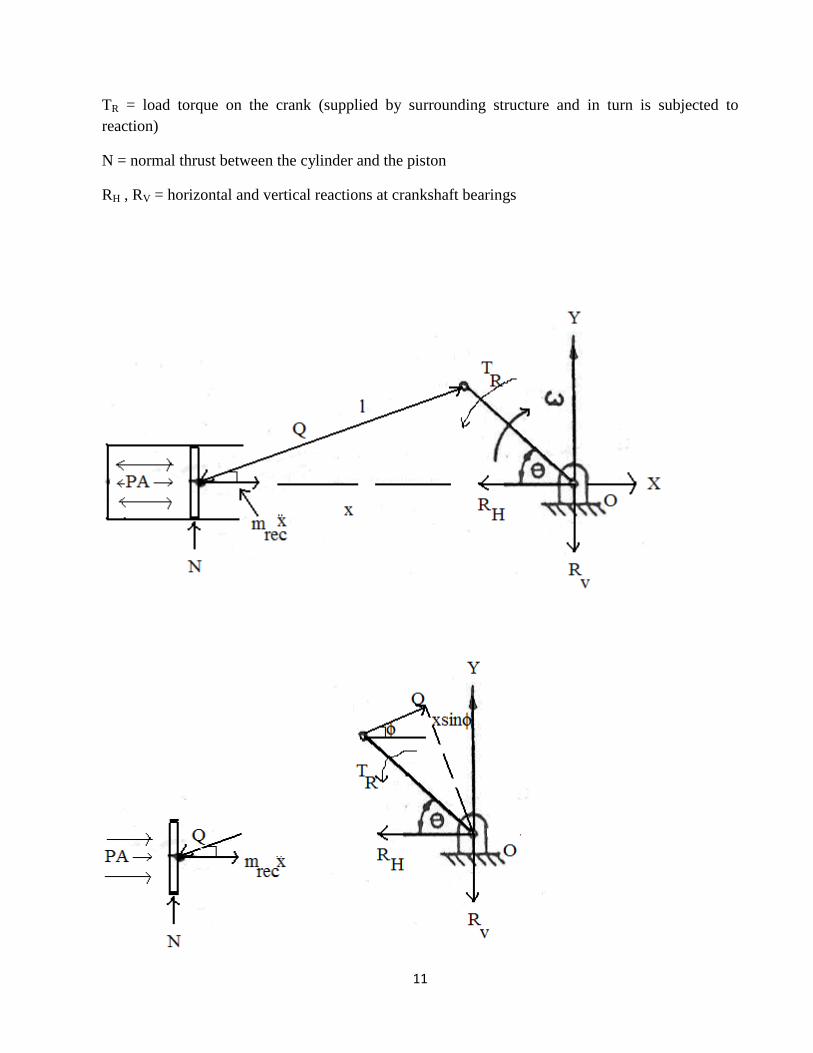
TR = load torque on the crank (supplied by surrounding structure and in turn is subjected to
reaction)
N = normal thrust between the cylinder and the piston
RH , RV = horizontal and vertical reactions at crankshaft bearings
12
Now by force balance,
Qsinϕ = N
Qcosϕ = PA + mrec x”
Taking moments about O,
Q x sinϕ = TR
Balancing the forces on crank,
RH = Qcosϕ
RV = Qsinϕ
Also, Fx = PA - RH = mrec x”
And Fy = Rv – N = 0
Therefore, from this approximate analysis and assuming a balanced crank, we conclude that the
only force transmitted to the foundation is in the line of stroke. The friction forces being internal
always cancel each other.
Therefore, Fx = mrec ω2r [cosθ + (cos2θ)/n]
The vertical forces F21V
and F41V balance each other but form an unbalanced shaking couple.
13
PRIMARY AND SECONDARY BALANCE
Primary balance is the balance attained by compensating for the eccentricities of the rotating
masses, including the connecting rods. Primary balance is controlled by adding or removing mass
to or from the crankshaft, at each end, at the required radius and angle, which varies both due to
design and manufacturing tolerances. Theoretically any conventional engine can be balanced
perfectly for primary balance.
Secondary balance is attained by compensating partially or fully for:
Kinetic energy of the pistons.
Non-sinusoidal motion of the pistons.
Motion of the connecting rods.
Sideways motion of balance shaft weights.
The second of these is the main consideration for secondary balance. There are two main control
mechanisms for secondary balance—matching the phasing of pistons along the crank, so that their
second order contributions cancel, and the use of balance shafts which run at twice engine speed,
and so can provide a balancing force.
No widely used engine configuration is perfectly balanced for secondary excitation. However by
adopting particular definitions for secondary balance, particular configurations can be correctly
claimed to be reasonably balanced in these restricted senses. In particular, the straight six, the flat
six, and the V12 configurations offer exceptional inherent mechanical balance.
14
CHAPTER # 4
THEORETICAL ANALYSIS OF BALANCING OF MULTI-CYLINDER
INLINE ENGINES
Multi-cylinder engines are used in applications where high power is required and it gives an
advantage of better balance of forces and moments. It also provides better and even distribution of
torque to crankshaft and facilitates the smooth running of engine.
The general configurations used are 2-cylinder, 3-cylinder, 4-cylinder, 5-cylinder 6-cylinder and 8-
cylinder inline engines. The 6-cylinder and above configuration engines are completely balanced
for forces and couples. The forces and couples for different cylinder numbers and firing order are
analyzed below theoretically.
FIRING ORDER
In multi-cylinder engines, the crank arrangements are such that there is a smooth distribution of
torque in the engine cycle as well as balance of inertia forces of the reciprocating masses. For
example, in the 4-cylinder engine, a power stroke begins every 180˚ of crank angle in the following
order of cylinder numbers: 1-3-4-2. This order is called firing order.
ENGINE WITH N CYLINDERS INLINE
Angular Positions of cranks on the crankshaft
ϕ1 = 0°
ϕ2 = ϕ2
ϕ3 = ϕ3
: :
ϕn-1 = ϕn-1
ϕn = ϕn
15
SHAKING FORCES
∑ (cosϕ) = (cosϕ1) + cosϕ2 + cosϕ3 +………. + cosϕn-1 + cosϕn
∑ sinϕ = sinϕ1 + sinϕ2 + sinϕ3 +……….+ sinϕn-1 + sinϕn
∑ cos2ϕ = cos2ϕ1 + cos2ϕ2 + cos2ϕ3 +……….cos2ϕn-1 + cos2ϕn
∑ sin2ϕ = sin2ϕ1 + sin2ϕ2 + sin2ϕ3 +………. + sin2ϕn-1 + sin2ϕn
Primary force, FP = mrω2
[cosθ ∑ (cosϕ) - sin θ∑ (sinϕ)]
And,
Secondary force, FS = mrω2/n
[cos2θ ∑ (cos2ϕ) - sin 2θ∑ (sin2ϕ)]
SHAKING COUPLES/MOMENTS
∑ (acosϕ) = 0*(cosϕ1) + a*(cosϕ2) + 2a*(cosϕ3) +………. + (n-2)a*(cosϕn-1) + (n-1)*(cosϕn)
∑ (asinϕ) = 0*(sinϕ1) + a*(sinϕ2) + 2a*(sinϕ3) +………. + (n-2) a*(sinϕn-1) + (n-1)*(sinϕn)
∑ (acos2ϕ) = 0*(cos2ϕ1) + a*(cos2ϕ2) + 2a*(cos2ϕ3) +………. + (n-2)a*(cos2ϕn-1) + (n-1)*(cos2ϕn)
∑ (asin2ϕ) = 0*(sin2ϕ1) + a*(sin2ϕ2) + 2a*(sin2ϕ3) +………. + (n-2) a*(sin2ϕn-1) + (n-1)*(sin2ϕn)
Primary moment, MP = mrω2 [cosθ ∑ (acosϕ) - sin θ∑ (asinϕ)]
And,
Secondary moment, MS = mrω2/n
[cos2θ ∑ (acos2ϕ) - sin 2θ∑ (asin2ϕ)
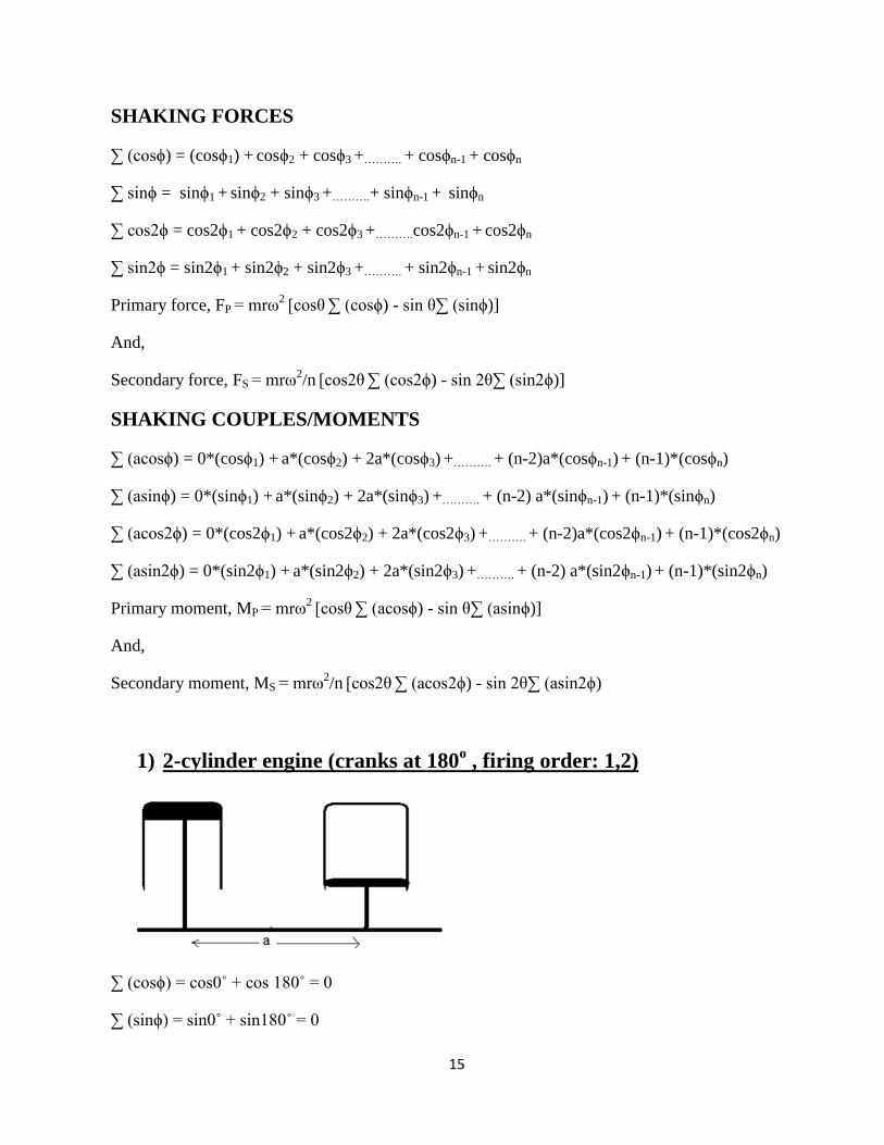
1) 2-cylinder engine (cranks at 180o , firing order: 1,2)
∑ (cosϕ) = cos0˚ + cos 180˚ = 0
∑ (sinϕ) = sin0˚ + sin180˚ = 0
16
∑ (cos2ϕ) = cos0˚ + cos 360˚ = 2
∑ (sin2ϕ) = sin0˚ + sin360˚ = 0
SHAKING FORCES
FP = mrω2
[cosθ ∑ (cosϕ) - sin θ∑ (sinϕ)] = 0
FSL = mrω2/n
[cos2θ ∑ (cos2ϕ) - sin 2θ∑ (sin2ϕ)] = 2mrω
2/n
(cos2θ)
∑ (acosϕ) = -a
∑ (asinϕ) = 0
∑ (acos2ϕ) = a
∑ (asin2ϕ) = 0
SHAKING MOMENTS
MP = mrω2 [cosθ ∑ (acosϕ) - sin θ∑ (asinϕ)] = - mrω
2acos θ
MS = mrω2/n
[cos2θ ∑ (acos2ϕ) - sin 2θ∑ (asin2ϕ)] = mrω
2a/n (cos2θ)
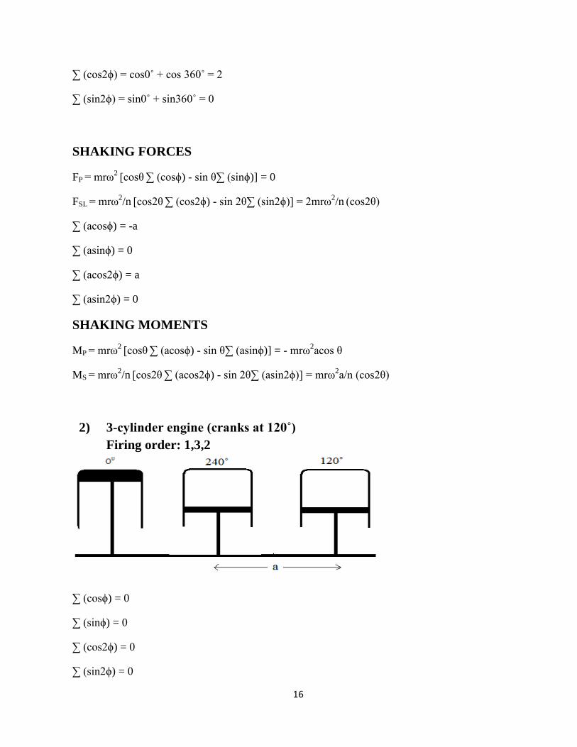
2) 3-cylinder engine (cranks at 120˚)
Firing order: 1,3,2
∑ (cosϕ) = 0
∑ (sinϕ) = 0
∑ (cos2ϕ) = 0
∑ (sin2ϕ) = 0

17
SHAKING FORCES
FP = 0
FS= 0
∑ (acosϕ) = -1.5a
∑ (asinϕ) = 0.866a
∑ (acos2ϕ) = -1.5a
∑ (asin2ϕ) = -0.866a
SHAKING MOMENTS
MP = -mrω2a[1.5cos θ + 0.866sin θ]
MS = mrω2a/n [-1.5cos2θ + 0.866sin2θ]
3) 4-cylinder engine(cranks at 180˚)
a) Firing order: 1432
∑ (cosϕ) = 0
∑ (sinϕ) = 0
∑ (cos2ϕ) = 4
∑ (sin2ϕ) = 0
SHAKING FORCES
FP = 0
18
FS= 4mrω2/n
[cos2θ]
FS(max) = 4mrω2/n
∑ (acosϕ) = -2a
∑ (asinϕ) = 0
∑ (acos2ϕ) = 6a
∑ (asin2ϕ) = 0
SHAKING MOMENTS
MP= -2mr ω2acosθ
Mp (max) = 2mrω2 a
Ms= 6mrω2a/n
[cos2θ]
MS (max) = 6mrω2 a/n
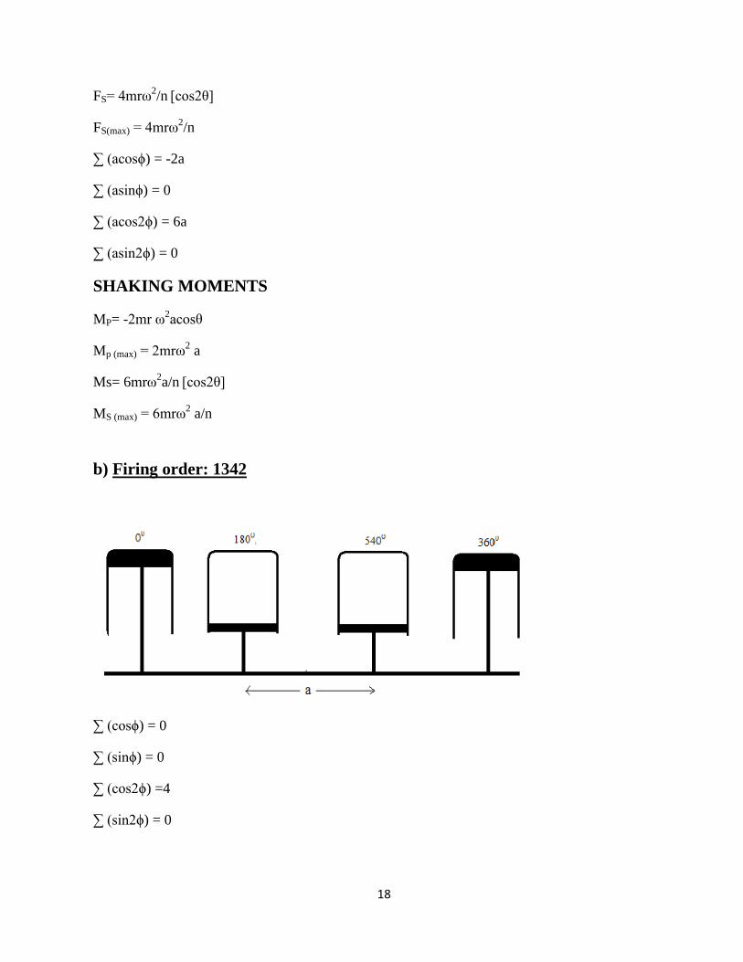
b) Firing order: 1342
∑ (cosϕ) = 0
∑ (sinϕ) = 0
∑ (cos2ϕ) =4
∑ (sin2ϕ) = 0
19
SHAKING FORCES
FP = 0
FS= 4mrω2/n
[cos2θ]
FS(max) = 4mrω2/n
∑ (acosϕ) = 0
∑ (asinϕ) = 0
∑ (acos2ϕ) = 6a
∑ (asin2ϕ) = 0
SHAKING MOMENTS
MP= 0
Ms= 6mrω2a/n
[cos2θ]
M S(max) = 6mrω2a/n
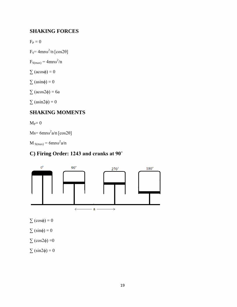
C) Firing Order: 1243 and cranks at 90˚
∑ (cosϕ) = 0
∑ (sinϕ) = 0
∑ (cos2ϕ) =0
∑ (sin2ϕ) = 0
20
SHAKING FORCE
FP = 0
FS= 0
∑ (acosϕ) = -3a
∑ (asinϕ) = -a
∑ (acos2ϕ) = 0
∑ (asin2ϕ) = 0
SHAKING MOMENTS
MP= mrω2a [-3cos θ1 + sin θ1]
Ms= 0
The above theoretical analysis can also be done for various engines with increasing number of
cylinders like 5-cylinder, 6-cylinder and so on. But calculations will be much more, so we will now
go for computer-aided analysis of balancing of multi-cylinder inline engines. A program has been
developed in C++ for the required analysis. The program will evaluate all forces and couples acting
on the engine for different number of cylinders and different firing orders.
C++ PROGRAM FOR DYNAMIC ANALYSIS OF MULTI-CYLINDER
INLINE ENGINES
#include<iostream.h>
#include<stdio.h>
#include<conio.h>
#include<math.h>
#define N 6
void main()
{
21
int phi [N];
int seq [N];
float m,r,w,n,a,theta;
cout<<"Mention the firing order :\n";
for(int i=0;i<N;i++)
{
cin>>seq[i];
}
cout<<"enter mass :\n";
cin>>m;
cout<<"enter crank radius :\n";
cin>>r;
cout<<"enter angular velocity :\n";
cin>>w;
cout<<"enter n :\n";
cin>>n;
cout<<"enter cylinder pitch :\n";
cin>>a;
cout<<"enter theta :\n";
cin>>theta;
theta = (theta*M_PI)/180;
int delta;
cout<<"enter the crank angle diff. :\n";
cin>>delta;
22
phi[seq[0]-1]=0;//initial cylinder angle taken 0
for(i=1;i<N;i++)
{
phi[seq[i]-1]=i*delta;
}
for(i=0;i<N;i++)
{
cout<<"angle for cylinder "<<seq[i]<<" :"<<phi[seq[i]-1]<<"\n";
}
float sigmacos=0,sigmasin=0,sigma2cos=0,sigma2sin=0;
for(i=0;i<N;i++)
{
sigmacos = sigmacos + cos((phi[i]*M_PI)/180);
sigmasin = sigmasin + sin((phi[i]*M_PI)/180);
sigma2cos = sigma2cos + cos((2*phi[i]*M_PI)/180);
sigma2sin = sigma2sin + sin((2*phi[i]*M_PI)/180);
}
float fp=0;
fp = m*r*w*w*((cos(theta)*sigmacos)-(sin(theta)*sigmasin));
cout<<"\nThe primary force is :"<<fp<<"\n";
float fs = (m*r*w*w*((cos(2*theta)*sigma2cos)-(sin(2*theta)*sigma2sin)))/n;
cout<<"The secondary force is :"<<fp<<"\n\n";
float asigmacos=0,asigmasin=0,asigma2cos=0,asigma2sin=0;
for(i=0;i<N;i++)
{
23
asigmacos = asigmacos + a*i*cos((phi[i]*M_PI)/180);
asigmasin = asigmasin + a*i*sin((phi[i]*M_PI)/180);
asigma2cos = asigma2cos + a*i*cos((2*phi[i]*M_PI)/180);
asigma2sin = asigma2sin + a*i*sin((2*phi[i]*M_PI)/180);
}
float mp=0,ms=0;
mp = m*r*w*w*((cos(theta1)*asigmacos)-(sin(theta1)*asigmasin));
ms = (m*r*w*w*((cos(2*theta)*asigma2cos)-(sin(2*theta)*asigma2sin)))/n;
cout<<"The primary moment is :"<<mp<<"\n";
cout<<"The secondary moment is :"<<ms<<"\n\n";
getch();
}
24
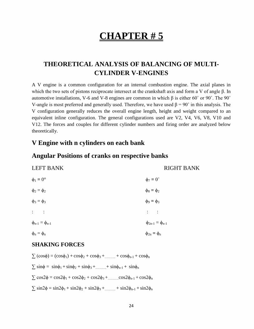
CHAPTER # 5
THEORETICAL ANALYSIS OF BALANCING OF MULTI-
CYLINDER V-ENGINES
A V engine is a common configuration for an internal combustion engine. The axial planes in
which the two sets of pistons reciprocate intersect at the crankshaft axis and form a V of angle β. In
automotive installations, V-6 and V-8 engines are common in which β is either 60˚ or 90˚. The 90˚
V-angle is most preferred and generally used. Therefore, we have used β = 90˚ in this analysis. The
V configuration generally reduces the overall engine length, height and weight compared to an
equivalent inline configuration. The general configurations used are V2, V4, V6, V8, V10 and
V12. The forces and couples for different cylinder numbers and firing order are analyzed below
theoretically.
V Engine with n cylinders on each bank
Angular Positions of cranks on respective banks
LEFT BANK RIGHT BANK
ϕ1 = 0° ϕ7 = 0˚
ϕ2 = ϕ2 ϕ8 = ϕ2
ϕ3 = ϕ3 ϕ9 = ϕ3
: : : :
ϕn-1 = ϕn-1 ϕ2n-1 = ϕn-1
ϕn = ϕn ϕ2n = ϕn
SHAKING FORCES
∑ (cosϕ) = (cosϕ1) + cosϕ2 + cosϕ3 +………. + cosϕn-1 + cosϕn
∑ sinϕ = sinϕ1 + sinϕ2 + sinϕ3 +……….+ sinϕn-1 + sinϕn
∑ cos2ϕ = cos2ϕ1 + cos2ϕ2 + cos2ϕ3 +……….cos2ϕn-1 + cos2ϕn
∑ sin2ϕ = sin2ϕ1 + sin2ϕ2 + sin2ϕ3 +………. + sin2ϕn-1 + sin2ϕn
25
Since the two banks are identical, therefore the dynamic conditions of both are same except the
crank angles θ1 and θ2 which are related to each other aS θ2= θ1-90°, where θ1 is the angle which 1st
crank of left bank makes with the axial plane of left bank and θ2 is the angle which 1st crank of
right bank makes with the axial plane of left bank. Hence we can analyse one bank and result can
be similarly obtained for the other.
Primary force for left bank = FPL
Primary force for right bank = FPR
Secondary force for left bank = FSL
Secondary force for right bank = FSR
FPL = mrω2
[cosθ1 ∑ (cosϕ) - sin θ1∑ (sinϕ)]
FPR = mrω2
[cosθ2 ∑ (cosϕ) - sin θ2∑ (sinϕ)]
The resultant primary force FP is given by:
FP = [FPL2 + FPR
2]
1/2
The angle μ which FP makes with the axial plane of left bank is given by:
tanμ = FPR/ FPL
Similarly,
FSL = mrω2/n
[cos2θ1 ∑ (cos2ϕ) - sin 2θ1∑ (sin2ϕ)]
FSR = mrω2/n
[cos2θ2 ∑ (cos2ϕ) - sin 2θ2∑ (sin2ϕ)]
The resultant secondary force Fs is given by:
FS = [FSL2 + FSR
2]
1/2
The angle λ which FS makes with the axial plane of left bank is given by:
tan λ = FSR/ FSL
SHAKING COUPLES/MOMENTS
∑ (acosϕ) = 0*(cosϕ1) + a*(cosϕ2) + 2a*(cosϕ3) +………. + (n-2)a*(cosϕn-1) + (n-1)*(cosϕn)
∑ (asinϕ) = 0*(sinϕ1) + a*(sinϕ2) + 2a*(sinϕ3) +………. + (n-2) a*(sinϕn-1) + (n-1)*(sinϕn)
∑ (acos2ϕ) = 0*(cos2ϕ1) + a*(cos2ϕ2) + 2a*(cos2ϕ3) +………. + (n-2)a*(cos2ϕn-1) + (n-1)*(cos2ϕn)
∑ (asin2ϕ) = 0*(sin2ϕ1) + a*(sin2ϕ2) + 2a*(sin2ϕ3) +………. + (n-2) a*(sin2ϕn-1) + (n-1)*(sin2ϕn)
26
Primary moment for left bank = MPL
Primary moment for right bank = MPR
Secondary moment for left bank = MSL
Secondary moment for right bank = MSR
MPL = mrω2
[cosθ1 ∑ (acosϕ) - sin θ1∑ (asinϕ)]
MPR = mrω2 [cosθ2 ∑ (acosϕ) - sin θ2∑ (asinϕ)]
The resultant Primary Moment MP is given by:
MP = [MPL2 + MPR
2]
1/2
The angle which MP makes with the axial plane of left bank is given by:
tan = MPR/ MPL
Similarly,
MSL = mrω2/n
[cos2θ1 ∑ (acos2ϕ) - sin 2θ1∑ (asin2ϕ)]
MSR = mrω2/n
[cos2θ2 ∑ (acos2ϕ) - sin 2θ2∑ (asin2ϕ)]
The resultant Secondary Moment MS is given by:
MS = [MSL2 + MSR
2]
1/2
The angle which MS makes with the axial plane of left bank is given by:
tan = MSR/ MSL
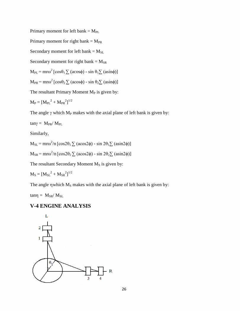
V-4 ENGINE ANALYSIS

27
LEFT BANK RIGHT BANK
ϕ1 = 0° ϕ3 = 0˚
ϕ2 = 180° ϕ4 = 180°
SHAKING FORCES
∑ cosϕ = cos0° + cos180° = 0
∑ sinϕ = sin0° + sin180° = 0
∑ cos2ϕ = cos0° + cos360° = 2
∑ sin2ϕ = sin0° + sin360° = 0
Therefore,
FPL = mrω2
[cosθ1 ∑ (cosϕ) - sin θ1∑ (sinϕ)] = 0
FPR = mrω2
[cosθ2 ∑ (cosϕ) - sin θ2∑ (sinϕ)] = 0
FSL = mrω2/n
[cos2θ1 ∑ (cos2ϕ) - sin 2θ1∑ (sin2ϕ)] = 2mrω
2/n
(cos2θ1)
FSR = mrω2/n
[cos2θ2 ∑ (cos2ϕ) - sin 2θ2∑ (sin2ϕ)] = 2mrω
2/n
(cos2θ2)
= -2mrω2/n
(cos2θ1)
Resultant secondary force, FS = [FSL2 + FSR
2]1/2
=22 mrω2/n
tanλ = FSR/ FSL = tan2
λ = 21
Hence the resultant secondary force has a constant magnitude but the direction varies twice as that
of crank.
SHAKING COUPLES/MOMENTS
∑ (acosϕ) = -a
∑ (asinϕ) = 0
∑ (acos2ϕ) = a
∑ (asin2ϕ) = 0
28
MPL = mrω2
[cosθ1 ∑ (acosϕ) - sin θ1∑ (asinϕ)] = - mrω2acos θ1
MPR = mrω2 [cosθ2 ∑ (acosϕ) - sin θ2∑ (asinϕ)] = -mrω
2asin θ1
MP = [MPL2 + MPR
2]
1/2 = mrω
2a
tan = MPR/ MPL = tanθ1
= 1
Similarly,
MSL = mrω2/n
[cos2θ1 ∑ (acos2ϕ) - sin 2θ1∑ (asin2ϕ)] = mrω
2a/n (cos2θ1)
MSR = mrω2/n
[cos2θ2 ∑ (acos2ϕ) - sin 2θ2∑ (asin2ϕ)] = mrω
2a/n (cos2θ2) = -mrω
2a/n (cos2θ1)
MS = [MSL2 + MSR
2]
1/2 = 2 mrω
2a/n (cos2θ1)
tan = MSR/ MSL = -1
= 315°
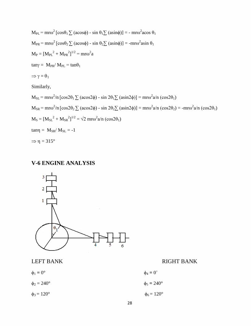
V-6 ENGINE ANALYSIS
LEFT BANK RIGHT BANK
ϕ1 = 0° ϕ4 = 0˚
ϕ2 = 240° ϕ5 = 240°
ϕ3 = 120° ϕ6 = 120°
29
SHAKING FORCES
∑ cosϕ = cos0° + cos240° + cos120° = 0
∑ sinϕ = sin0° + sin240° + sin120°= 0
∑ cos2ϕ = cos0° + cos480° + cos240° = 0
∑ sin2ϕ = sin0° + sin480° + sin240°= 0
Therefore,
FPL = mrω2
[cosθ1 ∑ (cosϕ) - sin θ1∑ (sinϕ)] = 0
FPR = mrω2
[cosθ2 ∑ (cosϕ) - sin θ2∑ (sinϕ)] = 0
FSL = mrω2/n
[cos2θ1 ∑ (cos2ϕ) - sin 2θ1∑ (sin2ϕ)] = 0
FSR = mrω2/n
[cos2θ2 ∑ (cos2ϕ) - sin 2θ2∑ (sin2ϕ)] = 0
SHAKING COUPLES/MOMENTS
∑ (acosϕ) = -1.5a
∑ (asinϕ) = 0.866a
∑ (acos2ϕ) = -1.5a
∑ (asin2ϕ) = -0.866a
MPL = mrω2
[cosθ1 ∑ (acosϕ) - sin θ1∑ (asinϕ)] = - mrω2a [1.5cos θ1 + 0.866sin θ1]
MPR = mrω2 [cosθ2 ∑ (acosϕ) - sin θ2∑ (asinϕ)] = mrω
2a [1.5sin θ1 - 0.866cos θ1]
MP = [MPL2 + MPR
2]
1/2
tan = MPR/ MPL
Similarly,
MSL = mrω2/n
[cos2θ1 ∑ (acos2ϕ) - sin 2θ1∑ (asin2ϕ)] = mrω
2a/n [-1.5cos θ1 + 0.866sin θ1]
MSR = mrω2/n
[cos2θ2 ∑ (acos2ϕ) - sin 2θ2∑ (asin2ϕ)] = mrω
2a/n [1.5cos θ1 - 0.866sin θ1]
MS = [MSL2 + MSR
2]
1/2
tan = MSR/ MSL
30
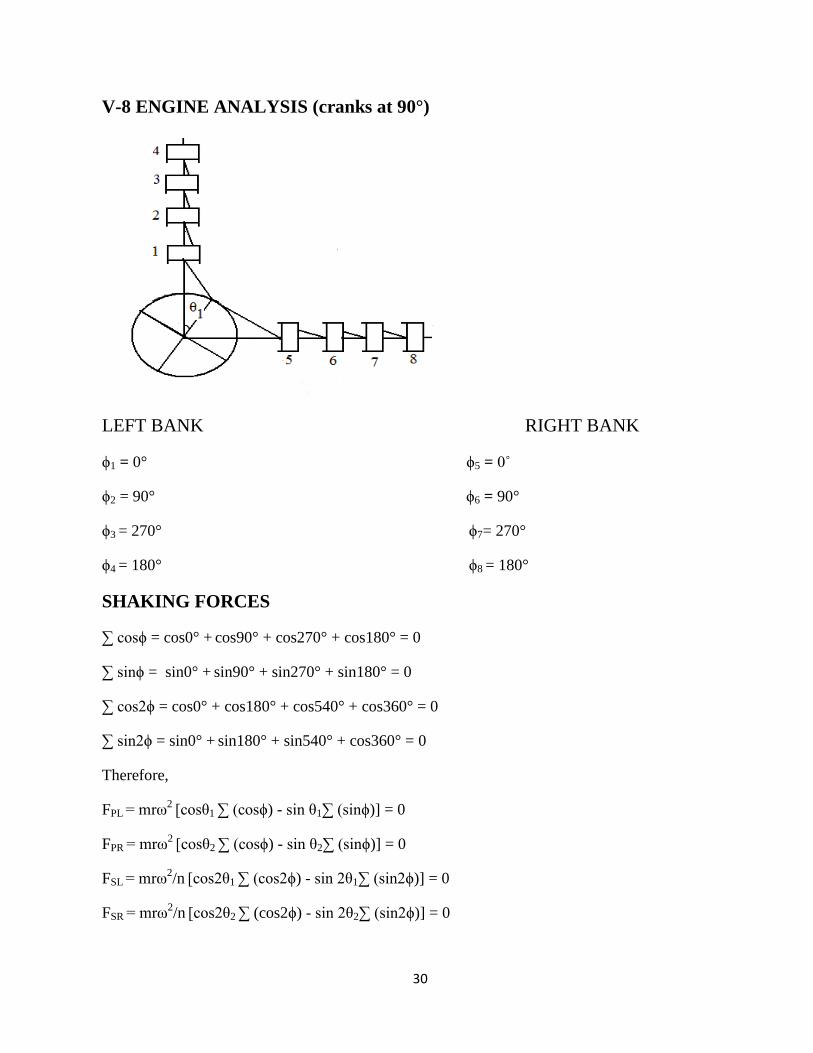
V-8 ENGINE ANALYSIS (cranks at 90°)
LEFT BANK RIGHT BANK
ϕ1 = 0° ϕ5 = 0˚
ϕ2 = 90° ϕ6 = 90°
ϕ3 = 270° ϕ7= 270°
ϕ4 = 180° ϕ8 = 180°
SHAKING FORCES
∑ cosϕ = cos0° + cos90° + cos270° + cos180° = 0
∑ sinϕ = sin0° + sin90° + sin270° + sin180° = 0
∑ cos2ϕ = cos0° + cos180° + cos540° + cos360° = 0
∑ sin2ϕ = sin0° + sin180° + sin540° + cos360° = 0
Therefore,
FPL = mrω2
[cosθ1 ∑ (cosϕ) - sin θ1∑ (sinϕ)] = 0
FPR = mrω2
[cosθ2 ∑ (cosϕ) - sin θ2∑ (sinϕ)] = 0
FSL = mrω2/n
[cos2θ1 ∑ (cos2ϕ) - sin 2θ1∑ (sin2ϕ)] = 0
FSR = mrω2/n
[cos2θ2 ∑ (cos2ϕ) - sin 2θ2∑ (sin2ϕ)] = 0
31
SHAKING COUPLES/MOMENTS
∑ (acosϕ) = -3a
∑ (asinϕ) = -a
∑ (acos2ϕ) = 0
∑ (asin2ϕ) = 0
MPL = mrω2
[cosθ1 ∑ (acosϕ) - sin θ1∑ (asinϕ)] = mrω2a[-3cos θ1 + sin θ1]
MPR = mrω2 [cosθ2 ∑ (acosϕ) - sin θ2∑ (asinϕ)] = mrω
2a [-3sin θ1 - cos θ1]
MP = [MPL2 + MPR
2]
1/2
tan = MPR/ MPL
Similarly,
MSL = mrω2/n
[cos2θ1 ∑ (acos2ϕ) - sin 2θ1∑ (asin2ϕ)] = 0
MSR = mrω2/n
[cos2θ2 ∑ (acos2ϕ) - sin 2θ2∑ (asin2ϕ)] = 0
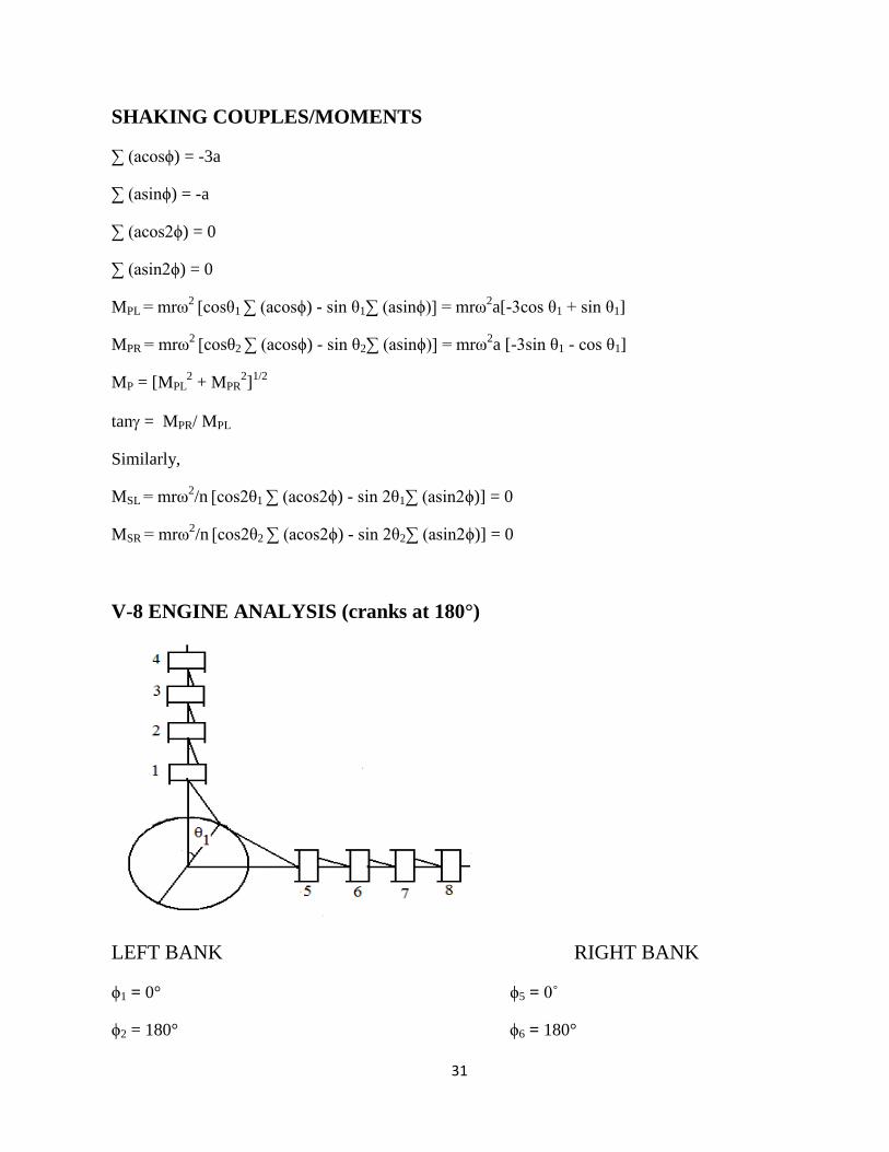
V-8 ENGINE ANALYSIS (cranks at 180°)
LEFT BANK RIGHT BANK
ϕ1 = 0° ϕ5 = 0˚
ϕ2 = 180° ϕ6 = 180°
32
ϕ3 = 180° ϕ7= 180°
ϕ4 = 0° ϕ8 = 0°
SHAKING FORCES
∑ cosϕ = cos0° + cos180° + cos180° + cos0° = 0
∑ sinϕ = sin0° + sin180° + sin180° + sin0° = 0
∑ cos2ϕ = cos0° + cos360° + cos360° + cos0° = 4
∑ sin2ϕ = sin0° + sin360° + sin360° + sin0° = 0
Therefore,
FPL = mrω2
[cosθ1 ∑ (cosϕ) - sin θ1∑ (sinϕ)] = 0
FPR = mrω2
[cosθ2 ∑ (cosϕ) - sin θ2∑ (sinϕ)] = 0
FSL = mrω2/n
[cos2θ1 ∑ (cos2ϕ) - sin 2θ1∑ (sin2ϕ)] = 4mrω
2/n
[cos2θ1]
FSR = mrω2/n
[cos2θ2 ∑ (cos2ϕ) - sin 2θ2∑ (sin2ϕ)] = -4mrω
2/n
[cos2θ1]
FS = 42mrω2/n (cos2θ1)
SHAKING COUPLES/MOMENTS
∑ (acosϕ) = 0
∑ (asinϕ) = 0
∑ (acos2ϕ) = 6a
∑ (asin2ϕ) = 0
MPL = mrω2
[cosθ1 ∑ (acosϕ) - sin θ1∑ (asinϕ)] = 0
MPR = mrω2 [cosθ2 ∑ (acosϕ) - sin θ2∑ (asinϕ)] = 0
And,
MSL = mrω2/n
[cos2θ1 ∑ (acos2ϕ) - sin 2θ1∑ (asin2ϕ)] = 6mrω
2a/n
(cos2θ1)
MSR = mrω2/n
[cos2θ2 ∑ (acos2ϕ) - sin 2θ2∑ (asin2ϕ)] = - 6mrω
2a/n
(cos2θ1)
MS = 62mrω2a/n
(cos2θ1)
33
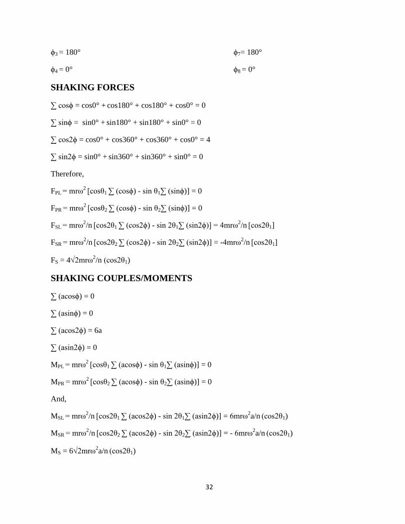
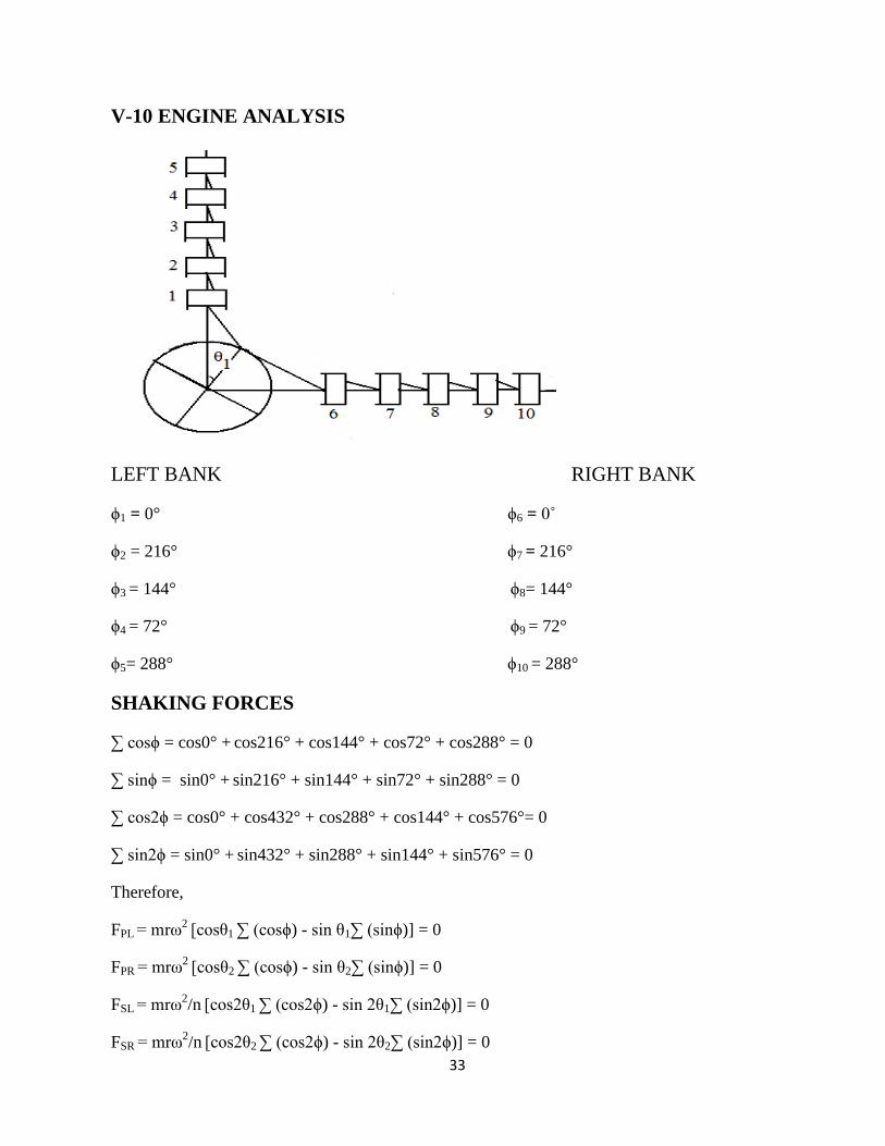
V-10 ENGINE ANALYSIS
LEFT BANK RIGHT BANK
ϕ1 = 0° ϕ6 = 0˚
ϕ2 = 216° ϕ7 = 216°
ϕ3 = 144° ϕ8= 144°
ϕ4 = 72° ϕ9 = 72°
ϕ5= 288° ϕ10 = 288°
SHAKING FORCES
∑ cosϕ = cos0° + cos216° + cos144° + cos72° + cos288° = 0
∑ sinϕ = sin0° + sin216° + sin144° + sin72° + sin288° = 0
∑ cos2ϕ = cos0° + cos432° + cos288° + cos144° + cos576°= 0
∑ sin2ϕ = sin0° + sin432° + sin288° + sin144° + sin576° = 0
Therefore,
FPL = mrω2
[cosθ1 ∑ (cosϕ) - sin θ1∑ (sinϕ)] = 0
FPR = mrω2
[cosθ2 ∑ (cosϕ) - sin θ2∑ (sinϕ)] = 0
FSL = mrω2/n
[cos2θ1 ∑ (cos2ϕ) - sin 2θ1∑ (sin2ϕ)] = 0
FSR = mrω2/n
[cos2θ2 ∑ (cos2ϕ) - sin 2θ2∑ (sin2ϕ)] = 0
34
SHAKING COUPLES/MOMENTS
∑ (acosϕ) = -0.264a
∑ (asinϕ) = -0.3633a
∑ (acos2ϕ) = -4.736a
∑ (asin2ϕ) = -1.5389a
MPL = mrω2
[cosθ1 ∑ (acosϕ) - sin θ1∑ (asinϕ)] = mrω2a [-0.264cos θ1 + 0.3633sin θ1]
MPR = mrω2 [cosθ2 ∑ (acosϕ) - sin θ2∑ (asinϕ)] = mrω
2a [-0.264sin θ1 – 0.3633cos θ1]
MP = [MPL2 + MPR
2]
1/2
tan = MPR/ MPL
Similarly,
MSL = mrω2/n
[cos2θ1 ∑ (acos2ϕ) - sin 2θ1∑ (asin2ϕ)] = mrω
2a/n [-4.736cos2θ1 + 1.5389sin2 θ1]
MSR = mrω2/n
[cos2θ2 ∑ (acos2ϕ) - sin 2θ2∑ (asin2ϕ)] = mrω
2a/n [4.736cos2θ1 - 1.5389sin2 θ1]
MS = [MSL2 + MSR
2]
1/2
tan = MSR/ MSL
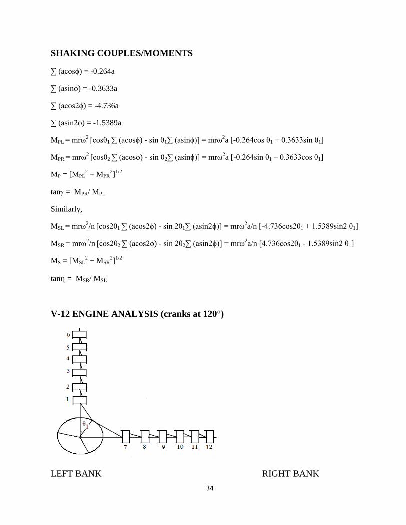
V-12 ENGINE ANALYSIS (cranks at 120°)
LEFT BANK RIGHT BANK
35
ϕ1 = 0° ϕ7 = 0˚
ϕ2 = 240° ϕ8 = 240°
ϕ3 = 120° ϕ9= 120°
ϕ4 = 120° ϕ10 = 120°
ϕ5= 240° ϕ11 = 240°
ϕ6= 0° ϕ12= 0°
SHAKING FORCES
∑ cosϕ = cos0˚ + cos240˚ + cos120˚ + cos120˚ + cos240˚ + cos0˚ = 0
∑ sinϕ = sin0˚ + sin240˚ + sin120˚ + sin120˚ + sin240˚ + sin0˚ = 0
∑ cos2ϕ = cos0˚ + cos480˚ + cos240˚ + cos240˚ + cos480˚ + cos0˚ = 0
∑ sin2ϕ = sin0˚ + sin480˚ + sin240˚ + sin240˚ + sin480˚ + sin0˚ = 0
Therefore,
FPL = mrω2
[cosθ1 ∑ (cosϕ) - sin θ1∑ (sinϕ)] = 0
FPR = mrω2
[cosθ2 ∑ (cosϕ) - sin θ2∑ (sinϕ)] = 0
FSL = mrω2/n
[cos2θ1 ∑ (cos2ϕ) - sin 2θ1∑ (sin2ϕ)] = 0
FSR = mrω2/n
[cos2θ2 ∑ (cos2ϕ) - sin 2θ2∑ (sin2ϕ)] = 0
SHAKING COUPLES/MOMENTS
∑ (acosϕ) = 0
∑ (asinϕ) = 0
∑ (acos2ϕ) = 0
∑ (asin2ϕ) = 0
MPL = mrω2
[cosθ1 ∑ (acosϕ) - sin θ1∑ (asinϕ)] = 0
MPR = mrω2 [cosθ2 ∑ (acosϕ) - sin θ2∑ (asinϕ)] = 0
MP = [MPL2 + MPR
2]
1/2 = 0
36
Similarly,
MSL = mrω2/n
[cos2θ1 ∑ (acos2ϕ) - sin 2θ1∑ (asin2ϕ)] = 0
MSR = mrω2/n
[cos2θ2 ∑ (acos2ϕ) - sin 2θ2∑ (asin2ϕ)] = 0
MS = [MSL2 + MSR
2]
1/2 = 0
Therefore, it is a completely balanced engine with no shaking forces and couples.
The above theoretical analysis can also be done for various engines with increasing number of
cylinders like V-14, V-16 and so on. But calculations will be much more, so we will go for
computer-aided analysis of balancing of multi-cylinder V engines. A program has been developed in
C++ for the required analysis. The program will evaluate all forces and couples acting on the engine
for different number of cylinders and different firing orders.
C++ PROGRAM FOR DYNAMIC ANALYSIS OF MULTI-CYLINDER
V-ENGINES
#include<iostream.h>
#include<stdio.h>
#include<conio.h>
#include<math.h>
#define N 6
void main()
{
int phi [N];
int seq [N];
float m,r,w,n,a,theta1,theta2;
cout<<"Mention the firing order :\n";
for(int i=0;i<N;i++)
{
37
cin>>seq[i];
}
cout<<"enter mass :\n";
cin>>m;
cout<<"enter crank radius :\n";
cin>>r;
cout<<"enter angular velocity :\n";
cin>>w;
cout<<"enter n :\n";
cin>>n;
cout<<"enter cylinder pitch :\n";
cin>>a;
cout<<"enter theta1 :\n";
cin>>theta1;
theta1 = (theta1*M_PI)/180;
theta2 = ((theta1 - 90)*M_PI/180) ;
int delta;
cout<<"enter the crank angle diff. :\n";
cin>>delta;
phi[seq[0]-1]=0;//initial cylinder angle taken 0
for(i=1;i<N;i++)
{
phi[seq[i]-1]=i*delta;
}
38
for(i=0;i<N;i++)
{
cout<<"angle for cylinder "<<seq[i]<<" :"<<phi[seq[i]-1]<<"\n";
}
float sigmacos=0,sigmasin=0,sigma2cos=0,sigma2sin=0;
for(i=0;i<N;i++)
{
sigmacos = sigmacos + cos((phi[i]*M_PI)/180);
sigmasin = sigmasin + sin((phi[i]*M_PI)/180);
sigma2cos = sigma2cos + cos((2*phi[i]*M_PI)/180);
sigma2sin = sigma2sin + sin((2*phi[i]*M_PI)/180);
}
float forcepl=0,forcepr=0;
forcepl = m*r*w*w*((cos(theta1)*sigmacos)-(sin(theta1)*sigmasin));
forcepr = m*r*w*w*((cos(theta2)*sigmacos)-(sin(theta2)*sigmasin));
cout<<"\nprimary forces :"<<forcepl<<" "<<forcepr<<"\n";
float forcesl = (m*r*w*w*((cos(2*theta1)*sigma2cos)-(sin(2*theta1)*sigma2sin)))/n;
float forcesr = (m*r*w*w*((cos(2*theta2)*sigma2cos)-(sin(2*theta2)*sigma2sin)))/n;
cout<<"secondary forces :"<<forcesl<<" "<<forcesr<<"\n\n";
float asigmacos=0,asigmasin=0,asigma2cos=0,asigma2sin=0;
for(i=0;i<N;i++)
{
asigmacos = asigmacos + a*i*cos((phi[i]*M_PI)/180);
asigmasin = asigmasin + a*i*sin((phi[i]*M_PI)/180);
asigma2cos = asigma2cos + a*i*cos((2*phi[i]*M_PI)/180);
39
asigma2sin = asigma2sin + a*i*sin((2*phi[i]*M_PI)/180);
}
float mpl=0,mpr=0,msl=0,msr=0;
mpl = m*r*w*w*((cos(theta1)*asigmacos)-(sin(theta1)*asigmasin));
mpr = m*r*w*w*((cos(theta2)*asigmacos)-(sin(theta2)*asigmasin));
msl = (m*r*w*w*((cos(2*theta1)*asigma2cos)-(sin(2*theta1)*asigma2sin)))/n;
msr = (m*r*w*w*((cos(2*theta2)*sigma2cos)-(sin(2*theta2)*sigma2sin)))/n;
cout<<"primary moment values :"<<mpl<<" "<<mpr<<"\n";
cout<<"secondary moment values :"<<msl<<" "<<msr<<"\n\n";
float fp,fs,mp,ms,thetafp,thetafs,thetamp,thetams;
fp = sqrt(forcepl*forcepl + forcepr*forcepr);
fs = sqrt(forcesl*forcesl + forcesr*forcesr);
mp = sqrt(mpl*mpl + mpr*mpr);
ms = sqrt(msl*msl + msr*msr);
thetafp = atan(forcepr/forcepl);
thetafs = atan(forcesr/forcesl);
thetamp = atan(mpr/mpl);
thetams = atan(msr/msl);
cout<<"the Resultant forces : "<<fp<<" "<<fs<<"\n";
cout<<"the Resultant moments : "<<mp<<" "<<ms<<"\n\n";
cout<<"the angles of Resultant moments : "<<thetamp<<" "<<thetams<<"\n";
getch();
}
40
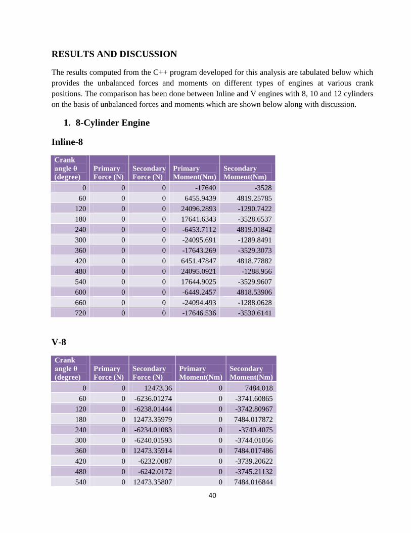
RESULTS AND DISCUSSION
The results computed from the C++ program developed for this analysis are tabulated below which
provides the unbalanced forces and moments on different types of engines at various crank
positions. The comparison has been done between Inline and V engines with 8, 10 and 12 cylinders
on the basis of unbalanced forces and moments which are shown below along with discussion.
1. 8-Cylinder Engine
Inline-8
Crank
angle θ
(degree)
Primary
Force (N)
Secondary
Force (N)
Primary
Moment(Nm)
Secondary
Moment(Nm)
0 0 0 -17640 -3528
60 0 0 6455.9439 4819.25785
120 0 0 24096.2893 -1290.7422
180 0 0 17641.6343 -3528.6537
240 0 0 -6453.7112 4819.01842
300 0 0 -24095.691 -1289.8491
360 0 0 -17643.269 -3529.3073
420 0 0 6451.47847 4818.77882
480 0 0 24095.0921 -1288.956
540 0 0 17644.9025 -3529.9607
600 0 0 -6449.2457 4818.53906
660 0 0 -24094.493 -1288.0628
720 0 0 -17646.536 -3530.6141
V-8
Crank
angle θ
(degree)
Primary
Force (N)
Secondary
Force (N)
Primary
Moment(Nm)
Secondary
Moment(Nm)
0 0 12473.36 0 7484.018
60 0 -6236.01274 0 -3741.60865
120 0 -6238.01444 0 -3742.80967
180 0 12473.35979 0 7484.017872
240 0 -6234.01083 0 -3740.4075
300 0 -6240.01593 0 -3744.01056
360 0 12473.35914 0 7484.017486
420 0 -6232.0087 0 -3739.20622
480 0 -6242.0172 0 -3745.21132
540 0 12473.35807 0 7484.016844

41
600 0 -6230.00636 0 -3738.00482
660 0 -6244.01825 0 -3746.41195
720 0 12473.35657 0 7484.015944
The primary force for both configurations is zero but the primary moment is zero only in V-8
engine. Hence V-8 engine is balanced for both primary forces and moments, but there are higher
secondary forces and moments as compared to inline-8. Since primary forces and moments are
more dominating over the secondary ones, hence the V-8 engine is better balanced than inline-8.
2. 10-Cylinder Engine
Inline-10
Crank
angle θ
(degree)
Primary
Force (N)
Secondary
Force (N)
Primary
Moment(Nm)
Secondary
Moment(Nm)
0 0 0 4286.52 -7472.304
60 0 0 -47646.283 3146.12747
120 0 0 -51935.352 4326.51313
180 0 0 -4291.8469 -7472.1777
240 0 0 47643.2755 3144.86514
300 0 0 51937.671 4327.64904
360 0 0 4297.17382 -7472.0512
420 0 0 -47640.267 3143.6027
480 0 0 -51939.99 4328.7848
540 0 0 -4302.5007 -7471.9244
600 0 0 47637.2587 3142.34015
660 0 0 51942.3077 4329.92041
720 0 0 4307.8275 -7471.7973
V-10
Crank
angle θ
(degree)
Primary
Force (N)
Secondary
Force (N)
Primary
Moment(Nm)
Secondary
Moment(Nm)
0 0 0 1980.09 -5907.38501
60 0 0 1980.09 4615.793989
120 0 0 1980.09 1292.084861
180 0 0 1980.09 -5907.74061
240 0 0 1980.09 4615.023687
300 0 0 1980.09 1293.210681
360 0 0 1980.09 -5908.09601
42
420 0 0 1980.09 4614.253226
480 0 0 1980.09 1294.336457
540 0 0 1980.09 -5908.4512
600 0 0 1980.09 4613.482606
660 0 0 1980.09 1295.462189
720 0 0 1980.09 -5908.8062
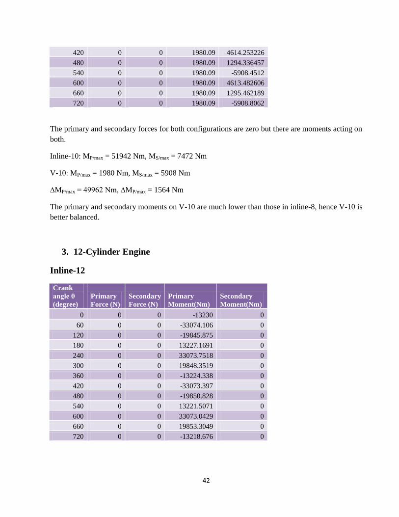
The primary and secondary forces for both configurations are zero but there are moments acting on
both.
Inline-10: MP/max = 51942 Nm, MS/max = 7472 Nm
V-10: MP/max = 1980 Nm, MS/max = 5908 Nm
∆MP/max = 49962 Nm, ∆MP/max = 1564 Nm
The primary and secondary moments on V-10 are much lower than those in inline-8, hence V-10 is
better balanced.
3. 12-Cylinder Engine
Inline-12
Crank
angle θ
(degree)
Primary
Force (N)
Secondary
Force (N)
Primary
Moment(Nm)
Secondary
Moment(Nm)
0 0 0 -13230 0
60 0 0 -33074.106 0
120 0 0 -19845.875 0
180 0 0 13227.1691 0
240 0 0 33073.7518 0
300 0 0 19848.3519 0
360 0 0 -13224.338 0
420 0 0 -33073.397 0
480 0 0 -19850.828 0
540 0 0 13221.5071 0
600 0 0 33073.0429 0
660 0 0 19853.3049 0
720 0 0 -13218.676 0
43
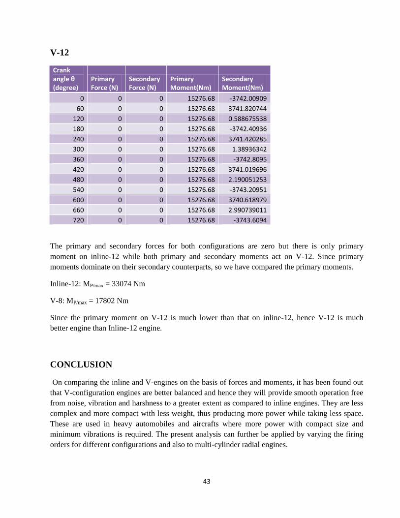
V-12
Crank angle θ (degree)
Primary Force (N)
Secondary Force (N)
Primary Moment(Nm)
Secondary Moment(Nm)
0 0 0 15276.68 -3742.00909
60 0 0 15276.68 3741.820744
120 0 0 15276.68 0.588675538
180 0 0 15276.68 -3742.40936
240 0 0 15276.68 3741.420285
300 0 0 15276.68 1.38936342
360 0 0 15276.68 -3742.8095
420 0 0 15276.68 3741.019696
480 0 0 15276.68 2.190051253
540 0 0 15276.68 -3743.20951
600 0 0 15276.68 3740.618979
660 0 0 15276.68 2.990739011
720 0 0 15276.68 -3743.6094
The primary and secondary forces for both configurations are zero but there is only primary
moment on inline-12 while both primary and secondary moments act on V-12. Since primary
moments dominate on their secondary counterparts, so we have compared the primary moments.
Inline-12: MP/max = 33074 Nm
V-8: MP/max = 17802 Nm
Since the primary moment on V-12 is much lower than that on inline-12, hence V-12 is much
better engine than Inline-12 engine.
CONCLUSION
On comparing the inline and V-engines on the basis of forces and moments, it has been found out
that V-configuration engines are better balanced and hence they will provide smooth operation free
from noise, vibration and harshness to a greater extent as compared to inline engines. They are less
complex and more compact with less weight, thus producing more power while taking less space.
These are used in heavy automobiles and aircrafts where more power with compact size and
minimum vibrations is required. The present analysis can further be applied by varying the firing
orders for different configurations and also to multi-cylinder radial engines.

44
REFERENCES
[1] Vigen H. Arakelian and M. R. Smith ,Shaking Force and Shaking Moment Balancing of
Mechanisms: A Historical Review With New Examples Journal of Mechanical Design, MARCH
2005, Vol. 127, pp 334-339
[2] I. Esat , H. Bahai, A theory of complete force and moment balancing of planer linkage
mechanisms, Mechanism and Machine Theory 34 (1999) 903-922
[3] W Harry Close, Wieslaw Szydlowski and Christopher Downton, Perfect Engine Balance Via
Collins Scotch Yoke Technology, SAE International, 941039 ,March 1994
[4] H. D. Desai, Computer Aided Kinematic and Dynamic Analysis of a Horizontal Slider Crank
Mechanism Used For Single-Cylinder Four Stroke Internal Combustion Engine, Proceedings of the
World Congress on Engineering 2009 Vol II WCE 2009, July 1 - 3, 2009, London, U.K.
[5] V. Arakelian and M. Dahan, Partial shaking moment balancing of fully force balanced linkages,
Mechanism and Machine Theory, Volume 36, Issues 11-12, November 2001, Pages 1241-1252
[6] J. Singh, B. Singh, Design of crankshaft for complete balancing of primary unbalanced force in
reciprocating engine, Journal of the Institution of Engineers (India), Part MC, Mechanical
Engineering Division. Vol. 82, no. 3, Oct. 2001, pp. 138-142.
[7] Mechanisms & Dynamics of machinery:Mable & Reinholtz
[8] Therory of machines :S S Rathan
[9] Theory of machines:Abdulla Shariff
[10] Theory of machines & mechanism :Ghosh & Mallick

45