Computational Forensic Analysis for the Chemical Weapons ...4... · Computational Forensic Analysis...
19
Computational Forensic Analysis for the Chemical Weapons Attack at Khan Sheikhoun on April 4, 2017 Goong Chen 1,2,3 , Cong Gu 1 , Theodore A. Postol 4 , Alexey Sergeev 1 , Sanyang Liu 5 , Pengfei Yao 6,7 , and Marlan O. Scully 2,8,9 1 Department of Mathematics, Texas A&M University, College Station, TX 77843, USA 2 Institute for Quantum Science and Engineering, Texas A&M University, College Station, TX 77843, USA 3 School of Mathematics and Statistics, Xidian University Xi’an 710071, China, on sabbatical leave from Texas A&M University 4 Program on Science, Technology, and National Security Policy (Emeritus), Massachusetts Institute of Technology, Cambridge, MA 02139, USA 5 School of Mathematics and Statistics, Xidian University, Xi’an 710071, China 6 Key Laboratory of Systems and Control, Institute of Systems Science, Academy of Mathematics and Systems Science, The Chinese Academy of Sciences, Beijing 100190, China 7 School of Mathematical Sciences, University of Chinese Academy of Sciences, Beijing 100049, China 8 Mechanical and Aerospace Engineering, Princeton University, Princeton, NJ 08544, USA 9 Baylor Research and Innovation Collaborative, Baylor University, Waco, TX 76798, USA Abstract Advances in computational mathematics and mechanics provide a potentially powerful new forensic tool to reconstruct impacts, crashes and bombings, including those during military operations. This article applies these new tools to revisit the use of sarin gas or a similar chemical weapon on April 4, 2017 at Khan Sheikhoun in Idlib, Syria. Details of the attack are disputed; claims by the United States and the Organization for the Prohibition of Chemical Weapons–United Nations Joint Investigative Mechanism that the attack was carried out by the Syrian Air Force are contested by Syria and by Russia. To advance and clarify this debate, this article uses forensic computer simulations, including the LS-DYNA general purpose finite element analysis code from the Livermore Software Corporation, and 3D image analysis to model the crater that was identified as the source of the sarin release. Modeling of an artillery rocket and warhead, including the high explosives, and the paved road it struck suggests the observed crater and fragments could have been due to an improvised rocket-propelled artillery round with a high-explosive warhead. This calls into question the scenario of the attack described by the Joint Investigative Mechanism, which suggested that this crater was created by an aerial bomb and used that conclusion to assign the Syrian government responsibility for the chemical attack. 1
Transcript of Computational Forensic Analysis for the Chemical Weapons ...4... · Computational Forensic Analysis...
Computational Forensic Analysis for the Chemical Weapons Attack
at Khan Sheikhoun on April 4, 2017
Goong Chen1,2,3, Cong Gu1, Theodore A. Postol4, Alexey Sergeev1, Sanyang Liu5, PengfeiYao6,7, and Marlan O. Scully2,8,9
1Department of Mathematics, Texas A&M University, College Station, TX 77843, USA2Institute for Quantum Science and Engineering, Texas A&M University, College Station, TX 77843, USA3School of Mathematics and Statistics, Xidian University Xi’an 710071, China, on sabbatical leave from
Texas A&M University4Program on Science, Technology, and National Security Policy (Emeritus), Massachusetts Institute of
Technology, Cambridge, MA 02139, USA5School of Mathematics and Statistics, Xidian University, Xi’an 710071, China
6Key Laboratory of Systems and Control, Institute of Systems Science, Academy of Mathematics andSystems Science, The Chinese Academy of Sciences, Beijing 100190, China
7School of Mathematical Sciences, University of Chinese Academy of Sciences, Beijing 100049, China8Mechanical and Aerospace Engineering, Princeton University, Princeton, NJ 08544, USA9Baylor Research and Innovation Collaborative, Baylor University, Waco, TX 76798, USA
Abstract
Advances in computational mathematics and mechanics provide a potentially powerful new forensictool to reconstruct impacts, crashes and bombings, including those during military operations. Thisarticle applies these new tools to revisit the use of sarin gas or a similar chemical weapon on April 4,2017 at Khan Sheikhoun in Idlib, Syria. Details of the attack are disputed; claims by the United Statesand the Organization for the Prohibition of Chemical Weapons–United Nations Joint InvestigativeMechanism that the attack was carried out by the Syrian Air Force are contested by Syria and byRussia. To advance and clarify this debate, this article uses forensic computer simulations, includingthe LS-DYNA general purpose finite element analysis code from the Livermore Software Corporation,and 3D image analysis to model the crater that was identified as the source of the sarin release. Modelingof an artillery rocket and warhead, including the high explosives, and the paved road it struck suggeststhe observed crater and fragments could have been due to an improvised rocket-propelled artillery roundwith a high-explosive warhead. This calls into question the scenario of the attack described by the JointInvestigative Mechanism, which suggested that this crater was created by an aerial bomb and used thatconclusion to assign the Syrian government responsibility for the chemical attack.
1
1 Introduction
One of the largest U.S. military operations in 2017 occurred on April 7, when the United Stateslaunched 59 Tomahawk cruise missiles from an Aegis cruiser, the USS Porter, against the Syriangovernment’s airbase at Shayrat, Syria. This attack was aimed at punishing the Syrian Governmentfor an alleged sarin nerve agent attack that had taken place seventy two hours earlier. The allegedattack took place on the morning of April 4, 2017 between 6 and 7 a.m. at Khan Sheikhoun (or,Khan Shaykhoun) in the Idlib Governorate of Syria. At the time the town was under the controlof Tahrir al-Sham, previously known as the al-Qaeda affiliated al-Nusra Front. Press and socialmedia reports based on information obtained from the local sources claimed that more than 80people were killed and 500–600 people were injured.
The use of “sarin or a sarin-like substance” was later confirmed by the Organization for theProhibition of Chemical Weapons (OPCW) Fact Finding Mission. Since the evidence examinedby the mission included information and materials provided by the Syrian Government, the use ofchemical weapons on that day is not questioned [1, p. 1]. Other details of the incident, however,have been in dispute. A summary of the U.S. Intelligence Community’s assessment released on11 April 2017 stated that the United States is confident that it was “a chemical weapon attack,using the nerve agent sarin,” carried out by the Syrian Government [2]. The OPCW-UN JointInvestigative Mechanism (JIM) in its 26 October 2017 report also concluded that “the SyrianArab Republic is responsible for the release of sarin at Khan Shaykhun on 4 April 2017” [3, para46]. The Government of Syria disputed that finding and stated that no aircraft of the Syrian AirForce attacked Khan Sheikhoun at the time of the incident [3, para 42]. The Russian Governmentalso questioned the JIM conclusions and criticized the methodology employed by the Mechanism.At the 16 November 2017 session of the UN Security Council Russia vetoed an extension of theJoint Investigative Mechanism’s mandate when the Council did not support the proposal thatRussia argued would strengthen the investigative protocols [4]. As a result, the conclusion aboutresponsibility for the sarin attack in Khan Sheikhoun remains contested.
One of the reasons the doubts about the JIM conclusion and the earlier U.S. assessment persistis the lack of transparency regarding some of the key aspects of the investigations. The UnitedStates cited the need to protect sources and methods to justify withholding of the informationthat was used in the assessment. The JIM investigation presented more details about the incident,but did not fully explain the basis for reaching some of its key conclusions. The central piece ofphysical evidence that has been linked to the attack is a crater in the middle of an asphalt coveredroad in the northeast corner of Khan Sheikhoun. The White House intelligence report, the OPCWFact-Finding Mission, and the JIM report point to this crater as the source of the sarin release.The JIM report further stated that “the crater had most likely been caused by a heavy objecttravelling at high velocity, such as an aerial bomb with a small explosive charge” [3, para 40].In combination with the data about operations of the Syrian Air Force, this finding was used tosupport the conclusion about the chemical weapon release being a result of an air attack.
As noted earlier, none of the reports about the incident provide firm evidence in support of theirclaims about the origin of the crater. The JIM report stated that the Mechanism examined eightpossible scenarios of the incident and conducted investigations into two of them - an aerial bomband an improvised explosive device placed on the ground [3, para 38]. The analysis of the craterappears to have been limited to a review of photographs, videos and satellite images conducted byexperts engaged by the Mechanism [3, para 40].
The objective of this paper is to provide an analysis that raises questions about the link between
2
the crater and an aerial bomb. The results of this analysis indicate that the crater that was identifiedas the source of a chemical release could have been generated by an improvised artillery rocket armedwith a high-explosive warhead. It is not known if this scenario was among the eight examined bythe JIM investigation and, if it was, on what basis it was excluded from detailed consideration. TheJIM report cites opinions of experts who assessed that it is unlikely that the crater was created bya ground-launched weapon [3, Annex II, paras 50, 52]. However, this scenario was not discussed indetail and as the analysis presented in this paper demonstrates the evidence cited by the expertsto support their conclusion does not in fact rule out the possibility of an artillery rocket explosion.
This paper examines the connections between evidence as observed at the scene and the physicalsequence of events. It is done by means of computerized reconstruction and reenactment. Thisapproach to event reconstruction is similar to that used in traditional forensic analyses of ballistics,except in this case we use advanced computational techniques to reconstruct the critical relevantfeatures of the scene of the incident.
The organization of the paper is as follows:
(1) Section 2 considers the photographic evidence collected at the scene and selects images thatshow the crater at various points of time;
(2) Section 3 presents the results of detonation and impact simulations of a 122 mm rocket-propelled artillery explosion that shows that the cratering and projectile effects are consistentwith the evidence observed at the scene. The crack pattern in the expended rocket motorcasing indicates manufacturing defects that mean that the rocket was most likely made locally.These are done by the computer-modeling software LS-DYNA;
Concluding Remarks are given in Section 4. Concise technical details of the modeling andprocessing are deferred to Appendices I and II, especially the validation part.
Computer modeling, coding, supercomputing and visualization is a challenging activity, as eachsupercomputer run can easily take 3–5 days. Problems of such fast dynamics with detonation anddestruction are well known to have high numerical instability and often tend to either diverge orproduce physically inconsistent results. Fortunately, a prior paper [5] from the investigation of therapid crash dynamics of the Germanwings Flight 9525, by incorporating the FEA (finite elementanalysis) and SPH (smooth particle hydrodynamics), has paved the foundation for validation andthen the eventual success of the computational work presented here. Important video animationsare included with their URLs and are must-sees for the reader in order to understand the underlyingdynamics.
2 Photographic evidence
Since the attack occurred in a rebel-controlled zone, it was not accessible for inspection and evalua-tion by neutral parties (i.e., UN inspectors) due to the lack of guaranteed safe passage. Photographsof the crater provide the only available data for close examination.
The representative set of images of the crater was selected from the large number of imagesthat were published in online media sources. The sources of the pictures and their sizes are listedin Table 2.1. The images are divided in two groups: (A) without a red skeletal marker, and (B)showing a rectangular red skeletal marker. In the latter group, the images show some signs ofadvanced disintegration of the crater along its border, see the comparisons below. This indicatesthat that the pictures in Group (B) were taken later than those in Group (A).
3

Image Web address Size (pixels)
A1 https://pbs.twimg.com/media/C8kEBpkXUAAXz1b.jpg 1200x800A2 https://www.dr.dk/images/other/2017/04/08/scanpix-20170405-090310-l.jpg 3500x2333A3 https://cdni.rt.com/russian/images/2017.08/original/59945338370f2ceb238b456e.jpg 1800x1000A4 https://pbs.twimg.com/media/C-0fQqJXYAAfJmr.jpg 1136x852B1 http://img.zeit.de/politik/ausland/2017-04/militaerschlag-syrien-donald-trump-giftgasanschlag-luftschlag-opposition-3/wide__1300x731 1300x731B2 https://i1.wp.com/rfsmediaoffice.com/en/wp-content/uploads/2017/04/4032.jpg?ssl=1 1920x1152B3 https://i.ytimg.com/vi/AqBqDzvtP-M/maxresdefault.jpg 1280x720
Table 2.1: Sources and sizes of the crater images to be analyzed.
The photographs show a metal fragment that resembles a shattered and bent pipe within itthat could be the remnant of vessel that was the source of the sarin release and/or the munitionthat created the crater. The pipe is bent along its length and appears to be split open along aseam running parallel to its centerline. A number of other objects could be seen in the crater aswell. However, the bent metal fragment is the only object that can be reliably linked to the crateras it is embedded into the ground unlike other fragments.
Comparison of the photographs from the two groups shows that the scene was modified at somepoint.
Pictures (A4) and (B2) were apparently taken from similar points of view and at the same timeof day. This allows comparing them side-by-side; see Figure 2.1. The comparison shows that theborder of the crater expanded in (B2) vs. (A4) by cracking, collapsing of pavement and chippingof crack edges. This advanced deterioration of the pavement indicates that the picture (B2) wastaken at a later time. Considerable bending of the pipe on (B2) vs. (A4) as well as disappearanceof loose debris on the pavement clearly shows that the site was modified after the image (A4) wastaken.
Figure 2.1: Comparison of the images (A4) (left panel) and (B2) (right panel). The observeddifferences in the crater shape are marked by yellow arrows. The orange arrow shows the bendingdirection of the pipe in image (B2). To make the comparison easier, the perspective of the image(A4) was slightly distorted (by approximately 10%) in order to make locations of four points (1–4)on the border of the crater exactly match in two images.
The most important change is the different bending directions of the top of the pipe: it pointsoutward of the crater in (A4) and inward of the crater on (B2). Visual signs of modification areconfirmed by a 3D image analysis, which is described in Appendix I.
The bending direction of the metal fragment plays an important role in the subsequent analysis.
4

The images of undisturbed site suggest that the twisted and broken pipe remnant was embeddedat the forward edge of the crater during the impact process. The computer simulation describedin the next section suggests that this could result from twisting of the metal motor casing alongits length due to the sudden torque generated when the ground suddenly arrested the horizontalmotion of the front of the casing while the rear was free to rotate forward.
3 Computational Forensics on Cratering from Computer Model-ing with LS-DYNA
For the purposes of this analysis we followed the assumption made by Postol [6], who first observedand assessed that the metal fragment in the crater looks like a remnant of an improvised sarindispenser made from a 122 mm artillery rocket. We hereby again closely examined the crater andthe fragment and came to the same assessment. Unfortunately, due to the lack of access to thephysical site that assumption cannot be positively confirmed. However, the results of the computersimulation presented here suggest that this assumption is consistent with the physical evidencefrom the site.
An improvised 122 mm artillery rocket would use an industrially produced high-explosive war-head. Common variants of these warheads weigh about 18 kg and have about 6.5 kg explosivecharge. The exact weight of the charge in these easily purchased warheads varies somewhat butthe explosive effects of charges of slightly different weights are essentially irrelevant to the find-ings shown in our calculations. Key parameters of the munition that was used in our computersimulations are given in Table 3.1.
The table also lists parameters of the impact that are based on the assumptions about themunition trajectory. Since the rocket motor casing (as seen in the photos of Section 2) is relativelysmall, we can assume that the rocket probably has a range of around 4–5 km. The angle at impactcan have a range of 45°–70°.
To conduct simulation of the explosion we used the LS-DYNA tool [7], the chief commercial-ized product of computer modeling software made by the Livermore Software Corporation withmore than forty-years history of development. Technical details of the simulation are provided inAppendix II. All the computations have been carried out on the ADA and Curie clusters at TexasA&M University’s High Performance Computing Center. Each run took about three days or longer.
Parameter Value
Total weight of rocket 27 kgWeight of TNT H.E. 8.1 kgWeight of warhead metal 10.1 kgTerminal velocity 220 m/sAngle 65°
Table 3.1: Parameters for the calculation of a 122 mm rocket warhead impact on an asphalt road.
We include Figure 3.1 with the sequence of six snapshots extracted from a video animation asthe visualization output of our supercomputer results. The panels show the motion sequence, whichleads to the end result of similarly what is observed in the photographs in the left column of FigureI.1. The frontal portion of the spent motor casing of the rocket is embedded in the soil near the
5

Figure 3.1: This simulation contains the key assessment of this article. The snapshots show theimpact and explosion of a 122 mm artillery rocket. The rocket casing has manufacturing de-fects, causing a linear crack on a generatrix. The crater has a rough diameter of about 1.2m and the remnant pipe has about 0.5 m above ground. The depth scale is in millimeters.For dynamic visualization, see the video in https://www.dropbox.com/sh/mve31ivwl5tz0nx/
AAAKMaXCqp0x-GaKEAYZ2g0Pa?dl=0&preview=BlastSR2-J5A-HD.mp4 .
edge of the crater, which matches the position of the metal fragment as seen on images that showthe crater before it was modified. The fragment is slightly bent forward and is pointing outwardby the sudden torque that occurs when the warhead impacts and then becomes lodged under theasphalt surface. If we assume that the rocket casing was fabricated into a pipe by welding, ourcalculations show similarly the kind of split or fissure along a generatrix of the pipe - the line onthe cylinder parallel to its axis.
A close inspection of the back end of the embedded rocket motor casing shows an increase in theforward pointing curvature of the pipe and a fracture along the end-axis of the pipe from extreme
6
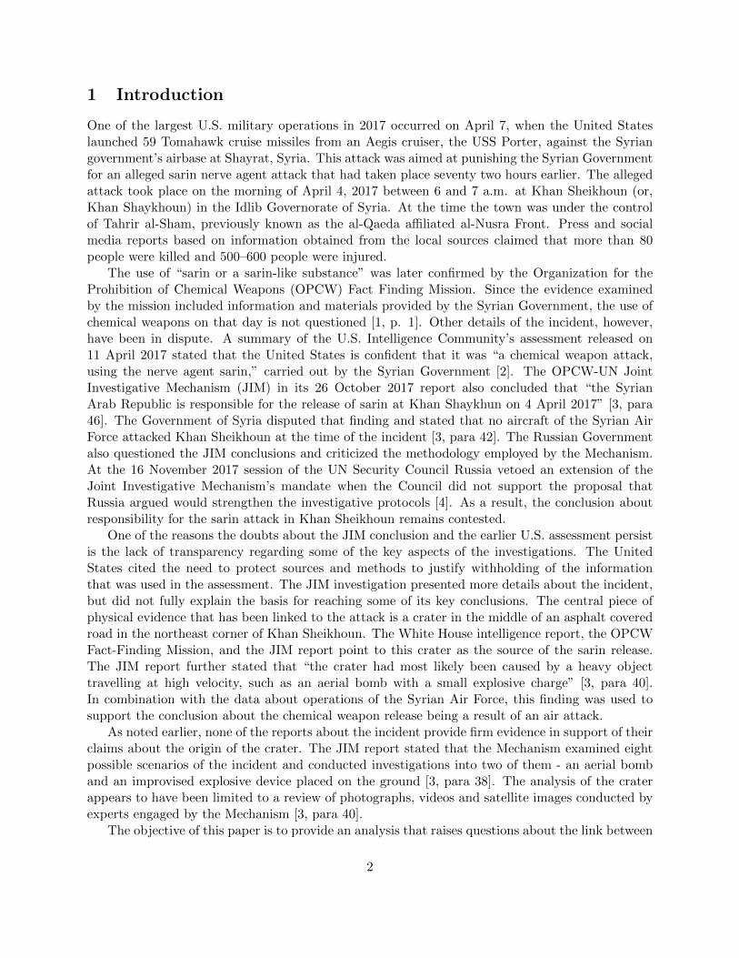
Figure 3.2: A zoomed-in view of the pipe in Figure 3.1.
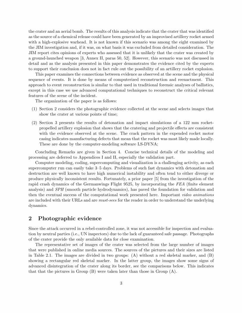
Figure 3.3: A snapshot of a 122 mm artillery rocket upon impact and explosion. This rocketis computed by using the same physical parameters as in Table 1, except that it does not havemanufacturing defects. One sees no crack on the rocket casing. For dynamic visualization, see thevideo in https://www.dropbox.com/sh/mve31ivwl5tz0nx/AAAKMaXCqp0x-GaKEAYZ2g0Pa?dl=0&
preview=BlastSR2-J6A-HD.mp4.
pulling forces. We believe that the extreme pulling forces that increased the curvature and causedthe fracture of the rear pipe edge were the result of an attached nozzle and fin section being tornoff during the extreme horizontal velocity deceleration at impact.
It is well known that cracks and fracture occur and propagate along the lines and locationswhere structural weakness and micro cracks preexist. The nearly linear crack split on the rocketmotor casing (i.e., pipe) is due to the impact damage on the structure and then the propagation ofthe crack. The case computed in Figure 3.1 assumes the preexistence of structural weakness alonga generatrix of the cylinder, due to possible welding in the fabrication of a pipe. The “line crack”can be seen in Figure 3.2 as a zoomed-in view of the pipe in Figure 3.1. We then have computedan additional case under exactly the same assumptions and with identical choices of parameters,but without any preexisting structural weakness on the pipe. The results show that the carcassthen does not have a nearly linear crack; see Figure 3.3.
The arrival azimuth is easily identified because the rocket is embedded at the forward edge/sideof the crater and the bent spent rocket casing also points forward along the direction of arrival.The cracking of the asphalt surface surrounding the crater, clearly visible with a radiative pattern,is due to hot gases propagating through the underlying ground and pushing the asphalt vertically.
7

We should emphasize that the calculations do not necessarily capture all possible inhomo-geneities of the asphalt surface or of the ground underneath. Nevertheless, the computationalmathematics and mechanics calculation essentially predicts most or all of the observed features ofthe crater at Khan Sheikhoun.
The Joint Investigative Mechanism appears to have looked into the scenario which assumedthat the crater was produced by a “ground-launched” weapon or munition, although the reportprovides no details about specific assumptions made by the experts engaged by the JIM. Twoseparate arguments were made to exclude that scenario from consideration. First, it was statedthat “no remnants peculiar to a rocket had been evident in the crater or found in its vicinity” [3, para50]. This analysis, however, demonstrates that the metal fragment embedded in the crater could,in fact, be a remnant of an improvised rocket. It should be noted that no fragments characteristicof an aerial bomb, such as tail fins, were present at the site either. More importantly, since theaccess to the site was not restricted and, as we demonstrated earlier, it was modified after thecrater was formed, the absence or, indeed, presence of fragments at the site that are not embeddedin the ground cannot be used to support this conclusion in the JIM report.
Another argument made by the experts engaged by the JIM cites the scarcity of “visible signsof damage caused by fragmentation or overpressure, especially on the metal cabinet located 3 to5 m away from the crater” [3, para 54]. Although it is not clear from the report, it appears thatthis observation applies to one of specific scenarios considered by the JIM, namely the one in whichthe crater was created by an explosive charge placed on the ground. In this scenario one indeedwould expect to see a certain damage to the metal cabinet. However, in the scenario consideredhere, it should be taken into account that a cylindrical explosive charge, such as a 122-mm warheadconsidered in this analysis, would not produce a spherically-symmetrical blast wave or a debriscloud. For munitions with a high length-to-diameter ratio most debris would be distributed inan annular pattern that is perpendicular to the munition axis (pointed forward if the motion ofthe munition is taken into account). This effect, in fact, can be seen on the second panel of theexplosion sequence shown on Figure 3.1. The location of the metal cabinet placed it in the solidangle that is unlikely to be affected by the explosion debris.
It therefore can be stated with substantial confidence that the observed crater is consistent withthe impact of an improvised rocket that used a standard 122 mm explosive warhead. If that isthe case, the munition that created the crater could not have been used as a sarin delivery device,since in the model considered in this analysis, the volume of the improvised rocket would be usedup by the propellant and the explosive warhead. The split pipe that the JIM report identified asevidence of a container filled with sarin is simply the casing of the rocket motor that propelled thewarhead to the location of the explosion.
4 Concluding Remarks
This paper demonstrated the use of a powerful new forensic tool based on computational mathe-matics and mechanics that allowed us to model characteristics of the munition that was used inthe attack on the civilian population of Khan Sheikhoun on the morning of April 4, 2017. Wehave shown that the crater that the OPCW Fact Finding Mission and the UN-OPCW Joint In-vestigative Mechanism identified as the most likely point of release of sarin used in the attack isconsistent with the result of an explosion of an improvised artillery rocket armed with a small ex-plosive warhead. This calls into question the conclusions of the Joint Investigative Mechanism and
8

of the earlier White House report that linked the chemical weapons attack in Khan Sheikhoun toan aerial bomb. Since that link was an important factor in attributing the use of chemical weaponsto an attack by the Syrian Air Force, it also raises questions about that attribution. An analysisof various scenarios of the incident, however, is beyond the scope of this article.
It is extremely important that the international community holds accountable the perpetra-tors of chemical attacks. For this to happen, it is essential to have an established investigationmechanism that could conduct impartial investigation of all incidents of alleged use of chemicalweapons. It is also essential to ensure that these investigations are based on scientifically soundanalysis and that that they are conducted in a transparent way. The investigation of the April 4,2017 incident in Khan Sheikhoun illustrates this point. In considering the formation of the craterthat is believed to be at the source of the sarin release the investigation was based exclusively on avisual examination of photo and video evidence. The methodology used by the experts engaged bythe Joint Investigative Mechanism to reach their conclusions was never explained. As the analysispresented in this paper demonstrates, there are scenarios of an incident that are consistent withthe observed evidence that would call into question the key conclusions of the JIM report regardingthe origin of the crater and potentially about the attribution of the attack.
Regrettably, the termination of the UN-OPCW Joint Investigative Mechanism mandate inNovember 2017 appears to have ended further attempts to investigate the incident in Khan Sheikhoun.We hope that this analysis will contribute to establishing of facts of that incident and will helpreliably identify the perpetrators of the chemical attack in Khan Sheikhoun.
Acknowledgement
S. Liu is partially supported by The National Natural Science Foundation of China Grant No.61373174. P. Yao is partially supported by The National Natural Science Foundation of ChinaGrants No. 61473126 and No. 61573342, and Key Research Program of Frontier Sciences, CAS,No. QYZDJ-SSW-SYS011. M.O. Scully is partially supported by The Robert A. Welch FoundationGrant No. A-1261. We thank Texas A&M University’s High Performance Computing Center forthe generous allocation of supercomputing hours on the Ada and Curie cluster.
References
[1] REPORT OF THE OPCW FACT-FINDING MISSION IN SYRIA REGARDING AN AL-LEGED INCIDENT IN KHAN SHAYKHUN, SYRIAN ARAB REPUBLIC APRIL 2017.June 2017. url: https://www.opcw.org/fileadmin/OPCW/Fact_Finding_Mission/s-1510-2017_e_.pdf (visited on 08/01/2018).
[2] The Assad Regime’s Use of Chemical Weapons on April 4, 2017. Apr. 2017. url: https://assets.documentcloud.org/documents/3553049/Syria-Chemical-Weapons-Report-
White-House.pdf (visited on 08/01/2018).
[3] Seventh report of the Organisation for the Prohibition of Chemical Weapons-United NationsJoint Investigative Mechanism. Oct. 2017. url: https://www.securitycouncilreport.org/atf/cf/%7B65BFCF9B-6D27-4E9C-8CD3-CF6E4FF96FF9%7D/s_2017_904.pdf (visitedon 08/01/2018).
9
[4] Security Council Meetings Coverage. Security Council Fails to Adopt 2 Draft Resolutions onExtending Mandate of Joint Mechanism Investigating Chemical Weapons Attacks in Syria.Nov. 16, 2017. url: https://www.un.org/press/en/2017/sc13072.doc.htm (visited on01/08/2018).
[5] G. Chen, Y.-C. Wang, A. Perronnet, C. Gu, P. Yao, B. Bin-Mohsin, H. Hajaiej, and M. O.Scully. “The advanced role of computational mechanics and visualization in science and tech-nology: analysis of the Germanwings Flight 9525 crash”. In: Physica Scripta 92.3 (2017),p. 033002.
[6] T. A. Postol. A Quick Turnaround Assessment of the White House Intelligence Report Issuedon April 11, 2017 About the Nerve Agent Attack in Khan Shaykhun, Syria. url: https:
//d.ibtimes.co.uk/en/file/99/postol-report-1.pdf (visited on 11/02/2017).
[7] LS-DYNA. Livermore Software Technology Company. url: http://www.lstc.com/products/ls-dyna.
[8] Y. Ma, S. Soatto, J. Kosecka, and S. S. Sastry. An Invitation to 3-D Vision: From Images toGeometric Models. Vol. 26. Springer Science & Business Media, 2012.
[9] R. Hartley and A. Zisserman. Multiple View Geometry in Computer Vision. Cambridge uni-versity press, 2003.
[10] J. Wu, L. Li, X. Du, and X. Liu. “Numerical study on the asphalt concrete structure for blastand impact load using the Karagozian and case concrete model”. In: Applied Sciences 7.2(2017), p. 202.
[11] E. L. Fasanella, K. H. Lyle, and K. E. Jackson. Developing soil models for dynamic impactsimulations. 2009. url: https://ntrs.nasa.gov/search.jsp?R=20090022374.
[12] J. Strange, C. Denzel, and T. McLane III. Cratering from High Explosive Charges. Analysisof Crater Data. Tech. rep. Army Engineer Waterways Experiment Station, Vicksburg, MS,1961.
Appendix I Corresponding Points, Epipolar Geometry and theFundamental Matrix
I.1 Movement of Bent Pipe Evidencing Changes to the Original Crater
This Appendix presents the results of a 3D image analysis based on calculation of the so calledfundamental matrix between images (A1)/(B1), as well as between (A1)/(B2) and (A1)/(B3). Asdiscussed in the paper, visible signs of crater degradation prove that the images in Group A weretaken earlier than those in Group B. We create the epipolar lines in the image (A1) that correspondto the location of the tip of the pipe in the images from Group (B). The intersection of epipolarlines shows the location of the tip of the pipe in the images from Group (B) as it would be seen inthe image (A1). Figure I.2 shows that the pipe has been bent in the images from Group (B) fromoutward to inward of the crater.
From a mathematical point of view, an image is a projective mapping of a three-dimensionalobject into a plane. Since two different images of the same object may be results of differentprojections, their comparison is not straightforward. However, locations of a given physical pointin two different images are closely related. Introducing homogeneous coordinates x ≡ (x, y, 1), as
10
Figure I.1: Eight corresponding points (1–8) in images (A1), (B1), (A2), (B2), (A3), and (B3).The point (T) marks the tip of the pipe.
in projective geometry, of a point (x, y) in the first image and x′ ≡ (x′, y′, 1) of the correspondingpoint (x′, y′) in the second image, this relationship can be expressed as the linear constraint [8, 9]
x′TFx = 0. (1)
The matrix F in (1) is called the fundamental matrix. It depends only on internal parameters ofthe cameras and their positions. If the location of a point in the second image, x′, is known, then
11
Figure I.2: The scene in image (A1) with epipolar lines showing re-projection of the tip of the (T)from the images of Group (B) into the image (A1), red, green and blue lines for (B1), (B2), and(B3) images, respectively. Red circle at their intersection shows the tip from Group (B) as it wouldbe seen in image (A1), as a point (T’). Bold green line connects points (1) and (T) and showsdirection of the pipe in Group (A), while the dashed line does in Group (B).
possible locations of the same point in the first image, x, may be anywhere on the line defined by(1). This line is known as epipolar line.
Our first task is calculating the fundamental matrix between two images using a set of eightpairs of corresponding points. We write down a set of eight homogeneous equations
x′(n)T
Fx(n) = 0, (2)
for each pair of corresponding points(x′(n),x(n)
), n = 1, . . . 8. Since F is 3 × 3 matrix with
8 unknown elements (we could always set F11 = 1 because of homogeneity of the equations), 8equations are generally sufficient to resolve the linear system for 8 unknowns.
The corresponding points of the images were selected manually as some prominent “landmark”points that are clearly visible in each photo and that are associated with solid and unmovablephysical objects. Our choice of corresponding points is shown in Figure I.1.
Appendix II LS-DYNA Computer Modeling of Explosion and Im-pact; Validation
Modeling and computation of the problem under consideration require fundamental mathematicalmodels like partial differential equations for aerodynamics (hot gas), solid dynamics (paved road),
12

fracture mechanics, explosion dynamics, and their interactions. By proper set-up, LS-DYNA isable to take all of them into account. This Appendix provides the foundation for modeling andcomputation methodologies for Section 3.
LS-DYNA is a general purpose finite element analysis software developed by LSTC [7]. It hasaccumulated numerous capabilities and functions that are powerful in simulating complex real-worldtransient dynamic problems such as crash and explosion. We have successfully used LS-DYNA forthe study just as in that for the pulverizing crash of Germanwings Flight 9525 [5], where it is foundthat a combination of Finite Element Analysis (FEA) and Smoothed Particle Hydrodynamics (SPH)can yield excellent results.
The problem of asphalt pavement under blast and impact load has been studied numericallyusing LS-DYNA by other researchers; see [10], for example. In the current study, we use solidelements to model the paved road, shell elements to model the structure of the artillery rocket, andSPH particles to model the warhead including the high explosives. The process of the explosion andimpact of the artillery rocket, consisting of a warhead and a motor pipe behind, can be described asfollows. The warhead explodes upon contact with the road, creating damage. The motor part thenkeeps moving downward and crashes into the ground. The basic spatial setup of the simulation isshown in Figure II.1. Details of the modeling of each component are discussed below.
Figure II.1: Overview of simulated parts.
Far field soil
Near field Soil
Sliding far field pavement
Far field pavementNear field pavement
Figure II.2: Section of paved ground model.
II.1 Modeling of Paved Road
The road is modeled as an asphalt pavement of 10 cm in thickness, and a soil foundation underneath.The pavement consists of three parts, the near field, the far field (coarse grids) and the sliding farfield. The sliding far field is tied to the soil underneath, but its tangential sliding is permitted. Thesoil is also modeled with a near field part and a far field part with a different grid size. See FigureII.2 for a cross-section of the ground. The material model for the asphalt chosen in LS-DYNA isMAT_CONCRETE_DAMAGE_REL3 with parameter generation, while the material model for the soil isMAT_SOIL_AND_FOAM. Major material parameters are shown in Table II.1.
13

Parameter Value
Density of asphalt 2320 kg/m3
Unconfined compression strength of asphalt 4.6 MPaStrain rate effect for asphalt [10, Figure 6]Maximum principal strain at erosion for asphalt 0.08Minimum principal strain at erosion for asphalt -0.08Density of soil 2100 kg/m3
Shear modulus of soil 60 MPaYield coefficients of soil [11, Table 2]Compressibility of soil [11, Figure 14]
Table II.1: Material parameters for the paved road.
II.2 Modeling an Artillery Rocket
The artillery rocket consists of a warhead and a motor. The warhead has a metal casing withhigh explosives inside. They are both modeled with SPH. The motor pipe has a longitudi-nal structural weakness intended to signify a welding seam, and is modeled by collocated nodestied with CONSTRAINED_TIE-BREAK. There is a strengthened edge (larger thickness) along theseam of the structural weakness. See Figure II.3. The material model of high explosive isMAT_HIGH_EXPLOSIVE_BURN. The important equation of state of high explosives is EOS_JWL (theempirical Jones-Wilkins-Lee equation of state), given by
p = A
(1 − ω
R1V
)e−R1V +B
(1 − ω
R2V
)e−R2V +
ωE
V.
The material model for steel is MAT_PLASTIC_KINEMATIC, whose strain rate effect is accounted forby the Cowper-Symonds model
σyσ0
= 1 +
(ε̇
C
)1/p
.
Major parameters are listed in Tables II.2 and II.3.
II.3 Contact Modeling
Contact settings are summarized in Table II.4. Erosion is enabled for the pavement to simulatedamage and perforation. The motor pipe has a “tie on contact” type of contact with the soil, whichis meant to simulate the fixation of the motor pipe in the ground after having lodged into the soil.Static frictional coefficient is set to be 0.8 and dynamic frictional coefficient is set to be 0.6 whereapplicable.
II.4 Validation of SPH Blast Simulation
Validation is a crucial, indispensable part of any computational mechanics study. The computeddata must be validated against those from experiments. Artillery rocket explosion damage dataare hard (or, nearly impossible) to come by. Therefore, we validated our explosion data versus the
14
Warhead
Motor structural weakness
Strengthened edge
975 mm
610 mm
Figure II.3: Schematic of an artillery rocket.
Parameter Value
Density 1630 kg/m3
Detonation velocity 6930 m/sChapman-Jouget pressure 21 GPaA in JWL 371.2 GPaB in JWL 2.23 GPaR1 in JWL 4.15R2 in JWL 0.95ω in JWL 0.3Initial E in JWL 7 GJ/m3
Initial V in JWL 1.0
Table II.2: Parameters for high explosive (TNT).
crater formation data from high-explosive blasts collected by the U.S. Army Corps of Engineers[12].
In this validation, we use Smoothed Particle Hydrodynamics (SPH) to simulate buried, contact(0 < λc < 0.053), and near field (0.053 < λc < 0.4) blast load, where λc is the reduced chargeposition with unit m/kg1/3. In our situation, λc ≈ 0.12 if the warhead is detonated upon groundimpact with a 45° landing angle.
In our validation simulation, we set up a ball-shaped 5 lb TNT charge at various locations abovethe soil. The shear modulus of soil is lowered to 20 MPa, from 60 MPa in Table II.1, which is meantto model a stronger gravel rich mixture. In Figures II.4(a) and (b), craters in our simulation arecompared with the cratering data collected by the U.S. Army Corps of Engineers [12]. The datamanifest that they lie well within the range of experiments.
15

Parameter Value
Density of Steel 7800 kg/m3
Young’s modulus 200 GPaPoisson’s ratio 0.29Yield stress 310 MPaTangent modulus 1 GpaKinematic hardening parameter 0.3C in Cowper-Symonds model 40 s−1
p in Cowper-Symonds model 5Effective plastic strain at erosion 0.7Motor thickness 3 mmMotor edge thickness 5 mmWarhead casing thickness 6 mm
Table II.3: Parameters for rocket steel parts.
Slave Master Contact
Warhead Pavement ERODING_NODES_TO_SURFACE
Warhead Other AUTOMATIC_NODES_TO_SURFACE
Motor Pavement ERODING_SURFACE_TO_SURFACE
Motor Soil AUTOMATIC_SURFACE_TO_SURFACE_TIEBREAK
(Option 1 – tie on contact)Sliding far field pavement Soil AUTOMATIC_SURFACE_TO_SURFACE_TIEBREAK
(Option 4 – slide)Near field pavement Far field pavement TIED_NODES_TO_SURFACE
Near field soil Far field soil TIED_NODES_TO_SURFACE
Other – AUTOMATIC_SINGLE_SURFACE
Table II.4: Contact settings.
16

0 0.05 0.1 0.15 0.2 0.2510
-1
100
λc (m/kg
1/3)
App
aren
t Cra
ter
Rad
ius
(m)
Observed Data Range for 0< λc<0.28
Reference Value
34k SPH Particles
268k SPH Particles
905k SPH Particles
(a)
0 0.05 0.1 0.15 0.2 0.25
10-1
100
λc (m/kg
1/3)
App
aren
t Cra
ter
Dep
th (
m)
Observed Data Range for 0< λc<0.28
Reference Value
34k SPH Particles
268k SPH Particles
905k SPH Particles
(b)
Figure II.4: Ball-shaped, 5 lb TNT charge detonated at various locations above the soil. Comparisonof (a) apparent crater radius, and (b) apparent crater depth with [12].
II.5 Modeling of Bomb-Detonation-on-the-Ground Scenarios
We used the technique to examine other potential scenarios of the crater formation. Postol [6]earlier suggested a blast configuration as shown in Figure II.5. The outcome of the blast shows atotally different damaged and fractured pipe than the one seen in the crater, Figures 2.1–I.2. Seealso the associated video animation link in the caption of Figure II.5.
Setting up the pipe and high-explosive stick in different configurations, as given in Figures II.6and II.7, only produces outcomes of a damaged and fractured pipe which look similar to that inFigure II.5(b). Therefore, this scenario was dismissed.
(a) (b)
Figure II.5: (a) A possible configuration first proposed by Postol [6]; (b) A snapshot where one cansee a totally different fracture pattern of the pipe. Thus, this configuration has been disproved.Video in https://www.dropbox.com/sh/mve31ivwl5tz0nx/AAAKMaXCqp0x-GaKEAYZ2g0Pa?dl=0&
preview=BlastSEC2-HD.mp4.
17

(a) (b)
Figure II.6: This layout between the explosive (on top) and the pipe is different from that in FigureII.5. However, the fracture pattern of the pipe is similar, which is different from the pipe on thecrater site so it is again dismissed. Video in https://www.dropbox.com/sh/mve31ivwl5tz0nx/
AAAKMaXCqp0x-GaKEAYZ2g0Pa?dl=0&preview=BlastSEC3-HD.mp4 .
18

(a) (b)
Figure II.7: Here the explosive is spherical. Again, the eventual crack pattern in(b) leads to its dismissal. Video in https://www.dropbox.com/sh/mve31ivwl5tz0nx/
AAAKMaXCqp0x-GaKEAYZ2g0Pa?dl=0&preview=BlastSEC4-HD.mp4 .
19