
Computational Fluid Dynamics CFD Simulations of Jet Mixing in Tanks of Different Scales
TensiNet Symposium 2003I 108 I
Numerical Simulations for Wind Load Design of Large Umbrellas
Abstract. Governing Wind Loads applied on fully
deployed large umbrellas are determined using
Computational Fluid Dynamics (CFD) simulations,
predicting the mast moments and drag and lift
forces.
Firstly, the static effect of the umbrella deforma-
tion is taken into account using an iterative proce-
dure where the umbrella deformation is computed
with a non-linear, static, implicit, finite element
code for the predicted wind load. Secondly, the
Dynamic Load Factor (DLF) to be used for the design
can be estimated by performing time-accurate cou-
pled Fluid Structure Interaction (FSI) simulations.
In these simulations the transient turbulent flow is
simulated with a CFD code around a flexible umbrel-
la model, using a non-linear dynamic finite element
code.
These simulations require a detailed geometrical
modelling of the structure and of the surrounding
buildings and topography, as well as an accurate
model for the turbulence in the atmospheric bound-
ary layer.
Eberhard Haug
P. de Kermel
P. Gélenne
ESI Software SA
99, rue des Solets, Silic 112
94513 Rungis Cedex
FRANCE
Email: [email protected]
www.esi.fr
Designing Tensile Architecture I 109 I
E. Haug
1 INTRODUCTION
Lightweight fabric structures are often used to protect people and equipment from the directsun light. Among the structures that are used for this purpose, such as roofs, screens, tentsor umbrellas, the latter have several specific architectural advantages. Firstly, with the base of the mast, an umbrella has only one point connected to the ground,where other kinds of structures usually require several fixation points. This feature is a bigadvantage in cases where the sun protecting device must have a minimal impact on the exist-ing buildings and the surrounding structures, and where it must not be an obstacle to people,vehicle traffic or to the view. Secondly, an umbrella is a retractable structure, allowing removalof the sunscreen for local climate control, or when it is not required or dangerous (e.g. duringthe night, in stormy weather conditions, etc). Because of these specific features, the umbrella must be carefully designed. Similar to mostlightweight structures, the wind loading is an important design loadcase. In the case ofumbrellas, the main resulting loads are the drag force, the lift force and the overturningmoment at the base of the mast. The precise determination of the governing wind load iscomplex since the wind deforms the fabric, which can modify the umbrella shape. The natureof the wind is inherently transient due to the atmospheric turbulences, hence dynamic effectsmust be included in the analysis. The atmospheric turbulences are generated by obstacles inthe atmospheric boundary layer. Finally, fluctuations from obstacles far from the umbrellamay be considered as random, but the wind perturbations in the wake of nearby obstaclesmust be modelled in a deterministic fashion.
2 STATIC WIND LOADS
Wind loads are among the most important for the umbrella design. In particular, the lift forceinduced by the shape of the umbrella must not be greater than the weight of the umbrella andfoundations. The foundations and the mast must resist the moments generated by the pres-sure gradient on the membrane roof, and by the wind drag force on the roof. Finally, theretractable membrane roof suspension system and the membrane roof itself must be designedto resist the static and dynamic wind loads.
2.1 WIND LOAD ESTIMATION ON RIGID UMBRELLA
2.1.1 NUMERICAL FORMULATION
In order to simulate the wind flow around the umbrellas, the PAM-FLOW™ [1] code is used. Inthis approach, the Reynolds Averaged incompressible Navier-Stokes (RANS) equations aresolved. The effects of turbulence are included using the Smagorinski SubGrid Scale (SGS)model, together with a law of the wall model at the boundaries. The spatial discretization isaccomplished using Finite Element techniques (Galerkin weighted residuals method) forunstructured linear 3D elements (tetrahedra). For the temporal discretization, a two step pre-dictor-corrector scheme is used (implicit pressure projection scheme): in the first step, velocityand pressure are predicted explicitly using a Roe flux splitting scheme, then, in the second step,the pressure is computed implicitly and the velocity is corrected from the updated pressure.
TensiNet Symposium 2003I 110 I
Numerical Simulations for Wind Load Design of Large Umbrellas
2.1.2 EXPERIMENTAL VALIDATION
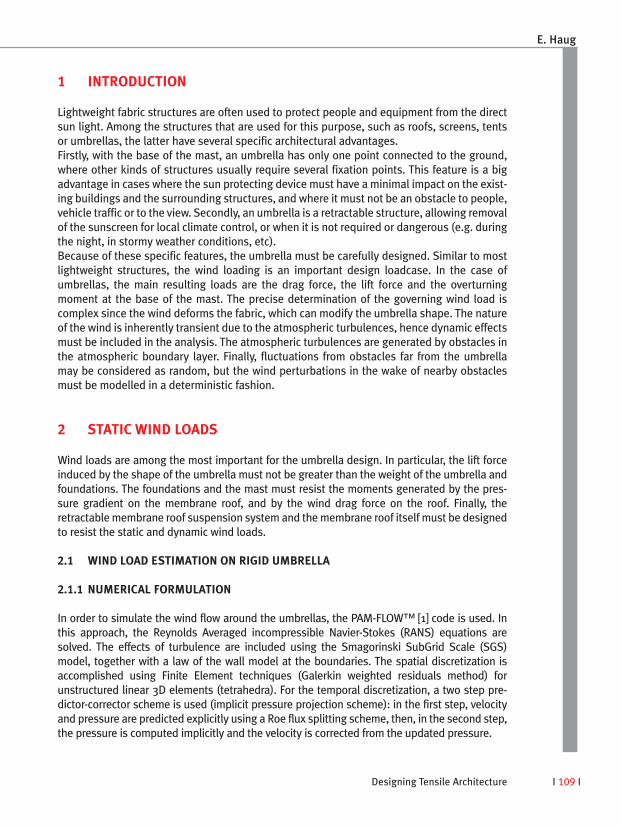
As a preliminary step, it is useful to compare the predicted results with those from windtunnel experiments. This allows a check on whether the model’s numerical parameters(e.g. mesh size, etc.) are appropriate for the studied configuration. This is also useful to ensure that the results from both methods are consistent, and can beused together and efficiently in the overall wind load design process. For example, oncethe scaled-down wind tunnel mock-up model is prepared, it is possible to perform in a rel-atively short time measurements for several wind directions. Numerical methods willrequire less delay to prepare the model, but each wind direction will take about the sametime to be computed - such that the computation of many wind directions may take longerthan the wind tunnel alternative. However, it is much more difficult to model flexible,scaled-down structures using wind tunnel experiments. Figure 1 presents an example of experimental and simulation results. The results presented are the distribution of the mean wind pressure coefficient on the internal andexternal surfaces. In the experiment, measurements could not be made close to the central mast or to the umbrella edges. Except at these locations, the comparison is seento be very good.
2.2 WIND LOAD ESTIMATION ON DEFORMING UMBRELLA
In the case of umbrellas, it is not sufficient to determine the wind load for the rigid umbrel-la shape. Even small mast deformations, and local deformations of the roof and of its sus-pension system can increase the angle of incidence. Hence the wind resistance of thestructure will increase, with the resulting increase in the critical design forces andmoments at the base of the mast.
2.2.1 QUASI-STATIC STEADY-STATE WIND LOAD SIMULATION
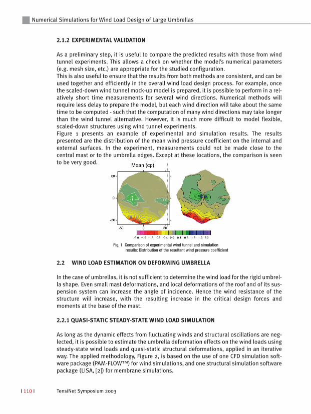
As long as the dynamic effects from fluctuating winds and structural oscillations are neg-lected, it is possible to estimate the umbrella deformation effects on the wind loads usingsteady-state wind loads and quasi-static structural deformations, applied in an iterativeway. The applied methodology, Figure 2, is based on the use of one CFD simulation soft-ware package (PAM-FLOW™) for wind simulations, and one structural simulation softwarepackage (LISA, [2]) for membrane simulations.
Fig. 1 Comparison of experimental wind tunnel and simulationresults: Distribution of the resultant wind pressure coefficient
Designing Tensile Architecture I 111 I
First, a steady-state wind simulation is performed around the rigid undeformed umbrellawith the flow code. The wind pressure load obtained is then used to determine the quasi-static umbrella deformations using the structure code. Then a new wind simulation is per-formed with the flow code, using the new deformed (rigid) umbrella shape. This processis repeated until successive iterations do no longer significantly change the wind load andthe deformations, as shown, for example, in Figure 3.
2.2.2 RESULTS
The iterative coupling methodology between LISA and PAM-FLOW™ has been developedand demonstrated in the DELITE European project [3,4], and specific tools to automatical-ly define the pressure load in LISA and update the PAM-FLOW geometry have been devel-oped. The methodology was applied to evaluate the wind load on a simple fabric roof (SLGmbH, Canobbio SpA). Figure 3 presents the convergence curve, based on the drag force.Figure 4 presents the calculated wind pressure loads on the increasingly deformedshapes. A few iterations are required (typically 3-5) to get a converged solution, i.e., asolution for which any additional iteration does not modify the results significantly.
Even for this simple example, the drag force is increased by about +30 % when the localstructure deformation is included. In the case of umbrellas, the forces and the mastmoment can increase even more, since small bending deformation of the mast canincrease the global wind incidence of the umbrella shape.
E. Haug
Fig. 2 Quasi-Static Steady-State Wind LoadSimulation: Iterative coupling methodology
Fig. 3 Quasi-Static Steady-State Wind Load Simulation:Sample convergence curve for the drag force (DELITE Project)

TensiNet Symposium 2003I 112 I
Numerical Simulations for Wind Load Design of Large Umbrellas
Fig. 4 Quasi-Static Steady-State Wind Load Simulation: Pressure loads for iterations 0 (initial), 1, 2 (DELITE Project)
Iteration Extrados (upper side) Intrados (lower side)
0
2
1
Designing Tensile Architecture I 113 I
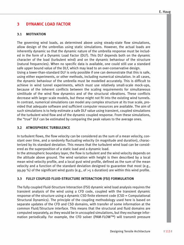
3 DYNAMIC LOAD FACTOR
3.1 MOTIVATION
The governing wind loads, as determined above using steady-state flow simulations,allow design of the umbrellas using static simulations. However, the actual loads areinherently dynamic so that the dynamic nature of the umbrella response must be includ-ed in the form of a Dynamic Load Factor (DLF). This DLF depends both on the dynamiccharacter of the load (turbulent wind) and on the dynamic behaviour of the structure (natural frequencies). When no specific data is available, one could still use a standardsafe upper bound value of the DLF, which may lead to an over-conservative design. Using a lower-than-standard DLF is only possible if one can demonstrate that this is safe,using either experiments, or other methods, including numerical simulation. In all cases,the dynamic behaviour of the umbrella must be modelled accurately. This is difficult toachieve in wind tunnel experiments, which must use relatively small-scale mock-ups,because of the inherent conflicts between the scaling requirements for simultaneoussimilitude of the wind flow dynamics and of the structural vibrations. These conflictsdecrease with larger scale models, but these might not fit into the existing wind tunnels.In contrast, numerical simulations can model any complex structure at its true scale, pro-vided that adequate software and sufficient computer resources are available. The aim ofsuch simulations is to help estimate a safe DLF value using transient, coupled simulationsof the turbulent wind flow and of the dynamic coupled response. From these simulations,the “true” DLF can be estimated by comparing the peak values to the average ones.
3.2 ATMOSPHERIC TURBULENCE
In turbulent flows, the flow velocity can be considered as the sum of a mean velocity, con-stant over time, and a randomly fluctuating velocity (in magnitude and duration), charac-terized by its standard deviation. This means that the turbulent wind load can be consid-ered as the superposition of a static load and a dynamic load. In the atmospheric boundary layer, the flow is turbulent and the wind velocity depends onthe altitude above ground. The wind variation with height is then described by a localmean wind velocity profile, and a local gust wind profile, defined as the sum of the meanvelocity and a function of the standard deviation designed to guarantee that most (e.g.,99,99 %) of the significant wind gusts (e.g., of >5 s duration) are within this wind profile.
3.3 FULLY COUPLED FLUID-STRUCTURE INTERACTION (FSI) FORMULATION
The fully coupled Fluid-Structure Interaction (FSI) dynamic wind load analysis requires thetransient analysis of the wind using a CFD code, coupled with the transient dynamicresponse of the structure using a dynamic CSD finite element code (CSD = ComputationalStructural Dynamics). The principle of the coupling methodology used here is based onseparate updates of the CFD and CSD domains, with transfer of some information at thecommon Fluid/Structure interface. This means that the structural and fluid domains arecomputed separately, as they would be in uncoupled simulations, but they exchange infor-mation periodically. For example, the CFD solver (PAM-FLOW™) will transmit pressure
E. Haug
TensiNet Symposium 2003I 114 I
Numerical Simulations for Wind Load Design of Large Umbrellas
loads to the dynamic CSD solver (PAM-CRASH™), which in turn will send boundary displacements back to the CFD code. This methodology allows the use of different timesteps in the fluid and structural parts for a given simulated physical duration, using sub-cycling. Information is updated at each time step for each solver (by interpolation) so thattransient simulations are easily achieved. This coupling methodology has been develop-ing for several years and has been applied and validated for specific cases like airbagdeployment. In our implementation of this coupling methodology, the information transferred can beinterpolated between the discrete (and different) structural and CFD meshes. This allowsthe use of non-coincident meshes, as best suited for each solver. The CFD solver is able toautomatically regenerate its own mesh, so that the simulation can be performed evenwhen the displacements are very large. The CSD code uses the same mesh in the coupledanalyses. The geometrical model includes the surrounding nearby buildings, so that the wind fluc-tuations generated by these obstacles in their wakes, and by the umbrella itself, can besimulated accurately (at least for the larger turbulence generating structures (comparableto the umbrella size and larger)). Much smaller structures are included in the simulationusing an equivalent turbulence model. In the simulations performed currently, the atmos-pheric turbulence from remote obstacles has been included using the turbulence model.It is planned to simulate more accurately the atmospheric turbulence using a specific sto-chastic inflow condition, where the turbulent fluctuations will be generated artificially atthe inflow boundary of the flow domain, according to the governing local mean and gustwind profiles. As the coupling methodology is inherently transient, a typical simulationhas two phases. The first start-up phase establishes a steady-state response of the windflow around the umbrella in quasi-static equilibrium with the wind pressure field. The convergence to this equilibrium state is accelerated by using some damping in thestructure. In the second phase, the damping is removed and the coupled system is left toevolve freely.
3.4 RESULTS
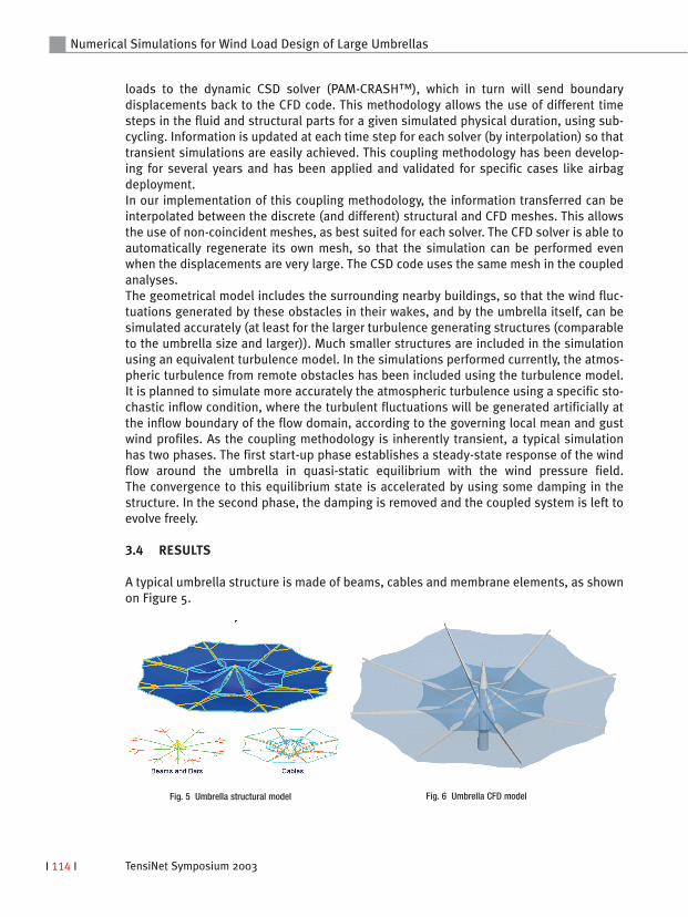
A typical umbrella structure is made of beams, cables and membrane elements, as shownon Figure 5.
Fig. 5 Umbrella structural model Fig. 6 Umbrella CFD model

Designing Tensile Architecture I 115 I
The corresponding CFD geometryis presented on Figure 6.
In a coupled simulation, it isnecessary to define preciselythe location of the informationexchange. In our specific case,this is achieved in the structuralsolver by defining a special typeof pressure load (wind normaland shear surface stresses), andin the flow solver by defining aspecific sub-domain for trans-mittal of the movement of theboundary as provided by thestructural solver. Figure 7 presents snapshots ofthe displacement contours onthe deformed structural modelsof a group of four umbrellas atthree different times. The sur-rounding buildings are not dis-played.
The moment at the base of themast can then be displayed as afunction of time for the fourumbrellas, Figure 8. One clearlyobserves the first start-upphase, up to about 15 s, thenthe second phase with a quasi-“permanent” regime. In thisconfiguration, one umbrella wasmore exposed than the threeothers, and presents significantdynamic amplification. It is also interesting to comparethe results of a fully coupledsimulation with fully flexiblemembrane roofs and masts, tothose of a simplified approach,where the roofs themselves areassumed rigid, and only thecentral masts are held flexible.This latter configuration is iden-tical to the models commonlyused for wind tunnel experi-
E. Haug
Fig. 7 Fully coupled FSI Simulation: Displacement contours and deformedshapes of the umbrella structures at three different times (snapshots)
Fig. 8 Fully coupled FSI Simulation: Moments at the base of the masts as afunction of time
TensiNet Symposium 2003I 116 I
4 PERSPECTIVES
Short of building very large-scale physical models, fully coupled FSI simulations, asdescribed above, appear the only practical way to produce true factors of dynamic ampli-fication of fluctuating wind loads on flexible structures. Currently, these simulations arerelatively expensive in terms of computer cost (CPU), and they require significant time tobe performed. The time period could be reduced by using more powerful computers. Inorder to reduce the required CPU, one could try to use implicit solvers (CFD and CSD)instead of explicit solvers. This would allow the use significantly larger time steps for thecoupled simulations. The modelling of the atmospheric turbulence could also beimproved. As mentioned in §3.3, a new stochastic inflow condition should be developedand tested. Alternatively, one could also proceed in a similar manner to the wind tunnelexperiments: additional obstacles upstream of the test region would generate the addi-tional turbulent fluctuations.
Numerical Simulations for Wind Load Design of Large Umbrellas
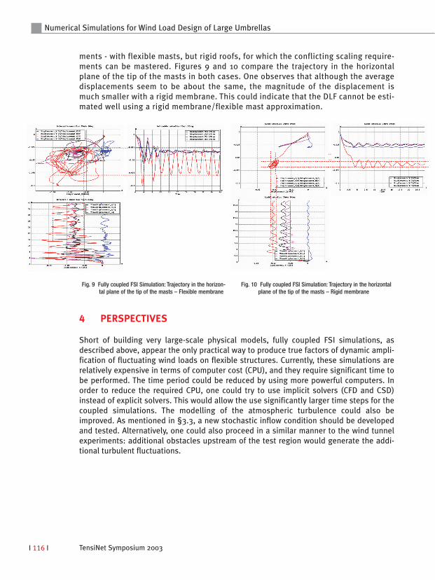
ments - with flexible masts, but rigid roofs, for which the conflicting scaling require-ments can be mastered. Figures 9 and 10 compare the trajectory in the horizontalplane of the tip of the masts in both cases. One observes that although the averagedisplacements seem to be about the same, the magnitude of the displacement ismuch smaller with a rigid membrane. This could indicate that the DLF cannot be esti-mated well using a rigid membrane/flexible mast approximation.
Fig. 9 Fully coupled FSI Simulation: Trajectory in the horizon-tal plane of the tip of the masts – Flexible membrane
Fig. 10 Fully coupled FSI Simulation: Trajectory in the horizontalplane of the tip of the masts – Rigid membrane

Designing Tensile Architecture I 117 I
E. Haug
CONCLUSIONS
A numerical simulation methodology has been applied to the determination of wind loadson large flexible umbrella structures. Simulation results have been compared with successwith experimental results obtained in the wind tunnel on rigid structures. An extension ofthis methodology, based on iterative simulations with a flow and a structural solver,allowed the inclusion of the effects of the membrane deformation on the determination ofgoverning wind loads on large umbrellas. Additionally, a new Fluid-Structure Interactiontechnique has been used to estimate the Dynamic Load Factor. Preliminary results areencouraging and a first important result is that, for the umbrellas, it is probably not pos-sible to neglect membrane deformation. This could lead to a low (unsafe) estimate of theDLF. Future improvements of this FSI technique have also been proposed.
ACKNOWLEDGEMENTS
Experimental wind tunnel results have been provided by the Institute for Hydromechanicsat the University Karlsruhe, Professor Bodo Ruck (http://www.ifh.uni-karlsruhe.de/ifh/science/aerodyn/). Some material was reproduced from the DELITEEuropean CRAFT Project (Contract Nb. BRST.CT98-5166). The umbrella example was elab-orated based on designs by SL Rasch GmbH, Stuttgart, Germany.
REFERENCES
[1] PAM-FLOW™ v2002, Theory Manual, ESI Software S.A., 99, rue des Solets, Silic 112, 94513 Rungis Cedex, France (http://www.esi-group.com)
[2] LISA™ v2000b, Reference Manual, ESI Software S.A., 99, rue des Solets, Silic 112, 94513 Rungis Cedex, France (http://www.esi-group.com)
[3] DELITE: Task 3.2, Static Wind Load Analysis, CRAFT Contract Nb. BRST.CT98-5166, Proposal Nb. BES2-2498.
[4] DELITE: Task 3.4.6, Simulation of Fluid/Structure Interaction, CRAFT Contract Nb.BRST.CT98-5166, Proposal Nb. BES2-2498.


![arXiv:2003.07701v1 [cs.CE] 13 Mar 2020an ad hoc basis. Computational fluid dynamics (CFD) simulations are an attractive tool to comple Computational fluid dynamics (CFD) simulations](https://static.fdocuments.us/doc/165x107/60280adf43604340af3b6dc3/arxiv200307701v1-csce-13-mar-2020-an-ad-hoc-basis-computational-iuid-dynamics.jpg)


