Compressor System Low Maintenance/Self System Low Maintenance/Self Restoring Crash Cushion...
36
Compressor ® System Low Maintenance/Self Restoring Crash Cushion Installation Manual PN 55010 Revision F (05/09/13) 160 Ave. La Pata San Clemente, California 92673 (949) 361-5663 FAX (949) 361-9205 www.traffixdevices.com
-
Upload
truongngoc -
Category
Documents
-
view
226 -
download
3
Transcript of Compressor System Low Maintenance/Self System Low Maintenance/Self Restoring Crash Cushion...

Compressor® System Low Maintenance/Self Restoring
Crash Cushion Installation Manual
PN 55010 Revision F (05/09/13)
160 Ave. La Pata
San Clemente, California 92673
(949) 361-5663
FAX (949) 361-9205
www.traffixdevices.com

160 Ave. La Pata San Clemente, California 92673
(949) 361-5663 FAX (949) 361-9205
www.traffixdevices.com
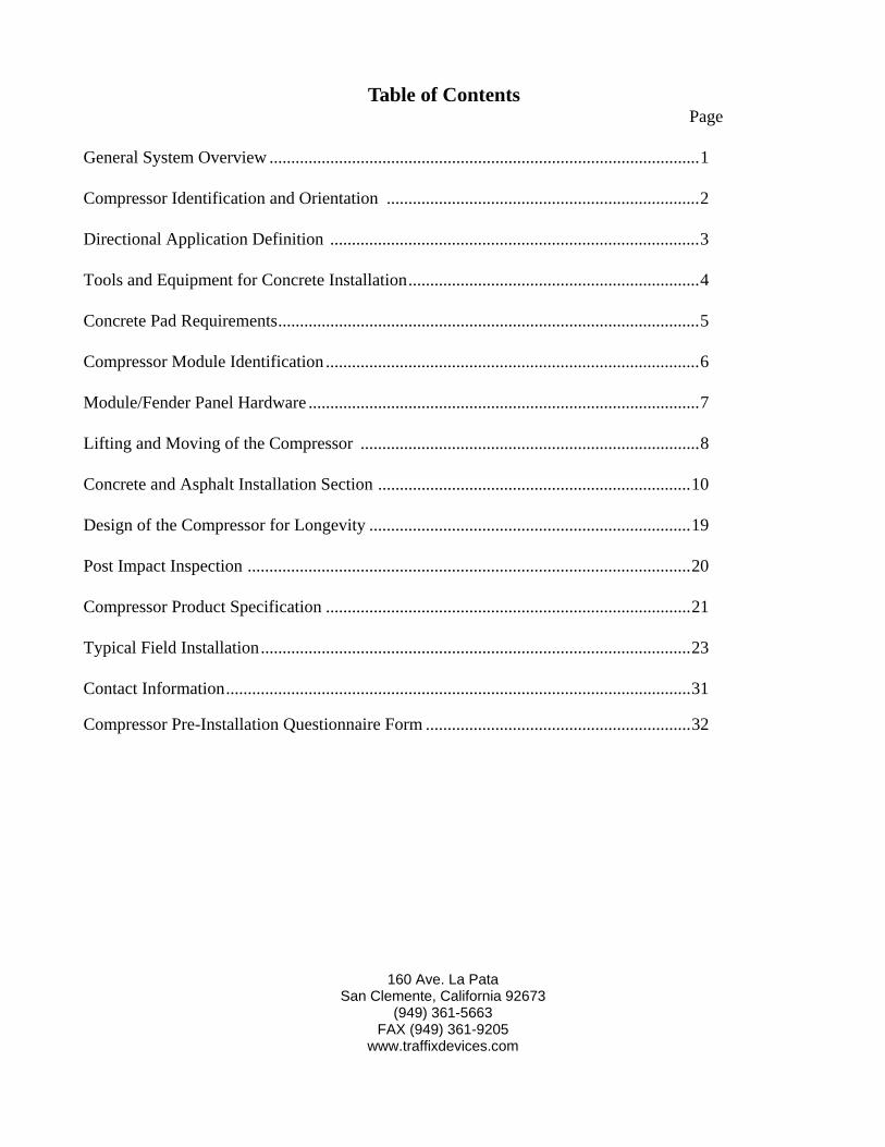
Table of Contents Page
General System Overview ................................................................................................... 1
Compressor Identification and Orientation ........................................................................ 2
Directional Application Definition ..................................................................................... 3
Tools and Equipment for Concrete Installation ................................................................... 4
Concrete Pad Requirements ................................................................................................. 5
Compressor Module Identification ...................................................................................... 6
Module/Fender Panel Hardware .......................................................................................... 7
Lifting and Moving of the Compressor .............................................................................. 8
Concrete and Asphalt Installation Section ........................................................................ 10
Design of the Compressor for Longevity .......................................................................... 19
Post Impact Inspection ...................................................................................................... 20
Compressor Product Specification .................................................................................... 21
Typical Field Installation ................................................................................................... 23
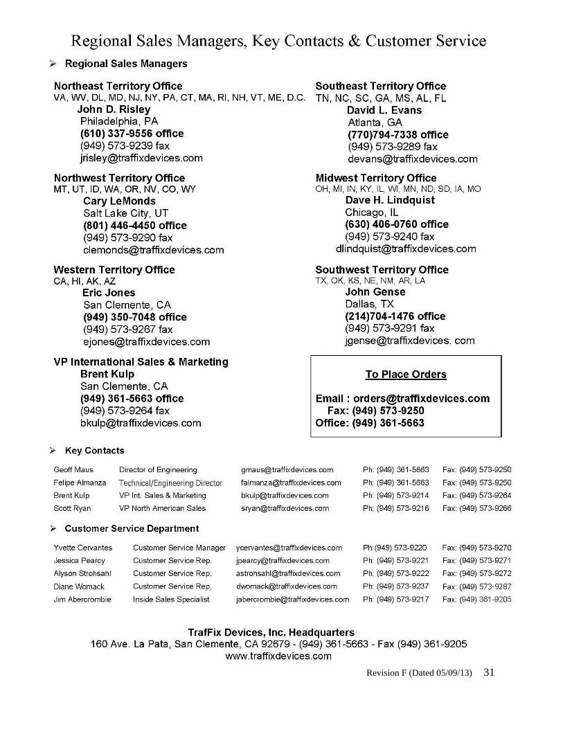
Contact Information ........................................................................................................... 31
Compressor Pre-Installation Questionnaire Form ............................................................. 32

Revision F (Dated 05/09/13) 1
General System Overview
The Compressor® System is a re-directive, uni/bi-directional crash cushion designed to shield immovable objects up to 96 inches. The Compressor System incorporates a self contained Uni-Base™ Platform which does not need to be placed against a rigid object to support itself. The Compressor System consists of six engineered shaped self-restoring plastic modules of varying material thickness and heights to produce the desired energy attenuation characteristics to decelerate an impacting vehicle to meet TL-3 crashworthy requirements of Report NCHRP 350. Attached along the entire length are re-directive fender panels, which slide upon each other when impacted.
Additional Features:
Passed all required NCHRP 350 TL-3 Tests – Accepted for use on the National Highway System – FHWA Product Acceptance Letters CC-95 to CC-95C
Compressor System is a low maintenance/self restoring crash cushion designed to take repeated impacts
Overall length is 21’ – Attenuator Modules/Effective length is 16’6”
Delivered assembled and ready to install – Minimal on-site assembly
Galvanized structural steel Uni-Base™ requires 30 bolts to secure to concrete or as-phalt
All steel components are domestic sourced steel in accordance with Buy America requirements
Compressor’s assembled design combined with the Uni-Base Platform construction makes job site installation fast, easy, and safe – one crew can safely install several units in one day
Compressor’s specially formulated attenuator modules are injection molded from HDPE plastic and are designed to be more efficient when attenuating impact energy in a shorter distance
Attenuator modules are pre-flattened to provide more consistent results after repeated impacts
Compressor’s telescoping steel side-panels re-direct side impacts with minimal damage to attenuator modules or panels
Permanent and Work Zone Applications

Revision F (Dated 05/09/13) 2
Compressor Identification and Orientation
Figure 1 and 2 (or on Pg 40 and 41) identifies the Compressor Systems front and rear orientation for installation. The plastic impact nose bolted to Module #1 orients the front. Module #6 attached to the rear backstop orients to the rear.
Figure 1 (or on pg 40) identifies a Uni-directional configuration which is used in single traffic flow conditions. Figure 2 (or on pg 41) identifies a bi-directional traffic configuration which is used in counter flow conditions utilizing the concrete median barrier (CMB) transition kit.
Figure 1: Uni-Directional Configuration.
Figure 2: Bi-Directional Configuration Shown With Transition Kit Attached to CMB.

Revision F (Dated 05/09/13) 3
Directional Application Definition
The Compressor System is designed for use in either a uni- or bi-directional traffic flow condition as shown in Figures 3 and 4 (or on Pg 42 and 44). A general definition of these applications are seen below with diagrams.
Uni-Directional Application: Uni-directional refers to the flow of traffic in a single direction as seen in Figure 3 (or on Pg 42). In this type of application opposite direction impacts would not be probable.
Bi-directional Application: Bi-directional refers to the flow of traffic in both directions typically referred to as counter flow seen in Figure 4 (or on Page 44). In this type of application the counter flow of traffic will result in both frontal and reverse impacts into the Compressor System. Because reverse impacts may occur, a transition kit, is used to shield the CMB end.
Figure 3: Traffic Flow Application in Single Direction.
Figure 4: Traffic Flow Application in Counter Flow Direction.

Revision F (Dated 05/09/13) 4
Tools and Equipment for Concrete Installation List of tools is a recommendation only and the actual tools required will depend on site conditions for the installation. Personal protective equipment should always be used during Compressor installation. Safety glasses, steel toe boots, hard hat and gloves are recommended as protection devices for the installer’s safety.
Documents
Before installation it is recommended that the complete manufactures manual and drawing package be reviewed for clarity of the installation.
Tools:
Concrete Hole Drilling Tools: (Suggestions Would Be)
-Two Fluted Concrete Drill Bit 1” Dia
-Rebar Cutting Drill Bit 1” Dia
-Rebar Eater or Cutter
-Roto Hammer Drill
-Nylon brush and container of cleaning alcohol for cleaning 1” drilled holes
Drill bits should be capable of drilling to depths of min 6” below grade and be of good quality to drill through 4000 psi concrete.
Additional Tools:
In addition to hole drilling tools, the following is suggested:
-Electrical Generator (5 kW) and Air Compressor (100 psi)
-Torque Wrench 200 ft-lbs min
-Impact Wrench 1/2” Drive
-Sockets 1/2” Drive 3/4”-2” Nut and Bolt Size Shallow and Deep Sockets
-Ratchet and extensions 1/2” Drive
-Wrench Set Open/Box End 3/4”-2” Nut and Bolt Size
-Adjustable Wrench 12”
-Pry/Breaker Bars
-Sledge and Ball Peen Hammers
-Chalk Line
-Concrete Marking Pencil
-Tape Measure
Optional Tools:
Tools that may also be needed: Grinders, Hacksaw, or Torch
The Compressor is delivered assembled and does not require any assembly beyond anchoring to the pad. Cutting of any components on the Compressor is not acceptable and cutting tools should not be used on the Compressor itself.
Revision F (Dated 05/09/13) 5
Concrete Pad Requirements
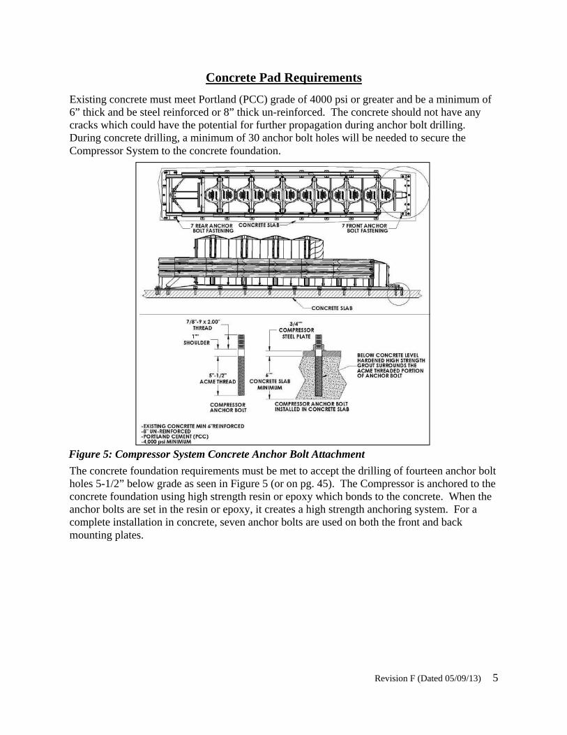
Existing concrete must meet Portland (PCC) grade of 4000 psi or greater and be a minimum of 6” thick and be steel reinforced or 8” thick un-reinforced. The concrete should not have any cracks which could have the potential for further propagation during anchor bolt drilling. During concrete drilling, a minimum of 30 anchor bolt holes will be needed to secure the Compressor System to the concrete foundation.
Figure 5: Compressor System Concrete Anchor Bolt Attachment
The concrete foundation requirements must be met to accept the drilling of fourteen anchor bolt holes 5-1/2” below grade as seen in Figure 5 (or on pg. 45). The Compressor is anchored to the concrete foundation using high strength resin or epoxy which bonds to the concrete. When the anchor bolts are set in the resin or epoxy, it creates a high strength anchoring system. For a complete installation in concrete, seven anchor bolts are used on both the front and back mounting plates.

Revision F (Dated 05/09/13) 6
Compressor Module Identification
The Compressor Module identification sequence is based on a numeric sequence of 1-6. The front Module #1 begins the array and the subsequent Modules are 2, 3, 4, 5, and 6. Hardware diagram Figure 6 (or on pg 46) identifies the complete Module assembly sequence.
Figure 6: Module Identification Sequence with Hardware.
Module Element Types
The Compressor system consist of three configurations.
Modules 1 and 2 Height: 28-1/2” Thickness: 1-1/2”
Module 3 Height: 48” Thickness: 1-1/2”
Module 4, 5, and 6 Height: 48” Thickness: 1-7/8
Figure 7: Module Element Overall Size and Dimensions.
Figure shown without fenders and covers.
Figure shown without covers.
Revision F (Dated 05/09/13) 7
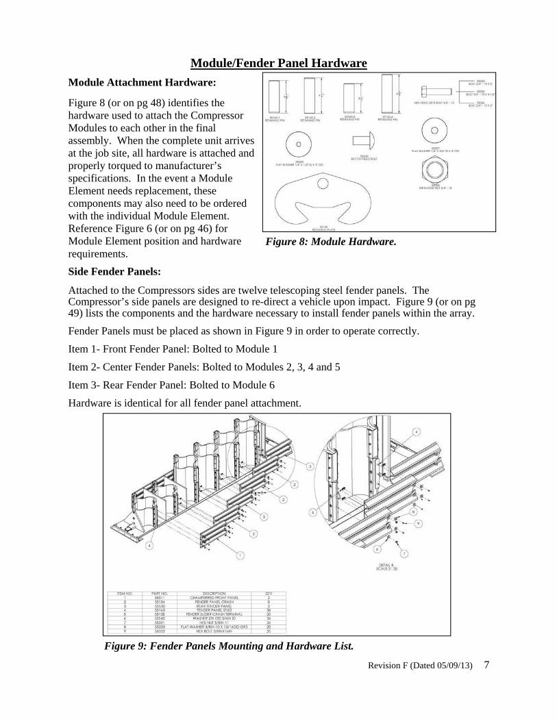
Side Fender Panels:
Attached to the Compressors sides are twelve telescoping steel fender panels. The Compressor’s side panels are designed to re-direct a vehicle upon impact. Figure 9 (or on pg 49) lists the components and the hardware necessary to install fender panels within the array.
Fender Panels must be placed as shown in Figure 9 in order to operate correctly.
Item 1- Front Fender Panel: Bolted to Module 1
Item 2- Center Fender Panels: Bolted to Modules 2, 3, 4 and 5
Item 3- Rear Fender Panel: Bolted to Module 6
Hardware is identical for all fender panel attachment.
Module Attachment Hardware:
Figure 8 (or on pg 48) identifies the hardware used to attach the Compressor Modules to each other in the final assembly. When the complete unit arrives at the job site, all hardware is attached and properly torqued to manufacturer’s specifications. In the event a Module Element needs replacement, these components may also need to be ordered with the individual Module Element. Reference Figure 6 (or on pg 46) for Module Element position and hardware requirements.
Figure 8: Module Hardware.
Figure 9: Fender Panels Mounting and Hardware List.
Module/Fender Panel Hardware
Revision F (Dated 05/09/13) 8
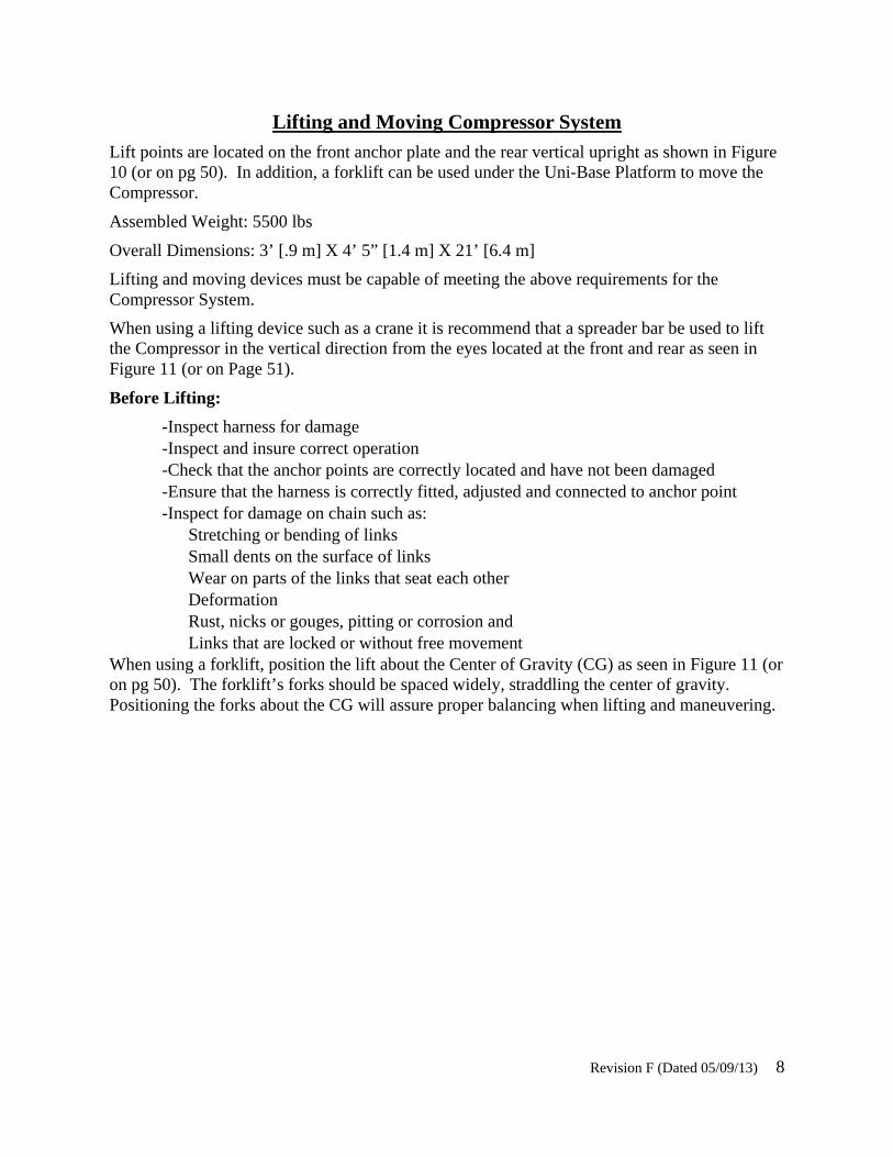
Lifting and Moving Compressor System Lift points are located on the front anchor plate and the rear vertical upright as shown in Figure 10 (or on pg 50). In addition, a forklift can be used under the Uni-Base Platform to move the Compressor.
Assembled Weight: 5500 lbs
Overall Dimensions: 3’ [.9 m] X 4’ 5” [1.4 m] X 21’ [6.4 m]
Lifting and moving devices must be capable of meeting the above requirements for the Compressor System.
When using a lifting device such as a crane it is recommend that a spreader bar be used to lift the Compressor in the vertical direction from the eyes located at the front and rear as seen in Figure 11 (or on Page 51).
Before Lifting:
-Inspect harness for damage -Inspect and insure correct operation -Check that the anchor points are correctly located and have not been damaged -Ensure that the harness is correctly fitted, adjusted and connected to anchor point -Inspect for damage on chain such as:
Stretching or bending of links Small dents on the surface of links Wear on parts of the links that seat each other Deformation Rust, nicks or gouges, pitting or corrosion and Links that are locked or without free movement
When using a forklift, position the lift about the Center of Gravity (CG) as seen in Figure 11 (or on pg 50). The forklift’s forks should be spaced widely, straddling the center of gravity. Positioning the forks about the CG will assure proper balancing when lifting and maneuvering.

Revision F (Dated 05/09/13) 9
Figure 11: Compressor System Lifted Using Spreader Bar at Angle from Lifting Points.
Figure 10: Compressor System Lifted at Angle from Lifting Points.

Revision F (Dated 05/09/13) 10
Concrete and Asphalt
Installations

Revision F (Dated 05/09/13) 11
The Compressor system is a self-contained device which does not need to be placed directly against an object for support. The Uni-Base Platform design contains its own support system utilizing a vertical and rear angle support structure. This self-contained Uni-Base Platform de-sign is used for concrete and asphalt pad installation.
For concrete installation thirty (30) anchor bolts are required. Concrete anchor bolts are 7/8” diameter, 8-1/2” length and require a minimum embedment depth of 5-1/2”.
For asphalt installation thirty (30) anchor bolts are required. Asphalt anchor bolts are 7/8” di-ameter, 16” long and require a minimum embedment depth of 14”.
The Compressor system can be placed directly onto the foundation pad as a completely assem-bled unit as received from the factory. The anchor bolt bore holes can be drilled into the foun-dation using the Uni-Base anchor points as a template. Upon completion of boring the anchor bolt holes the adhesive system can be dispensed into each hole. Then the anchor with the nut and washer thread at the end can be inserted into the bore holes. The anchor nut should not have any exposed thread above the nut. Torque the anchor bolt nuts only after the adhesive has set. Follow adhesive manufactures set times vary under various environmental conditions.
Installation Guide
Figure 12: Compressor System Anchor Points.
Pad Type Anchor Bolt Min Embedment Depth
6” Reinforced Concrete Dia 7/8” X 7-1/2” 5-1/2”
8” Reinforced Concrete Dia 7/8” X 7-1/2” 5-1/2”
3” Asphalt Over 3” Concrete Dia 7/8” X 16” 14”
6” Asphalt Over 6” Concrete Dia 7/8” X 16 14”
6” Asphalt Over 6” Compact Subbase Dia 7/8” X 16” 14”
6” Asphalt Over 8” Compact Subbase Dia 7/8” X 16” 14”

Revision F (Dated 05/09/13) 12
Installation Section
Anchor Bolt Concrete Installation
The Compressor System is a self-contained device which does not need to be placed directly against any object for support. The Uni-Base Platform design contains its own support system utilizing a vertical and rear angle support structure.
To attach the Compressor System to the concrete foundation, thirty (30) 7/8” anchor bolts 8-1/2” in length are used at the front, rear and sides as seen in Figure 13.
The Compressor is designed to be positioned in front of hazardous objects. The installation site is based on a pre-approved site plan from state or local authorities. Conditions which should be approved can include but not limited to bi-directional use, center or offset position relative to the fixed object, or distance from the fixed object. Each installation can be unique and local regulations should always be followed to assure proper installation. For assis-tances on installation or assembly of the Compressor System, the manufacture can be contacted.
The Uni-Base Platform anchoring mounting plate holes can be used as a drill template for the anchor bolt holes in the concrete.
Figure 13: Anchor Bolt Installation

Revision F (Dated 05/09/13) 13
New Concrete Installation
New concrete installation must meet Portland (PCC) grade of 4000 psi or greater and be a minimum of 6” thick with steel reinforced rebar or 8” thick un-reinforced. During concrete drilling, thirty (30) anchor bolt holes will be needed to secure the Compressor System to the concrete foundation.
The concrete foundation requirements must be met to accept the drilling of thirty (30) anchor bolt holes 5-1/2” below grade as seen in Figure 13 and 14.
Anchor bolt holes are filled with a high strength resin or epoxy to secure bonding between the anchor bolt and the concrete.
Minimum resin or epoxy requirements:
Compressive Strength: (ASTM D695) , 17,000 PSI
Tensile Strength: (ASTM D638), 5,510 PSI
Tensile Modules: (ASTM D638), 1.14 x 10⁶ PSI
Flexural Modulus: (ASTM D790), 1.06 x 10⁶ PSI
Figure 14: Concrete Pad Layout

Revision F (Dated 05/09/13) 14

Revision F (Dated 05/09/13) 15

Revision F (Dated 05/09/13) 16
Installation Section
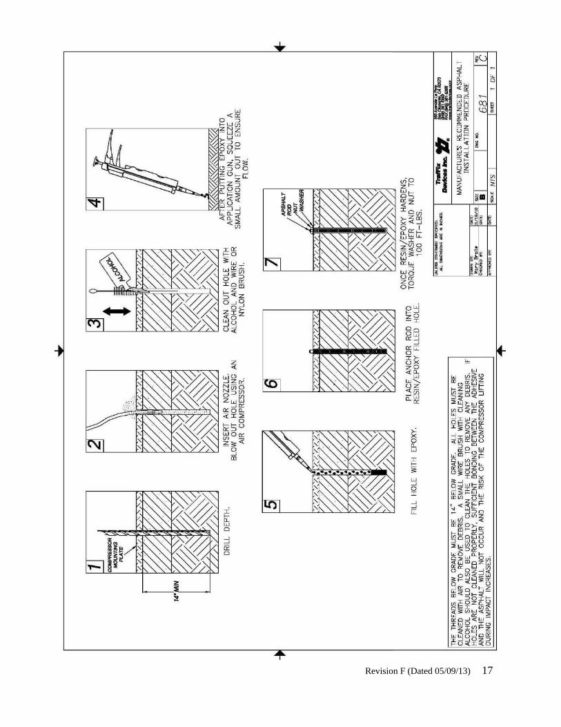
Anchor Bolt Asphalt Installation
The Compressor System is a self contained device which does not need to be placed directly against any object for support. The Uni-Base Platform design contains its own support system utilizing a vertical and rear angle support structure.
To attach the Compressor System to the asphalt pad, thirty (30) 7/8” anchor rods 16” in length are used at the front, sides, and rear as seen in Figure 15 (or on pg. 46).
The Compressor is designed to be positioned in front of a hazardous objects. The installation site is based on a pre-approved site plan from state or local authorities. Conditions which should be approved and can include but not limited to bi-directional use, center or offset position relative to CMB position, or distance from the CMB. Each installation can be unique and local regulations should always be followed to assure proper installation. For assistances on installation or assembly of the Compressor System, the manufacture can be contacted.
The Uni-Base Platform anchoring mounting plate holes can be used as a drill template for the anchor bolt holes in the asphalt.
Figure 15: Anchor Bolt Installation
Revision F (Dated 05/09/13) 17

Revision F (Dated 05/09/13) 18

Revision F (Dated 05/09/13) 19
Design of the Compressor for Longevity
All steel parts are hot dipped galvanized zinc plated to reduce corrosion from developing in harsh environments. When properly installed and maintained, the steel components are expected to have a 10+ year lifespan.
The plastic Module Elements which attenuate the energy of an impacting vehicle contain a blend of Ultra Violet (UV) inhibitors to minimize UV degradation when exposed to sunlight. When properly installed and maintained, module life expectancy, unless reduced by severe impact damage, is expected to have an 8 - 10 year lifespan.
Warranty
TrafFix Devices, Inc. warrants the design, material and workmanship of our products for a period of twelve months (12) to be free of any manufacturing defects.
Exemptions to this general warranty include but are not limited to: “wear items”, deterioration or fatigue from ordinary wear and tear, impacts and other abuse occurring within the warranty period.

Revision F (Dated 05/09/13) 20
Post Impact Inspection Check List 1) Clean and remove debris from Compressor:
2) Inspect for complete rebound of attenuator:
3) Inspect fender panels:
-Check for damage or distortion to the fender panels
-Check that all attachment hardware is in place, secure and undamaged
4) Inspect attenuator anchoring:
-Check anchor bolts for damage
-Check anchor bolts for proper torque
-Check concrete pad for damage or cracking
5) Inspect plastic module elements:
-Check the modules for cracks, gouges, distortion
-Verify the modules are positioned properly on the dovetail of the base
6) Inspect condition of Uni-base platform:
-Check deck surface for damage
-Check dovetail rail for damage
-Check backstop for damage
7) Inspect all fasteners and hardware on the Compressor:
-Check module bolts
-Check fender panel hardware
-Check retaining plate hardware
8) Inspect cover:
-Check for tears and damage
-Check attachment points are secure
-Check all shock cords are in place, and secure
9) Inspect Transition:
-Check for bent or damaged components
-Check for damaged or loose fasteners
-Check for secure attachment to protected element
-Check / adjust tension of fender panel turnbuckles

Revision F (Dated 05/09/13) 21
Compressor System Product Specification
I GENERAL
The Compressor Fixed Attenuator shall be produced and manufactured solely by TrafFix Devices, Inc. (TDI)
Corporate Office, Manufacturing, and Distribution Center, San Clemente, California
II SYSTEM DESCRIPTION
The Compressor is a narrow crash cushion with re-directive non-gating attributes made of energy absorbing plastic module array elements, designed to recover to near its original shape after being impacted. The overall dimension of the Compressor shall be approximately 48.66” (1.119 m) wide x 53.5” (1.36 m) high x 255.25” (6.48 m) long.
III INDIVIDUAL COMPONENT DESCRIPTION
The energy attenuating Module Elements shall have a convex center section and concave outer ends which, when bolted together at the outer edges, form an element which is deformed flat on impact. The thickness of the Module Element units shall vary across the width and not remain constant. The thickness of the elements shall decrease from the outer edge at the center to a minimum near the intersection of the convex and concave curvatures. The Module Elements centerline thickness shall vary between 1-1/2” to 2”. All Module Elements shall be made of high density polyethylene (HDPE) and shall be black in color.
Individual Module Elements overall dimensions shall be approximately 33” x 34-1/2” x 24” and 33” x 34-1/2” x 48”.
Compressor Attenuators shall utilize six assembled Module Elements to make the complete energy attenuating crash cushion array. Each Module Element contains two individual halves which are bolted together at the outer ends and form the complete Module Element assembly.
The Compressor shall have fender panels, which telescope and slide on top of each other when impacted. The fender panels shall bolt directly to each module element. The panels shall be made of high tensile strength steel that provides a high level of impact resistance through a Thrie-beam design, and have a minimum strength of 80 ksi. Each fender panel shall contain two flat valley shapes which contain a full length slot in each flat valley section of the panel which slide within each other through sliding fender panel buttons. The overall dimensions of the individual corrugated fender panels shall be 6” x 20” x 36”. When bolted to the complete assembly twelve individual panels shall be used six per side and have overall dimensions of 6” x 20” x 255”.
The Compressor’s energy absorbing Module Elements shall have a wedged shaped dovetail molded into the bottom of each element, which engages the mating steel dovetail which shall be welded and formed onto the steel base plate referred to as the “Uni-Base Platform”. The function of the mating steel dovetail is to provide structural strength during impacts that contain lateral and vertical components.

Revision F (Dated 05/09/13) 22
The Uni-Base Platform structure consists of formed steel plates, which form a “box” section to a vertical rising dovetail running the full longitudinal distance The Uni-Base Platform shall provide mounting for a rear vertical support back-up and diagonal support brace. The Uni-Base Platform shall be capable of being installed in concrete using a minimum of fourteen high strength anchor bolts. Anchor bolts shall be installed through the Uni-Base Platform’s front and rear anchor mounting plates which contain seven anchor bolt holes per end.
All steel components shall be domestically produced steel meeting the standards of ASTM A-36, A500, and A572. All metal work shall contain corrosive resistant finishes. Welding shall be done per good industry and commercial practice.
IV Performance Testing Specifications
The Compressor shall be tested and performance results shall act as a re-directive, non-gating crash cushion meeting the acceptable pass test criteria as specified in the National Cooperative Highway Research Project, Report 350.
All Compressor testing shall be of Test Level 3 (TL-3), at an impact speed of 100 kph (62 mph) criteria.
V Installation and Maintenance
Installation and maintenance shall be based on the directions of TrafFix Devices, Inc. contained in the Installation and Maintenance Manual produced by the Engineering Department.

Revision F (Dated 05/09/13) 23
Typical
Field
Installations
160 Ave. La Pata San Clemente, California 92673
(949) 361-5663 FAX (949) 361-9205
www.traffixdevices.com
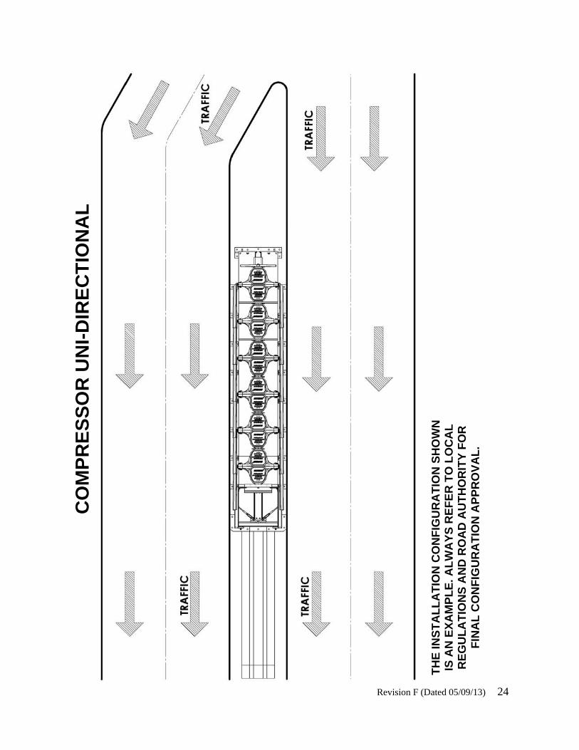
Revision F (Dated 05/09/13) 24
CO
MP
RE
SS
OR
UN
I-D
IRE
CT
ION
AL
TH
E IN
ST
AL
LA
TIO
N C
ON
FIG
UR
AT
ION
SH
OW
N
IS A
N E
XA
MP
LE
. AL
WA
YS
RE
FE
R T
O L
OC
AL
R
EG
UL
AT
ION
S A
ND
RO
AD
AU
TH
OR
ITY
FO
R
FIN
AL
CO
NF
IGU
RA
TIO
N A
PP
RO
VA
L.
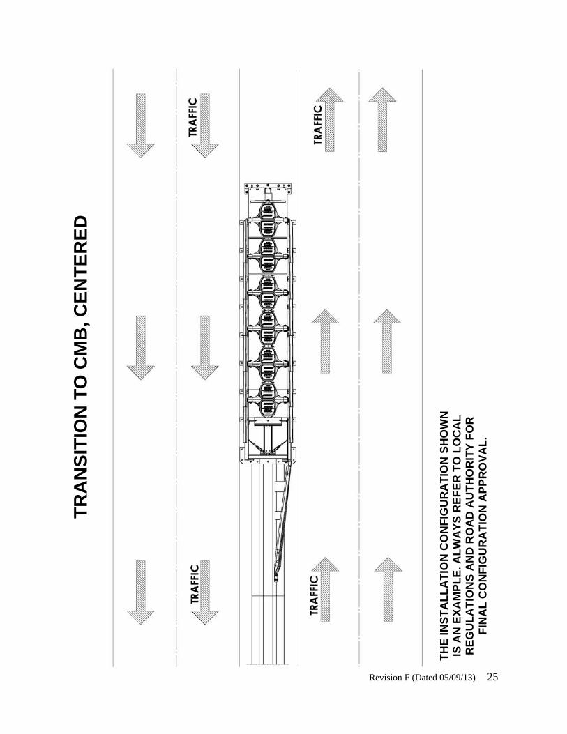
Revision F (Dated 05/09/13) 25
TH
E IN
ST
AL
LA
TIO
N C
ON
FIG
UR
AT
ION
SH
OW
N
IS A
N E
XA
MP
LE
. AL
WA
YS
RE
FE
R T
O L
OC
AL
R
EG
UL
AT
ION
S A
ND
RO
AD
AU
TH
OR
ITY
FO
R
FIN
AL
CO
NF
IGU
RA
TIO
N A
PP
RO
VA
L.
TR
AN
SIT
ION
TO
CM
B, C
EN
TE
RE
D

Revision F (Dated 05/09/13) 26
TH
E IN
ST
AL
LA
TIO
N C
ON
FIG
UR
AT
ION
SH
OW
N
IS A
N E
XA
MP
LE
. AL
WA
YS
RE
FE
R T
O L
OC
AL
R
EG
UL
AT
ION
S A
ND
RO
AD
AU
TH
OR
ITY
FO
R
FIN
AL
CO
NF
IGU
RA
TIO
N A
PP
RO
VA
L.
TR
AN
SIT
ION
TO
CM
B, O
FF
SE
T

Revision F (Dated 05/09/13) 27
TH
E IN
ST
AL
LA
TIO
N C
ON
FIG
UR
AT
ION
SH
OW
N
IS A
N E
XA
MP
LE
. AL
WA
YS
RE
FE
R T
O L
OC
AL
R
EG
UL
AT
ION
S A
ND
RO
AD
AU
TH
OR
ITY
FO
R
FIN
AL
CO
NF
IGU
RA
TIO
N A
PP
RO
VA
L.
TR
AN
SIT
ION
TO
CM
B, T
WO
SID
ED

Revision F (Dated 05/09/13) 28
TH
E IN
ST
AL
LA
TIO
N C
ON
FIG
UR
AT
ION
SH
OW
N
IS A
N E
XA
MP
LE
. AL
WA
YS
RE
FE
R T
O L
OC
AL
R
EG
UL
AT
ION
S A
ND
RO
AD
AU
TH
OR
ITY
FO
R
FIN
AL
CO
NF
IGU
RA
TIO
N A
PP
RO
VA
L.
TR
AN
SIT
ION
TO
W B
EA
M

Revision F (Dated 05/09/13) 29
TH
E IN
ST
AL
LA
TIO
N C
ON
FIG
UR
AT
ION
SH
OW
N
IS A
N E
XA
MP
LE
. AL
WA
YS
RE
FE
R T
O L
OC
AL
R
EG
UL
AT
ION
S A
ND
RO
AD
AU
TH
OR
ITY
FO
R
FIN
AL
CO
NF
IGU
RA
TIO
N A
PP
RO
VA
L.
TR
AN
SIT
ION
TO
TH
RIE
BE
AM

Revision F (Dated 05/09/13) 30
TR
AN
SIT
ION
TO
CO
NC
RE
TE
BL
OC
K
TH
E IN
ST
AL
LA
TIO
N C
ON
FIG
UR
AT
ION
SH
OW
N
IS A
N E
XA
MP
LE
. AL
WA
YS
RE
FE
R T
O L
OC
AL
R
EG
UL
AT
ION
S A
ND
RO
AD
AU
TH
OR
ITY
FO
R
FIN
AL
CO
NF
IGU
RA
TIO
N A
PP
RO
VA
L.
Revision F (Dated 05/09/13) 31


160 Ave. La Pata San Clemente, California 92673 (949) 361-5663 FAX (949) 361-9205
www.traffixdevices.com
Distributed By: