COMPRESSIVE CHARACTERISTICS OF THE LABRUM · the compressive characteristics of the glenod labrum...
110
THE COMPRESSIVE CHARACTERISTICS OF THE GLENOD LABRUM by JASON CAREY .4 thesis submitted to the Department of Mechanical Engineering in conformity with requirements for the degree of Master of Science (Engineering) Queen's University Kingston. Ontario. Canada January. 1998 Copyright O Jason Carey, 1998
Transcript of COMPRESSIVE CHARACTERISTICS OF THE LABRUM · the compressive characteristics of the glenod labrum...
THE COMPRESSIVE CHARACTERISTICS OF THE GLENOD
LABRUM
by
JASON CAREY
.4 thesis submitted to the Department of Mechanical Engineering
in conformity with requirements for
the degree of Master of Science (Engineering)
Queen's University
Kingston. Ontario. Canada
January. 1998
Copyright O Jason Carey, 1998
National tibrary Bibliothèque nationale du Canada
Acquisitions and Acquisitions et Bibliographie Services services bibliographiques
395 Wellington Street 395. rue Wellington Ottawa ON K I A ON4 Ottawa ON K I A ON4 canada Canada
The author has granted a non- L'auteur a accordé une licence non exclusive licence dowing the exclusive permettant à la National Libraxy of Canada to Bibliothèque nationale du Canada de reproduce, loan, distribute or seli reproduire, prêter, distibuer ou copies of this thesis in microforni, vendre des copies de cette thèse sous paper or electronic formats. la fome de microfiche/film, de
reproduction sur papier ou sur format électronique.
The author retains ownership of the L'auteur conserve la propriété du copyright in this thesis. Neither the droit d'auteur qui protège cette thèse. thesis nor substantial extracts fiom it Ni la thèse ni des extraits substantiels may be printed or othewise de celle-ci ne doivent être imprimés reproduced without the author's ou autrement reproduits sans son permission. autorisation.
Abstract
The labrurn is an extension of the glenoid articular cartilage that helps retain the
humeral head in the glenoid fossa. The superior portion is a thick soft tissue with a
triangular cross sectional are% comparable to knee meniscus, while the inferior portion is
a thin and flatter cartilaginous tissue comparable to articular cartilage.
The objective of this research was to compare the compressive load versus
displacement responses of the glenoid labrum using rapid indentation and obtain the
stiffness and modulus of the tissue. The compressive testing procedure was a novel
method of testing sofi tissue in situ. Stiffness findings validated the testing procedure by
showing repeatability and appropriate similarity.
Six embalmed and nearly intact labra were tested in six morphologically different
sections delimited by other researchers as being susceptible to different injuries. Each
section was indenred at three sites. Site results were averaged and compared between
labra. Similar sections were averaged among the different labra.
Testing assumed an elastic mode1 and examined the linear regions of the load
versus displacement curves for the labral and cartilaginous tissues. Results of the
indentation testing dernonstrated large differences in the stiffness and modulus between
the superior and inferior sections of the glenoid labmm.
The stiffness results showed some simiiarities within sections and confirmed the
variability between various portions of the tissue.
The modulus was defined as the stress applied to the tissue by the indentor
divided by the ratio of displacement and the tissue thickness ( e . : Stress/
[displacernent/thickness]). The labral modulus ranged from 0.1 1 0.16 to 0.4 1 * 0.32
MPa. As for the cartilage. the modulus ranged fkom 1.65 0.78 to 4.82 2.93 MPa.
The modulus results for the labrurn agreed with findings of Joshi (1995) for the
stifiess of human meniscus (0.205 MPa). The infenor section. which Cooper (1992)
believed to be structurally stiffer. was actually the least stiff as a material. Although to
gross observations this section appeared to be the stiffest, the mechanical properties
showed otherwise. This lead to believe that the iderior portion only seemed stiffer
because it was a thinner tissue. This could imply that the lower section is less important
for load bearing.
Results fiorn the second linear portion of the data were in the range of the
findings by Xiaowei (1995) (2 m a ) and Mow (1980) (2MPa) and Rasanen's (1996)
(2.49-0.71 MPa) for articular cartilage. Using actual cartilage thickness values found by
previous studies, the calculated cartilage moduli ranged from 1.29 to 2.00 MPa. These
results are comparable to the previous studies.
Specimen morphology findings agreed with most of the results from previous
studies. It was confikmed that the labmm added 5mm to the anterior posterior depth of
the glenoid fossa as per Howell and Galinat (1 988). However, it did not agree with their
finding stating that the superior inferior depth was increased by 9mm. Gross observation
of the specimens confirmed the larger occurrence of tissue damage in the superior portion
of the labrum. Large differences were found between the dominant and non-dominant
arrn of each cadaver. However, these differences were less than those found between
cadavers.
Acknowledgments
In the past 16 months. many people have been directly or indirectly involved in
the production of this thesis. Al1 of which permitted it to be complete. My time at
Queen's University would not have been the same without you. 1 will always keep fond
mernories of you all.
I would like to thank my thesis supervisor Dr. Carolyn Small. Her patience.
guidance and help with my project were nothing short of remarkable. She took a great
risk by leaving me approach this work mostly in my own way. 1 greatly appreciate it.
She showed me the real meaning of time management. a ski11 very little people master as
well as her.
1 would also like to thank Dr. Dave Pichora, who provided me with insight and
guidance on the medical and anatornical aspects of this project. To Dr. Tim Bryant.
thank you for your so different views on things and guidance with my work.
Without the help of Dave Siu, Gerry Saunders and Lee Watkins at the CMG and
Ailan iMcPhail and Paul Green €rom the department. my thesis could not have been done
so rapidIy. Your technical advice and assistance was instrumental to the realization of
this work.
Many thanks to the following people, Carolyn Anglin, Steve Ferguson. Egil
Naesguthe, Jeff Cassin, and Radovan Zdero who provided me with technical information.
Judy Tse for her help with the cadaver dissections and the pictures. To Wayne Lyons and
Rick Hunt. from the Anatomy Depanment. for helping with the cadavers and for the
insight on proper dissection.
1 rnust thank Suzan Korsmit. Marc Richard and Aaron Dellah for fùrther revisions
on my thesis and for their fiiendship.
1 would Iike to thank the people who have helped me through the challenges of
life with their friendship. First of al1 Patricia McAllister. 1 cannot express in words how
much i owe you for the support. assistance. guidance with school and health tolerance
and friendship during the past year. 1 really could not have done it without you. Thank
you!
To rny always present fnend Oren Tirosh who's outlook on life was a brearh of
fresh air and an antidepressant. Thank you to Gordon McAiary. Jamie Wentzell and
Dave Kirby for al1 the great tirnes.
En avant dernier lieux. je voudrais remercier les "gars" d'Ottawa: Luc. Marc et
Vincent. Votre amitier et fratemiter, a toujours été une source de joie. de rire et de
support.
Finalement. je voudrais remercier mes parents Arlette et Bnan. Leur suppon et
amour inconditionel mon permis de me rendre jusqu'ici. Ceci est pour vous!
To those 1 have forgotten or overlooked. I thank you. You were all important in
the completion of this thesis.
Table of Contents
Page
Abstract ............-.. ..... . ..-.............. . . ........................................... . . .-.-.. . -...........--. .-.-.. .. -. . .... .. i
. . - Acknowledgments . . . . . . . . . . . . . . . . . . . . . . . . . . . . . . . . . . . . . . . . . . . . . . . . . . . . . . . . . . . . . . . . . . - . -. . . . . . . . . . - - -. . . . . . . . . . -. . . . . . . . . . . . - 1 1 1
Table of Contents ...... . . ... ..... .... . ...... .......... .................................. -.. ... .-... ..-. .... ... - . .--.. . . .. . . - - v
. . . List of Fisures .. . . . . . . . . . . . . . . . . . . . . . . . . . . . . . . . . . . . . . . . . . . . . . . . . . . . . . . . . . . . . . . . . . . . . . . . . . . . . . . . . . . . . . .- - -. . . . . . . . . . . . . . - . -. . vi I I
List of Tables .........................,.......-...-.--..---.-.........-..----..----..--.......-....-...................y
Glossary . ... . ........ . ..... ....... ...... ... ...... .......... . ................................... . . .. . . .... . . . ... . . .. . , . . . .. . . . .. . . si
Chapter 1 : Introduction .................................................................................................... 1
. - Chapter 2: Cntical review of literature ........................................................... .... ..........--.. 4
2.1 General anatomy of the shoulder complex ............................ ... ........ .... ...... .. ... .. ... . .-!
2 . L . 1 Bones of the shoulder complex .......................................... ............ ........... .. ....- 5
2.2 Xnatomy of the labmm .... ... ............ .... .......................................................... 7
2.2.1 Labral morp hology . . . .. . . .. . . . . ....... ..... ..... .. ..... ... . . ....... . . . ... . . . . . . . . . . .. . . . .. . . . . .. . . . . . . . . . . . - 7
2.2.2 Labmm microstructure and material properties . . . . . . . . . . . . . . . . . . . . . . . . . . . . . . . . . . . . . . . . . . . . . . . 9
3.3 Labral injuries ....... . .... .... . .......... .. .... . .... ................. . ........ . .. .. ....... . . . . . ... . . .. . . . .. . . . . . . . . 1 1
7.4 Glenohumeral joint stability mechanisms .. . . . . . .. . .. . . . . . . .. . . . . . . . . . . . . . . . . . . . . . . . . . . . . . . . . . . . . . . . . 14
2.4.1 Dynarnic stabilizers . . . . . . . . . .. . . . . . . .. . . ... . . . . . .. .. . .. .... . . . . . . . . . . - . . . . . . . . . . . . . . . . . . . . . . . . . . . . . . 1 5
. . 2.4.2 Static stabilizers ...... .... . .... ... - ... . . . . . . . . . . . . . . . . . . . . . . . . . 16
2.4.3 Role of the labmm in stabilizing the glenohumeral joint ................................ 18
7'3 2.5 Review of different testing procedures . .... . ........ ... ..... .... . . . . ... ... . . . . . .... . . .. . .. . . . . . . . . . . .. --
2.6 Mechanical testing performed on the labrum ........................................... . ....... .... 24
2.7 Material properties and models. .. . . . .. . . . . . ... . . .. . . . . ..... . . . . . .. . . . . . . . . . . . . . . . . . . . . . . . . . . . . . . . . . . . . . . . .3
2.8 Similar tissues: .................................................................................................... 27
2.9 Bone . cartiiaginous and meniscal tissues testing and propenies ........................... 37
7.10 Thesis objectives ............................................................................................... 30
Chapter 3 : Methodolo_ey ................................................................................................ 3 1
3 . 1 Introduction ......................................................................................................... 31
3.3 lnstmmentation .................................................................................................. 1
3 - 3 Specimen collection and preparation ................................................................... 34
* * 3 . J. 1 Specimen collection ...................................................................................... - 3 4
3 . 3 2 Labra sectioning ........................................................................................... - 3 6
. . . * * 7 3 . J . 2 Preconditron~ng ............................................................................................ -36
3.4 Expenmental protocol ...................................................................................... 3 7
3.5 .An alysis ............................................................................................................. 39
3.5.1 Data analysis ........................ .. ....................................................................... 39
3.5.2 Enor analysis ............................................................................................... -44
3 3.3 Statistical analysis ...........................................................................
Chapter 4: Results ..................................... ... ....................................................
4 . I Sampie Information ...............................................................................
4.1.1 Specimen Dimensions .....................................................................
4.1.2 Pre-testing Damage Assessrnent ......................................................
4.3 Indentation Test Results ...................................................................................... 50
4.2.1 Sample Raw Data ............................................................................. .. ........... j I
4.2.2 Stiffness results fi-om the three tests of each section ................................. j 4
4.2.3 Section Averages ...................................................................................... - 6 5
42.4 Statistical Analysis ....................................................................................... -6s
4-7-5 Error Analysis ............................................................................................... 69
Chapter 5: Discussion ................................................................................................. 7 2
5.1 Introduction ......................................................................................................... 72
5.2 Specimen dimensions .................... .. .................................................................... 73
5.3 Specimen observable injuries .............................................................................. 75
5.4 Stiffness results ................................................................................................... 76
5 - 5 Modulus results ................................................................................................... 76
5.5.1 Labrum results .............................................................................................. -77
5.5.2 Cartila_ee results ............................................................................................ -7s
5.5 -3 Averaged labrum and cartilage results ........................................................... 75
5.6 Labrurn's role in the shoulder ............................................................................... 79
5.7 Cornparison of the cartilage tindinçs to previous studies ...................................... SO
5.8 Effect of compressive response variations on possible injury occurrence . . . . . . . . . . S I
5.9 Error anal ysis ...................................................................................................... S I
Chapter 6 : Surnmary ...................................................................................................... S3
6.1 Synopsis .............................................................................................................. 83
6.2 Conclusions ........................................................................................................ -84
6.3 Recommendations ............................................................................................... 86
References .................................................................................................................... -87
Appendix 1 : Hank's Solution composition for 10L of water ........................................... 96
Vita ............................................................................................................................... 97
List of Figures Page
Figure 1 : Bones of the shoulder complex ........................................................................ 5
Fisure 2: Normal labrum ......................... ... ............................................................ 7
Figure 3: Reference axis for the labrum ..................................................... .... .................. 8
Figure 4: Labrai shapes .................................................................................................... 9
Figure 5 : Labrum collagen structure .............................................................................. I O
Figure 6: Labrum 6 divisions ............................................. .. 1 1
Figure 7: Divisions used in Study .................................................................................. Il
Figure 8: Capsular ligaments ......................................................................................... 18
Figure 9: The average maximum translating force resisted in each direction by the
humeral head into the glenoid concavity with a 50N load with (A) and without (B)
the labrum .............................................................................................................. 20
Figure 1 O: Tensiie strength of the labrum attachrnent ....... ..... . ... ........................ 31
Figure 1 1 : Instron and Indentor ................................. ,. ................. 31
Figure 12: Computer and Oscilloscope .......................................................................... 32
Figure 13 : Instrumentation Schematics ....................... ..... .............................................. 3 3
Figure 14: Labrum sectioning ........................................................................................ 26
Figure 15 : Representative data ...................................................................................... - 4 0
Figure 16: Indentor-tissue contacts encountered during testing ..................................... - 4 0
Figure 17: Force versus displacernent data .................................................................... - 4 3
Figure IS: Tissue Thickness used in calculations .......................................................... -46
Figure 19: Three tests performed on section 4 of specimen #5 right ............................... 5 1
... V l l l
Figure 10: Stress vs . percentage of specimen thickness for the three tests performed on
. section 4 of specimen if, right ................................................................................ 52
Figure 2 1 : Ki for al1 specimen sections .................... .... ............................................. 56
Figure 27: Stiffness results for every section of specimen $1 OL ..................................... 57
Figure 23: Stiffness results for eveq section of specimen # 1OR ..................................... 57
Figure 21: Stiffness results for every section of specimen #9L ....................................... 5s
Figure 25: Stiffness results for every section of specimen #9R ....................................... 58
Figure 26: Stiffness results for every section of specimen #5L ....................................... 59
Figure 27: Stiffness results for every section of specimen #SR ...................................... 59
Figure 25: Elastic modulus for specimen XIOL .............................................................. 60
Figure 29: Elastic modulus for specimen #IOR .............................................................. 60
Figure 30: Elastic modulus for specimen X9L ................................................................ 61
Figure 3 1: Elastic modulus for specimen #9R ................................................................ 61
Figure 32: Elastic modulus for specimen #5L ................................................................ 62
Figure 3 3 : Elastic modulus for specirnen 85R ................................................................ 62
Figure 34: Labmm rnodulus for every section ................................................................ 63
Figure 35 : Cartilage modulus for every section .............................................................. 64
Figure 36: Average labral modulus (EL) and Standard deviation (MPa) per section ........ 63
Figure 3 7: Average cartilage modulus(Ec) and standard deviation (MPa) per section
(3mm thickness) .................................................................................................... 66
Figure 3 8: Comparison of labmm vs . cartilage average rnodulus for each section .......... 67
List of Tables Page
Table 1 : Meniscus and Cartilage Properties ................................................................... 28
............................................................................. Table 7: Human Cartilage Properties 28
Table 3 : Zhu ( 1 994) meniscus and cartilage elastic modulus .......................................... 29
Table 4: Specimen overail sizes ..................................................................................... 46
Table 5 : S pecimen Thickness (see Figure 1 8) ............................................................... 4 6
Table 6: Section Average Thickness ........................................................................... 4 7
................................................................... Table 7: Section damages for all specimens 48
Table 8: Observed damage to labral tissue prior to testing ........................................ 48
........................................................ .................. Table 9: Sample calculation resuits .. 52
Table 10: Labmm resuits 54 ...............................................................................................
Table 1 1 : Cartilage resuits based on a assumed 3mrn thickness ...................................... 5 5
Table 12: Uncenainty calculations for the Labmm ....................................................... 69
Table 13 : Uncenainty calculations for Cartilage ............................................................ 70
Glossary
Abduction: Motion away from the midline of the body.
Adduction: Motion towards the midline of the body.
Anisotropic: A material is categorized as anisotropic when its mechanical propenies
Vary with direction.
Anterior: Depicts the front portion of a body or structure.
Posterior: Depicts the back portion of a body or a stmcture.
Arthroplasty: Refers to a complete or partial replacement of a joint with an anificial
implant.
Arthroscopy: Examination of the interior of a joint.
Biphasic: Substance composed of two distinctive material phases.
Labrum: A sofi tissue surrounding the glenoid fossa.
Stability: For this thesis. a stable joint is defined as a joint. restrained only by the
surrounding anatomical stmcture. that undergoes normal physiological motion under
normal physiological loading. Lazarus (1996) added an important part to shoulder
stability by defining it "as the individual's ability to maintain the humeral head
precisely centered within the humeral joint." Both statements provide a complete
definition.
Subiuxation: Incomplete dislocation of a joint.
Superior: Depicts the upper portion of a body or a structure
Inferior: Depicts the lower portion of a body or a structure.
Viscoehstic: Matenal characterized by viscous and elastic properties.
Chapter 1: Introduction
"Recerit!v, ntterltiori has been drmvrl towards kisiorzs ut the
hiczpital-labral ji~nctiot~. Trrmed SLAP Irsiotz. this lesion begim mperior
to the anterior gkerzoid rzotch. incides the biceps anchor, arzd exterzds flo
the posterior mprrior iabnun. The mecharzism of itvziry is trrzclear, h t
both humeral head compression and biceps tendon traction h m hem
Nnpiicated "
(Grauer J.D, 1 993)
One of the roles of biomechanical engineers. with the assistance of the medical
profession, is to define the mechanics of the human body. In so doing, it is necessary to
analyze the properties of soft tissues. One of such tissues is the glenoid labmm. The
glenoid labrum is a fibrocartilaginous tissue that extends from the glenoid canilage.
The labrum's role in the shoulder complex is still a topic of debate. despite strong
evidence anributing it a large importance in many aspects.
The purpose of this study is to evaluate the compressive characteristics of the
glenoid labrum. It is hypothesized that the superior and inferior ponions of the labmm
will have different propenies because of their different morphology. The superior
portion is a soft tissue that morphologically resembles the knee meniscus. while the
inferior portion when touched appears to be a stiffer material.
The shoulder complex is the support joint for the entire arm. Interconnecting the
thorax and the am, it is an agglomeration of many joints and structures; thus making it
arguably the most elaborate joint structures in the human body.
1
Shoulder biomechanics is an ever-increasing field of research for several reasons-
The aging population requires more appropriate replacement technology to ensure the
mobility of their upper extremities. This portion of the population is subject to
degenerative diseases and osteoarthritis. Also, since physical strength and joint stability
tend to decrease with increasing age. there is a higher risk of injury during daily exercise
and tasks. Therefore. there is a greater need for shoulder arthropiasty capable of
reinforcing the joint and restoring the original motion of the joint while retaining original
component properties.
h o t h e r reason for the importance of shoulder biomechanics is the need for better
rehabilitation methods. Understanding where injuries can occur should simpli fy the work
of physiotherapists.
Since A. S. Blundell Bankart identified Iabrum tears as a cause of shoulder laxity
in 1938, researchers have attempted to understand the role of the labnim in the shoulder
complex. Now, more studies are focusing on the role of labral tears in the early
development of shoulder pathology. The studies performed to date have looked at the
physiological role of the labrum and not specifically to the material's response while
resisting direct compressive loading.
To reduce injuries, the stmctures must be restrained frorn performing dificult
tasks that can be compromising to the sofi tissue. As such. the response of soi? tissues to
compressive forces m u t be determined. Many studies have looked at the propenies of
ligaments, muscles. bones. capsule and tendons of the shoulder joint. Very little
literature could be found documenting the properties of the glenoid labnim. This thesis
will examine the compression response of the glenoid labrum.
Chapter 2 summarizes the basic anatornical background of the shoulder. It is also
a synopsis of the findings of earlier studies and examines the various concepts of tissue
mechanics associared with the labrum. Chapter 3 describes and explains the rationale of
the experimental and analyticai procedures. The results are shown in Chapter 4. Chapter
5 will discuss the significance of the results. Chapter 6 wili be a synopsis of the results
and will set recommendations for continuing work.
Chapter 2: Critical review of literature
This chapter focuses on relating the important background information about the
work at hand. As such. it examines important aspects of the shoulder complex. It will
focus on the glenohumeral joint, since the glenoid labnirn is an intraarticuiar ponion of
this joint. The shoulder and labmm anatorny will be detailed initially as a preamble to
the other sections. This will introduce the role of the labmm as a joint stabilizer and its
natural role in shoulder injuries. Finally, previous work and testing methods on the
labmm and other tissues will be examined.
2. I General anatomy of the shoukler cornplex
The shoulder complex is composed of many structures that resemble cornmon
machines. The simplest mechanical example of the shoulder and a m stmcture is a Crane.
because of their similanties in structure. range of motion and uses. It can also be
described as a suspension bridge due to the large number of ligaments and muscles that
retain it in its socket.
2.1.1 Bones of the shoulder cornplex
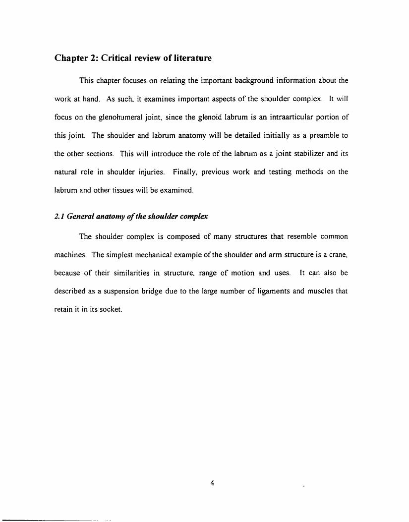
The shoulder complex is composed of four bony stmctures (Figure 1). These are
the scapula, the clavicle. the humetus and the sternum. The scapula is located on the
postenor side of the nb cage and is comrnonly called the 'shoulder blade' (or girdle).
The clavicle is the coliarbone. The humems is the upper a m bone. Finally. the sternum
is the bony iink at the center of the thoracic cage. The sternum is not visible on the
figure. but the clavicle and the sternum join at the sternoclavicular joint. The rib cage.
although not considered one of the bones of the shoulder complex, plays an iniponarit
role in t h e scapularthoracic joint.
Acrornioi
Glenohumeral joint
icic
Figure 1: Boiies of the shoulder complex
The four joints of the shoulder complex are cornposed by the interaction of the
humerus. scapula, clavicle, sternum and rib cage. Two types of joints are foiind in the
shoulder complex: three synovial joints and one fibrous joint. The glenohumeral joinr is
a synovial joint. The humerus and the scapula interact at this joint. The hemispherical
conves humeral head articulates on the concave glenoid fossa. This is the main joint of
the shoulder complex; it provides the majority of the motion. It acts like a bal1 and socket
joint that can translate on the glenoid fossa. The translation increases the joint from three
to sis degrees of freedom, including minimal distraction of the humera1 Iiead froni the
glenoid fossa which can occur when the joint muscles are relased.
The other synovial joints are the acromioclavicular and sternoclavicular joints.
The acromioclavicular joint is formed by the acromion of the scapula and the claviclr.
while the sternoclavicular joint is formed by the clavicle and the sternum.
The tibrous joint is the scapulothoracic joint. The subscapularis muscles link die
scapula and the posterior portion of the thoracic caçe. They lirnit the motion of the
scapula and restrict its motion to the surface of the back.
The shoulder complex is an unstable joint since there is only one bony attaclinient
to the body. the sternoclavicular joint. The clavicle, scapula and hurnenis reqiiire
estensive muscular and liçamentous support ro remain attached to the body.
2.2 rlncitottzy of the inbrutn
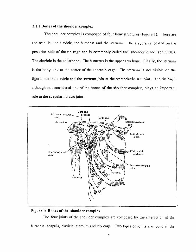
2.2.1 Labral morphology
The scapula has a lateral facet
called the glenoid fossa on which the
humeral head motion occurs. -4 layer
of cartilage covers the fossa and
extends into a rim of sofi tissue called
the labrum. Figure 2 is a planar view of
the lateral side of the labrum anatomy.
Howll and Galinat ( 1989) described
the labruni as a circumferential. fibrous
and pear shaped band that enlarçes the
glenoid fossa. It provides 50% of the
socket depth. They found that the
glenoid articular srirtàce and the labnim
conibiw to produce a socket
r
Moore. Figure 2: Normal 1:ibruni (:idaiireci fi-oiii
approsimately 9nim deep in the - , - ,
superior-inferior direction and jmm in the anterior-posterior direction. The labnim
increases the diameter of the glenoid surface to 73% of the humeral head diameter in the
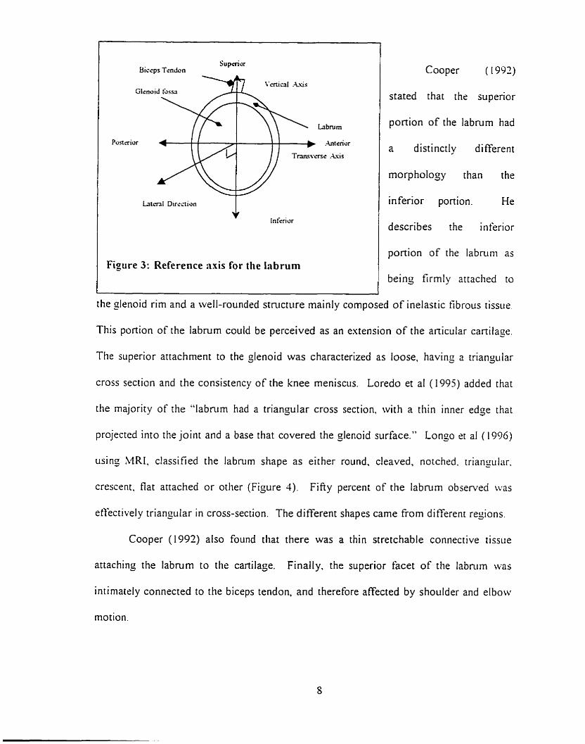
vertical direction and 57% in the transverse direction (Rames 1993). Figure 3 describes
the labnini and the convention for the axes and sections that will be used in this work.
I Sup&or Biccps Tendon
Glcnu
Posttrior
L r i t ~ n l Direction
Infcriur
Figure 3: Reference axis for the Inbrum
Cooper ( 1992)
stated that the superior
portion of the labmm had
a distinctly different
rnorphology than the
inferior portion. He
describes the inferior
ponion of the labnim as
being firmly attached to
the slenoid rim and a well-rounded structure mainly cornposed of inelastic tibrous tissue.
This portion of the labrurn could be perceived as an extension of the anicular cartilage.
The superior attachment to the çlenoid was characterized as loose, having a triangiilar
cross section and the consistency of the knee meniscus. Loredo et al ( 1995) added that
the majority of the "labmm had a triangular cross section, with a thin inner edge that
projected into the joint and a base that covered the glenoid surface." Longo et al (1996)
using MRI. classified the labnrm shape as either round, cleaved, notched. triangular.
crescent, flat anached or otlier (Fijure 3) . Fifiy percent of the labmrn observed was
etfectivel y triangular in cross-section. The different shapes came €rom di fferent regions.
Cooper (1992) also found that there was a thin stretchable connective tissue
attaching the labrum to the cartilage. Finally. the superior facet of the labmm was
intimately connected to the biceps tendon, and therefore affected by shoulder and elbow
motion.
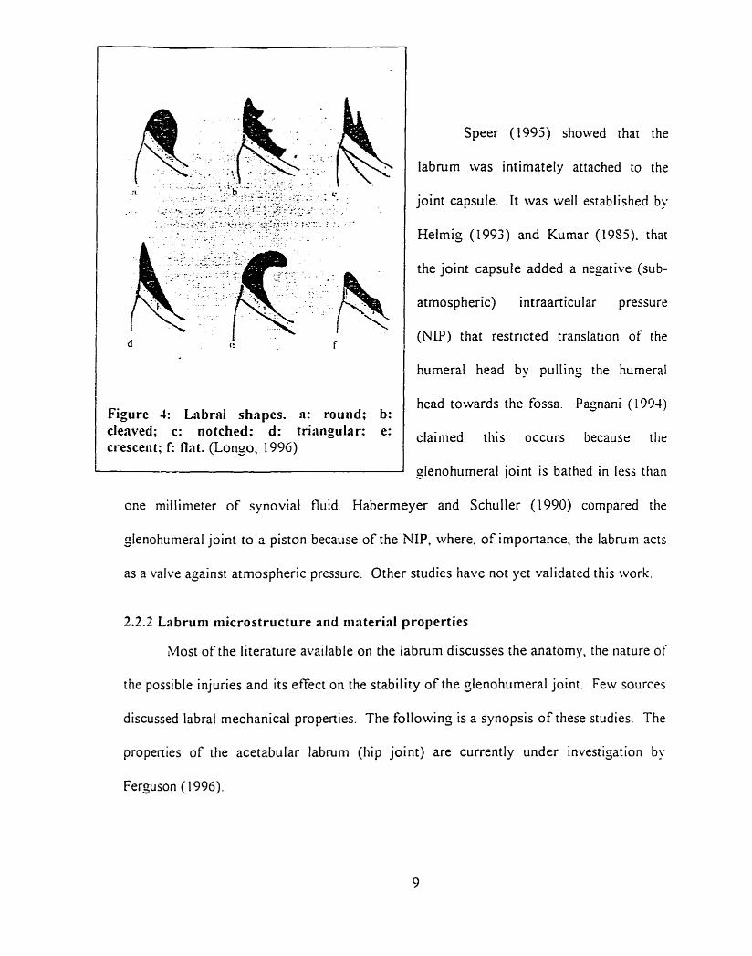
Figure 4: Labral shapes. a: round; b: clenved; c: notched: d: tri:ingular; e: crescent; I: flnt. (Longo, 1996)
Speer (1995) showed that the
labrurn was intimately attached to the
joint capsule. I t was well established by
Helmig (1993) and Kumar (19Sj). that
the joint capsule added a negative (sub-
atmosp heric) intraarticular pressure
(NP) that restricted translation of the
humera1 head by pulling the humeral
head towards the tossa. Pagnani (1994)
claimed this occurs because the
glenohumeral joint is bathed in less tlian
one miilinieter of synovial fl~iid. Habermeyer and Schuller (1990) compared the
glenohumeral joint to a piston because of the N P . rvhere. of importance, the labmrn acts
as a valve açainst atrnospheric pressure. Other studies have not yet validated this work.
2.2.2 Labrum niicrostructure and rriaterial properties
Most of the literatiire available on the labrum discusses the anatomy, the nature of
the possible injuries and its etTect on the stability of the glenohumeral joint. Few sources
discussed labral mechanical propenies. The following is a synopsis of these studies. The
propenies of the acetabular labmm (hip joint) are currently under investigation by
Ferguson ( 1996).
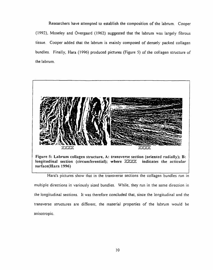
Researchers have attempted to establish the composition of the labmm. Cooper
(1997), Moseley and ~vergaard (1962) suggested that the labrum was largely fibrous
tissue. Cooper added that the labmm is mainly composed of densely packed collagen
bundles. Finally, Hara (1996) produced pictures (Figure 5) of the collajen structure of
the labrurn.
Figure 5: Lnbrum collagen structure, A: transverse section (oriented radially); B: longitudinal section (circurnferential); where F- indicates the acticular surf;ice(Hara 1996)
Hara's pictures show that in the transverse sections the collapen bundles run in
niultiple directions in variously sized bundles. While, they run in the sarne direction in
the longitudinal sections. It was t herefore concluded that, since the longitudinal and the
transverse structures are different, the material properties of the labrum would be
anisotropic.
2.3 Lrs &rd injurier
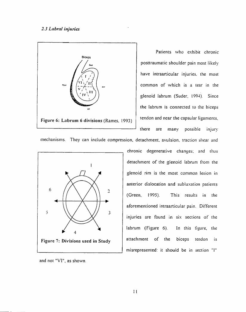
Figure 6: Lnbrlim 6 divisions (Rames. 1993)
Patients who eshibit chronic
posttraumatic shouldrr pain niost l i kely
have intraanicular injuries. the most
common of which is a tear in the
glenoid labrurn (Suder. 1994). Since
the labnim is connected to the biceps
tendon and near the capsular ligaments.
there are many possible injury
mechanisrns. They can include compression. detachment. avulsion. rraction siiear niid
Figure 7: Divisions used in Study
chronic degenerative changes: and diils
detachment of the glenoid labruni froni the
glenoid rim is the most common lesion i r i
anterior dislocation and sublusation patients
(Green, 1995). This results in the
aforernentioned intraarticular pairi. Different
injuries are found in sis sections of the
labrurn (Figure 6). In rhis tipiire. the
attachment of the biceps tendon is
misrepresented: i t should be in section "1"
and not "VI", as shown.
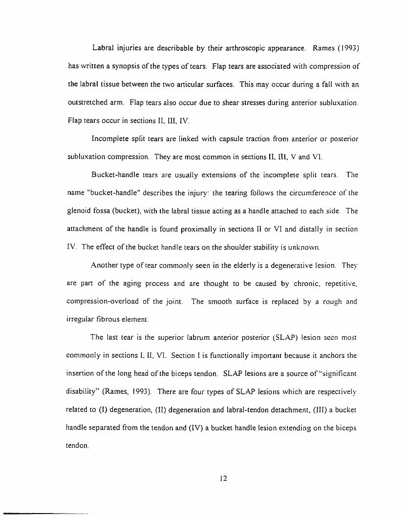
Labral injuries are describable by their arthroscopie appearance. Rames ( 1993)
has written a synopsis of the types of tears. Flap tears are associated with compression of
the labral tissue between the two anicular surfaces. This rnay occur during a fall with an
outstretched arm. Flap tears also occur due to shear stresses during anterior sublusation.
Flap tears occur in sections II, III, IV.
Incomplete split tears are linked with capsule traction from anterior or posterior
subluxation compression. They are most common in sections II. III, V and VI.
Bucket-handle tears are usually extensions of the incomplete split tears. The
name "bucket-handle" describes the injury: the tearing follows the circumference of [lie
glenoid fossa (bucket), with the labral tissue acting as a handle attached to each side. The
attachment of the handle is found proximally in sections II or VI and distally in section
1 . The effect of the bucket handle tears on the shoulder stability is unknown.
Another type of tear commonly seen in the elderly is a degenerative lesion. They
are pan of the açinç process and are thouçht to be caused by chronic. repetitive.
compression-overload of the joint. The smooth surface is replaced
irregular f i brous element.
The last tear is the superior labrum anterior posterior (SLAP)
by a rough and
esion sccn rnoat
comrnonly in sections I. 11, VI. Section 1 is functionally important because it anchors the
insertion of the long head of the biceps tendon. S L M lesions are a source of "significant
disability" (Rames, 1993). There are four types of SLAP lesions which are respectively
related to (1) deçeneration. (II) degeneration and labral-tendon detachment, (III) a bucket
handle separated from the tendon and (IV) a bucket handle lesion estending on the biceps
tendon.
To summarize, the labral injuries are mostly caused by anterior compressive and
shear stresses from the humeral head. Evlaffet (1995) States that the SL.@ lesions are aiso
caused by tensile forces from the long head of biceps tendon fiom lifting tasks and
sudden compression forces from throwing-type motions.
Ail these cases of labral loading lead to believe that labrum properties should bc
quantified to measure its capacity to resist such loading.
The total motion of the shoulder is due to the sum of the motion of the four joints
that comprise it. The only important joint for this study is the glenohumeral joint sincs
the labrum is found in this joint. As such, the stability mechanism of the other three
joints will not be examined.
The glenohumeral joint has six degrees of freedom (Hanyman. 1992). The
largest motions are rotations, which occur about a11 three axes. This agrees with the
theoretical detinition of a bail and socket joint. In addition. the gienoid fossa has a l q s r
radius of curvature then the humera! head; therefore the head can roll, slide and translate
in al1 directions on the fossa's non-congruent surface. The translation motion is sniall
cornpared to the rotation. but still permits greater motion. When the arm is relased or
during lifting, distraction is also possible. Studies by Harryman (1990) have showii t h n t
the maximum translation on the glenoid fossa recorded was of the ordrr of 2-h i i i .
Therefore. the "bail and socket" assumption is reasonable for man- analyses. When
discussing the role of each shoulder component. it is customary to th ink in terins of
stability. A stable joint is defined as a joint, restrained only by the surroiindino
anatoniical structure. t hat undergoes normal p hysioloçical motion undrr riornial
physiological loading. Lazanis ( 1 996) added an important pan to shoulder stability bu
defining it "as the individual's ability to maintain the humeral head precisely ceiitered
within the humerai joint." Both statements provide a compiete definition.
The range of motion of the çlenohumeral joint is greater than ans other joint in
the body (Pagnani. 1994). including 1 80° of abduction-adduction, 1 SOO of iriternal-
esternal rotation and almost 135" of forward-backward flexion. Kumar (19S5) has
argued that joint stability is thus sacrificed- to permit the increased ranoe of motion and
consequently. subluxation or dislocation can more easily occur. Lazams (1996) deîïned
shoulder stability "as the individual's ability to maintain the humeral head precisely
centered within the jlenohumeral joint." Since the glenohumeral joint does not have the
bony restraints found in other joints, the ligaments and muscles surrounding it have
become the prirnary stabilizers (Pagnani 1994). Therefore. the glenohumeral joint could
not maintain this stable position on the body within the 24mm range nientioned by
Harrynan ( 1 990) without them.
Sectioning studies (Warren et a1 (1984). O'Brien et al (19SS). Blasier et al (1997))
have s h o w that many of the restraints could be escised before the joint would dislocate.
However. excising one restraint would &en lead to instability in the specitic direction
that the restraint acted.
2.4. I Dyriniiiic sta bilizers
The main stabilizing muscle çroup is the rotator cuff. I t has been s h o w b!,
Blasier et al. (1997) that contraction of the rotator cuff retains the hiimeral hrnd i i i the
glenoid fossa. The rotator c u f acts like a dynamic capsule in which tendons provide
dynam ic restraint to anterior. posterior and inferior displacements of the Iiiiitieral tiead.
This is considered dynamic restraint since, in the passive state. the muscles do not
provide much support and hnction based on the force-elongation relationship for
muscles; passive support is provided by ligaments, the NIP and the labruni. Pajnarii
( 1 994) States that the contractions of the muscles compress the hunieral head into the
glenoid fossa. increasinç the force required to translate the head.
The effect of the biceps brachii on-humera1 head motion has also been srudied.
Pagnani indicated that the long head of the biceps '%ad a significant etfect on
glenohumeral translation." He stated that "tension in the biceps reduced anterior
translation when the arm was internally rotated and reduced posterior translation when
the a m was externally rotated, especially if the a m was in mid elevation." The biceps
are important stabilizers in racket sports like tennis.
Finally. the scapular rotaror muscles also affect the olenohurneral stability since
they position the scapula to provide a stable base underneath the humeral head. [toi et al.
(1992) found that the scapular inclination prevents inferior translation of an abducted
arni.
2.1.2 Static stabilizers
Static stabilizers are anatomical components that passively rrstrain t hci joint.
Unlike bal1 and socket joints ( e g , hip) which possess circumferential bony stability, the
glenohumeral joint only has such constraints in elevation. The çlenoid fossa surface area
is much smaller than the humeral head, but it does possess a superior lip that can restrict
the hunienis tiorn hiyhly excessive superior translation. Damaginç rhis constrairit ha5
lead to larger humeral head translation and higher incidences of dislocation (Xkdloii.
1995). The coracohunieral ligament also provides superior stabilization. This liynnierit
and the acromion prevent excessive elevation of the humeral head.
The shape of the humeral head is another imponant element. Bone defects in the
hunieral head or the relationship of the humerai head on the çlenoid fossa have been
shown to affect glenohumeral stability. Improper contact would produce improper
motion since the humeral head would not be constrained to its proper motion path.
It has been previously rnentioned that the synovial capsule of the shoulder has a
role in the stability of the joint. Within the capsule there is a negative pressure
differential. This acts as a sucrion cup and retains the humerai head in the gienoid fossa.
Warner (1993) said that this nesative pressure prevents translation of the humeral head
by providing between 89 and 135 Newtons of force. The capsule walls have limited
extension. Thus, the capsule itself, as structure, is a translation-restricting element.
Studies. reported by Pagnani (1994) have demonstrated that resection of the capsule
causes more translation of the humeral head since the tissue no longer constrains motion
and the NIP has been lost.
The glenohurneral joint has three anterior capsular ligaments, the superior, niedial
and inferior ligaments. The involvernent of these ligaments is largely associated wi t h
arm abduction. At 0' elevation. the superior ligaments have the dominant role. At 45'
and 90' of elevation, the inferior ligaments are dominant. In al1 three cases. the medial
lijaments provide secondary support. It is not known precisely at what point the
transition between the inferior and superior ligament dominance happens. These
ligaments also have a degree of importance in the internai rotation of the Iiurnenis and of
the humeral head translation in various directions (Pagnani. 1994). trnagining two
structures attached by three loose strings in a triangular shape should clarify this point.
Figure S shows the restrictive role of these ligaments.
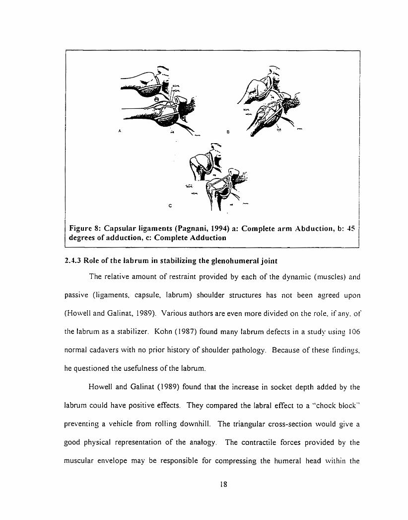
Figure 8: Capsular ligaments (Pagnani, 1994) a: Complete arni Abductioii, b: 45 degrees of adduction, c: Complete Adduction
2.1.3 Role of the labrurn in stnbiliziiig the glenohumeral joint
The relative amount of restraint provided by each of the dynaniic (niuscles) and
passive (ligaments. capsule. labruni) shoulder structures has not been agreed u p o n
(Howell and Galinat, 19S9). Various authors are even more divided on the mie. if aiiy. of
the labnirn as a stabilizer. Kohn (1957) found many labrum defects in a study iising 106
normal cadavers with no prior history of shoulder pathology. Because of these tiiidings,
he questioned the usefulness of the labrum.
Howell and Galinat (1989) found that the inçrease in socket depth added by the
labmm could have positive effects. They compared the labral effect ro a .'check blocKT
preventing a vehicle from rolling downhill. The triançular cross-section would &ive a
good physical representation of the analogy. The contractile forces provided by the
muscular envelope may be responsible for compressing the humeral head witliiii the
glenoid-labral socket; thus providing the ball and socket kinematics seen in stable
sockets. The authors also state that a darnaged labrum would not be able ro produce the
hoop stresses required to retain the humeral head. "Based on this study of the socket. r hs
loss of the labmrn would be an important etiologic factor in anterior stability" (Hon.cll
and Galinat, 1989).
.A final point mentioned by Howell and Galinat was that the pliable labmm and
conforming characteristics of the cartilage might explain the intimate association of t lie
anicular surfaces in the in-vivo. physiolo;ically loaded shoulder. A study by Harqnian
et al (1990) on the translation of the humeral head on the glenoid with passive
gienohurneral motion. saw that the profile of the labrum chanjes with hunleral Iiead
rotation. This suççested tliat the cornpliance of the cartilage and labruni could help the
articular surfaces of the glenoid and the humerai head to conform during translatioii OZ
the humeral head. This could imply another level of restraint provided by the labriim.
This means that at different angles of arm rotation, the capsule and the labrum. under the
influence of moments pull the humerai head towards the ~lenoid.
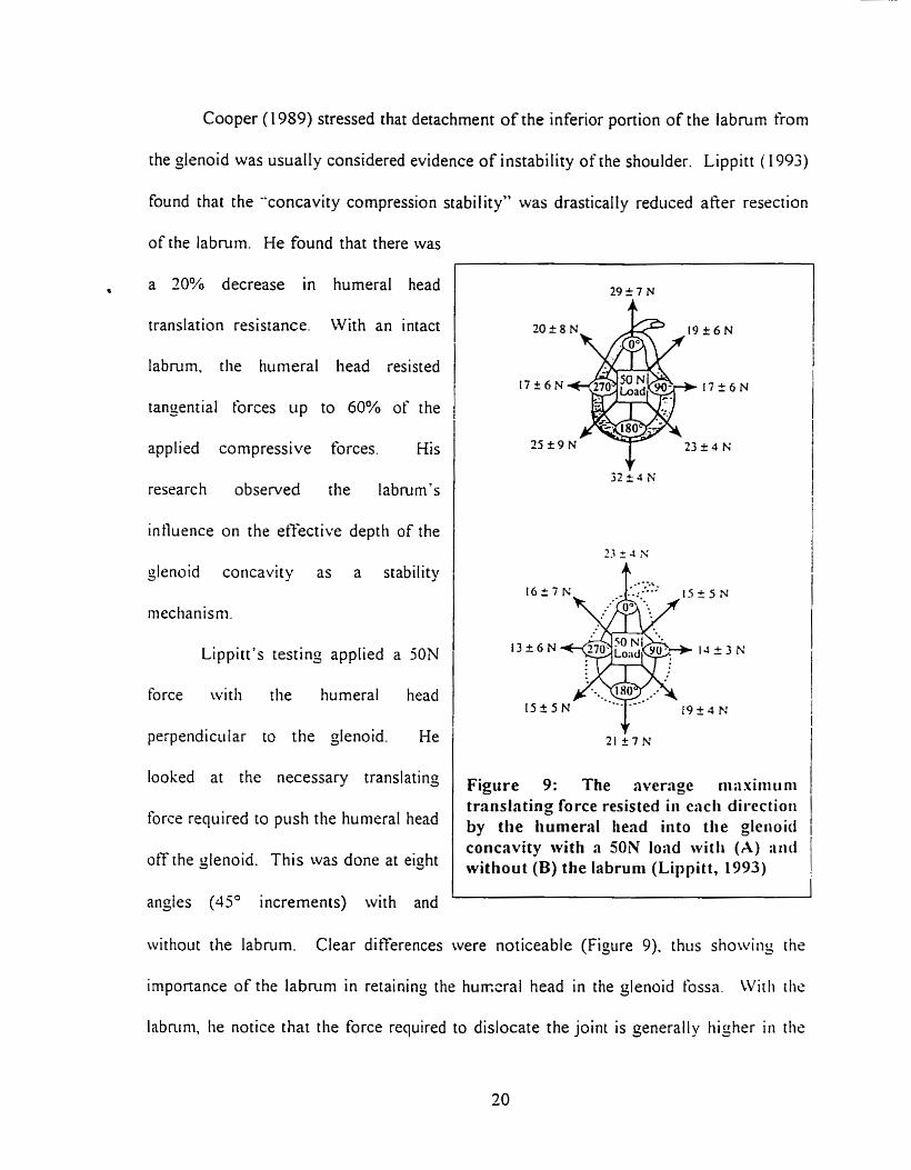
Cooper ( 1989) stressed that detachment of the inferior portion of the labnirn from
the glenoid was usually considered evidence of instability of the shoulder. Lippitt ( 1 993)
found that the "concavity compression stability" \vas drastically reduced afier resection
of the labnirn. He found that there was
, a 20% decrease in hurneral head
translation resistance. With an intact
labrum, the humeral head resisted
tangenrial forces up to 60% of the
applied compressive forces. Kis
research observed the labmm's
intluence on the efiective deptli of the
glenoid concavity as a stability
mechanisni.
Lippitt's testing applied a 5ON
force witli the hurneral head
perpendicular to the glenoid. He
looked at the necessary translating
I force required to push the humeral head
off the glenoid. This was done at eiçht
angles (45' increments) with and
Figure 9: The average niiixiiiiiini trûnslnting force resisted iri eacli directioii by the humera1 head iiito the gleiioid concavity with a 50N load witli (A) :mi without (B) the labruni (Lippitt, 1993)
witliout the labnirn. Clear differences were noticeable (Figure 9). thiis showiriy t hr
importance of the labrurn in retaining the hunxral head in the glenoid tossa. Witli die
labnini, lie notice that the force required to dislocate the joint is çenerally tiigher ii i the
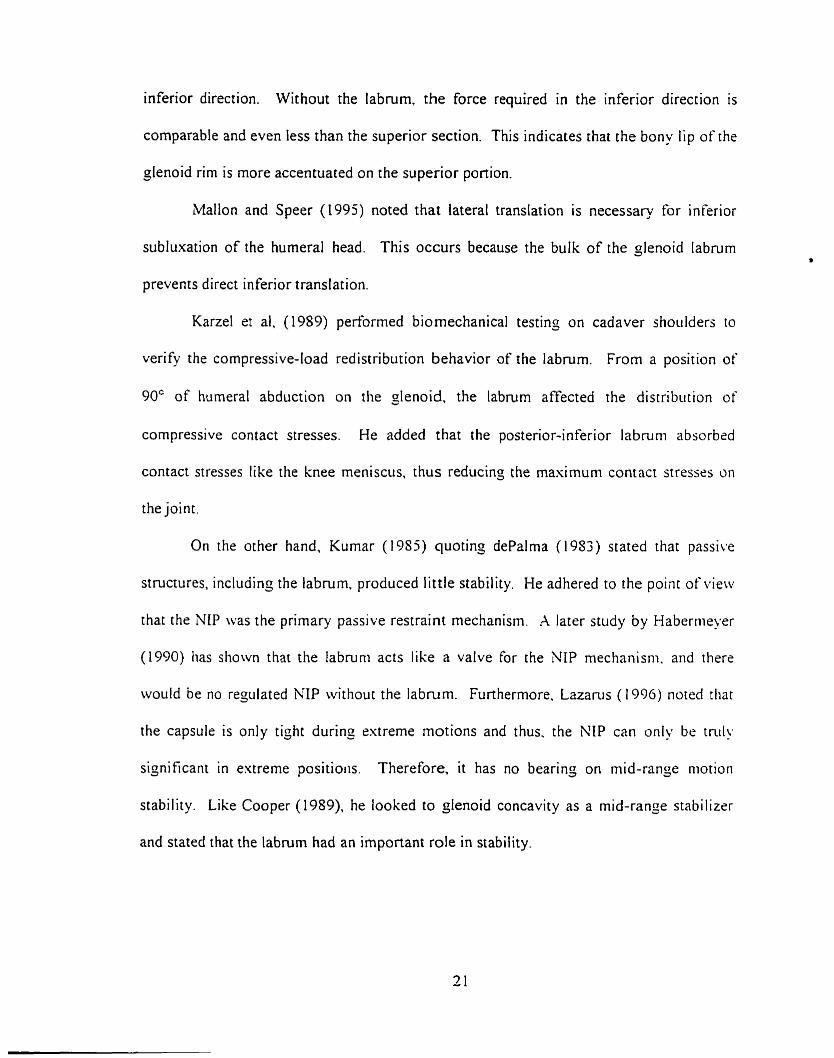
inferior direction. Without the labmm, the force required in the inferior direction is
comparable and even less than the superior section. This indicates that the bon- lip of the
glenoid rim is more accentuated on the superior portion.
Mallon and Speer (1995) noted that lateral translation is necessar-y for inferior
subluxation of the humeral head. This occurs because the bulk of the glenoid labmm
prevenrs direct inferior translation.
Karzel et al. (1989) perforrned biomechanical testing on cadaver shoulders to
verify the compressive-load redistribution behavior of the labmm. From a position of
90' of humeral abduction on the =lenoid. the labrum affected the distribution of
compressive contact stresses. He added that the posterior-inferior labnim absorbzd
contact stresses like the knee meniscus. thus reducing the maximum contact stresses on
the joint.
On the other hand, Kumar (1953) quoting dePalma (1983) stated tliat passive
structures, includinj the labmm. produced little stability. He adhered to the point of vieiv
that the NIP was the primary passive restraint mechanism. A later stiidy by Haberiiieyer
(1990) has shown that the Iabruni acts like a valve for the NIP mechanism. and there
would be no regulated NIP without the labmm. Furthermore. Lazarus (1996) noted tliat
the capsule is only t içht during estreme motions and thus. the NIP can only be tnil!
significant in extreme positioiis. Therefore. it has no bearinç on mid-range niotiori
stability. Like Cooper (1989). he looked to glenoid concavity as a mid-range stabilizcr
and stated that the labrurn had an important role in stability.
2.5 Review of differerent testing procedures
Two methods are currently used to observe the compressive response of soîi
tissue. The first is the confined compression test; the other is indentation testin;. Both
are well documented in the literature and commonly used. Indentation testinj is
performed with either a porous or non-porous indentor. The study will examine elastic
propenies and will therefore not use a porous indentor used to observe viscous propçnies.
In a following section. the results of different testing procedures performed on the
labrum. not related to indentation, will be discussed. Some of them have important
elements that are usehl to desijning an indentation test protocol of the labmm. However.
none of the foilowing studies indicated if any pre-conditioning was performed.
Reeves' testing (1968) subjected the Iabmm to a shearing force to obtain the
required force to detach the anterior-inferior pan of the labrum from the glenoid. This
procedure lefi the labrum attached to the plenoid. The neck of the scapula was severtd
and embedded in a block of dental Kaffer D ~ " cernent. The plane of the labral
anachment was set parallel to the surface of the block. He used two machines to perform
the tensiometry studies. The tirst recorded the slowly rising load as a chanje in the
resistance of a helical potentiometer attached to a spring balance, while labral stretch \i.aj
recorded by a lever writinç on a smoked drum. The second "was a load cell attached to a
moving clamp and a hydraulic ram, toçether with a displacement sensor attaclied to a
fked clamp" (Reeves 1968). No details on the ram were provided, but it appears to have
been a small indentor.
Woo (1987) proposed another method to obtain cartilage compression stiffness.
The confined compression test presses the specimen in a cylindrical die using a ngid
permeable block to permit fluid flow from the tissue. Ferguson (1996) proposed testing
the mechanical propenies of the acetabular labrum using a confined compression test to
jenerate data for a finite element modei. This could validate stiffness findings from this
study.
Spilker (1992) performed finite eiement analysis of the indentation stress-
relaxation response of articular cartilage using a linear biphasic model. The stiidy
showed that indentation testing was a valid method for obtaininj the basic mnterial
propenies. He stressed that the used of a biphasic model was essential for shon terni
(less than 1 second) stress-relaxation testing.
To define cartilage stiffness. Messner and Gillquist (1 993) used a tlat ended. non-
porous, 1-nini diameter indentor. The load-compression curve was calculared using ten
loads incremented by 0.025N (0.032 m a ) . The compression curves were adjusted for
each cartilage thickness. They found that the compression curves were Iinear above
0.025 N with correIation coeftlcients p a t e r than 0.97.
Many authors have discussed usinç indentation tests to obtain siicli propenics as
the stitfness, hardness, modulus of elasticity and viscoelastic propenies. Sakabayashi
(1994) performed an indentation test to determine bone strençth; Crawford (1995) and
Rasanen (1996) examined the rnodulus of elasticity in cartilage using indentation lests.
They evaluated the stiffness under ramp loading with a 0.7mni diameter solid.
cylindrical, flat-ended indentor. A load of O. 1 N (0.26 MPa) was applied with a steep
ramp function with a rise time less than 200 ms. He obtained the thickness of the
cartilage by piercing the center of the indented area with a needle and measuring the
depth of penetration.
Aithough the confined compression test can be used to obtain basic material
propenies, it mainly is helpful in obtaining tirne dependent properties used in biphasic
viscoelastic models. Funhermore, the confined compression instruments are very
expensive.
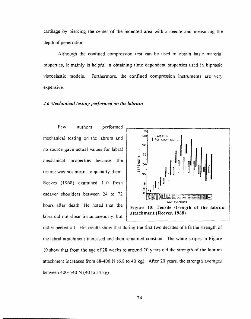
2.6 ~Mdiotiicnl testing perfurmerf on the lnbrit ni
Few authors performed ,
mechanical testing on the labnirn and
no source gave actual values for labral
mechanical properties because the
testing was not meant to quantify them.
Reeves (1968) examined 1 10 fresh
cadaver shoulders between 24 to 72 1 hours afier death. He noted that the
labra did not shear instantaneously. but
AG€ GROUPS
Figure 10: Tensile strengtli of the Iabriitii attachmeri t (Reeves, 1968)
- - --
rather peeled off. His results show that during the first two decades of life the strengtli of
the labral attachment increased and then remained constant. The white stripes in Figure
10 show that from the age o f28 weeks to around 20 years old the strength of the labruni
attachment increases from 6S-400 N (6.5 to 40 kg). After 20 years. the strengh averages
between 400-540 N (40 to 54 kg).
Hara (1996) observed the role of the glenoid labrum and capsule in the prevention
of shoulder dislocation. He tested h m wide radial strips of the glenoid labmrn and
capsule in tension. These stnps were attached to the glenoid until the time of rupture.
The usual rupture site was the portion of the anterior-inferior labmm close to the glenoid
cartilage. The required mean force for rupture for the anterior-inferior portion was
reponed as 3.84 = 1 .O0 kgjrnrn. This was the weakest region (section 3). It is the belief
that this means that it took approslrnately 37.3 5 9.8 N on average to rupture the 5rnm
wide strips of capsule-labrum from the glenoid rirn. He indicated that in the lower half
the forces ranged from 3-03 + 1.39 kg (29.7 ~ 1 3 . 6 N) to 5.2 1 i 2.54 kg ( 5 1. I = 24.9 A?.
Hara did not perform tensile tests on the superior portion of the labmm and therefore. and
did not indicate if there was a difierence in the rupture force between the superior and
inferior portions of the labrum.
Collasen structures and associated mechanical propenies have been esamined in
man' studies using Fung's ( 196s) quasi-linear model (Haut ( 1977). Jenkings ( 197-1).
Sanjeevi (1982). Woo (1992)). No such study on the labmm could be found. However.
Fung's model is appropriate for relaxation testing of tissues and provides parameters of
limited value for tissues under compression.
From the collagen microstructure of the labmm, a viscoelastic response is
expected. During loading, a viscoelastic material should have an initial strain and then a
creep reçion. When unloading the material, a rapid decrease in strain is visible followed
by a more gradua1 recovery. The simplest model of a recoverable sofi tissue follows the
behavior of a three-parameter solid (linear sprinç in series with a spring and dashpot
system in parallel). Load and loading rate are important factors to consider in
determining the test procedure. Canilage and labrum can both be analyzed using this
model having the bone as a rigid backing. Obtaininç the appropriate sprins and darnper
constants can define the behavior of the substances.
However. using rapid indentation can render the viscous properties nezligible and
it can be assumed that the linear spring propenies to be the greatest causes of
displacement. Viscous resistance is proportional to strain rate. Therefore. it is reasonable
to assume that at high strain rates. the viscous system will deflect little. If wr assume the
bone acts as an infinitely long rigid materiai, the anatomical system (labniiti mer
cartilage) can be analyzed, at least initially. as two springs in series. This shoiild directiy
provide the compressive resistance of the materials. Eberhardt et al (1990) used data
provided from other indentation and confined compression studies. Froni tliese. tliey
have justified the use of an elastic mode1 for tests where loading did not esceed 200 ins.
Simulations done in the undertaken study, using meniscal and cartila=inoiis
propenies validated the use of hiçh strain (200 mmlsec) indentations to obtain elastic
propenies. Differences between the three-parameter viscoelastic solid and the elasric
solid were 2.7 $6 afier I O mm of simulated indentation.
Knee meniscus and joint canilage are the tivo substances most sirnilar to the
labrum. The knee rneniscus is a crescent shaped tissue thinner at the center rhan at the
circumference. Like the labrum. the meniscus is a collajenous structure useful for load
bearing, shock absorbing and joint stabilizing. The matrix of the meniscus is Rbrous with
large rope-like collagen packs aligned in the circumferential direction. while srnaller
collagen fibers are aligned in the radial direction. Both the labmm and knee rnenisîi
estend or attach to the articular cartilage. As aforementioned. the labmm is cornposed of
an upper section that resembles knee rneniscus in appearance and an inferior section rhat
resembles carti tage.
Many studies have used finite element analysis models for indentation testing on
canilage. There is no clear method of analyzing cartilaginous and rneniscal tissue. Both
have been esamined as single-phase elastic tissues and biphasic viscoelastic tissues.
The material properties found by both models are different. The general shape of
the curves for sofi tissue compression Stans with a toe region and then jocs ro a steeper
linear region. It is cornplicated to obtain the first non-zero point of the toe region because
it has a slope nearing zero but not neçliçible. The following rable summarizes rhr
various findings on both tissues using indentation testing. In the tables. E is the modiilus
of elasticity or the tangent niodulus in the linear region. The açgreçate modulus defines
the compressive response of both phases in the biphasic mode!. AISO detailed is the
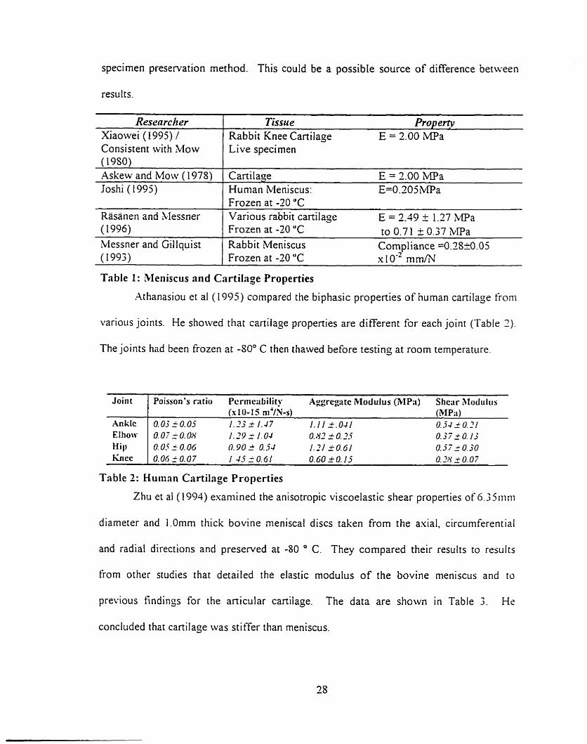
specimen preservation method. This could be a possible source of difference between
results.
Consistent with Mow 1 Live specimen
Resenrclzer Xiaowei ( 1 995) /
I
Askew and Mow (1975) ( Cartilage E = 2.00 MPa
Tissu e m e $ p Rabbir Knee Cartilage E = 2.00 iMPa
Joshi ( i 995) 1 Human Meniscus: E=O.2OSbPa 1 Frozen at -20 "C
Rasanen and Messner 1 Various rabbit cartilage E = 2.39 i 1.27 k P a
(1993) 1 Frozen at -20 "C x 1 0.' m h T
( 1996)
Messner and Gillquist
Table 1 : Meniscus and Cartilage Properties
Athanasiou et al ( 1995) compared the biphasic properties of human canilage froni
Frozen at -20 "C to 0.71 + 0.37 MPa Rabbi t Meniscus Cornpl iance =0.2S20.05
various joints. He sliowed that canilaje propenies are different for each joint (Table 2)
The joints had been frozen at -SOO C then thawed before testinç at room temperature.
Table 2: Humnn Cartilage Properties
Joirit
Ankk EIhow Hill
f i cc -
Zhu et a1 ( 1 994) esaniined the anisotropic viscoelastic shear propenies of 6.3 511ini
Poisson's r;itio Pcrnic;ibiIity Aggregtc iklodulus (3IP;i) Shcar Alodiiliis (s 10- 15 m4/Ws) (3IP;i)
O.OjiO.05 1.23 2 1.47 1.1 1 3.041 0.54 2 O. 21 O. O? f O. 08 1.29 = 1.04 O. 83 i O. .?-Y 0.57 2 O. 1.3 0.05 i 0.015 0.90 I 0.j4 1.21 50.61 0.37 r 0.30 O.OGfO.07 1.45 10 .61 0.60 _ ; O . I j O.2N _i 0.07
diarneter and 1.Omm thick bovine rneniscai discs taken from the asial, circurnferential
and radial directions and preserved at -80 O C. They compared their results to rrsults
€rom other studies that detailed the elastic modulus of the bovine rneniscus and to
previous findinçs for the anicular cartilage. The data are shown in Table 3. He
conciuded that cartilage was stiffer than meniscus.
Material Section rLvial meniscal disk
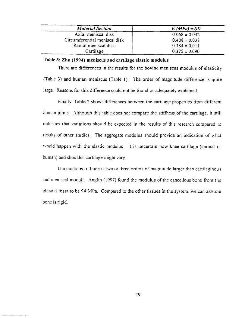
(Table 3) and human meniscus (Table 1). The order of magnitude difference is quite
- - - --
E ~ I P ~ ) + SD 0.068 = 0.042
Circumferential meniscai disk Radial meniscaI disk
Cartilage L
large. Reasons for this difference could not be found or adequately explained.
0.408 i 0.033 0.384 = 0.0 1 1 0.375 * 0.090
Finally, Table 2 shows differences between the cartilage propenies frorn differrnr
Table 3: Zhu (1994) meniscus and cartilage elastic modulus
There are differences in the results for the bovine meniscus modulus of eiasticity
human joints. Although this table does not compare the stiffness of the cartilage. it still
indicates that variations stioi~
resulrs of other studies. The
Id be espected in the results of this research compared ro
: asgregate modulus should provide an indication of ivhar
would happen with the elastic modulus. It is uncertain how knee cartilage (animal or
tiunian) and shoulder cartilaçe might Vary.
Ttie niodulus of bone is two or three orders of magnitude larger than canilajinous
and nieniscal rnoduli. Ançlin ( 1997) found the modulus of the cancellous bone froni the
slenoid Fossa to be 94 M ' a . Compared to the other tissues in the system. we cm assunie
bone is rigid.
2. I O Thesis objectives
This chapter examined the important aspects of the current literature on
compression testing of sofi tissues. The shoulder is composed of many structures. one of
which is the labmm. The labtum is a fibrocartilaginous tissue, with a different
morphology in the superior and inferior portions, which surrounds the glenoid fossa. It
helps to support loads, retains the intraarticular fluids and finally provides stability to the
gleno humeral joint.
To fulfill its roles. ir must be able to resist compressive loading. As such. this
study will determine the compressive response of the labmm using rapid indentation
testing. To test the compressive response of the glenoid labnirn it was necessary to
mode1 the anatomical system. It was hypothesized that the anatomical system would be
represented as the labmm coverinç the articular cartilage. The bone could act as a rigid
backing to the system since it is much stiffer than the labmm and cartilage. Thus, two
tissues were being compressed: the labrurn and the articular cartilage.
The anatomical system was modeled as two springs representinj the labmm and
the cartilage on a rigid bone backing. The bone should act as a rigid substance under
rapid testinç. The tests were conducted on the tissue and substrate because this would
cause less disruption to the tissue.
The larger occurrence of injuries in the superior, compared to the inferior.
portions of the labnirn suggests that the two distinct morphologies will have different
material properties. To validate the previous use of cartilage and meniscus properties to
describe the labrurn. this study will attempt to cateçorize, the different rnaterial properties
of the labmm by cornparing with other studies done on cartilage and meniscus.
Chapter 3: Methodology
The objective of the study was to obtain the compresske response of the glrnoid
labrum. As such, a testing procedure had to be devisrd to test this anatomical systern in
situ. This chapter describes the instrumentation, protocol and analysis uscd.
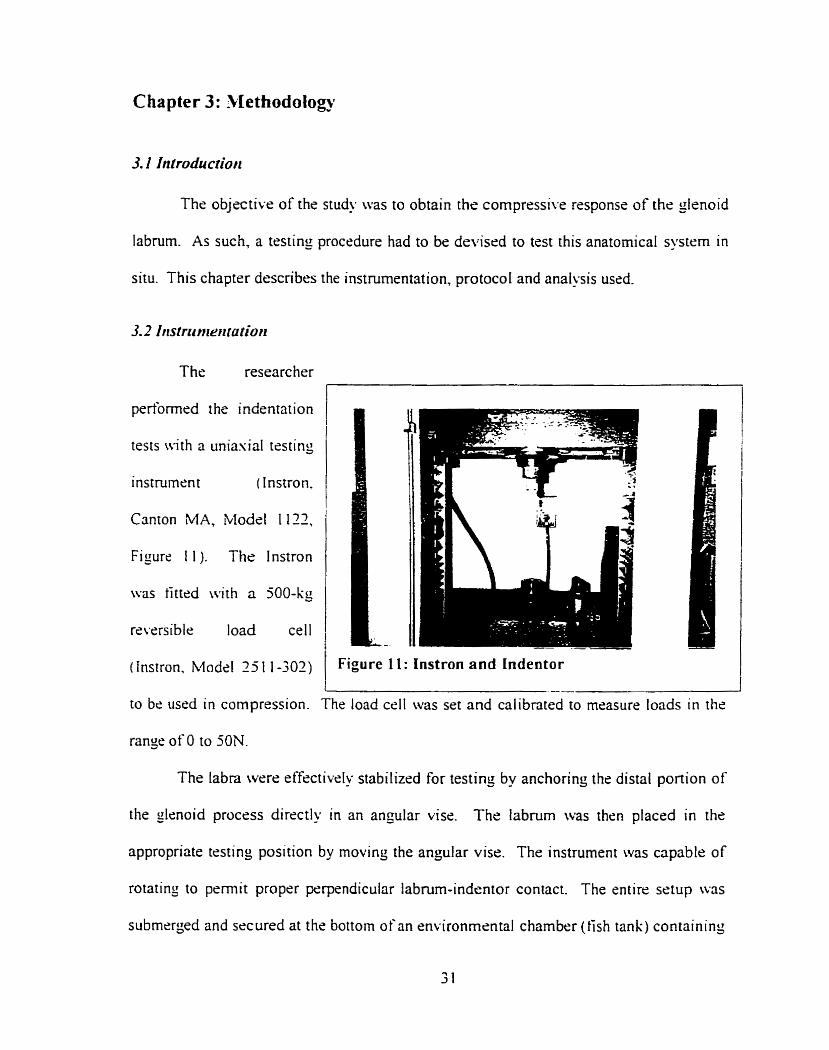
3.2 Iristrct rrtrrtratior~
The researcher
pedbmwd the indentation
tests with a uniasial testing
instrument (Instron.
Canton MA, Model 1 I12,
Figure 1 1 ). The 1 nstron
\vas tittrd with a 500-kg
rsversible load ceil
( instron. Modcl 25 1 1-302) Figure I l : Instron and Indentor
range of O to 50N.
to bc usrd in compression. The load ce11 was set and calibnted to measure loads in the
The labra werr effectivelu stabilizrd for testing by anchoring the distal portion of
the glenoid procrss directly in an angular visr. The labnim was thsn placed in the
appropriate tcsting position by rnovinç the angular visr. The instrument was capable of
rotating to permit propcr perpendicular labrum-indrntor contact. The entire setup w3s
submcrged and secured at the bottom of an environmental chamber (tish tank) containing
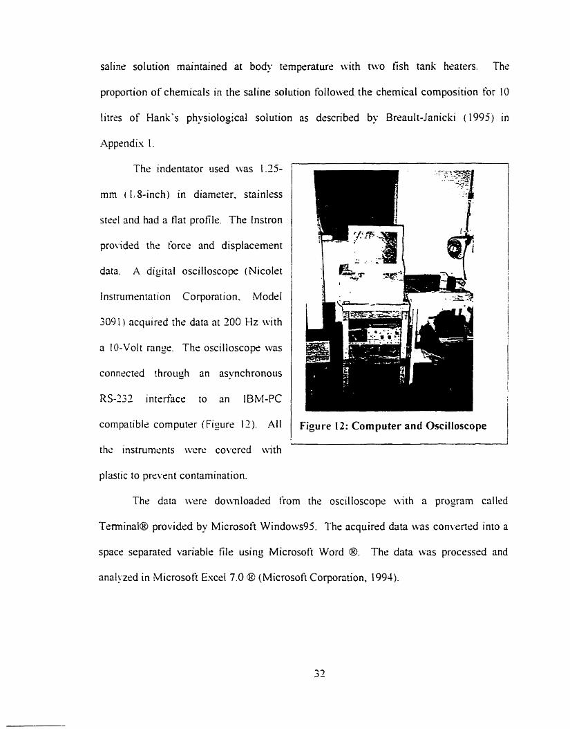
saline solution maintained at body temperature with two Fish tank hraters. The
proponion of chernicals in the saline solution followed the chernical composition for 10
litres of Hank's physioiogical solution as descri bed by Breault-Janicki ( 1995 j in
Appendis 1.
The indentator used was 1.15-
mm ( 1,s-inch) in diameter, stainless
steel and had a flat profile. The tnstron
provided the force and displacement
data. A digital oscilloscope (Nicolet
lnstrumsntation Corporation. Modrl
3091 ) acquired the data nt 200 Hz with
a IO-Volt range. The oscilloscope was
conneetrd t hrough an asynchronous
RS-233 intertàce to an IBM-PC
compatible computer (Figure II). Ail
the instrumcn ts wcrc co\*crcd with
plastic to praPerit contamination.
Figure 12: Cornputer and Oscilloscope
The data were do\vnloaded from the oscilloscop<: with a proyram callcd
Terminal@ providcd by Microsoft Windows95. The acquired data was convened into a
space separated variable file using Microsoft Word O. The data was processrd and
anal!ïxd in Microsoft Escrl 7.0 @ (Microsoft Corporation, 1994).
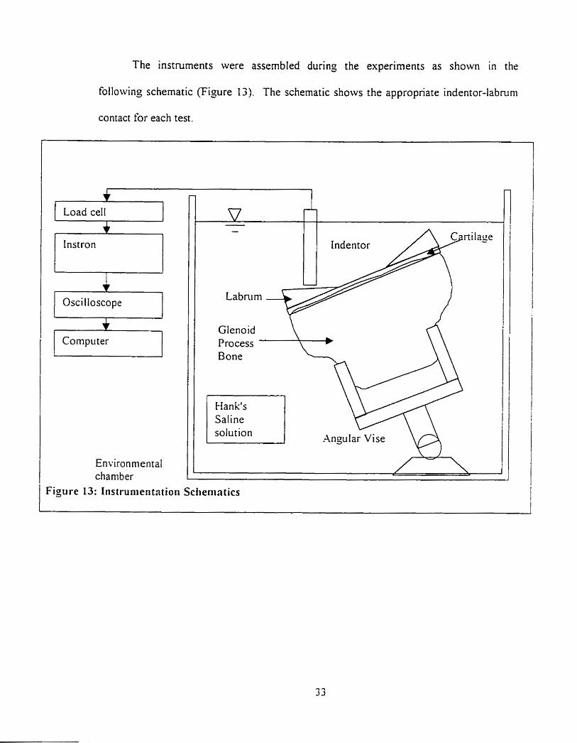
The instruments were assembled during the experiments as shown in the
following schematic (Figure 13). The schematic shows the appropnate indentor-labnim
contact for each test.
1 Load cell 1
Instron 77 Oscilloscope i Compii ter 1
Environmental charnber
Indentor
Gtenoid Process Bone
Han k's Saline solution
Figure 13: Instrunieri tntioii Sclienintics
Angu 1 ar Vise VA
3.3 Specinren collection and prepnrntion
3.3.1 Specimen collection
Queen's University's Anatorny Department provided six adult labra. three right
and three lefi, From three embalmed cadavers. The embalminj procedure had been
performed in the 3 to 4 months preceding the testing. It is believed that embalming
changes the propenies of the labra. but embalmed specimens should still provide
information on the difference in the properties between the circumferential sections.
To gain access to the glenohumeral joint, it was first necessary to remove the arrn.
With the cadaver placed facing downward on the dissection table. it was simpler to
access the muscles and lijarnents retaining the humerus. Cuts were made low enough on
the hurnerus to preserve the biceps tendon's attachment on the labrum. The insenion of
the biceps tendon was preserved since it was s h o w that it influences the labral stabilit!.
mechanisms (Cooper 1992). Deep cuts to the posterior, superior and anterior portions of
the shoulder permitted detachment of the deltoid, biceps, pectoralis major and
supraspinatus muscles.
Having removed these muscles. it was possible to remove the remaining smaller
muscle attachments and ligaments from the humeral head and the glenohumeral capsule
by scrapinç the bone wirh a scalpel. The arm was now fully detached from the body.
The removal of the arm ensured that no labral damaçe would occur by directly removing
the scapula from the body.
The second part was to remove the scapula from the posterior thoracic cage. The
first step was to carefùlly cut the acromioclavicular joint with a scalpel. A longer scalpel
was used to cut the subscapularis muscles from under the scapula, thus freeing it from the
posterior side of the cadaver's thoracic cage. Once the scapula was detached. a vibrating
handsaw was used to remove the glenoid process From the scapula.
The excess tissue was removed rneticulously with scalpels and scissors to expose
the labrum. Labra were clearly different in size. thickness and fat tissue content. These
observations will be detailed in the results section dealing with the anatomical findings.
The proximal portion of the glenoid process bone was cut to a wedge shape using a
scalpel to ensure solid gripping during the experiments.
Specirnens were stored in ZiplocTM bags. in a sealed toolbox under a tùme hood
before and afier testing. Although embalmed tissues are a level 1 biohazard. the
specirnens were stored in a wet lab using biohazard level 2 precautions. Safety measures
associated wit h this laboratory were strictly followed to prevent contamination of
personnel and equi pment.
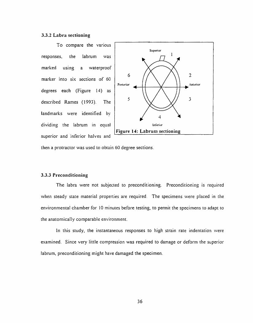
3.3.2 Labw sectioning
responses, the Iabrum was
marked using a waterproof
marker into sis sections of 60
degrees each (Figure 14) as
described Rames (1 993). The
landmarks were identified by
dividing the labrum in equal
superior and inferior halves and
To compare the various
1 Figure 14: Lnbruni sectionirig
Supèrior
then a protractor was used to obtain 60 degree sections.
3.3.3 Preconditioning
The labra were not subjected to preconditioning. Preconditioning is required
when steady state material propenies are required. The specimens were placed in the
environmental chamber for 10 minutes before testing, to permit the specimens to adapt to
the anatoniically comparable environment.
In this study, the instantaneous responses to hiçh strain rate indentation were
esarnined. Since very little compression was required to darnage or deform the superior
labrum. preconditioning rnight have damaçed the specimen.
3.4 Erperhental protocol
Gross observations such as tissue damage were noted. Vernier calipers (= 0 . 0 3
mm) were used to measure the outer dimensions at the central leve1 of the labrum.
The thickness of each of the six sections was also measured using the Vernier
calipers. The thickness was taken in the center of each section at angles of 30, 90. 150.
2 10. 270 and 330 degrees ro the horizontal as an approximation to the averase thickness.
The actual uncertainties are estimated to be 5% of the measurement due to the ditlïculties
in identifyin~ tissue margins.
Prior to testing, the lnstron load cell was set and calibrated to measure loads in the
range of O to jON. The saline solution was heated to 37 O C with two tish tank heaters
The vise was submerged in the solution and with its suction cup was anchored to the
bottom of the tank. Then. the labral surface was rotated and secured parallel to the tlar
surface of the indentor.
The crosshead was lowered ont0 the labrum until a rninor offset Ioad, in the order
of O. 1 N, was perceived. The crosshead was then slowly moved back until the otyset Ioad
returned to zero. This was selected as the initial point of zero loading and displacernent.
Strain could not be calculated since the initial thickness could not be nieasured
without damaoins - the labrum. and the tissue thickness varied across the indentor (Figure
1 3 ) The indentations were performed perpendicular to the interior facet of the labruni.
If possible, the indentation tests were performed 3 times in each section.
Indentations were performed at a distance of I to 2 indentor diameters from each other.
If the specimen was too small io permit this distance between them, indentations were
performed only twice in this section. Cornpressing a tissue does not only affect the tissue
direcriy under the indentor but also the surrounding tissue. Near the indentor boundary,
the effects are unrecoverable, but fûrther away from the indentor boundary the effects are
minimized and neglected. Each section had an approximate arc Iength of 1 - 5 2 cm.
Thus. one to two indentor diameters were left as space between indentation sites to
minimize the loading effects.
Wth respect to the microstructure described by Hara ( 1996). the indentations
were performed against the bundled collagen fibres. Although the collagen fibers do not
al l run in the same direction, they still have a main direction.
Followin; Rasanen and Messner's rnethod (1996), the load increased as a steep
ramp tùnction peaking within 0.200 seconds. This was achieved by havins the Instron
set at a strain rate of 700mm/min. The load increase was performed until the indentor
reached the mechanical stop of the Instron. At this point the indentor would have
contacted with the cartilage and bone surface because the mechanical stop was placed at a
level lower than the bone surface. There was 5-minute period between each indentation
to permit the tissue surrounding the indentation area to recover from the efiects of the
force application. At high strain rates the rnaterial acted as a elastic soiid. but once the
load was rernoved, the specimens recovered their initial shape within 30 seconds. The 5
minutes was used to ensure total recovery and downloadinç of Instron data.
3.5.1 Data analysis
The information gathered during the indentation testing was convened to force/
displacement curves using Excel (Figure 15). While indentation was to be pedormed
perpendicular to the iabral surface. it was di fficult to obtain perfectl y perpendicular
contact (Figure 16). It was therefore necessary to correct the graphs to obtain the tnie fi111
indentator contact point (Le. take out sections before "c" of Figure 15). This measure
ensures that the graphs from al1 the tests start at the same initial point. This also perniits
the rernoval of the initial zero points due to the space between the indentor and the labral
surface before t esting.
Selection of the ful l indentor contact was done by an analysis of the data and first
derivative of the data. Despite al1 the efforts in trying to obtain proper contact between
the indentor and the labral surface. it was impossible to ger perfect contact because of the
tissue shape. Therefore, there woiild initially be partial contact. First. it was necessary to
idenrify the first point of contact (point "a" of Figure 15). The first load data point was
subtracred from al1 the followinj points. The data before the value where the ditference
was consistently larger than zero was eliminated as being non-indentor contact and signal
noise (before point "a" of Figure 15).
To find the initial point of full indentor contact, the dope was taken between
points. The first instant the slope was found to be constant was selected as the initial
point of the first linear region (point "c" in Figure 15)
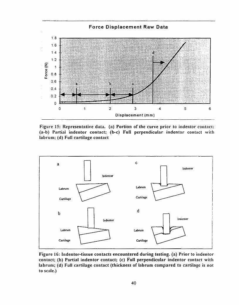
Force Displacement Raw Data
Displacement (mm)
Figure 15: Representative data. (a) Portion of the curve prior to indeiitor coiit:ict: (a-b) Partial iiideritor contact; (b-c) Full perpeiidicular indentor coiit:ict with labruni; (d) Full cartilage con tact
n indcnt or
Figure LG: Iiidentor-tissue contacts encountered during testiiig. (a) Prior to iiideritor contact; (b) Partial iiidentor contact; (c) Full perpendicular indentor coiitact witli la brun^; (d) Full cartilage contact (thickness of iabrum compared to carti1a;c is i iot
to scale.)
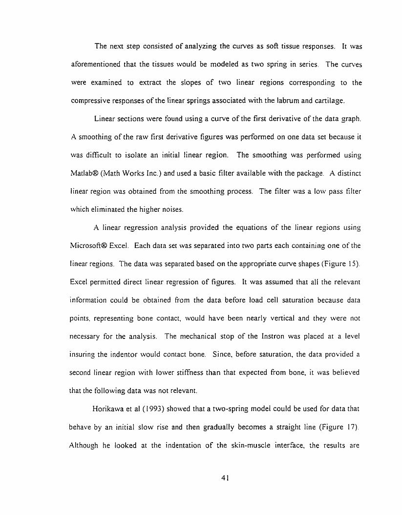
The n e a step consisted of analyzing the curves as soft tissue responses. It was
aforementioned that the tissues would be modeled as two spring in series The curves
were examined to extract the slopes of two Iinear regions corresponding to the
compressive responses of the linear springs associated with the labrum and cartilage.
Linear sections were found using a curve of the first derivative of the data gaph.
A smoothinj of the raw first derivative figures was perfonned on one data set because it
was difficult to isolate an initial linear region. The smoothing was performed using
Matlab@ (Math Works Inc.) and used a basic filter available with the package. A distinct
linear region was obtained from the smoothing process. The filter was a low pass tilter
which eliminated the higtier noises.
A linear regression analysis provided the equations of the linear regions iising
blicrosoft@ Excel. Each data set was separated into two parts each containing one of the
linear regions. The data was separated based on the appropriate curve shapes (Figure 15).
Excel permitted direct linear regression of figures. It was assumed that al1 the relevant
information could be obtained from the data before load ce11 saturation because data
points. representing bone contact, would have been nearly vertical and they were not
necessary for the analysis. The mechanical stop of the Instron was placed at a level
insuring the indentor would contact bone. Since, before saturation, the data providcd a
second linear reçion with lower stiffness than that expected from bone. it was believed
that the following data was not relevant.
Horikawa et al (1993) showed that a two-sprinç mode1 could be used for data that
behave by an initial slow rise and then gradually becomes a straiçht line (Figure 17).
Although he looked at the indentation of the skin-muscle interface. the results are
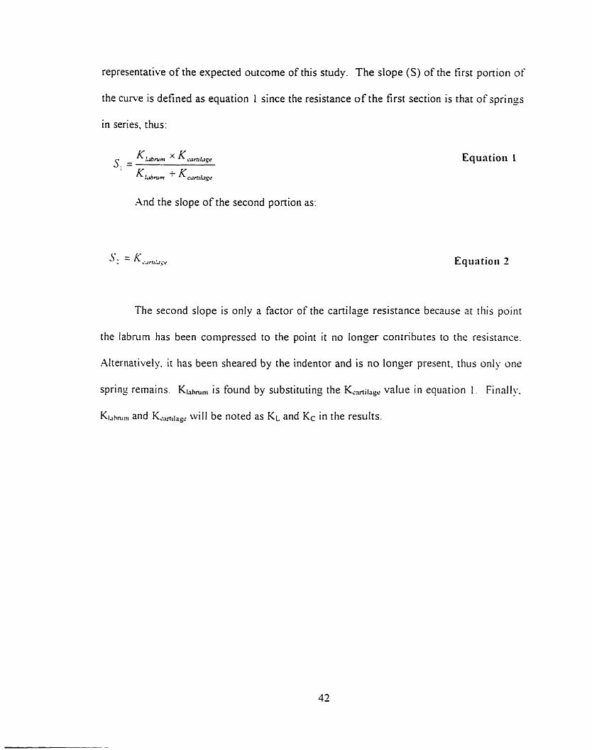
representative of the expected outcome of this study. The dope (S) of the first portion of
the curve is defined as equation 1 since the resistance of the first section is that of springs
in series, thus:
And the dope of the second portion as:
The second slope is only a factor of the cartilaje resistance because at tliis point
the labmrn has been compressed to the point it no longer contributes to the resistance.
Alternatively. it has been sheared by the indentor and is no longer present. thus only one
sprins remains. Klahmni is fo~md by substitutinj the KCafiii,, value in equntion 1 . Finally.
KIJhmm and KM,,,, will be noted as KL and Kc in the results.
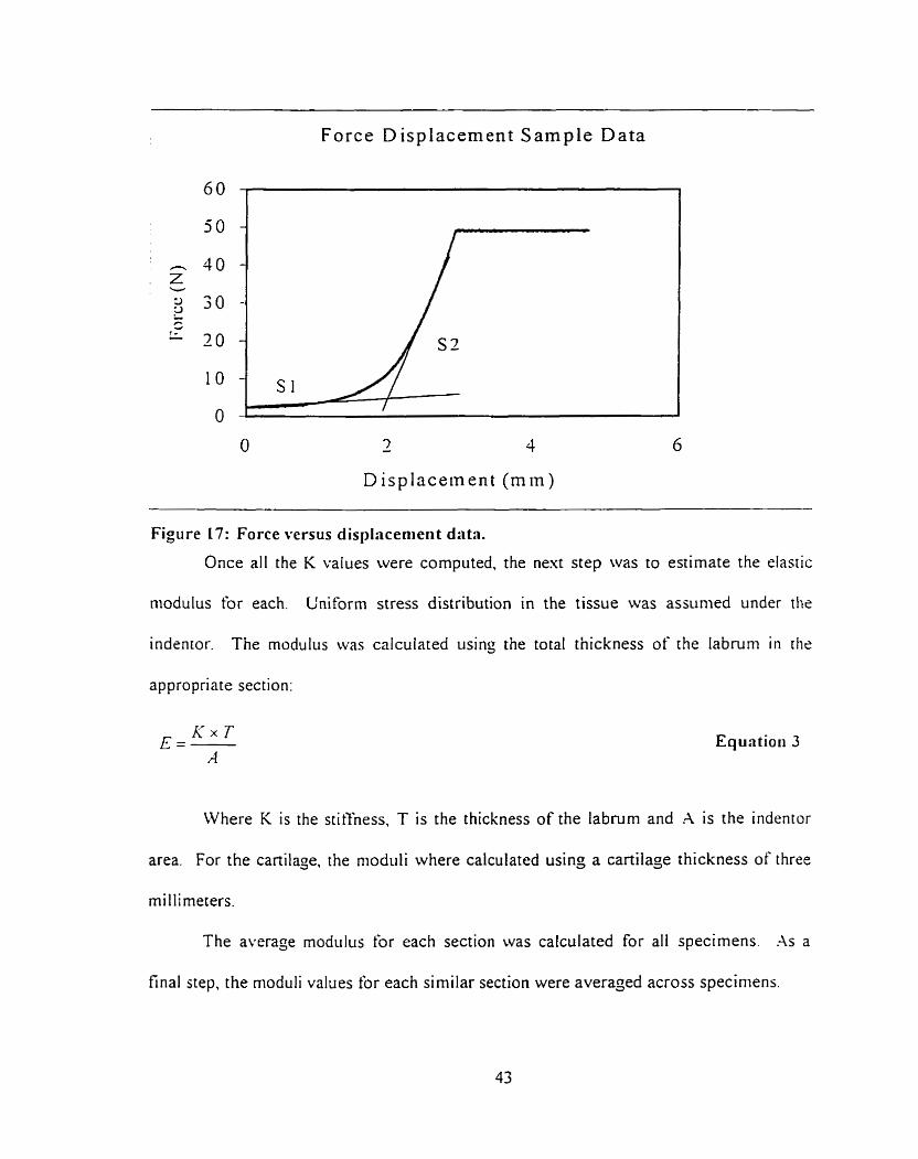
Force D isplacement Sample Data
7 - 4 6
D i splacement ( m i n )
Figure 17: Force versus displacenieri t data.
Once al1 the K values were computed, the next step was to estimate the elastic
niodulus for each. L'niforrn stress distribution in the tissue was assunied under the
indentor. The modulus was calculated using the total thickness of the labruni in the
appropriate section:
Where K is the stit't'ness, T is the thickness of the labnirn and A is the indentor
area. For the cartilage, the niodiili where calculated using a cartilage thickness of three
rnillimeters.
The average modul~~s for each section was calculated for al1 specimens. .As a
final step, the rnoduli values for each si milar section were averaged across speciniens.
3.3.2 Error rnslysis
An error analysis was performed on the gathered information. The analysis
assumed a 5% error on al1 collected data as a standard engineering error. Therefore. the
follo~ving equations were derived frorn previous equations to provide the uncertainty
(eVmJbl,) of each variable. However, the error on the thickness of the labmm could be as
high as 100% because the indentations did not cornpress the f u l l thickness of the tissiie.
The results for the rnodulus therefore would still have the same order of magnitude, but
could be substantially off. These errors will be more dominant for the thicker portions of
the labnirn since the thinner tissues were flatter.
The diameter error was 0.25mm thus, the error for the area was calculated as 3 1.7
For the slopes (S St=Kc) the errors are related to the calculated displacements
and load ceIl data sent directly to the computer. Uncertainty for the slopes c m be
esaggerated and set at 5% for each.
Based on equation 1, the uncenainty for KL is:
Based on equation 3 , the uncertainty for the elastic modulus is:
Equatiori 4
3.5.3 Statistical analysis
The structural stiffness and elastic modulus results were compared using analysis
of variance. This procedure compared the aforementioned variables against the nul1
hypothesis that the groups were drawn from the same population. The resulting moduli
information were compared between labra for each of the six test sections.
In addition, the structural stiffness and modulus of each section rvere analyzed
with the other sections within a single labrum. Performing this showed if propenies for
different sections were comparable for each labrum. Since there rvere morphological
difèrences between labra, it was easier to compare intra-labrum K variations than direct
labrurn to labrum section cornparison. Both cornparisons perniitted a betrrr
understanding of the compressive response of the different sections.
Takins three tests per section increased the power of the statistical testing. Eacli
labruni was indented 18 times. For proper statistical analysis, each samplr had to be
independent of other sarnples. randoml y selected in a normal1 y distributed popiilat ion in
which the variance of each popiilation was equal even if the means were different
(Glantz. 1992). It was assumed that the labra samples obtained complied with the
principles of a norrnally distributed population. Signiticance was assunied p < O O 5 for
all tms.
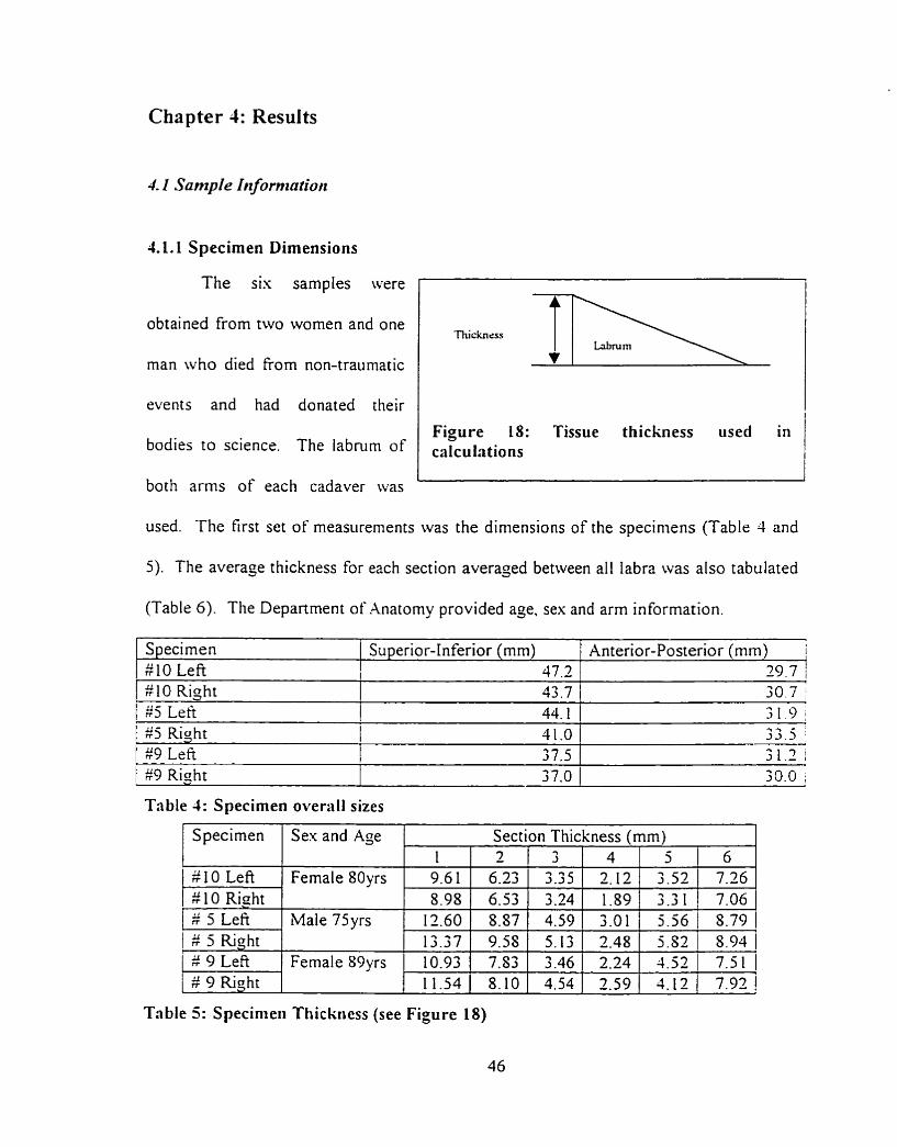
Chapter 4: Results
4. I Sarnple h i formation
41.1 Specirnen Dimensions
The sis samples were
obtained from two women and one
man who died from non-traumatic
events and had donated their
bodies to science. The labrum of
both arms of each cadaver was
Figure 18: Tissue thickness used in caIculations
used. The first set of measurements was the dimensions of the specimens (Table 4 and
5) . The average thickness for each section averaged between al1 Iabra was also tabulated
(Table 6). The Depanment of Anatomy provided age. sex and arm information.
Specimen #10 Left
I 1 25 Right 11.0 / 3 3 . 5 [ $9 Left 1 37.5 1 31.2 i
$10 Right $5 Le%
Superior-Inferior (mm) 47 3
43.7 ( 30.7 i 44.1 31.9
Table 4: Specirnen overall sizes
Anterior-Posterior (mm) i 2 0 7 1
/ #9 Right 37.0 1 jO.0 ;
Table 5: Specinieii Thickness (see Figure 18)
Specimen
# 10 Left # 10 Right # 5 Lefi
1 # 5 Right # 9 Lefi # 9 Riaht
SexandAge
Fernale 80yrs
Male 75yrs
Female S9yrs
Section Thickness (mm) 1 9.61 5.98
12.60 13.37 10.93 11.54
2 6.23 6.53 8.87 9.58 7.53 8.10
6 7.26 7.06
3 3.35 3.24 4.59 5.13 3.46 4.54
4 2.12 1.89
5 3.52 3.3 1
3.01 2.48
5.56 5.S2
5.79 1 8.93
2.24 1 4.52 2.59 ( 4.12
7.5 1 7.92
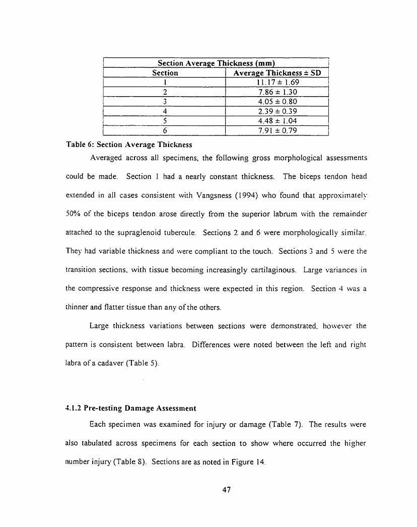
Section Average Thickness (mm) 1
--- ---
Table 6 : Section Average Thickness
Averaged across al1 specimens, the following gross morphologicai assessments
Section 1 1
could be made. Section 1 had a nearly constant thickness. The biceps tendon head
Average Thickness k SD 11.17 % 1.69
estended in ail cases consistent ivith Vangsness (1994) who found that approsimatel!
50% of the biceps tendon arose directly frorn the superior labrum with the remaindrr
attached to the supraglenoid tubercule. Sections 2 and 6 were morphologically similar.
They had variable thickness and were compliant to the touch. Sections 3 and 5 were the
transition sections. wi th tissue becoming increasingl y cartilaginous. Large variances in
the compressive response and thickness were espected in this region. Section 4 was a
thinner and flatter tissue than any of the others.
Large thickness variations between sections were demonstrated, however the
pattern is consistent between labra. Differences were noted between the lefi and right
Iabra of a cadaver (Table 5).
1.1.2 Pre-testing Damage Assessrnent
Each specimen was exarnined for injury or damaçe (Table 7). The results were
also tabulated across specimens for each section to show where occurred the higher
number injury (Table 8). Sections are as noted in Figure 14.
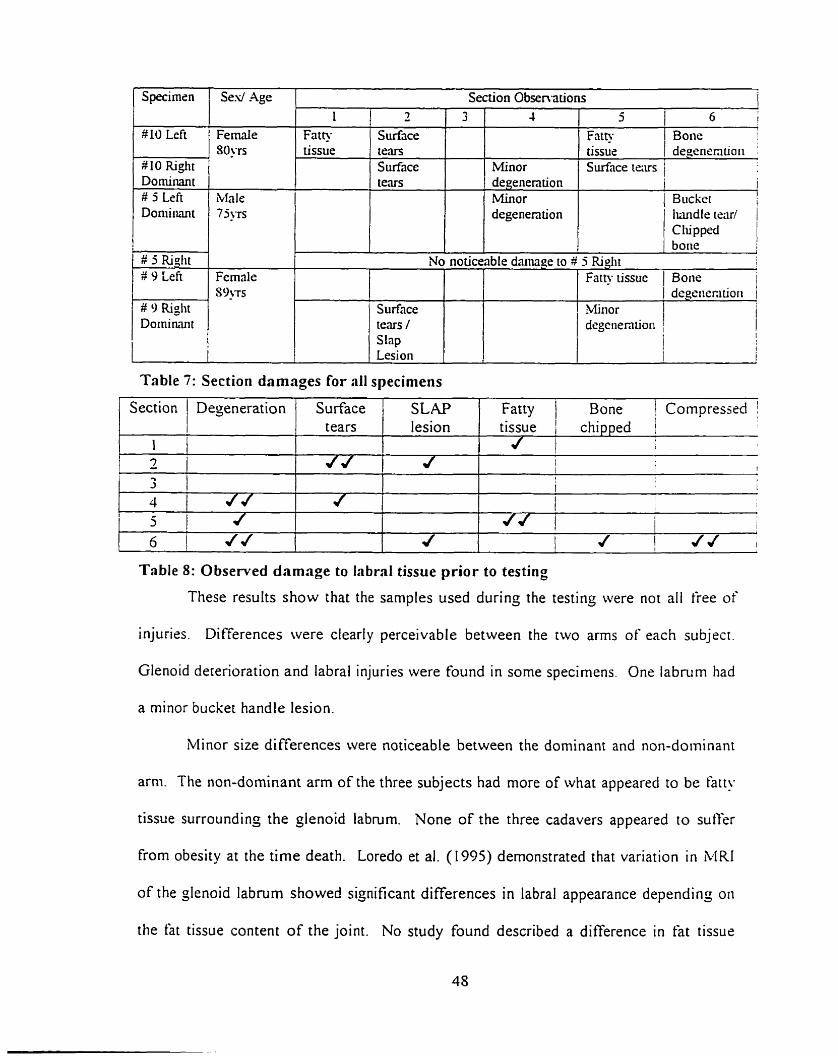
Table 7: Section damages for al1 specimens
Specirnsn
10 LeFt
W 10 Right Dominant # 5 Left Doniirmt
1 # 5 Righi
9 L i e
# 9 Riglit Dominant
I
1 Section 1 Dejeneration / Surface 1 SLAP 1 Fatty / Bone Compresjed !
Ses/ Age
Fernale 30‘~s
Male 7 j j ~ ~
Femrile S ~ ' T S
Table 8: Observed damage to L b r d tissue prior to testing
These results show that the samples used durinç the testing were not al1 free of
1 1 l 2 i 2 I
injuries. Differences were cleariy perceivabl e between the two arms of each subjecr.
Section Obsen-ations
Glenoid deterioration and labral injuries were found in some specimens. One labrum had
tears
a minor bucket handle lesion.
Minor size di fferences were noticeable between the dominant and non-dominant
arni. The non-dominant arm of the three subjects had more of what appeared to be htr!.
tissue surrounding the glenoid labrum. None of the three cadavers appeared to sutfer
from obesity at the time death. Loredo et al. (1995) demonstrated that variation in MRI
of the glenoid labrum showed significant differences in labral appearance depending on
the fat tissue content of the joint. No study found described a difference in fat tissue
3 4
Minor degenention Minor degenention
L Fath tissue
lesion
5 1 6 I
1 Fat@ I tissue 1 d:gnmtioi, j Surtnce iexs /
1 i 1 Bucket !
Iundle teru/ C lu pped bone
I i
7
Surface te,m Surface tears
No noticeable danage to 3 5 Riglit 1
tissue chipped j l 1
1 t I
! i t
Surface tems / Slap
Fatty tissue 1 Bone i / degêiiecitiori 1 Minor degenen tioii
i 1 ;
content between the dominant and non-dominant am. Removal of this fatty tissue was
nearly impossible without darnaging the labrum. A noticeable observation was that the
labmm's interior facet from the dominant a m of al1 the cadavers had been remodeled to
better conform to the humeral head.
Finally. the majority of the labral injuries occurred in the superior sections of rhe
labrum (sections 6.1.2). Ten out of sixteen injuries occurred in the superior sections.
4 2 In den ta tion Test Resrr lts Sis glenoid labra were marked and tested by indentation in sis sections to
evaluate their compressive response. Each labral section was to be tested three times to
obtain an average. Smaller labra could not be tested three times because the indentation
wouid have occurred at less than one indentor diameter from the previous indentation
site. Specimen $5 left section 5. Specimen $5 right section 6 and specirnen $9 righr
sections 3,j and 6 were only tested twice. Section six ûf the left labrum of specimen 9
was orily tested once because the first test ripped the labmm from the glenoid rini.
The following section will provide sarnple raw data. sample calculations. the
stiffness results for each indentation and the average modulus for each labral section.
This will be followed by the statistical analysis and a çeneral error analysis. Results are
initially presented and compared as force versus displacement. The moduli are then
tabiilated for each section and rhen as a single representative labrum.
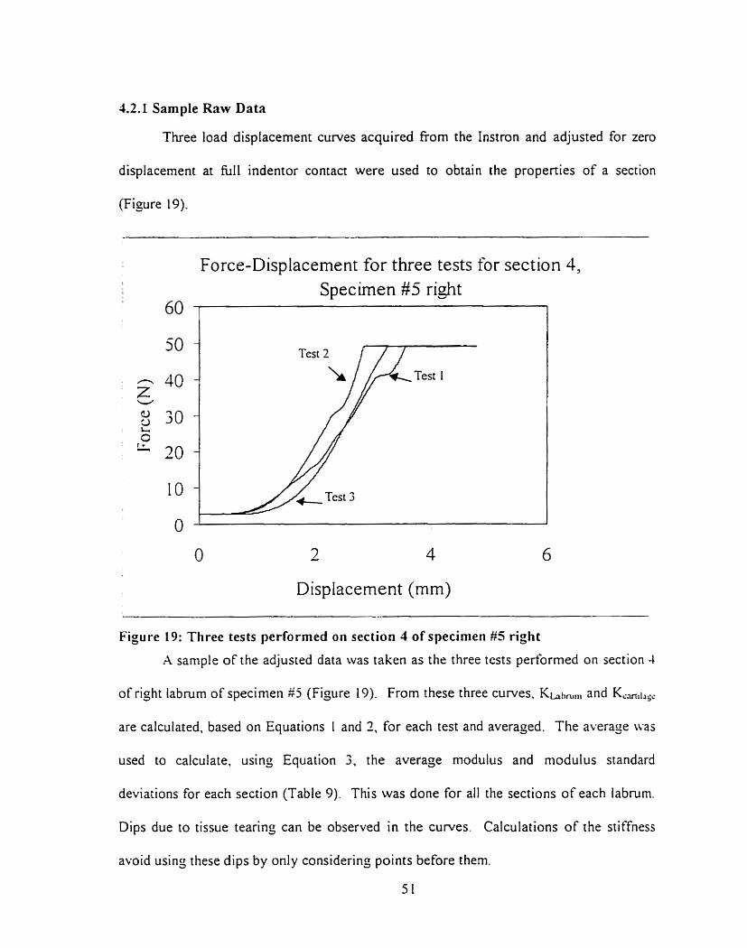
42.1 Sample Raw Data
Three load displacement curves acquired fiom the Instron and adjusted for zero
displacement at hl1 indentor contact were used to obtain the properties of a section
(Figure 19).
Force-Displacement for three tests for section 4, 1
I Specirnen # 5 right 60 1 1
Displacement (mm)
Figure 19: Three tests performed on section 1 of specirnen #5 right
A sample of the adjusted data was taken as the three tests performed on section 4
of right labnim of specimen $5 (Figure 19). From these three curves, Khhnlni and K,,,1,,,
are calculated, based on Equations 1 and 2, for each test and averaged. The average u.as
used to calculate. usinj Equation 3. the average modulus and modulus standard
deviations for each section (Table 9). This was done for al1 the sections of each labrum.
Dips due to tissue tearing can be observed in the curves. Calculations of the stiffness
avoid usin; these dips by only considerin; points before them.
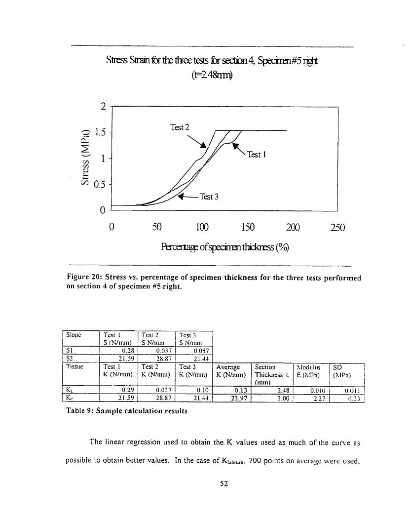
Figure 20: Stress vs. percentage of specimen thickness for the three tests performed on section 4 of specimeii #5 riglit.
The linear regression used to obtain the K values used as much of the c u n e as
possible to obtain better values. In the case of Klabmnl, 700 points on average were iised.
b
Table 9: Sample calculation results
Slopri
S 1
Test I S (Nliiiiii)
0.28
Test? )Tes t3 S N/rniii 1 S Nliii~ii
0.037 1 0.087 S2 1 2 1.59 Tissus
KL
Test 1 K (Wriiiii)
0.39 2 1-59
7S.87 1 2 1.44 Test 2 K (Nliniii)
Average K (N/iniii)
O. 13 23.97
Test 3 K (Nliiiiii)
0.037 1 0. 10 2S.87 1 2 1.44
Section Tliichess L (111111)
2 . 4 S / 0.0101 0 .011j I
3.00 1 2.27 1 0.33 1
Xlociiilus E (&Pa)
SD I I
(klPn) 1
as for K-m,!,g,, since this linear region was longer, 1500 points were used to define the
slope. In the above figure, when the percentage of specimen thickness esceeds 100°b.
this indicates that the labnim has been completely compressed and that the indentor is
nonr penetratins cartilage.
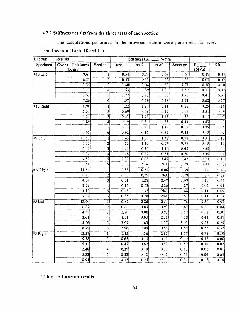
4.2.2 Stiffness results from the three tests of each section
The caiculations performed in the previous section were performed for every
labral section (Table 10 and I 1).
Table I O : Labruni results
Lübnim Sl~ecirncn
"
Results
0vcr;iilThickness 0). mm
test1
# 10 Left
R10 Riglit
Section
- - -
ELbrun, (BI P;t)
O . 1
Stiffness (&abnim), N/mm
$9 Lcft
a 9 Righi
9.6 1 6.23 3-33 2.12
3.52 7.26
8.98
SD
0 . 0 ~ 3
test2
6.53 3 2 4 l,S9 -, 9 - 1 . ~ 1 7.116
10.93 7.83 3 -46 2.24 4.32 7.5 1
1 1.54
test3
O . 0 . 0 2
Aver;igc
1' - 7 -. 3
4 5 G
1
0.1s
O . 11 0.4 1 0.63
0.25
O. '74 0.32 2 .O4 1-39 3-72 3.39
1.27
0.54
O. 43 2.40 1.53 3-77
1.37
1.22
0.10
0.02 0.01
0.27
iJ.tS
3 3 4 3
G
1 2 3 4
5 6
1
0.63 0.3G 0.69 1.36 3 .GO 3-38
O. 14 0.69 0.53 O. 19
O. 14
0.63
0.43 0.93 0.5 1
0.4s 2.72 3.79
0.SS
0.64
0.33 1.71 1.59 3.70 2.7 1
0.SS 3.68 1.75 0.S9 0.33
O. 16
1 .O0
1.20 0.26
0.57 0.03 NIA
0.23
O. 19 1.75 0.25 1.25 0.5 1
1.3 1 il. 17 1.3 1 0.75 1.45 N A
0.06
11.39 1-52 0 .3 1 1.35 0.44
0.57
0.43
0.9 1 0.77 0.69 O . 70 1 -42 3.79
O. 3 O
O. 1JI 0 . 0 7 ,
0.O.î
0 .
O. I O
0.31
O
0 . 0 s
o . o S 0 . 2 0 o o o 0.14
0.02 0.06 0.05
U.15
(1 .13. 0.06
0.0 I o. 19
0.52
0.16
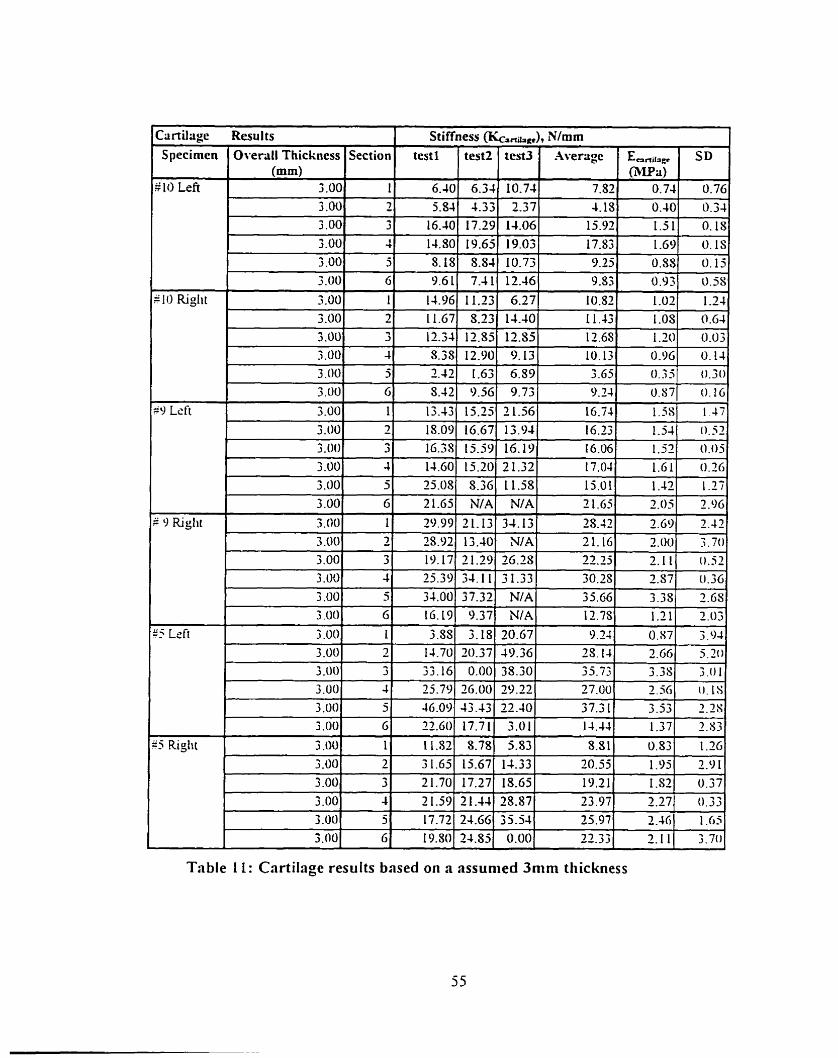
Table 1 1 : Cartilage results bnsed on a assunied 3mm thickness
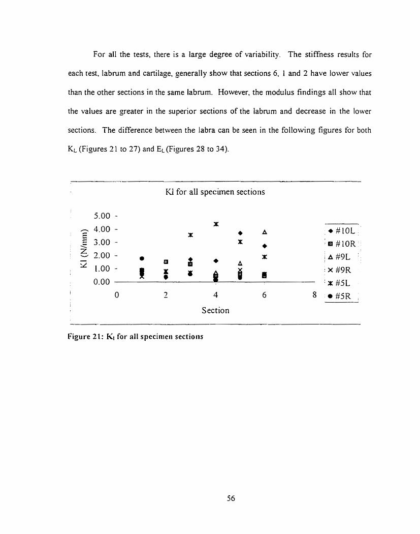
For al1 the tests. there is a large degree of variability. The stiffness results for
each test. labrum and cartilage, generally show that sections 6. 1 and 2 have lower values
than the other sections in the same labrum. However. the modulus findings al1 show that
the values are greater in the superior sections of the labrum and decrease in the lower
sections. The difference between the labra can be seen in the following figures for both
KL (Figures 2 1 to 27) and EL (Figures 25 to 34)-
KI for al1 specimen sections
1 O 2 4 6 8
Section
Figure 21: KI for al1 specinieii sections
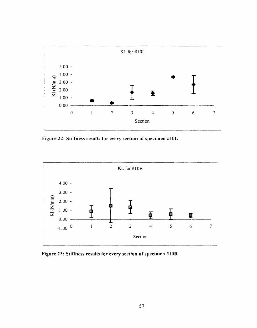
KL for $1 0L
O 1 - 7 3 4 5 6 7
Section
Figure 22: Stiffness results for every section of specinien #10L
KL for #IOR
1 Section
Figure 33: Stiffriess results for every section of specinieii #LOR
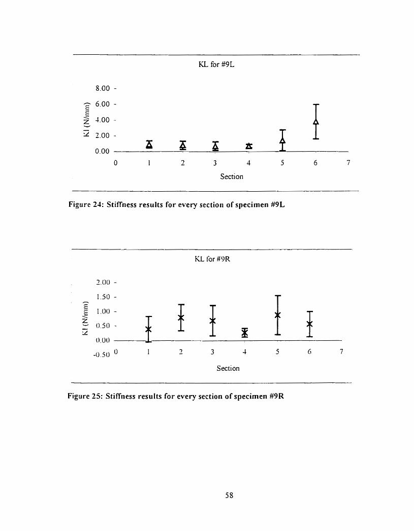
KL for g9L
Section
Figure 21: Stiffiiess results for every section of specimen M L
KL for #OR
O 1 3 -0.5 O - 3 1 5 Ci 7
Section
Figure 25: Stiff~iess results for every section of specimen #9R
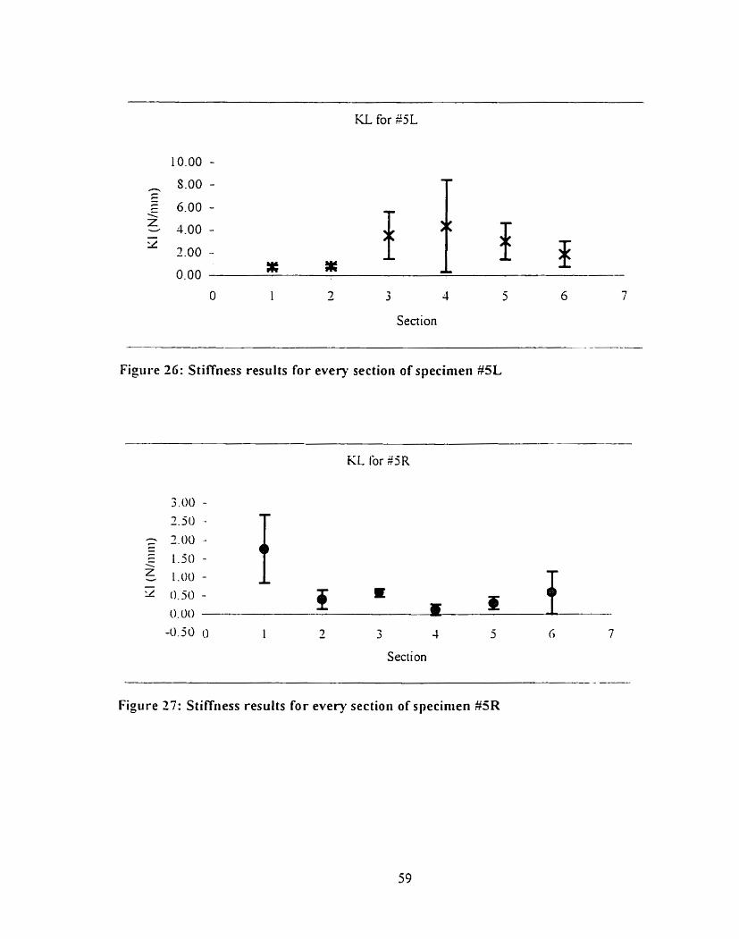
3 4
Section
Figure 26: Stiffness results for every sectioii of specimen #5L
Section
Figure 27: Stiffness results for every section of specinien #SR
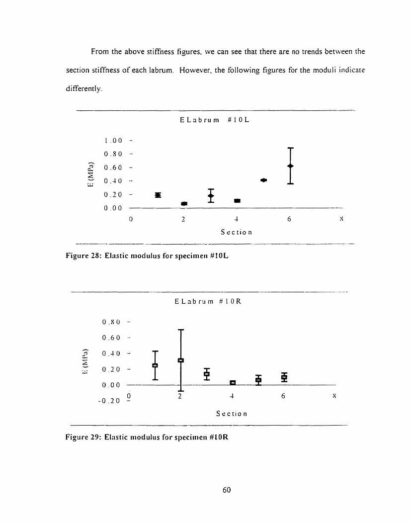
From the above stiffness figures. we can see that there are no trends between the
section stiffness of each labrum. However. the following ti, wres for the modtili indicare
differently.
S e c t i o n
Figure 28: Elastic niodulus for specinieii #l OL
S e c t i o n
Figure 29: Ehstic riiodulus for speciiiieri #LOR
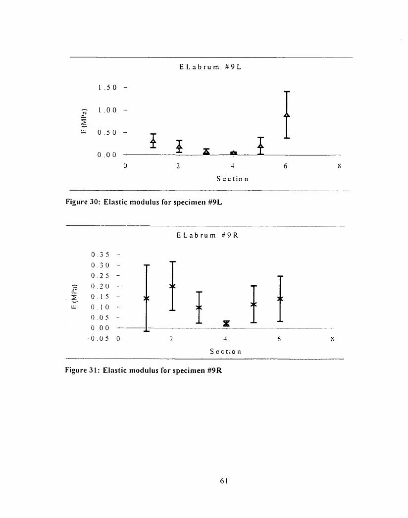
S e c t i o n - - --
Figure 30: Elastic itiodulus for specinieii #9L
Figure 31: Elastic niodulus for specinien #9R
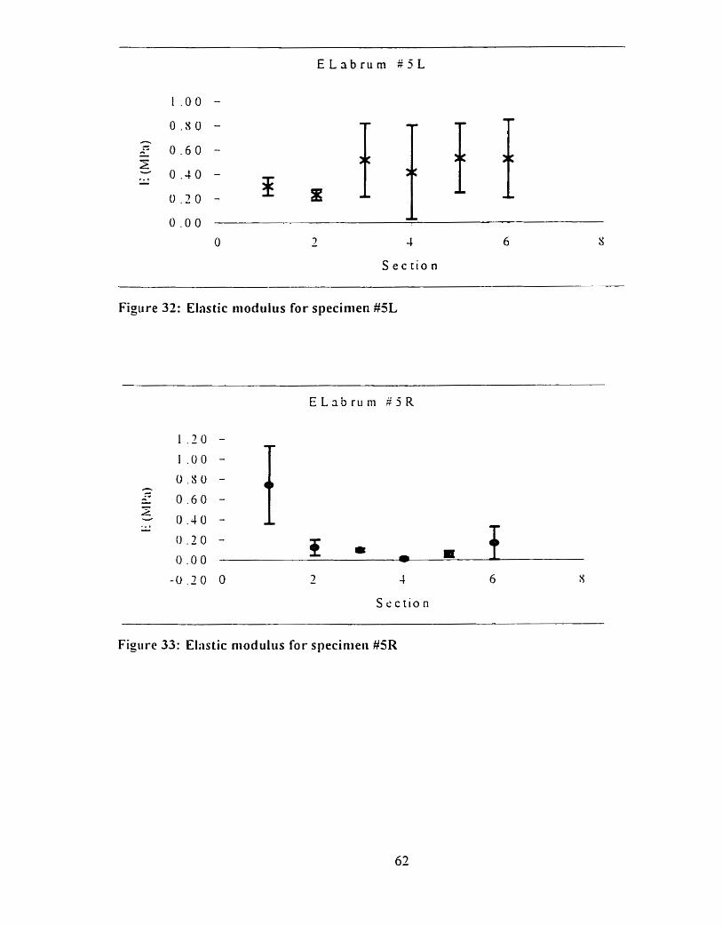
Figure 32: Elastic modulus for specinien #5L
S e c t i o n
Figiire 33: Eliistic niod ultis for specinieii #5R
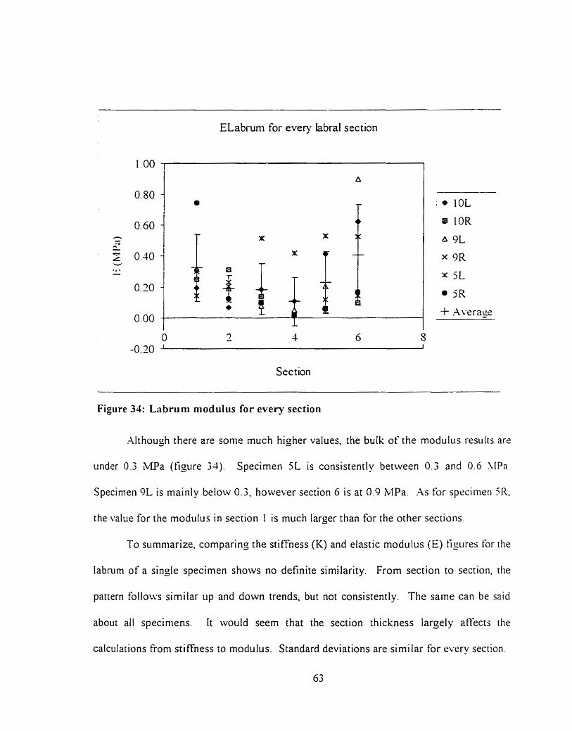
ELabrum for every labral section
Section
Figure 34: Labruni niodulus for every section
Although there are some much higher values. the bulk of the modulus resulrs are
under 0.3 ;LIPa (figure 34). Specimen 5L is consistently between 0.3 and 0.6 \ [Pa.
Specinieii 9L is mainly below 0.3, however section 6 is at 0.9 MPa .As for spccinieii 5R.
the value for the modulus in section I is much larger than for the other sections.
To surnniarize. comparing the stiffness (K) and elastic modulus (E) figures for the
labmm of a single specirnen shows no definite similarity. From section to section. [lie
pattern follows similar up and down trends. but not consistently. The same can be said
about ail speciniens. It would seern that the section thickness larçely atfects the
calculations €rom stiffness to modulus. Standard deviations are sirni lar for every section,
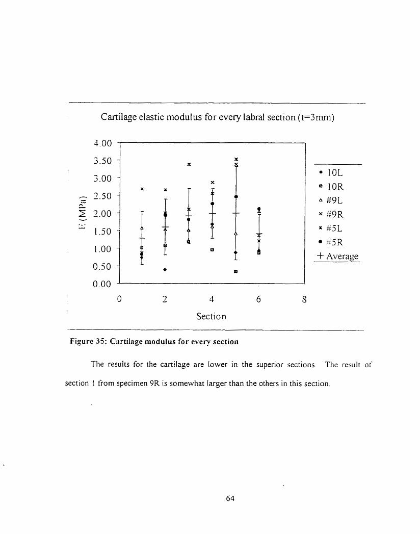
Cartilage elastic modulus for every labral section (t=3mni)
O - 7 4 6 S
Section
Figure 35: Cartilage niodulus for every section
The results for the cartilage are lower in the superior sections. The res~ilt of
section I from specimen 9R is someivhat larger than the others in this section.
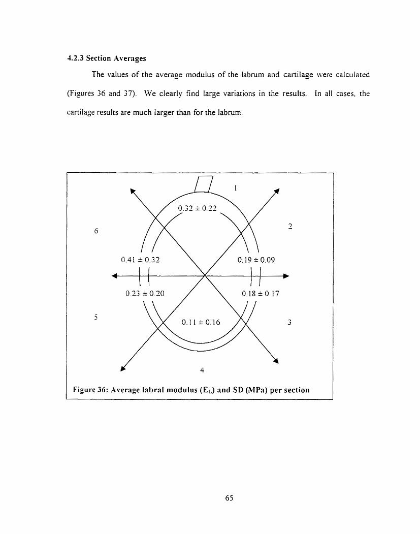
4.2.3 Section Avernges
The values of the average modulus of the labrum and cartilage were calculated
(Figures 36 and 37). We clearly tind large variations in the results. In al1 cases. the
cartilage results are much larger than for the labrum.
Figure 36: Average Iabral modulus (EL) and SD (MPa) per section
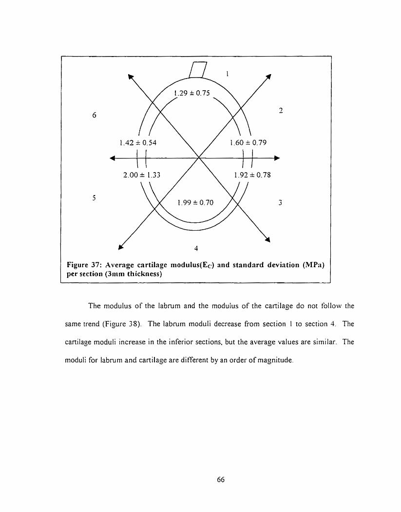
The modulus of the labrum and the modulus of the cartilage do not follow the
same trend (Figure 38). The labium moduli decrease from section I to section 4. The
cartilase rnoduli increase in the inferior sections. but the average values are similar. The
moduli for labmrn and cartilage are different by an order of magnitude,
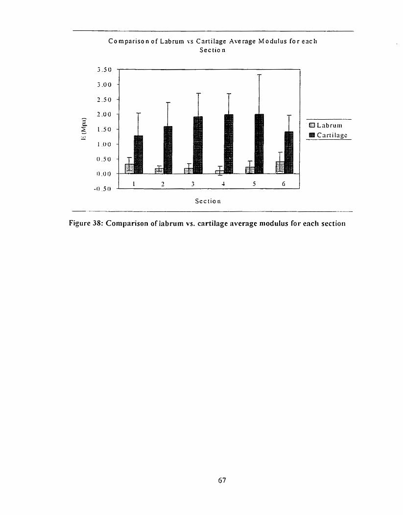
C o mpar i so n o f Lnbruin YS Cartilage Average M o d u l u s f o r each Sec tio n
Sec tio ri
Figure 38: Corn parison of labrurn vs. cartilage average niodulus for each sectioii
4.2.4 Statistical Analysis.
An hVOVA was performed on the labrum and cartilage stiffness and modulus
results to veriS if the results sarisfied the nul\ hypothesis that the samples corne from the
sarne population. Results for both the [abmm and cartilage showed variability between
secrions. However, the pattern was consistent between labra. Al1 AiSOVA were
periorrned with a 95% confidence level. A11 power test were done to find one standard +
deviation difference between the rneans.
The inter-section AïOV.4 for the labrum results. using the stiffness and moduliis
results showed that at least one section was significant different. This test had a power of
0 . 6 3 . As for the cartilage stiffness and modulus results, the inter-section Ab!OV.A.
calculated based on the stithess and modulus results, showed that at least one section
was significantly different. This test had a power of 0.638.
However. the inter labra ANOVA found that there were no significant
differences between labral moduli. This test had a power of 0.645 to find one standard
deviation difference between the means. As for the cartilage inter labra Aii0V.A.
computed usin% the averajed moduliis results, showed no signi ficant differences bet wern
labral nioduli. This test had a power of 0.437.
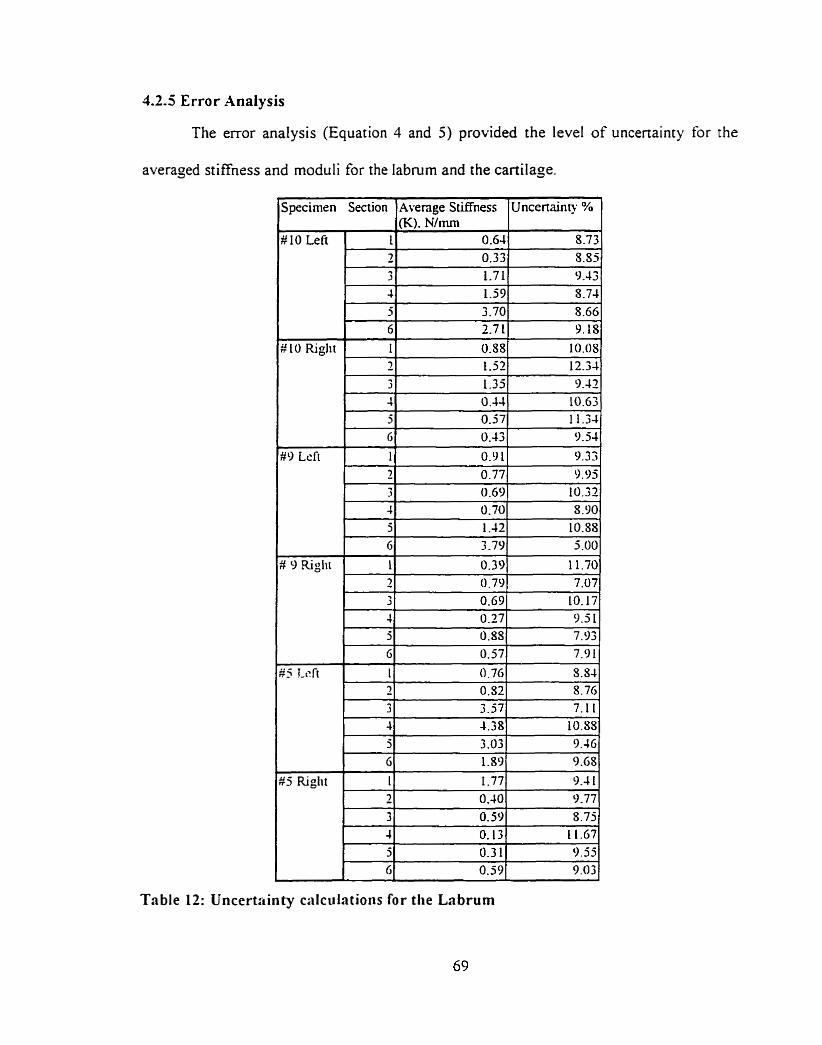
4.2.5 Error Analysis
The error analysis (Equation 4 and 5) provided the level of uncenainty for the
averaged stiffness and rnoduli for the labnirn and the cadage.
J ~ ~ e c i r n e n Section l ~ v e n ~ e Stiffness I~ncenainty % 1
#9 Lcft 1 1 I 9.331
Table 12: Uncertctinty calculations for t h e Labrum
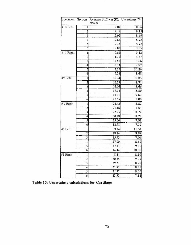
Table 13: Uncertrinty cnlciilations for Cartilage
Uncertainties ranged from 5 to 12 % for the stiffness and I 1 to 16% for the
modulus of both tissues. This levei of uncertainty shows that the variabiliry is likely to
be due to the sample and not testing emors.
These calculations indicate errors \ 1 to 16% for the modulus of the labrum.
Howe~er for the labrum. the error between the thickness used during the calculations to
the tnie thickness could add nearly 100% error for the thicker sections (6. 1 and 2 ) . Since
Equation 3. (E = stiffness s tissue thickness / area) is proponional to the thickness of the
tissue. then the error on the tissue thickness will directly translate into an error in the
rnoduliis. Therefore. the modulus values should only be an indication of the range of the
modulus. The modulus results are in the correct order of magnitude.
Chapter 5: Discussion
5.1 Introtlrt ction
The calculations used to obtain the elastic moduli used nominal thicknesses for
the labrurn and for the cartilage. For the labrurn, the margin thickness of the section was
used knowing that the thickness at the test site was less. By doing this. we could not _jet
the true material property. instead. we obtained a representative approximation of the
rnodulus and an indication of the role of the tissue thickness.
.As for the cartilage. the nominal 3-mm thickness was an appropriate assuniption
for tissue thickness based on previous studies. This provided a better approsimation of
the eiastic modulus.
The results of this research show that there are significant diferences ii i tlir
compressive response in the different sections of the labrum. It was established that ille
results could have been atfected by many complications before and durin2 the testing
The injuries to the tissue prior to testing could have changed the propenies or the overail
level of resistance it coiild provide. Funhermore, the bone chipping could have
weakened the substrate, thus iiot providing the appropriate backing. In addition. it \vas
shown that the labrum was aftècted by the thickness of the tissue since the niodiili resulrs
for the labium were proponional to the tissue thickness. Results froin stiffness tests
showed that there was a definite difference in the compressive resistance of each section.
This chapter will explain the results for each section.
Specimens used in this research were al1 elderly people who had donated their
bodies to science. The ages of the three cadavers ranged fiom 75 to S 9 and were not
representative of t he overall population.
The specimen dimensions confirm most of the findinjs from Howell and Galinat
(1988). The labral thickness measurements (Table 5) show that for al1 specimens. the
superior sections are thicker and that thicknesses decrease towards the inkrior sections
Thickness ditferences between the labra of the rijht and lefi arrn of a single
cadaver were noted. The dominant arm labmm was usually thicker in aIl the sections. In
addition, tliere was more fatty tissue attached to glenoid rim of the cadaver's non-
dominant arm. Finally. the dominant arm labruni was çenerally more conformant to rhe
radius of curvature of the humeral head.
Large labral thickness differences were noticed between sections. Section 1 had a
nearly constant thickness. 1 1.17 1.69mm and was the thickest. The biceps tendon hrad
estruded in a l l cases from this section and added compressive resisrance. Vanysricss
(1994) found that in al1 tested speciniens, approximately 50% of the biceps tendon arosc
directly from the superior labmm with the remainder attached to the supraglrnoid
tubercule. The biceps tendon mainly oriçinated from the posterior ponion of section I in
more than half of the specimens in his study. On close examination. szction 1 appeared
to be a very compliant materiai. Section 2 was a compliant tissue. on average 7.S6 =
I.3Omm thick. The thickness of the tissue steadily increases towards section 1 in this
section. Section 6 completes the superior portion of the labrum. Morphologically, it is
comparable to section 2 . The thickness of this section averaçed 7.91 = O79mni.
Sections 3 and 5 are the tissue transition sections. The sofi meniscal like tissue
became cartilaginous. Large variances in the response and thickness were espected and
seen in this region. Section 5 was a site of fatty tissue deposit on the glenoid rirn for two
labra. The average thickness of section 3 was 4-05 * 0-SOmm and 44s = 1.04mm for
section 5.
Section 4 was, by touch, a cartilaginous tissue with an average thickness of 2.3 9 =
0.39mrn. There was little thickness variation.
.As aforementioned. the superior section was a thick cornpliant tissue and the
inferior section is a thinner cartilaginous material. The medial anterior-posterior sections
averaged 6.07 È 2, l0rnm. This supports the results from Howell and Galinat ( 1 9S9) for
the anterior-posterior socket depth of 5 mm. However, the medial superior-inkrior
thickness differences ranginç from 7.39 i 0.39 mm for the inferior portion to 1 1.71 =
1.79 mm for the superior portion. can hardly be associated with the overall siiperior-
inferior 9-mm socket depth claimed by Howell and Galinat. This would be valid if only
the superior ponion was used for this statement. The concavity of the jienoid articular
surface in the superior-inferior direction did not seem to be able to accoiint for suc11 a
large difference. A larger sample size could have shown different results.
5.3 Specinr en observnb/e injuries
Possibly due to the age of the cadavers, injuries and tissue damage was found on
mosr specimens (Table 7). Cadaver # l O , lefi and right Iabra had more injuries than rhe
other specimens. closely followed by cadaver # 9. Cadaver # 5. the only male and
youngest subject. had fewer injuries. A larger sample size could have confirmed or
rejected the conclusions that sex and age are factors that influence the amount of injury
found in the Iabrum.
The most common tissue damage was degeneration. Sections 4. 5 and 6 revealrd
such tissue damage (Table 8). Lt would therefore seem that. in the specimens used in this
study, degeneration was limited to the inferior and posterior sections.
Sections 2 and 4 had siirt'ace tears to the tissue. Srirtàce tears can be described as
small lacerations in the tissue.
Specimen # 9 riçht had a SLM lesion in section 2; while specimen 25 lefi had a
small bucket handle tear (SLAP) in section 7. Specin~en # 5 lefi also had a cliipped bone
(bonr backing was broken). apparently held in place by only the labral tissue.
Most injuries occurred in the posterior superior sections. This is contrary to the
findings of Green (1995) who states that injuries occur mostly in the superior anterior
section. No esplanation can be çiven to explain these frequent posterior occurrences.
Hoivever. as we would espect. injuries clearly occurred more frequently in the superior
sections.
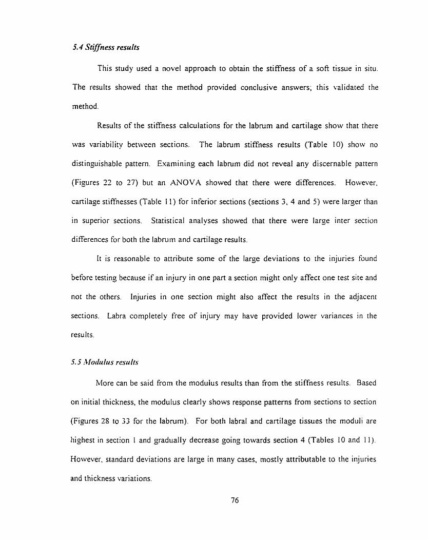
5.4 Stifiness results
This study used a novel approach to obtain the stiffness of a soft tissue in situ.
The results showed that the method provided conclusive answers; this validated the
method.
Results of the stiffness calculations for the labmm and cartilage show that there
was variability between sections. The iabrum stiffness results (Table 10) show no
distinguishable pattern. Examining each labrum did not reveal any discernable pattern
(Figures 23 to 27) but an ANOVA showed that there were differences. However,
cartilage stiffnesses (Table 11) for inferior sections (sections 3, 4 and 5) were larger than
in superior szctions. Statistical analyses showed that there were large inter section
differences for both the labnim and canilaje results.
I t is reasonable to attribute some of the large deviations to the injuries tbund
before testing because if an injury in one part a section might only affect one test site and
not the others. Injuries in one section might also affect the results in the adjacent
sections. Labra cornpletely free of injury rnay have provided lower variances in the
results.
More can be said from the modulus results than from the stiffness results. Based
on initial thickness, the modulus clearly shows response patterns from sections to section
(Figures 2s to 33 for the labrum). For both labral and cartilage tissues the moduli are
highest in section 1 and gradualiy decrease çoing towards section 4 (Tables 10 and I I ) .
However. standard deviations are large in many cases. rnostly attributable to the injuries
and thickness variations.
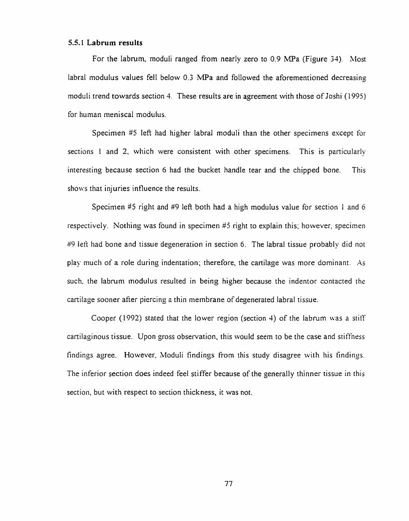
5.51 Labrum results
For the labrum, moduli ranged From nearly zero to 0.9 MPa (Figure 34). Most
labral rnodulus values fell below 0.3 W a and followed the aforementioned decreasins
moduli trend towards section 4. These results are in agreement wirh those of Joshi (1995)
for human rneniscal modulus.
Specimen $5 lefi had higher labral moduli than the other specimens escept for
sections 1 and 2, wliich were consistent with other specimens. This is panicularly
interestin; because section 6 had the bucket handle tear and the chipped bone. This
show that injuries influence the results.
Specimen $5 right and C9 lefi both had a high modulus value for section 1 and 6
respectively. Nothing was found in specimen #5 right to explain this; however, specimen
$9 leti Iiad bone arid tissue degeneration in section 6. The labral tissue probably did not
play rnucli of a roie during indentation; therefore, the cartilage was more dominant. .As
such. the labium modulus resulted in being higher because the indentor contacted the
cartilage sooner afier piercing a thin membrane of deçenerated labral tissue.
Cooper (1992) stated that the lower region (section 4) of the labrum was a stitf
cartilaginous tissue. Upon gros observation. this would seem to be the case and sriffness
findings agree. However, Moduli findings from this study disajree with his findings.
The inferior section does indeed feel stiffer because of the generally thinner tissue in this
section, but with respect to section thickness, it was not.
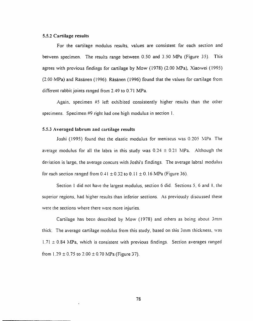
55 .2 Cartilage results
For the cartilage modulus results, values are consistent for each section and
between specimen. The results range between 0.50 and 3.50 MPa (Figure 3). This
agrees with previous findings for cartilage by Mow (1978) (2.00 iMPa), Xiaowei (1995)
(2.00 MPa) and Rasanen (1996). Rasanen (1996) found thar the values for canilage from
different rabbit joints ranjed from 2.19 to 0.7 1 MPa.
Again. specirnen 45 lefi exhibited consistently higher results than the other
specimens. Specimen $9 right had one high modulus in section 1 .
5.5.3 Averaged labrum and cartilage results
Joshi (1995) found that the elastic modulus for nieniscus was 0.205 YLPa. The
average modulus for al1 the labra in this study was 0.24 ir 0.11 h,lPa. Xlthough the
deviation is large, the average concors with Joshi's findinçs. The average labral modulus
for each section ranjed from O3 1 k 0.32 to O. I 1 i: O. 16 iMPa (Figure 36).
Section 1 did not have the larçest modulus, section 6 did. Sections 5. 6 and i . the
superior regions. had higher res~ilrs than inferior sections. .As previously discussed these
were the sections where there were more injuries.
Cartilage has been described by Mow (1978) and others as being about 3mni
thick The average cartilage modulus from this study. based on this 3mm thickness, \vas
1.71 ? 0.54 hIPa, which is consistent with previous findinçs. Section averages ranged
from 1.29 k 0.75 to 2.00 i 0.70 W a (Figure 37).
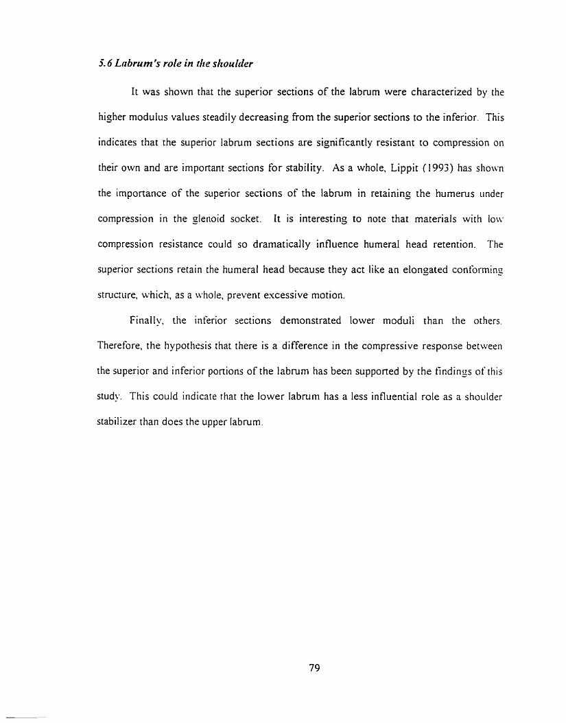
5.6 Lnbrurn 's role in the shoukder
It was shown that the superior sections of the labrum were characterized by the
hizhrr modulus values steadily decreasing from the superior sections to the inferior. This
indicates that the superior labmm sections are significantly resistant to compression on
their own and are important sections for aability. As a whole, Lippit (1993) has show
the importance of the superior sections of the labmm in retaining the humerus under
compression in the gienoid socket. It is interesting to note that materials with lori-
compression resistance could so dramaticall y influence humeral head retention. The
superior sections retain the humerai head because they act like an elongated conforming
strucrure. which, as a whole, prevent excessive motion.
Finaily, the inferior sections demonstrated lower moduli than the others.
Therefore, the hypothrsis that there is a difference in the compressive response betwetn
the superior and inferior portions of the labrurn has been supponed by the Rndings of this
study. This could indicate rhat the lower labrum has a less influential role as a shorilder
stabilizer than does the upper labrum.
5.7 Cot~zpnriron of the cnrtilnge finditzgs tu previous studies
Using a nominal cartilage thickness of h m , the maximum modulus was
calculated to be 2.00 ma. which was slightly lower than the results from previous
studies on animal and human lower limb cartilage. This could indicate that the
canilaginous sections of the =lenoid labnirn have lower compressive resistances than the
canilage found in the animal estremities. The results from Rasanen ' s study with rabbit
canilage shows large variances. However, human and rabbit cartilage could be ver!.
ditkent between each other.
The findings of this study match the results from previous results for liiiman and
animal cartilage. This validates the mode1 of using the anicular cartilage as the second
tissue under compression. and treating the underlying bone as rigid.
5.8 Effect ofcotnprcssii~r rcsponsc vnrintions on possible injury occurrence
.As a seneral staternent. different compressive responses s hould affect t5e
occurrence of injuries. Studies have shown that injuries mostly occur in tlie siiperior
portion of the labrum. Based on their thickness, their importance in retaining the humeral
head in place and their low rnodulus cornpared to other structures. this srudy would arsue
that they are more susceptible to be damaged by compressive loads. SLAP lesions
should be espected in shoulder related injuries caused by anterior posterior translation of
the humeral head. The fact that Kohn (19S7) found many cases of injurrd labnim in his
study of 106 cadavers demonstrates the ease of gettinj such injuries. However.
destructive testing would have been required to clearly demonstrate this point.
5.9 Error crrzrz!,.sis
During the course of the testing period. possible sources of error ivert: noted. In
some instances. there were labral tears and bone breakaçes during indentation.
Xlthougli bone breakape would only occur at the end of a test. during tlie
averaging procrss of the three trials. an error could have resulted if this section of data
had been used in the calculations. However, as was done durin; the analysis, removiiig
the bone break-off portion of the data rninimized the error. Nonetheless. it was stitl
possible that the data could have been affected before the actual break.
The etfect of creatin~ a labral tear during a test would influence the test
perfornied near the point of tearing. Althouçh the tears were usually contained to the
point of indentation, it could have an effect on the surrounding tissue. The attachment
point of the labrum is thus generally weakened, and the surrounding labral stmctiire
stretc hed.
An important point to reiterate is the effect of tests being perfonned near the
prwious indentation point. Cornpressing a tissue does noi only etfect the tissue direct1 y
under the indentor but also the surrounding tissue. Near the indentor bounda~ . the
effects were unrecoverable. but further away from the indentor boundary the effects were
minimized and neglected. Each section had an arc length of about 15-2 cm. In each
cases. one to two indentor diameters were lefi as space between indentation sites ro
minimize the effects. There was a j-minute recovery time between indentations to help
rnininiize the effects of the previous indentation to the next test area.
The error analysis showed experimental errors that were much smaller than the
resulr standard deviations. whic h were calculated from the averagi ng process across
specimens. Errors on the stitl-ness results ranged from 5 to 12% of the stiffness. Since
the error on the thickness used in the modulus equations could be as high as 100%. the
same error is applicable to the rnoduius. From the stiffness results. niuch of the
variability is attributable io the population.
Chapter 6: Summaw
This study represents the first examination of the compressive characterist ics of
the labmm of the shoulder. The method used was a novel testing procedure for obtaining
in situ material properties. It was one of objectives of this work to determine if there was
a material difference in the structural response between the superior and inferior portion
of the labrum. The ditferences were evaluated by assuming a piece-wise linear elastic
model.
The indentation tests were perforrned 3 times, if possible. in each section to
provide average load-compression curves. The load increase was performed i i nt i l t hr
indentor rrached the bone surface. The load increased as a steep ramp function peakiny
within 200 rns. The instron was set at a strain rate of 200mrn/min. There was 5-minure
recovery period between each indentation. Testing was performed on an elderly
population with some tissue degeneration. Embalmed specirnens were üsed due to lack
of a\-ailable fresh cadavers.
I t ivas espected that this study would help define the mechanical role of the
labnim and the limits to its resistance to the humeral head forces.
Cooper (1992) described the inferior portion of the labrum as a weil-rounded
structure firmly attached to the glenoid rim and the superior portion as a loosely attached
tnangular material. m ai th ou@^ gross observation of the tissues would agree with these
statements, testins results showed that the inferior sections were more compliant in
compression.
It was also found that there were thickness and size differences between the
dominant and non-dominant arm of a cadaver. The dominant arm had thicker margin
labral tissue, but the inner facer of the labrum was more conforming to the curvaturc of
the hunieral head.
The study demonstrated significant differences between the compressive resporiss
of the superior and inferior portions of the labrum. The moduli for the superior sectioris
were yeater than for the inferior section.
A n important ftndins was t h e similarity of the modulus results from comparable
anterior and posterior sections of the labrum. This contirrned that the likeliliood of
injuring the anterior and posterior portions of the labrum should be equivalent under
similar loading condit ions.
The findings nerded to b r comparable with previous studies to be tmly of value.
Using a known average thickness for cartilage. the results ranged froni 3.00 r O 70 to
1.29 = 0.75 ma. These results ayree with previous studies.
This study found the rriodulus of the labrurn to be in the range of 0.41 i 0 32 to
0.1 1 I O. 17 W a which agree with Joshi ( i 995)'s findings for human rneniscus.

It is the belief of the researcher that t he higher resuits fiom this study are caused
by the use of ernbalrned cadavers. Linde (1994) found that trabecular bone modulus \vas
increased by a few percent when embalmed. This could explain some of the differences
found for the labnirn and cartilage found by this study.
This study did not unequivocally prove that the glenoid /abmm has a role in
shoulder stability. It did, however. manage to bring fonh and confirm some important
findings about the labmm and validate the testing procedure.
I t ivould be interest ing to investisate the labrum different ly. Performing confined
compression tests would establish the precision of indentation testing and confirm or
refute the findings of this stildy.
i t would be beneficial to esamine the difference between embalmed and fresh soti
tissue sincr no previous work \vas found on the subject. X larçer saniplc sizc n-ould
certainly increase the statistical power of the tests.
A rnorphological study assessing differences between dominant arm and non-
dominant arni characteristics could be done, to investigate the differences which were
noted.
Obtaining the value tnie propenies of the glenoid labrum rvould be useful in
creatin; a proper finite eleinent inodel of the glenohumeral joint. which woiild have valrie
in designing replacement arthroplasties for the shoulder.
References
.hglin C., Tolhurst P., Wyss L'.P.. Pichora D.R.: blechanical Propenies of Glenoid Cancellous Bone. Apps Medical Research Centre, Kingston General Hospital. Draft. 1997
.hglin. C, Wyss. U: Biomechanics of the Shoulder Joint: .A Repon Prepared for Sulzer Medical Technoloçy Ltd.. Dept. of Mechanical Engineering. Queens University, 1995
k c i o RA, Pierre PS: Acute Shoulder Dislocation: Indications and Techniques for Operative iManagement. Clinics in Sports Medicine 14 (4): 729-38. 1995
Askew M.. Mow VC: The Biomechanical Function of the Collagen Fibril Ultrastructiire of anicular Cartilage, Journal of Biomechanical Engineerinj, Vol. 100, 105- 1 15, 197s
Athanasiou K . A . Niederauer G.G.. Schenck R.C. Jr.: Biomechanical Topography of Hunian Ankle Cartilage. .-\iinals of Biomedical Engineeriq. Vol. 23, 697-704. 1995
Baker MA: Shoiilder Replacenwnt Reconstruction: Pomona Valley Comrnunity Hospital. 1987
Bankart B A S : The Patholo~y and Treatment of Recurrent Dislocation of the S lioiilder Joint, British bfedical Journal. No. 76, 33-39, 193s
Barlett CS. Et al: Gunsliot Wounds to the Shoulder. Onhopedic Clinics of Nonh America 36(1): 37-53, 1995
Blasier. R. et al: Anterior Shoulder Stability: Contribution of Rotator Cuff Forces aiid the Capsular Ligaments in a Cadaver Model, Journal of Shoulder Elbow Surgery. Vol. l (5). 141-150, 1992
Bowen et al: Role of the Inferior Glenohurneral Ligament Comples i n l i rni t ins Inferior Translation of the Glenohunieral Joint, 3 8'" h n u a l Meeting. Onhopedic Researc h Society, Washington DC, p.497, 1993
Bowen et al: The Effect of Joint Compression on Stability ofthe Glenohunieral Joint. 3s"' Annual Meeting, Orthopedic Society. Feb 17-20. Washington, DC, 1992
Bradley JP et al: The Biomeclianics of the Throwing Shoulder, Perspective of Onhopedic Surgery, Vol. l(2): 49-59, 1990
Breault-Janicki MJ: Mechanical and Histoloçical Characteristics of Rheurnatoid Wrist Tendons and Ligaments. Ph.D. Thesis, Department of Mechanical Engineering. Qiieen's University at Kingston, 1995
Brems JJ: Degenerative Joint Disease of the Shoulder. Nicholas JA, Hershman EB. Eds. The Upper Extrernity in Spon Medicine. Vol. 1, C. V. Mosby Comp., 237-252, 1990
Bulloujh PG, Munuera L. Murphy J, Weinstein h: The Strengh of the Menisci of the Knee as it Relates to Their Fine Structure, Journal of Bone and joint Surgery. 5ZB. 564. 1975
Butler DL, Grood ES, Noyes FR, Zernicke RF, Brackett K: Effect of Srmcture and Strain Measurement Technique on the Material Properties of Young Human Tendons and Fascia, Journal of Biomechanics, Vol. 17 (S), 579-596, 1984
Caputy GG. Antonyshyn OM: Bendinj Mechanics of Bone Grafis: . i n esperiniental Study. The Journal of Craniofacial Sursery. Vol. 3(?), 50-54. IW:!
Cassin J.: The Effect of Low Temperature Storage on the Viscoelastic Properties of Rat Tai1 Tendons, M. Sc. Thesis. Department of Mechanical Engineering, Queens' University at Kinston, 1997
Cooper, DE, Xrnoczky, O'Brien SJ. Warren RF, DiCarlo E, Allen .=\A: -4natoniy. Histology. Vascularity of the Glenoid Labrum. The Journal of Bone and Joint Sursery. V01.74-A ( l ) , 156-52, 1993,
Cordasco, FA. , Steinmann S., Flatow E.. Bigliani L.: Arthroscopie Treatment of Glenoid Labral Tears. The Anierican Journal of Sports Medicine. Vol2 1 (3). 325-430. 1993
Counias M. Waite FU, Goss TP. Ferrari DA, Kanzaria P, Pappas .LM: CT and U R Evaluation of the Labral Capsiilar Ligarnentous Complex of the Shoulder. .UR: 15s. 59 1 - 7, 1993
CrandaIl, S.H., Dahl, N.C., Lardner, T.J.: An Introduction to the Msthanics of Sdids. Second Edition, iLIcGraw Hill, Toronto, 1975
Crawford CJ, Laberge M. .Men BL Jr., Powers DL: Growtli Profiles and Artic~~lar Cartilage Characterization in a Goat Mode1 of Leçg-Calve-Perthes Disease: Journal of lnvestigat ive Surgery, Vol. S(6). 3 9 1-408, 1993
Curl LA, Warren RF: Glenohumeral Joint Stability, Clinical Orthopaedics and Related Research, Vol. 330. 54-65, 1996
Davidson LK: Diniensional and Geometrical Characteristics of the Glenohiimeral Joint. M. Sc. Thesis, Departnient of Surgery, Queens' University at Kinston, I W O
Devries S.: A Thrre-Diniensional Finite Element Stress Analysis of the Glenoid witli and without a Total S lioulder Anhroplasty Component, M. Sc. Thesis. Depanmerit of Mechanical Ençineering, Queens' University at Kinston, 1995
Eberhardt, A., Lewis. L.. Keer, L.: An Analytical Mode1 of Joint Contact. Journal of Biornechanical Engineering, Vol. 1 12, 407-4 13, 1990
Edelson JG: Bony Changes of the Glenoid as a Consequence of Shoulder Instability. Journal of Shouider and Elbow Surgery, Vol. 5(1), 393-298, 1996
Ellenbecker TS: Rehabilitation of Shoulder and Elbow Injuries in Tennis Players. Clinics of Sport Medicine 14(1): 87- 1 10, 1995
Engin & Chen: Statistical DataBase for the Biomechanical Propenies of the Hunian Shoulder Cornplex-1 : Kinematics of the Shoulder Cornplex. Journal of Biomechanical Engineering, Vol. 1 SO, 2 15-21. August 56
Ferg~ison S. ( 1996), Personal communications
Fleisis GS, Andrews IR, Dillman CJ. Escamilla RF: Kinetics of Baseball Pitching with implications about Injiiry Mechanisms, The American Journal of Sports Medicine. \'ol. 23(2). 333-239, 1995
Friedman RJ: Glenohumeral Instability. Journal of South Onhopedic .-\ssociation. 4 3 . 1 S3- 199, Fall 1995
Frieman BG et al: Rotator Cuff Disease: A Review of Diagnosis, Pathophysiolog. and Current Trends in Treatment. Archives of Physical Medicine and Rehabi l itation. No. 75. 603-9, 1994
Grauer ID. Paulos LE. Smutz WP: Biceps Tendon and Superior Labral Injuries. The Journal of Arthroscopic and Related Surgery, Vol. S(4), 3SS-497, 1992
Green UR, Chrisyensen W: Arthroscopic Bankart Procedure: Two-to-tive k'ear Follow iip with Clinical Correlation to Severity of Glenoid tabral Lesion, The American journal of Sports Medicine. Vo1.23 (3), 276-2s 1, 1995
Haberrneyer P and Schuller U: Signitïcance of the Glenoid Labmrn for Stability of the Glenohumeral Joint. An Esperimental Study, Unfallchirurç Vo1.93 ( 1 ). 19-26. 1990
Hale J.E., Ruden M. J., Brown T.D.: Indentation Assessment of Biphasic blecliniiical Propeny Deficits in Size-Dependent Osteochondral Defect Repair. Journal of Biomechanics., Vol. 26 (1 1), 13 19-1325, 1993 Hall SI: Basic Biomechanics. St. Louis. Mosby-Year Book. Inc., 1995
Hara H. Ito S. lwasaki K.: Strençth of the Glenoid Labrum and Adjacent Shoulder Capsule, Journal of Shoulder and Elbow Surgery, Vol. 5(4), 263-8, Jul-Aug 1996
Harada Y.. Wevers H.W., Cooke T.D.V.: Distiibution of Bone Strength in the Proximal Tibia. The Journal of Arthroplasty, Vol3 (2). 16% 175. 198s
Han-yman & al. 1992: Laxity of the Normal Glenohumeral Joint: X Quantitative Ln-vivo Assessment. Journal of Shoulder Elbow Surgery, vol. 1 (2). March-April 1992
H a q m a n & al.: The Effect of ..\rticular Conformity and the Size of the Humeral Head Component on Laxity and the Motion afier Glenohurneral Arthroplasty. The Journal of Bone and Joint Surgery, Vol. 77A (4). April 1995
Hanyman DT. Sidles JA, Clark JM, McQuade KJ, Gibbs TD. Matsen FA: Translatiori of the Humeral Head on the Glenoid with Passive Glenohunieral motion, The Journal of Bone and Joint Surgery. vol. 7 2 4 . 13344343, October 1990
Haut RC, Little RW: A Constitutive Equation for Collajen Fibers, Journal of Biomechanics, Vol. 5 (5). 4-3-43 0, 1972
Hayes W.C., Keer L M , Herrrnan G.. Mockros L.F.: .A mathematical .Analysis for indentation tests of Articular Cartilage. Journal of Biomechanics. Vol. 5. 54 1-55 i , l971
Helrnig P. Sojbjerb JO. Sneppen O. Loehr IF, Ostgaard SE. Suder P: Glenohiirneral blovement Patterns After Puncture of the Joint Capsule: An Experiinental Study. Journal of Shoulder Elbow Surgery. Vol. 2(J), 209-1 15. 1993
Howell SiM, Galinat BJ, Renzi AJ, Marone PJ: Normal and Abnormal YIectianics of the Glenohunieral Joint in the Horizontal Plane. The Journal of Bone and Joint S u r p y . 227- 332,19SS
Howell SM, Galinat BJ: The Glenoid-Labral Socket. Clinical Onhopaedics and Related Research i%G, 123- 125.1 9S9
Hurley JA: Anatoniy of the Slioiilder. Nicholas J.4, Hershmnn EB, eds. The Upper Estreniity i n Spon Medicine. Vol. 1 :C. V. Mosby Comp.. 23-40 I99O
[toi & al: Scapular inclination and Inferior Instability of the Shoulder. 3s"' Aniiiial Meeting, Onhopedic Society. Washington, DC, Feb 17-20. 1992 Itoi, E. et al: Inferior Stabilizing Function of the Coracohumeral Ligament and the Rotator Interval Capsule. Combined Onhopedic Research Societies meeting. Nov 1995. San Diego. Cal.. P.; 1 I
Jenkins RB, Little RW: A Constitiitive Equation for Parallel-Fibered Elastic Tissus. Journal of Biomechanics, Vo1.7, 397-402, 1974
Joshi MD. Suh J-K.. hlanii T., Woo S. L-Y.: Interspecies Variation of Conipressivr Biomechanical Propenies of the Meniscus. Journal of Biomedical Materials Research. Vol. 29, 833-SIS, 1995
Karzel RP. Nuber G. Lautenschlager E: Contact Stresses During Compression of the Glenohumeral Joint: The Role of the Glenoid Labrum. Proc Inst Med Chicago. Vol 12. 63, 1989
Katoh T, Griffin W. Wevers HW, Rudan J: Bone Hardness Testins in the Trabecular Bone of the Human Patella, Journal of hhroplas ty Vol. 1 l(4). 460-5, 19%
Kim YT. Azurna H: The Nerve Endings of the Acetabular Labrum. Clinical Orthopaedics and Related Research, Vol. 330, 176-181, 1995
Koenecki S and Zschorlich V: The Nature of the Stabilizing Functions of the Skeletal Muscles. Journal of Biomechanics 27(2) 2 I5-X,l994
Koenecki S: Mechanism of Muscular Stabilization Process in Joints. Journal of Biomechanics 25(3 ) 23 5-45, tg91
Kohn Dieter: The clinical Relevance of the Glenoid Labrurn Lesions, The Journal of kthroscopic and Related Sursery. Vol. 3(4), 273-130, 1957
Kuniar W. Balasubramaniam P: The Role of Atmospheric Pressure in Stabilizing the Shoulder. The Journal of Bone and Joint Surgery. Vol.67-B(j).7 19-72 1.19S5
Lazarus MJ3, Sidles JA. Harryrnan DT, Matsen FM: Effect of a Chondral-Labral Defect on Glenoid Concavity and Glenohumeral Stability. The Journal of Bone and Joint Surgery. Vol.7S-A (1 ), 94- 102, 1996
LeVeau BF.: Biomechanics of Hurnan Motion. Philadelphia. W.B. Saunders Conip. . 1992
Linde F.: Elastic and Viscoelastic Propenies of Trabecular Bone by a Compression Testing Approach. Dan. Med. BLIII., Vol. 4 I(2). 1 19- 138, 1994
Lippitt S. Matsen F.: Mechanisms of Glenohumeral Joint Stability. Clinical Onhopnedics and Related Research, $39 1 , 20-8, 1993
Little R.B., Wevers H.W., Siu D., Cooke T.D.V.: A Three-Dimensionai Finite Elenieiit analysis of the Upper Tibia. Journal of Biomechanical Engineering, Vol. 108, l I 1 - 1 19, 1986
Longo C, Loredo R Yii J. Salonen D, Haghiçhi P. Trudeii D, Clopton P. Resnick D: MRI of the Glenoid Labmm with Gross Anatomic Correlation, Journal of Cornputer Assisted Tomoçraphy. Vol. 20(3), 487-495, 1996
Loredo R, Longo C. Salonen D. Yu J, Haghighi P. Trudell D, Clopton P. Resiiick D: Glenoid Labmm: bW with Histoloçic Correlation, Radiology Vol. l96( 1 ), 33-4 1, 1995
Maffet W. Gartsman GM. Moseley B: Superior Labmm-Biceps Tendon Comples Lesions of the Shoulder, The American Journal of Sports Medicine, Vo1.23(1) 93-98, 1995
Llak AF, Lai, WM, Mow VC: Biphasic Indentation of .Articular Cartilage-1. Theoretical halysis. Journal of Biomechanics, No. 20 (7). 703-7 14, 1987
LMallon WJ, Speer KP: Multidirectional Instability: Current Concepts, Journal of Shoulder Elbow Sursery. Vo1.4(1) Pan 1, 5464,1995
Meriam & Kraige: Engineering Mechanics. vol. 1 & 2. Wiley,Toronto, 1987 Messner K.. Gillquist J.: Prosthetic Replacement of the Rabbit Medial iLleniscus, Journal of Biomedical Materials Research, Vol. 27, 1 1 35-1 173, 1993
Mo\\- VC. .Amoczky SP. and Jackson D W Knee meniscus: Basic and clinical foundations. Raven Press. NY, 1992, 37-57
kloiv VC, Gibbs MC, Lai WM, Zhu WB. Athanasiou KA.: Biphasic Indentation of .Articular Cartilage-LI. A Numerical Algorithm and an Esperimental Stiidy. Journal of Biomechanics, No. 72 (8/9). S S S 6 1 , 1989
Mow VC, Kuei S. lai W.. Armstrong C.: Biphasic Creep and Stress Relasation of Articular in Compression: Theory and Experiments, Journal of Biomechanical Enzineering. Vol. 102. 73%. 1980
Nakabayashi Y.. Wevers H. W., Cooke T.D.V., Griffin M.: Bone strength and Histornorphornetry of the Distal Femur, The Journal of arthroplasty, Vol. 9(3). 307-3 15. 1994
Nigg B.M.: Biomechanics of the Musculoskeletal System. W . John Wiley and Sons. 1994
O'Brien SJ. Schwartz RE. Warren RF, Torzilli PA: Capsular Restraints to Anterior/Posterior motion of the S houlder. Onhop Trans, Vol. 12, 143. 19SS
Ogata. K.: Modern Control Engineering. Second Edition. Prentice Hall. Englewood Cliffs, NJ, 1990
Ozkaya N and Nordin M.: Fundarnentals of Biomechanics: Equilibrium, Motion and Deformation. Van Nostrand Reinhold pp. 108- 1 1 1, 199 1
Pagnani MJ. Deng X, Warren RF, Torzilli, Altchek DW.: Effect of Lesions of the Superior Portion of the Glenoid Labrurn on Glenohumeral Translation. The Jourrial of Bone and Joint Surçery. Vol. 77-A (7), 1003- 10, 1995
Pagnani, M.J. & Warren, R.F.: Stabilizers of the Glenohumeral Joint. Journal of Shoulder Elbow Surgery. 173- 190, May-June 1994
Rames RD. Karzel RP: Injuries to the Glenoid Labrurn Including SLXP Lesions. Orthopedic Clinics of North America, VoI.24(1), 1993
Rasanen T, Messner K: Regional Variations of Indentation Stiffness and Thickness of Normal Rabbit Knee Articular Cartilage.. Journal of Biomedical hlaterial Research. Vol.; 1(4), 5 19-24, 1996
Reeves B.: Experiment on the Tensile Strength of the Anterior Capsular Stnictures of the Shculder in Man. The Journal of Bone and Joint Sur~ery , Vol. 5OB (4). SjS-S65 , 196s
Saha AK: Dynamic Stability of the Glenohumeral Joint. Acta Orthop Scandinavicn. \d. 42,191, 1971
Sanjeevi 9 Somanathan N, Ramaswamy D: A Viscoelastic Mode1 for Collagen Fibers. Journal of Biomechanics, Vol. 15(3), 1 S 1-3, 1982
SokoloK L. : Elasticity of Aginj Cartilage. Federation Proceedings. 1039- 1095. 1966
Soslowsky LJ. Flatow EL, Bigliani LU, Mow VC: h i cu l a r Geomeiry of the Glenohumeral Joint. Clinical Ort hopaedics and Related Research, 2 S 5 . 1 S2- 1 90. 1992
Speer KP, Deng X, Borrero S, Torzilli PA, Altchek DA, Warren RF.: Biornechanical Evaluation of a Simulated Bankart Lesion, The Journal of Bone and Joint Siirger-y. Vol. 76-.A ( 12), 1 S 19- 1 S26.1994
Speer KP, Deng X. Torzilli P.A. Aitchek DA, Warren RF: Strategirs for an Anterior Capsu tar Shi fi of the S houlder, .A Biomechanical Cornparison. The American Journal of Sports Medicine. Vol. 23(3), 264-269, 1995
Speer KP.: h a t o m y and Pathomechanics of Shoulder Instability. Clinics in Spons Medicine, Vol. 14(4), 75 1-760, 1995
Spilker R. L.. Suh J.-K., Mow V.C.: A Finite Element Analysis of the Indentation Stress- Relasation Response of the Linear Biphasic Articular Cartilage, Journal of Biornechanical Engineering, Vol. 1 1 1 , 191-20 1. 1992
Suder PA, Houçaard K, Frich LH, Rasmussen OS. Lundorf E: Intraaniciilar Findings in the Chronically Painful Shoulder. A Study of 32 Posttraumatic cases.. Acta Onhoedic Scandinavia, No.65(3). 339-43, 1994
Sumner DR, Willke TL. Berziiis A, Turner TM: Distribution of Young's klodulus i n the Cancellous Bone of the prosimal Canine Tibia, Journal of Biomechanics, So. 27(S). 10%- 1099, 1994
Vangsness CT Jr., Ennis M., Taylor JG, Atkinson R.: Neural Anatorny of the Glenohumeral Ligaments, Labrurn, and Subacromial Bursa, The Journal of Mhroscopy and Related Surgery, Vol. 1 1, No. 2. 180- 184, April 1995
Vanosness CT Jr., Jorgenson SS, Watson T, Johnson DI: The Origin of the Long Head of The Biceps f?om the Scapula and Glenoid Labrurn. an hatorrtical Study of 100 Shoulders., Journal of Joint Surgery, No.76(6), 95 1-954, Nov. 1994
Video: Total shoulder .Arthorplasty Systern: Surgical Procedure with Pre and Post Operarion, Global. DePuy, 1994
LVarner J, Deng X, Warren RF, Torzilli Pr\. O'Brien SJ: Superioinferior Translation in the Intact and Vented Glenohumeral Joint., Journal of Shoulder Elbow Surgery, Vol. 2(2). 99-105, 1993
Warren W. Kornblatt IB. Marchand R: Static Factors Affecting Posterior Sliouldrr Stability. Ortho Trans. Vol. S, S9. 1984
Weiner, D.S., et al: Superior Migration of the Humeral Head. The Jouriial of Bone and Joint Surgery. vol. 5-B (3),524-527, Aug. 1970
Winter DA: Biomechanics of Human illovement. NY, John Wiley and Sons. 1979
Winh MA R: Rockwood CA: Current Complications of Shoulder hhroplasty. Clinical Orthopedics and Related Research, Number 307, Oct. 1994
Winh ;MA & Rockwood CA: Current Concepts Review: Complications of the Total Shoulder- Replacement .Artliroplasty. The Journal of Bone and Joint Surgery 7s -.A(4). 603-16, 1996
Woo SL-Y. Johnson GA. Smith BA: Mathematical Modeling of Ligaments and Tendorij. Journal of Biomechanical Engineering, Vol. 1 15. 468-473, 1993
Woo SL-Y, Mow VC. Lai L D I : Biomechanical Propenies of the Articular Cartilage. Handbook of Bioengineering. ed. R Skalak and S. Chien, pp. 4.1-4.41, NY, blcGraw- Hill, 1987
Woo SL-Y. Smith BA: Mathematical Modeling of Ligaments and Tendons. Journal of Biornechanical Engineering, Vol. 1 1 5, 468-473, 1993
Xiaowei L.. Haut R.C., Altiero N.J.: An Analytical Mode1 to Study Blunt Inipact Response of the rabbit P-F Joint. Journal of Biomechanical Engineering. Vol. 117. 485- 491, 1995

Zhu W. Chern KY, Morv VC: .Anisotropic Viscoelastic Shear Propenies of Bovine Meniscus, Clinical Onhopaedics and Related Research. No. 306. 34-45, 1994
Zuckerman .ID. Matsen FA III: Basic Biomechanics of the Musculoskeletal System, Chapter 1 2: Biomechanics of the S houlder, Lea & Febiger. London, 225-215. 19S9
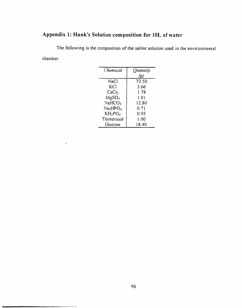
Appendix 1: Hank's Solution composition for 10L of water
The followinj is the composition of the saline solution used in the environmental
chamber.
ïhen~icnl
NaCl KCI
CaClz MgS04 SaHC03 NazHPOJ W2PO.,
Thimerosol Glucose
Qimn N i y ($9
72.50 3 -66 1.78 1 .O 1
12.SO 0.7 1 0.95 1 .O0
15.40
IMAGE EVALUATION TEST TARGET (QA-3)
APPLIED fi. IMAGE. lnc - = 1653 East Main Street - -. - Rochester. NY 14609 USA -- -- - - Phone: 71 6/482-OXKl -- -- Fax: 71 61288-5989
8 1993. App(ied Image, Inc.. All Rights R e s e W