Compression Testing of Single Column Studs with … august single columns...Compression Testing of...
94
Compression Testing of Single Column Studs with Sheathing Configurations Yared Shifferaw, Luiz Vieira and Ben Schafer Department of Civil Engineering Johns Hopkins University August 2009
-
Upload
vuongnguyet -
Category
Documents
-
view
216 -
download
0
Transcript of Compression Testing of Single Column Studs with … august single columns...Compression Testing of...

Compression Testing of Single Column Studs with Sheathing Configurations
Yared Shifferaw, Luiz Vieira and Ben Schafer
Department of Civil Engineering
Johns Hopkins University
August 2009

Introduction The stability of C-section columns with different sheathing configurations subjected to compression is the subject of this report. Column configurations with and without sheathing were tested for compressive capacity. Two types of sheathing were considered: oriented strand board (OSB) and gypsum board (GYP). The influence of OSB and GYP sheathing on the compressive carrying capacity of the columns was investigated. A total of 26 tests on short, intermediate and long columns were carried out. To examine the role of boundary conditions the top and bottom ends of the column studs were either left free or connected to tracks through screws with OSB and/or GYP sheathing attached to one or both sides of the studs and tracks. Imperfections of the columns were measured at six cross-section locations. These locations and direction of the imperfection measurements were chosen such that the possible deformed configurations of local, distortional and global buckling can be captured. For each of the columns, measurements at 75 local, 25 distortional and 8 global imperfection points corresponding to each cross-section location was carried out. To measure the deformations for analyzing the buckling failure types of these tests five position transducers were set up at the mid point of the studs for the 2, 4, 6 and 8 ft studs, in addition to two string pots used to measure local deformation at the ends for the 8 ft studs. The tests were conducted using a universal two-post 100 kip MTS and a custom built multi-degree-of-freedom (MDOF) testing rig capable of 200 kips compression and being utilized for testing of full walls in a companion research project which gave load-displacement and position transducer records to aid in understanding of the effects of different combinations of sheathings and boundary conditions on the stability of columns, and the impact of composite action of the sheathings when acting as direct load-bearing component. Acknowledgments Acknowledgments are extended to AISI, Nickolay Logvinovsky and undergraduate researchers (Mo Alkyasi, Lauren Thompson, Linda Wan and Maggie Wildnauer) and to Simpson Strong-Tie for providing materials used in the tests.

Cross-section Dimension Measurements Cross-section dimension measurements of the 362S162-68 (SSMA/ASTM nomenclature) studs and 362T125-68 tracks are given in Appendix D. The dimensions of these measurements are given in Figure 1 with the following notations: H out-to-out height of web BA out-to-out flange width of side A BB out-to-out flange width of side B DA out-to-out lip height of side A DB out-to-out lip height of side B rhbA outer radius of corner near the web on side A rhbB outer radius of corner near the web on side B rdbA outer radius of corner near the lip on side A rdbB outer radius of corner near the lip on side B θhbA outer angle of corner near the web on side A θhbB outer angle of corner near the web on side B θdbA outer angle of corner near the lip on side A θdbB outer angle of corner near the lip on side B t* web / flange thickness, including galvanizing
Figure 1 Cross-section dimension notations
Coupon Test
Columns and tracks where chosen randomly from the single column specimens already tested, since they used the same material. Steel plates where roughly cut from the web and outside the yielded area, the dimension entered in the CNC milling machine to precisely cut the coupon specimen is showed in Figure 2.
H
BB
DB
DA
rhbB
rdbA rhbA
BA
rdbB
θhbB θdbB
θdbAθhbA
t

0.79 in.
1.97 in.
1.97 in.
3.18 in. 1.97 in.
0.38 in.0.38 in.
R=0.55 in.
0.492 in. *
gauge length
*nominal, actual dimension will vary slightly Figure 2 – Tensile coupon dimensions (Moen (2008)).
The specimens after cut were immersed in hydrochloric acid, concentration of 15% in volume (85% distillated water and 15% hydrochloride acid) for 10 minutes. The hydrochloride bath is necessary to remove the zinc coating and then be able to measure the specimen dimensions without the coating. Figure 3 shows the test set up and one of the specimens after tested. Two methods were used to find the yielding stress, the 0.2% offset method and the autograph method. Basically the 0.2% method consider the yielding stress equal to the stress where the stiffness line (Young’s modulus = E = 29500ksi) is offset from the origin to the 0.2% engineering strain and it intersect the stress-strain curve, on the other hand, the autograph method use the same offset technique but the lines are offset to 0.4% and 0.8% of the strain and the yielding stress is the average value in the range between the two lines. All the data is discretized and given in Appendix G. The authors consider the 0.2% offset method the most appropriate method to find the yielding stress for the steel used in the studs because there is no yielding plateau as shown in Appendix H. On the other hand, the steel used in the track has the yielding plateau and then the autograph method is more appropriate; if the 0.2% method is used to define the yielding stress the value will be a peak value as shown in Appendix I.
a) Test set-up b) Coupon failed Figure 3 – Tensile coupon test.

Imperfection Measurements Imperfections were measured via a rig synchronized with LVDT for automatic recording in labview. Local imperfection measurements (point D on Figure 4) were made at 0.5 in. spacing along a foot span at the center and either ends. Distortional imperfection measurements (points A and F) were made at 1 in. spacing along a 2 ft span at the center whereas global imperfections (points B, C and E) were recorded every foot along the length of the member. Figure 5 shows a labview window of imperfection recording for an 8 ft member. Figure 6 shows plots of web and flange imperfections along with bow, camber and twist plots of the members computed based on the global imperfection measurements for an 8 ft member. Imperfection plots of the members tested are given in Appendix E.
Figure 4 Cross-section imperfection measurement locations
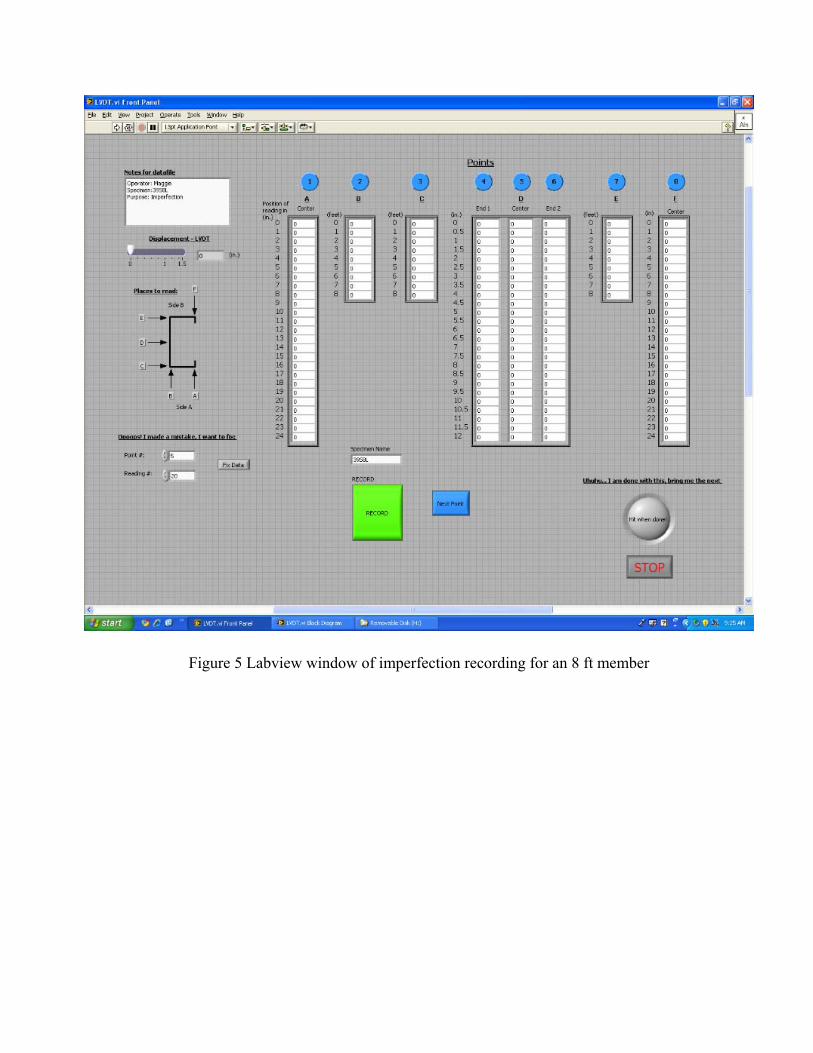
Figure 5 Labview window of imperfection recording for an 8 ft member

0 0.1 0.2 0.3 0.4 0.5 0.6 0.7 0.8 0.9 1-0.05
0
0.05
flang
e a
imp.
(in.
)
65S8L-IMPdata-03-23-2009-07-21-02.txt
0 0.1 0.2 0.3 0.4 0.5 0.6 0.7 0.8 0.9 1-0.05
0
0.05
web
imp.
(in.
)
0 0.1 0.2 0.3 0.4 0.5 0.6 0.7 0.8 0.9 1-0.05
0
0.05
x/L (L=96in. or 2438.4mm)
flang
e b
imp.
(in.
)
AB
CDE
F
0 2 4 6 8 10 12-0.05
0
0.05
x (in.)
web
imp.
(in.
)
end1centerend 2
0 5 10 15 20-0.05
0
0.05
x (in.)
flang
e/lip
imp.
(in.
)
65S8L-IMPdata-03-23-2009-07-21-02.txt
side a, centerside b, center
0 10 20 30 40 50 60 70 80 90-0.05
0
0.05
x (in.)
imp.
(in.
or r
ad)
bowcambertwist
Figure 6 Imperfection plots for an 8 ft member

Sheathing Types OSB (7/16 in., rated 24/16, exposure 1) and gypsum (½ in. Sheetrock) are the two types of sheathing used. The notations used to represent the sheathing configurations in the tests are given in Table 1. All tests with sheathing include stud and tracks. The humidity level during testing was on average 62%.
Table 1 Sheathing Configurations Sheathing Configuration Description OSB - BARE OSB on one side of stud OSB - GYP OSB on one side, gypsum on the other side of studGYP - GYP Gypsum on both sides of stud OSB - OSB OSB on both sides of stud
Test Configurations A typical specimen notation used in the tests is given by: 1- BARE – BARE – 7S6L-6-T-S-P This corresponds to: # of test – Side 1 – Side 2 – Test name – Length – Track – Sheathing – Plate Examples of the test configurations considered are shown in Figure 7 with the full list given in Appendix A.
a) 18-OSB–BARE–4S2LTSP-2-T-S-P
b) 15-GYP–GYP–4S4LTSP-4-T-S-P
c) 3- BARE–BARE–1S4L-4
Figure 7 Examples of test configurations

Test Apparatus and Loading Details The tests were done using MTS and multi-axial testing rig MDOF machines. Compressive load was applied through the bottom load cell for the case of the MTS. The vertical displacement in the tests that use the MTS machine was measured through a position transducer in-built at the bottom load cell as shown in Figure 8. A small isolation plate was provided between the loading plate and the track for some of the tests with the MTS machine as shown in Figure 9. For the MDOF machine, compressive loading was applied through four actuators at the top and the vertical displacement was measured as the average of the vertical displacements measured through in-built position transducers in these actuators. Direction of vertical displacement, loading, and position of actuators for the MDOF machine is shown in Figure 10.
Figure 8 MTS and vertical displacement measurement location
Figure 9 Isolation plate between loading plate and track used in the MTS machine

Figure 10 MDOF and vertical displacement measurement locations
Sheathing-Stud-Track Connection Details Number 6 screws (Simpson #6 x 1 5/8’’) were used to connect to the gypsum boards and number 8 screws (Simpson #8 x 1 15/16’’) were used to connect to the OSB boards as shown in Figure 11.
a) Stud-Track connection b) Sheathing-Stud-Track connection
Figure 11 Connection details

Position Transducers Five position transducers and two string pots were set up at the midpoint and ends of the members respectively as shown in Figure 12 to capture local and global buckling for the different test configurations.
Figure 12 a Position transducers and string pots
Figure 12 b Notation for position transducers
Discussion of Results Discussion of representative results among the tests will be presented based on configurations of sheathing, length of member, and type of boundary conditions adopted throughout the tests as follows. BARE-BARE WITHOUT TRACK 4-BARE-BARE-1S2L-2 This test was carried out for a 2ft long column with ends directly bearing against the load platens of the MTS machine. At the top end (end 1), there was a noticeable gap between the load platen and stud end as shown in Figure 13 a. As can be observed the contact with the load platen was on the lips side with
a) Test set-up of a 4ft stud
b) Position transducers on a 4’ stud
c) String pots on an 8’ stud
PT1
PT3 PT4 PT5
PT2

the web and flange having barely any contact. The loading rate on the MTS machine was 0.0132 in/sec. After loading for 12 kips the gap was still present though closing in and it was observed that the lips open out at the top end. Global deformation could also be observed from the beginning as the load bearing on the lips directly lead to eccentric loading as can be seen from the movement of web position transducers 3, 4 and 5. At 16 kips the gap closes with distortional buckling starting to form at the top end and continuing through the length of the member. Distortional buckling at the mid length of the member was captured by position transducers 1 and 2 as shown in Figure 13 b. As the top end’s gap closed failure was seen to be concentrated at the bottom end where there was a large imperfection. This resulted in the bottom end’s (end 2) local failure close to 21 kips. At the peak load (21.74 kips, Figure 13 c) visible distortional and web plate (local) failures were observed at the bottom end as shown in Figure 13 d.
Figure 13 a) Gap between load platen and stud end for test 4-BARE-BARE-1S2L-2
0 0.05 0.1 0.15 0.2 0.25 0.3 0.35 0.4-0.1
0
0.1
0.2
0.3
0.4
0.5
0.6
position (in)
disp
lace
men
t (in
)
4-BARE-BARE-1S2L-2,2.txt
Position Transducer 1Position Transducer 2Position Transducer 3Position Transducer 4Position Transducer 5
Figure 13 b) Position transducers’ graph for test 4-BARE-BARE-1S2L-2

0 0.05 0.1 0.15 0.2 0.25 0.3 0.35
5
10
15
20
4-BARE-BARE-1S2L-2.dat
max P = 21.74 kip
position (in)
load
(kip
)
Figure 13 c) Load-displacement graph for test 4-BARE-BARE-1S2L-2
Figure 13 d) Deformation at failure for test 4-BARE-BARE-1S2L-2 BARE-BARE WITH TRACK 5-BARE-BARE-1S2LT-2-T In this test, the 2 ft stud was connected with tracks on the top and bottom. Gaps between track and load platen and between track and stud were observed at both ends with the top end showing a larger gap

(approximately 1/16”) as shown in Figure 14 a. Distortional buckling was observed as load reached 21 kips with the channel lips distorting inward as indicated by position transducers 1 and 2 in Figure 14 b and those at the ends distorting outward. Local buckling wave at the ends was observed at 23 kips closer to the peak load. The bottom end of stud was found to have more local deformation than the top since load is applied through the bottom (or higher imperfection at this end). After peak load, weak axis global buckling was observed. The load-displacement graph given in Figure 14 c indicates more ductile response provided by the addition of tracks in this test in comparison to that shown in Figure 14c for the stud test with no tracks.
Figure 14 a) Gap between load platen and stud end for test 5-BARE-BARE-1S2LT-2-T
-0.05 0 0.05 0.1 0.15 0.2 0.25 0.3 0.35 0.4 0.45-0.5
0
0.5
1
1.5
2
position (in)
disp
lace
men
t (in
)
5-BARE-BARE-1S2LT-2-T.dat
Position Transducer 1Position Transducer 2Position Transducer 3Position Transducer 4Position Transducer 5
Figure 14 b) Position transducers’ graph for test 5-BARE-BARE-1S2LT-2-T

0 0.05 0.1 0.15 0.2 0.25 0.3 0.35 0.4
5
10
15
20
25
5-BARE-BARE-1S2LT-2-T.dat
max P = 23.07 kip
position (in)
load
(kip
)
Figure 14 c) Load-displacement graph for test 5-BARE-BARE-1S2LT-2-T
Figure 14 d) Deformation at failure for test 5-BARE-BARE-1S2LT-2-T
22-BARE-BARE-61S8LTP-8-T-P In this test, an 8 ft stud with tracks was axially-loaded using the MDOF machine. Weak axis flexure was observed as the load reached 12 kips (Figure 15 c). This can be seen from the three web position transducers (3, 4 and 5) as shown in Figure 15 a. The peak load was found to be 12.84 kips from the load-displacement graph in Figure 15 b. Flexural-torsional buckling was also observed along with local web plate buckling due to bending in the post-peak range as shown in Figure 15 c.

0 0.05 0.1 0.15 0.2 0.25 0.3 0.35 0.4-1.2
-1
-0.8
-0.6
-0.4
-0.2
0
0.2
position (in)
disp
lace
men
t (in
)
22-BARE-BARE-61S8LTP-8-T-P,2.txt
Position Transducer 1Position Transducer 2Position Transducer 3Position Transducer 4Position Transducer 5String Pot 3String Pot 4
Figure 15 a) Position transducers’ graph for test 22-BARE-BARE-61S8LTP-8-T-P
0 0.05 0.1 0.15 0.2 0.25 0.3 0.35 0.4 0.45
2
4
6
8
10
12
14
22-BARE-BARE-61S8LTP-8-T-P.dat
max P = 12.84 kip
position (in)
load
(kip
)
Figure 15 b) Load-displacement graph for test 22-BARE-BARE-61S8LTP-8-T-P

i) Weak axis flexural buckling
ii) web plate buckling
Figure 15 c) Deformations for test 22-BARE-BARE-61S8LTP-8-T-P
OSB-BARE WITH TRACK AND PLATE 23-OSB-BARE-62S8LTSP-8-T-S-P The sheathing configuration in this test is such that OSB is provided on only one side of the 8 ft column. Tracks are attached to the top and bottom of the stud, with small loading plates transferring load directly to the tracks i.e. no direct loading of the sheathing is allowed. The failure type observed is strong axis flexural-torsional buckling as can be seen from the movements of position transducers 4 and 5 on Figure 16 a and deformation on Figure 16 c. A peak load of 15.64 kips was observed as shown in the load-displacement plot given on Figure 16 b.
-0.05 0 0.05 0.1 0.15 0.2 0.25 0.3 0.35-0.2
-0.15
-0.1
-0.05
0
0.05
0.1
0.15
0.2
0.25
position (in)
disp
lace
men
t (in
)
23-OSB-BARE-62S8LTSP-8-T-S-P,2.txt
Position Transducer 1Position Transducer 2Position Transducer 3Position Transducer 4Position Transducer 5String Pot 3String Pot 4
Figure 16 a) Position transducers’ graph for test 23-OSB-BARE-62S8LTSP-8-T-S-P

0 0.05 0.1 0.15 0.2 0.25 0.3 0.35 0.4
2
4
6
8
10
12
14
16
23-OSB-BARE-62S8LTSP-8-T-S-P.dat
max P = 15.64 kip
position (in)
load
(kip
)
Figure 16 b) Load-displacement graph for test 23-OSB-BARE-62S8LTSP-8-T-S-P
Figure 16 c) Deformation at failure for test 23-OSB-BARE-62S8LTSP-8-T-S-P
GYP- GYP NON-DIRECT LOAD BEARING (WITH PLATE) 19-GYP-GYP-3S2LTSP-2-T-S-P Gypsum sheathing on both sides of the stud is provided for this 2 ft test under axial loading in the MTS machine. In this test, the gypsum sheathing is not in direct contact with the load platen as there is provision of a small plate to transfer load to the tracks directly. With loading close to 22.5 kips

distortional buckling was observed at the ends followed by crushing of the web at the ends at 25kips (Figure 17 c). Peak load for this specimen was found to be 25.37 kips (Figure 17 b) followed by screws popping out from the side of gypsum as can be observed in Figure 17 c.
-0.2 -0.1 0 0.1 0.2 0.3 0.4 0.5-0.1
0
0.1
0.2
0.3
0.4
0.5
0.6
0.7
0.8
position (in)
disp
lace
men
t (in
)
19-GYP-GYP-3S2LTSP-2-T-S-P.dat
Position Transducer 1Position Transducer 2Position Transducer 3Position Transducer 4Position Transducer 5
Figure 17 a) Position transducers’ graph for test 19-GYP-GYP-3S2LTSP-2-T-S-P

0 0.05 0.1 0.15 0.2 0.25 0.3 0.35
5
10
15
20
25
19-GYP-GYP-3S2LTSP-2-T-S-P.dat
max P = 25.37 kip
position (in)
load
(kip
)
Figure 17 b) Load-displacement graph for test 19-GYP-GYP-3S2LTSP-2-T-S-P
Figure 17 c) Deformation at failure for test 19-GYP-GYP-3S2LTSP-2-T-S-P

GYP- GYP DIRECT LOAD BEARING (WITHOUT PLATE) 11-GYP-GYP-8S6LTS-6-T-S A 6 ft stud was tested with gypsum-gypsum sheathing on both sides. In this test the track and gypsum bear on the load platen with no small additional plate to transfer load to track. The top end (end 2) showed initiation of web local buckling with the gypsum sheathing crushing at this end (Figure 18 c). As can be observed from Figure 18 a, position transducers 1 and 2 pick up the deformation at mid length of the member. Peak load reaches 27.66 kips as shown in Figure 18 b.
-0.1 0 0.1 0.2 0.3 0.4 0.5 0.6 0.7-0.2
-0.15
-0.1
-0.05
0
0.05
0.1
0.15
position (in)
disp
lace
men
t (in
)
11-GYP-GYP-8S6LTS-6-T-S.dat
Position Transducer 1Position Transducer 2Position Transducer 3Position Transducer 4Position Transducer 5
Figure 18 a) Position transducers’ graph for test 11-GYP-GYP-8S6LTS-6-T-S

0 0.1 0.2 0.3 0.4 0.5
5
10
15
20
25
30
11-GYP-GYP-8S6LTS-6-T-S.dat
max P = 27.66 kip
position (in)
load
(kip
)
Figure 18 b) Load-displacement graph for test 11-GYP-GYP-8S6LTS-6-T-S
Figure 18 c) Deformation at failure for test 11-GYP-GYP-8S6LTS-6-T-S OSB-GYP WITH PLATE 20-OSB-GYP-5S2LTSP-2-T-S-P The sheathing configuration for this test is combined OSB and GYP on a 2 ft stud. Plates are used to transfer load to the tracks. At 22.5 kips local waves were observed at the ends. At peak (Figure 19 b), distortional buckling along with local web crushing at the top end was observed (Figure 19 c). Sudden
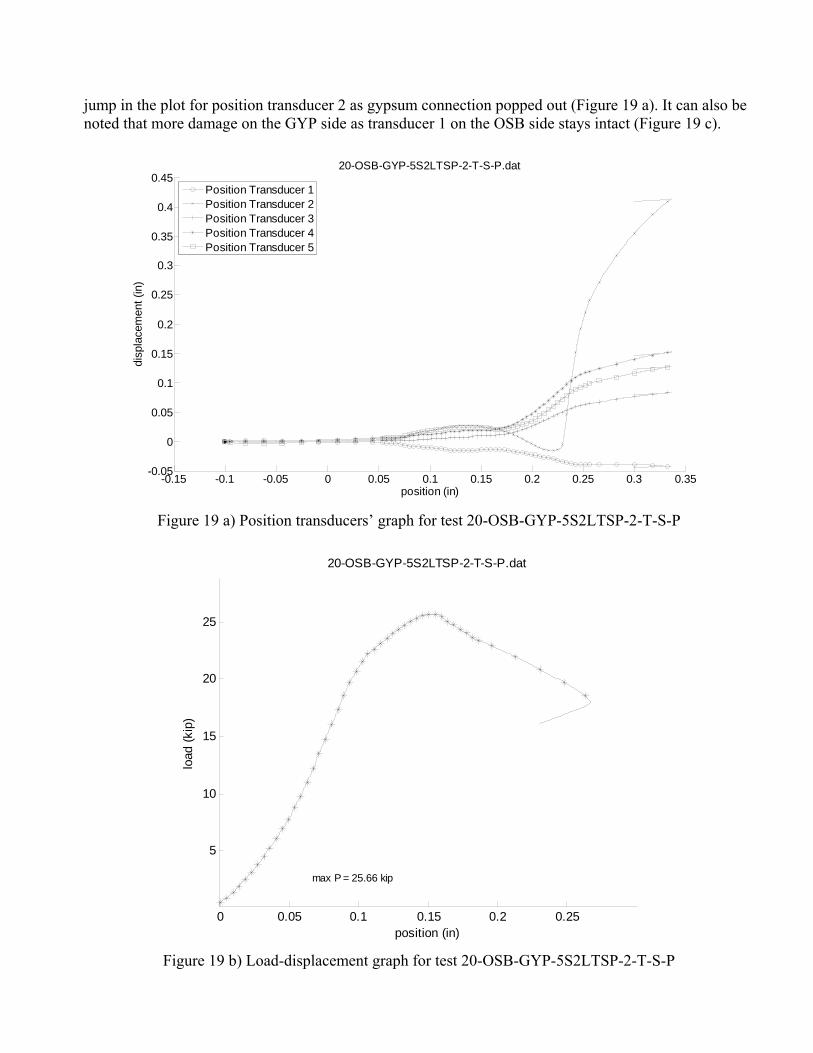
jump in the plot for position transducer 2 as gypsum connection popped out (Figure 19 a). It can also be noted that more damage on the GYP side as transducer 1 on the OSB side stays intact (Figure 19 c).
-0.15 -0.1 -0.05 0 0.05 0.1 0.15 0.2 0.25 0.3 0.35-0.05
0
0.05
0.1
0.15
0.2
0.25
0.3
0.35
0.4
0.45
position (in)
disp
lace
men
t (in
)
20-OSB-GYP-5S2LTSP-2-T-S-P.dat
Position Transducer 1Position Transducer 2Position Transducer 3Position Transducer 4Position Transducer 5
Figure 19 a) Position transducers’ graph for test 20-OSB-GYP-5S2LTSP-2-T-S-P
0 0.05 0.1 0.15 0.2 0.25
5
10
15
20
25
20-OSB-GYP-5S2LTSP-2-T-S-P.dat
max P = 25.66 kip
position (in)
load
(kip
)
Figure 19 b) Load-displacement graph for test 20-OSB-GYP-5S2LTSP-2-T-S-P

Figure 19 c) Deformation at failure for test 20-OSB-GYP-5S2LTSP-2-T-S-P 24-OSB-GYP-63S8LTSP-8-T-S-P The MDOF machine was used for this 8 ft OSB-GYP sheathing configuration tested with plates used to isolate load to the tracks. String pots 3 and 4 at the ends were observed to pick up the local deformation as shown in Figure 20 a. Distortional buckling at the top end as shown in Figure 20 c leads to more damage on the GYP side and leads to screws popping out on this side. The load-displacement plot is shown in Figure 20 b with the peak load at 22.45 kips.
0.05 0.1 0.15 0.2 0.25 0.3 0.35 0.4 0.45 0.5 0.55-0.2
-0.15
-0.1
-0.05
0
0.05
0.1
0.15
position (in)
disp
lace
men
t (in
)
24-OSB-GYP-63S8LTSP-8-T-S-P,2.txt
Position Transducer 1Position Transducer 2Position Transducer 3Position Transducer 4Position Transducer 5String Pot 3String Pot 4
Figure 20 a) Position transducers’ graph for test 24-OSB-GYP-63S8LTSP-8-T-S-P

0 0.1 0.2 0.3 0.4 0.5 0.6
5
10
15
20
2524-OSB-GYP-63S8LTSP-8-T-S-P.dat
max P = 22.45 kip
position (in)
load
(kip
)
Figure 20 b) Load-displacement graph for test 24-OSB-GYP-63S8LTSP-8-T-S-P
Figure 20 c) Deformation at failure for test 24-OSB-GYP-63S8LTSP-8-T-S-P

OSB-OSB WITH PLATE 26-OSB-OSB-65S8LTSP-S-T-S-P OSB sheathing on both sides of an 8 ft stud with tracks loaded through plates was considered for this test. As the load reaches 21 kips, the string pot on the top was observed to pick up the movement as shown in Figure 21 a. As the peak load approached (Figure 21 b), the bottom string pot was observed to pick up the corresponding local buckling at that end. The sign of distortional buckling at the top can be seen from Figure 21 c as screws started tilting.
0 0.1 0.2 0.3 0.4 0.5 0.6 0.7-0.2
-0.1
0
0.1
0.2
0.3
0.4
0.5
0.6
position (in)
disp
lace
men
t (in
)
26-OSB-OSB-65S8LTSP-8-T-S-P,2.txt
Position Transducer 1Position Transducer 2Position Transducer 3Position Transducer 4Position Transducer 5String Pot 3String Pot 5
Figure 21 a) Position transducers’ graph for test 26-OSB-OSB-65S8LTSP-8-T-S-P
0 0.1 0.2 0.3 0.4 0.5 0.6
5
10
15
20
25
26-OSB-OSB-65S8LTSP-8-T-S-P.dat
max P = 23.09 kip
position (in)
load
(kip
)
Figure 21 b) Load-displacement graph for test 26-OSB-OSB-65S8LTSP-8-T-S-P

Figure 21 c) Deformation at failure for test 26-OSB-OSB-65S8LTSP-8-T-S-P

SUMMARY OF RESULTS
Deformation at failure for all the tests is given in Appendix B. Appendix C and F give load-displacement and position transducers’ plots. Summary of the peak loads and failure mechanisms for the tests are given in Table 2. For the BARE-BARE configuration, the 8 ft studs showed flexural buckling failure mechanism, the 6 ft and 4 ft studs showed combination of local and global failures depending on the presence of tracks, and the 2 ft studs failed locally either in local or distortional buckling. For the OSB-BARE configuration, the 8 ft and 6ft studs failed in flexural-torsional buckling with the rest of studs failing locally at the ends. For the configurations OSB-OSB, OSB-GYP and GYP-GYP all the studs were observed to fail locally at the ends.
Figure 22 shows comparison of the peak compressive load capacities for the 2, 4, 6 and 8 ft studs connected to tracks with different sheathing configurations and loading condition such that studs carry load via isolation plate directly above the tracks. As can be seen from Figure 22, the provision of sheathing restrictions increases the capacities of these studs with OSB – OSB sheathing configuration leading to the maximum strength results and BARE-BARE configuration resulting in the minimum strength with others lying in between. Overall the performance of OSB-GYP sheathing configuration was found to be comparable to that of the GYP-GYP configuration in these observations.
The load-displacement graphs for the different sheathing configurations of the 2, 4, 6 and 8 ft studs are given in Figures 23-26. Figures 27-30 give comparison of load-displacement graphs for the different lengths of studs considered in the test. Load-displacement results for the tests examining the effect of tracks are given in Figures 31 and 32. It was observed that the presence of tracks increased the peak loads of the 2 ft by 6%, with no significant increase for the 4 and 6 ft studs. Figures 33 and 34 show the effect of bearing track on plate for OSB-OSB and GYP-GYP sheathing restrictions.

Table 2 Peak load and failure mechanisms
Test Specimen Peak Load (Kips) Failure Mechanism 1-BARE-BARE-7S6L-6 17.38 Flexural 2-BARE-BARE-1S6L-6 15.64 Flexural 3-BARE-BARE-1S4L-4 22.58 Distortional 4-BARE-BARE-1S2L-2 21.74 Distortional 5-BARE-BARE-1S2LT-2-T 23.07 Distortional 6-BARE-BARE-2S4LT-4-T 22.2 Flexural Torsional 7-BARE-BARE-2S6LT-6-T 15.86 Flexural Torsional 8-OSB-OSB-3S6LTS-6-T-S 31.29 Local at end 9-OSB-OSB-4S6LTSP-6-T-S-P 26.11 Local at end 10-GYP-GYP-5S6LTSP-6-T-S-P 23.27 Local at end 11-GYP-GYP-8S6LTSP-6-T-S 27.66 Local at end 12-OSB-BARE-6S6LTSP-6-T-S-P 21.02 Flexural Torsional 13-OSB-GYP-7S6LTSP-6-T-S-P 23.9 Local at end 14-OSB-BARE-3S4LTSP-4-T-S-P 25.66 Local at end 15-GYP-GYP-4S4LTSP-4-T-S-P 26.13 Local at end 16-GYP-OSB-5S4LTSP-4-T-S-P 25.23 Local at end 17-OSB-OSB-6S4LTSP-4-T-S-P 25.97 Local at end 18-OSB-BARE-4S2LTSP-2-T-S-P 25.03 Local at end 19-GYP-GYP-3S2LTSP-2-T-S-P 25.37 Local at end 20-OSB-GYP-5S2LTSP-2-T-S-P 25.66 Local at end 21-OSB-OSB-6S2LTSP-2-T-S-P 26.65 Local at end 22-BARE-BARE-61S8LTP-8-T-P 12.84 Flexural 23-OSB-BARE-62S8LTSP-8-T-S-P 15.64 Flexural Torsional 24-OSB-GYP-63S8LTSP-8-T-S-P 22.45 Local at end 25-GYP-GYP-64S8LTSP-8-T-S-P 21.37 Local at end 26-OSB-OSB-65S8LTSP-8-T-S-P 23.09 Local at end

0 1 2 3 4 5 6 7 8 9 1010
12
14
16
18
20
22
24
26
28
30
length (foot)
load
(kip
)
OSB-OSBOSB-BAREBARE-BAREGYP-GYPOSB-GYP
Figure 22 Compressive load vs. column length for the different sheathing combinations
0 0.05 0.1 0.15 0.2 0.25 0.3 0.35 0.40
5
10
15
20
25
position (in)
load
(kip
)
2 feet stud with different combination of restrictions
4-BARE-BARE-1S2L-2.dat5-BARE-BARE-1S2LT-2-T.dat18-OSB-BARE-4S2LTSP-2-T-S-P.dat19-GYP-GYP-3S2LTSP-2-T-S-P.dat20-OSB-GYP-5S2LTSP-2-T-S-P.dat21-OSB-OSB-6S2LTSP-2-T-S-P.dat
Figure 23 Load-displacement curves for 2ft stud with different combination of sheathing restrictions

0 0.05 0.1 0.15 0.2 0.25 0.3 0.35 0.4 0.450
5
10
15
20
25
position (in)
load
(kip
)
4 feet stud with different combination of restrictions
3-BARE-BARE-1S4L-4.dat6-BARE-BARE-2S4LT-4-T.dat14-OSB-BARE-3S4LTSP-4-T-S-P.dat15-GYP-GYP-4S4LTSP-4-T-S-P.dat16-GYP-OSB-5S4LTSP-4-T-S-P.dat17-OSB-OSB-6S4LTSP-4-T-S-P.dat
Figure 24 Load-displacement curves for 4ft stud with different combination of sheathing restrictions
0 0.1 0.2 0.3 0.4 0.5 0.6
5
10
15
20
25
position (in)
load
(kip
)
6 feet stud with different combination of restrictions
2-BARE-BARE-1S6L-6.dat7-BARE-BARE-2S6LT-6-T.dat9-OSB-OSB-4S6LTSP-6-T-S-P.dat10-GYP-GYP-5S6LTSP-6-T-S-P.dat12-OSB-BARE-6S6LTSP-6-T-S-P.dat13-OSB-GYP-7S6LTSP-6-T-S-P.dat
Figure 25 Load-displacement curves for 6ft stud with different combination of sheathing restrictions

0 0.1 0.2 0.3 0.4 0.5 0.60
5
10
15
20
25
position (in)
load
(kip
)
8 feet stud with different combination of restrictions
22-BARE-BARE-61S8LTP-8-T-P.dat23-OSB-BARE-62S8LTSP-8-T-S-P.dat24-OSB-GYP-63S8LTSP-8-T-S-P.dat25-GYP-GYP-64S8LTSP-8-T-S-P.dat26-OSB-OSB-65S8LTSP-8-T-S-P.dat
Figure 26 Load-displacement curves for 8ft stud with different combination of sheathing restrictions
0 0.05 0.1 0.15 0.2 0.25 0.3 0.35 0.40
5
10
15
20
25
position (in)
load
(kip
)
Comparison between different lengths, case OSB-Bare
12-OSB-BARE-6S6LTSP-6-T-S-P.dat14-OSB-BARE-3S4LTSP-4-T-S-P.dat18-OSB-BARE-4S2LTSP-2-T-S-P.dat23-OSB-BARE-62S8LTSP-8-T-S-P.dat
Figure 27 Load-displacement curves for 2, 4, 6 and 8 ft studs with OSB-BARE sheathing restriction

0 0.1 0.2 0.3 0.4 0.5 0.60
5
10
15
20
25
position (in)
load
(kip
)
Comparison between different lengths, case OSB-OSB
9-OSB-OSB-4S6LTSP-6-T-S-P.dat17-OSB-OSB-6S4LTSP-4-T-S-P.dat21-OSB-OSB-6S2LTSP-2-T-S-P.dat26-OSB-OSB-65S8LTSP-8-T-S-P.dat
Figure 28 Load-displacement curves for 2, 4, 6 and 8 ft studs with OSB-OSB sheathing restriction
0 0.1 0.2 0.3 0.4 0.5 0.60
5
10
15
20
25
position (in)
load
(kip
)
Comparison between different lengths, case OSB-GYP
13-OSB-GYP-7S6LTSP-6-T-S-P.dat16-GYP-OSB-5S4LTSP-4-T-S-P.dat20-OSB-GYP-5S2LTSP-2-T-S-P.dat24-OSB-GYP-63S8LTSP-8-T-S-P.dat
Figure 29 Load-displacement curves for 2, 4, 6 and 8 ft studs with OSB-GYP sheathing restriction
0 0.1 0.2 0.3 0.4 0.50
5
10
15
20
25
position (in)
load
(kip
)
Comparison between different lengths, case GYP-GYP
10-GYP-GYP-5S6LTSP-6-T-S-P.dat15-GYP-GYP-4S4LTSP-4-T-S-P.dat19-GYP-GYP-3S2LTSP-2-T-S-P.dat25-GYP-GYP-64S8LTSP-8-T-S-P.dat
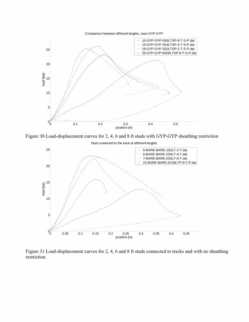
Figure 30 Load-displacement curves for 2, 4, 6 and 8 ft studs with GYP-GYP sheathing restriction
0 0.05 0.1 0.15 0.2 0.25 0.3 0.35 0.4 0.450
5
10
15
20
25
position (in)
load
(kip
)
Stud connected to the track at different lengths
5-BARE-BARE-1S2LT-2-T.dat6-BARE-BARE-2S4LT-4-T.dat7-BARE-BARE-2S6LT-6-T.dat22-BARE-BARE-61S8LTP-8-T-P.dat
Figure 31 Load-displacement curves for 2, 4, 6 and 8 ft studs connected to tracks and with no sheathing restriction
0 0.1 0.2 0.3 0.4 0.5 0.6
5
10
15
20
25
position (in)
load
(kip
)
Stud at different lengths
2-BARE-BARE-1S6L-6.dat3-BARE-BARE-1S4L-4.dat4-BARE-BARE-1S2L-2.dat
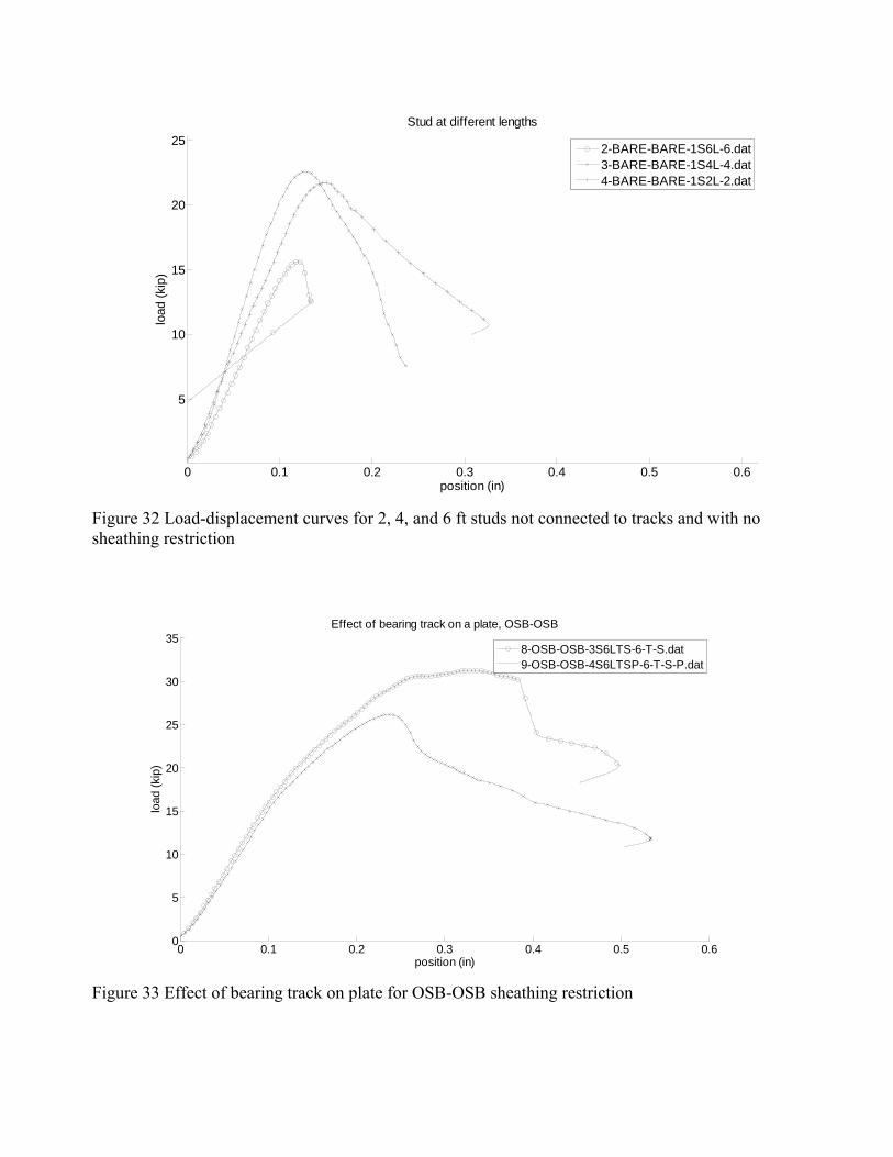
Figure 32 Load-displacement curves for 2, 4, and 6 ft studs not connected to tracks and with no sheathing restriction
0 0.1 0.2 0.3 0.4 0.5 0.60
5
10
15
20
25
30
35
position (in)
load
(kip
)
Effect of bearing track on a plate, OSB-OSB
8-OSB-OSB-3S6LTS-6-T-S.dat9-OSB-OSB-4S6LTSP-6-T-S-P.dat
Figure 33 Effect of bearing track on plate for OSB-OSB sheathing restriction

0 0.1 0.2 0.3 0.4 0.50
5
10
15
20
25
30
position (in)
load
(kip
)
Effect of bearing track on a plate, GYP-GYP
10-GYP-GYP-5S6LTSP-6-T-S-P.dat11-GYP-GYP-8S6LTS-6-T-S.dat
Figure 34 Effect of bearing track on plate for GYP-GYP sheathing restriction

APPENDIX
A) Test Set-ups and Sheathing Configurations
BARE-BARE
a) 2-ft
b) 4-ft
c) 6-ft
d) 8-ft

OSB-BARE
a) 2-ft
b) 4-ft
c) 6-ft d) 8-ft

GYP-GYP
a) 2-ft
b) 4-ft
c) 6-ft d) 8-ft

OSB-GYP
a) 2-ft
b) 4-ft
c) 6-ft d) 8-ft

OSB-OSB
a) 2-ft
b) 4-ft
c) 6-ft d) 8-ft

B) Tests at failure
BARE-BARE
a) 2-ft
b) 4-ft
c) 6-ft d) 8-ft

OSB-BARE
a) 2-ft
b) 4-ft
c) 6-ft
d) 8-ft

GYP-GYP
a) 2-ft
b) 4-ft
c) 6-ft
d) 8-ft

OSB-GYP
a) 2-ft
b) 4-ft
c) 6-ft
d) 8-ft

OSB-OSB
a) 2-ft
b) 4-ft
c) 6-ft
d) 8-ft

C) Load – Displacement Graphs for the Tests
0 0.05 0.1 0.15 0.2
5
10
15
1-BARE-BARE-7S6L-6.dat
max P = 17.38 kip
position (in)
load
(kip
)
0 0.2 0.4 0.6
5
10
15
2-BARE-BARE-1S6L-6.dat
max P = 15.64 kip
position (in)
load
(kip
)
0 0.05 0.1 0.15 0.2 0.25
5
10
15
20
253-BARE-BARE-1S4L-4.dat
max P = 22.58 kip
position (in)
load
(kip
)
0 0.1 0.2 0.3
5
10
15
20
4-BARE-BARE-1S2L-2.dat
max P = 21.74 kip
position (in)
load
(kip
)
0 0.1 0.2 0.3 0.40
5
10
15
20
255-BARE-BARE-1S2LT-2-T.dat
max P = 23.07 kip
position (in)
load
(kip
)
0 0.05 0.1 0.15 0.2 0.250
5
10
15
20
6-BARE-BARE-2S4LT-4-T.dat
max P = 22.20 kip
position (in)
load
(kip
)
0 0.05 0.1 0.15 0.20
5
10
15
7-BARE-BARE-2S6LT-6-T.dat
max P = 15.86 kip
position (in)
load
(kip
)
0 0.1 0.2 0.3 0.4 0.50
10
20
30
8-OSB-OSB-3S6LTS-6-T-S.dat
max P = 31.29 kip
position (in)
load
(kip
)

0 0.2 0.4 0.60
5
10
15
20
25
9-OSB-OSB-4S6LTSP-6-T-S-P.dat
max P = 26.11 kip
position (in)
load
(kip
)
0 0.1 0.2 0.3 0.4 0.50
5
10
15
20
25
10-GYP-GYP-5S6LTSP-6-T-S-P.dat
max P = 23.27 kip
position (in)
load
(kip
)
0 0.1 0.2 0.3 0.4 0.50
10
20
3011-GYP-GYP-8S6LTS-6-T-S.dat
max P = 27.66 kip
position (in)
load
(kip
)
0 0.1 0.2 0.3 0.40
5
10
15
20
12-OSB-BARE-6S6LTSP-6-T-S-P.dat
max P = 21.02 kip
position (in)
load
(kip
)
0 0.1 0.2 0.3 0.40
5
10
15
20
25
13-OSB-GYP-7S6LTSP-6-T-S-P.dat
max P = 23.80 kip
position (in)
load
(kip
)
0 0.05 0.1 0.15 0.2 0.250
5
10
15
20
25
14-OSB-BARE-3S4LTSP-4-T-S-P.dat
max P = 24.66 kip
position (in)
load
(kip
)
0 0.1 0.2 0.3 0.40
5
10
15
20
25
15-GYP-GYP-4S4LTSP-4-T-S-P.dat
max P = 26.13 kip
position (in)
load
(kip
)
0 0.1 0.2 0.30
5
10
15
20
25
16-GYP-OSB-5S4LTSP-4-T-S-P.dat
max P = 25.23 kip
position (in)
load
(kip
)

0 0.1 0.2 0.3 0.40
5
10
15
20
25
17-OSB-OSB-6S4LTSP-4-T-S-P.dat
max P = 25.97 kip
position (in)
load
(kip
)
0 0.1 0.2 0.30
5
10
15
20
25
18-OSB-BARE-4S2LTSP-2-T-S-P.dat
max P = 25.03 kip
position (in)
load
(kip
)
0 0.1 0.2 0.30
5
10
15
20
25
19-GYP-GYP-3S2LTSP-2-T-S-P.dat
max P = 25.37 kip
position (in)
load
(kip
)
0 0.05 0.1 0.15 0.2 0.250
5
10
15
20
25
20-OSB-GYP-5S2LTSP-2-T-S-P.dat
max P = 25.66 kip
position (in)
load
(kip
)
0 0.1 0.2 0.30
5
10
15
20
25
21-OSB-OSB-6S2LTSP-2-T-S-P.dat
max P = 26.65 kip
position (in)
load
(kip
)
0 0.1 0.2 0.3 0.40
5
10
22-BARE-BARE-61S8LTP-8-T-P.dat
max P = 12.84 kip
position (in)
load
(kip
)
0 0.1 0.2 0.3 0.40
5
10
15
23-OSB-BARE-62S8LTSP-8-T-S-P.dat
max P = 15.64 kip
position (in)
load
(kip
)
0 0.2 0.4 0.60
5
10
15
20
2524-OSB-GYP-63S8LTSP-8-T-S-P.dat
max P = 22.45 kip
position (in)
load
(kip
)

0 0.1 0.2 0.3 0.4 0.50
5
10
15
20
25-GYP-GYP-64S8LTSP-8-T-S-P.dat
max P = 21.37 kip
position (in)
load
(kip
)
0 0.2 0.4 0.60
5
10
15
20
2526-OSB-OSB-65S8LTSP-8-T-S-P.dat
max P = 23.09 kip
position (in)
load
(kip
)

D) Cross-section Measurements
i) Studs
Sec. No.
H (in.)
BB (in.)
BA (in.)
DB (in.)
DA (in.)
t (in.)
rhbB (in.)
rdbB (in.)
rhbA (in.)
rdbA (in.)
θhbB (o)
θdbB (o)
θhbA (o)
θdbA (o)
ct* (mm)
3.888 1.615 1.629 0.5135 0.496 0.0724 11\64 11\64 11\64 11\64 88.3 87.3 87.4 88.6 0.3
3.6585 1.597 1.6295 0.5215 0.4945 0.0753 11\64 11\64 11\64 11\64 89.7 88.1 89.7 89.2 0.3
1S2L
3.6825 1.645 1.6405 0.517 0.501 0.0724 11\64 11\64 11\64 11\64 89.5 87.6 89.5 89.5 0.3
3.6445 1.642 1.665 0.507 0.5065 0.0713 11\64 11\64 11\64 11\64 89.7 88.4 87.3 89.7 0.3
3.6705 1.6465 1.6405 0.506 0.5055 0.0757 11\64 11\64 11\64 11\64 89.8 88.2 89.8 89.4 0.4
2S2L
3.6755 1.652 1.6365 0.5065 0.5055 0.0717 11\64 11\64 11\64 11\64 88.3 88.5 89.2 89.6 0.2
3.6685 1.6585 1.6525 0.5085 0.5125 0.071 11\64 11\64 11\64 11\64 89.5 88.7 89.7 89.5 0.4 3.6855 1.672 1.651 0.5135 0.5065 0.0719 11\64 11\64 11\64 11\64 89.9 88.5 89.8 89.5 0.4
3S2L
3.7075 1.6675 1.654 0.5065 0.5035 0.0724 11\64 11\64 11\64 11\64 89.9 88.4 89.5 89 0.4 3.6795 1.65 1.6575 0.5205 0.513 0.0719 11\64 11\64 11\64 11\64 89.9 89.4 89.9 88.6 0.3 3.6735 1.694 1.6695 0.5185 0.5125 0.0725 11\64 11\64 11\64 11\64 89.5 88.8 89.9 89.5 0.2
4S2L
3.6965 1.664 1.663 0.503 0.517 0.072 11\64 11\64 11\64 11\64 88.5 89.4 89.6 89.5 0.5 3.6765 1.6655 1.6575 0.513 0.504 0.0715 11\64 11\64 11\64 11\64 89.4 88.6 88.6 89.3 0.4 3.673 1.6575 1.655 0.5075 0.5065 0.0725 11\64 11\64 11\64 11\64 89.5 89.5 89.2 89.6 0.4
5S2L
3.687 1.661 1.6515 0.5125 0.51 0.072 11\64 11\64 11\64 11\64 89.2 89.2 89 89.8 0.4 3.678 1.6685 1.6565 0.507 0.509 0.0727 11\64 11\64 11\64 11\64 89.4 89.2 89.1 89 0.5 3.6725 1.663 1.659 0.514 0.5075 0.0746 11\64 11\64 11\64 11\64 90 89.8 89.1 89.6 0.5
6S2L
3.671 1.6665 1.6535 0.5105 0.512 0.0719 11\64 11\64 11\64 11\64 89.3 89.8 89.2 89 0.3 3.679 1.638 1.654 1.1575 1.36 0.0756 11\64 11\64 11\64 11\64 88.9 89.1 87.8 89.8 0.5 3.6855 1.663 1.631 1.133 1.1145 0.078 11\64 11\64 11\64 11\64 90 89.5 86.3 89.8 0.4
1S4L
3.69 1.679 1.626 1.34 1.107 0.0723 11\64 11\64 11\64 11\64 89.5 89.2 85.7 89.5 0.4 3.6595 1.63 1.629 0.5065 0.5095 0.0719 11\64 11\64 11\64 11\64 88.9 89.8 89.5 87.5 0.1 3.671 1.6305 1.624 0.503 0.5075 0.0735 11\64 11\64 11\64 11\64 88.8 89.5 89.5 86.6 0.3
2S4L
3.661 1.6335 1.6195 0.503 0.5125 0.0719 11\64 11\64 11\64 11\64 87.3 89.5 88.1 89.8 0.2 3.672 1.6365 1.6565 0.5175 0.507 0.0715 11\64 11\64 11\64 11\64 88.8 88.9 88.7 87.1 0.3 3.6725 1.664 1.6575 0.502 0.521 0.0745 11\64 11\64 11\64 11\64 89.8 89.8 88.2 87.5 0.2
3S4L
3.666 1.652 1.6585 0.5095 0.517 0.0722 11\64 11\64 11\64 11\64 89.2 89.2 88.7 87.9 0.4 3.6915 1.6605 1.661 0.51 0.5075 0.0716 11\64 11\64 11\64 11\64 89.8 86.2 88.9 88.7 0.3 3.6875 1.67 1.6575 0.5125 0.5075 0.0725 11\64 11\64 11\64 11\64 89.8 86.8 89.7 88.5 0.4
4S4L
3.6835 1.6715 1.6565 0.513 0.51 0.0718 11\64 11\64 11\64 11\64 89.9 86.5 88.9 88.3 0.5 3.672 1.6605 1.6715 0.5065 0.513 0.0716 11\64 11\64 11\64 11\64 90 89.5 89.7 86.4 0.4 3.678 1.6625 1.6725 0.5095 0.5125 0.0737 11\64 11\64 11\64 11\64 88.7 89.7 89.9 86.2 0.5
5S4L
3.675 1.679 1.6675 0.51 0.5065 0.0717 11\64 11\64 11\64 11\64 89.3 89.8 89.5 86.5 0.4 6S4L 3.677 1.6685 1.6625 0.5125 0.505 0.0718 11\64 11\64 11\64 11\64 89.8 89.2 89.4 89.3 0.5

3.678 1.6645 1.6565 0.512 0.508 0.0739 11\64 11\64 11\64 11\64 89.9 89.3 89.2 89.3 0.4 3.673 1.6725 1.6675 0.513 0.508 0.0712 11\64 11\64 11\64 11\64 89.3 89.6 88.5 89.7 0.4 3.751 1.6375 1.661 0.508 0.4905 0.0721 11\64 11\64 3\16 13\64 88 88.2 89.2 88.2 0.6 3.683 1.664 1.6635 0.501 0.5045 0.0748 11\64 11\64 11\64 11\64 89.4 89.7 89.8 89.9 0.7
1S6L
3.6695 1.6445 1.66 0.506 0.51 0.0708 11\64 11\64 11\64 3\16 89.9 89.9 89.6 88.2 0.6 3.7075 1.6585 1.6635 0.5075 0.5095 0.0711 3\16 11\64 11\64 13\64 89.7 89.3 89.9 89.1 0.7 3.7315 1.6585 1.661 0.502 0.5065 0.0716 3\16 11\64 11\64 3\16 89.7 89.9 89.9 89.7 0.8
2S6L
3.6745 1.6585 1.6585 0.5155 0.503 0.0721 11\64 11\64 11\64 3\16 89.9 89.6 89.9 89.9 0.8 3.675 1.6875 1.6585 0.5065 0.51 0.0707 11\64 11\64 11\64 3\16 89.3 89.7 89.9 89.4 0.5 3.685 1.6535 1.66 0.503 0.512 0.072 11\64 11\64 11\64 11\64 89.6 89.9 89.9 89.8 0.4
3S6L
3.6655 1.656 1.662 0.5055 0.513 0.717 11\64 11\64 3\16 11\64 89.6 89.4 89.5 90 0.6 3.6785 1.655 1.6385 0.509 0.5055 0.0702 11\64 11\64 11\64 3\16 89.3 89.7 89.3 88.8 0.4 3.6915 1.6345 1.653 0.509 0.5185 0.0703 11\64 11\64 11\64 3\16 88.6 89.5 89 88.7 0.5
4S6L
3.659 1.662 1.6445 0.507 0.5075 0.0734 11\64 11\64 11\64 3\16 89 89.7 89 88.9 0.6 3.709 1.645 1.6545 0.5115 0.5095 0.0775 3\16 3\16 3\16 11\64 89.2 89.3 90 89.8 0.3 3.748 1.6395 1.6535 0.514 0.5035 0.078 11\64 11\64 3\16 11\64 89.6 88.6 89.9 89.5 0.3
5S6L
3.709 1.635 1.6585 0.5205 0.4955 0.0715 11\64 3\16 3\16 11\64 89.3 89.4 89.8 89.8 0.5 3.679 1.6655 1.6345 0.499 0.5055 0.0739 11\64 3\16 3\16 11\64 88.7 88.8 89.3 89.8 0.1 3.69 1.651 1.6315 0.5055 0.501 0.0739 11\64 3\16 3\16 3\16 89 88.4 89.7 89 0.5
6S6L
3.6815 1.6635 1.6325 0.502 0.504 0.0838 11\64 3\16 11\64 3\16 88.5 88.4 89.7 89.8 0.8 3.6725 1.665 1.66 0.508 0.5095 0.0717 11\64 11\64 11\64 11\64 89.6 89.5 89.7 88.7 0.3 3.6715 1.653 1.664 0.5075 0.5095 0.0749 11\64 11\64 11\64 11\64 89.5 89.4 89.4 89 0.2
7S6L
3.6585 1.6685 1.6465 0.515 0.541 0.0717 11\64 11\64 11\64 11\64 88.1 89.3 88.1 88.7 0.2 3.686 1.663 1.66 0.512 0.5076 0.0745 11\64 5\32 11\64 5\32 88.3 88.5 89.7 89.7 0.4 3.6895 1.677 1.649 0.0748 0.0738 0.0717 11\64 11\64 11\64 11\64 87.9 89.7 89.7 90 0.5
61S8L
3.669 1.6545 1.649 0.0742 0.0737 0.0754 11\64 11\64 11\64 11\64 88.6 88.5 89.9 90 0.4 3.676 1.6515 1.6595 0.0744 0.0734 0.074 11\64 11\64 11\64 11\64 88.9 89.9 88.9 88.7 0.4 3.7095 1.6685 1.653 0.0739 0.0752 0.0754 11\64 11\64 11\64 11\64 88.5 87.9 89.6 87.8 0.4
62S8L
3.678 1.6785 1.6575 0.508 0.0755 0.0718 11\64 11\64 11\64 11\64 89.6 88.8 88.5 88.7 0.4 3.6745 1.653 1.6655 0.0776 0.0772 0.0786 11\64 11\64 11\64 11\64 88.4 88.1 89.1 89.1 0.4 3.677 1.6535 1.6565 0.0734 0.0763 0.0734 11\64 11\64 11\64 11\64 88.7 89.7 88.5 88.4 0.4
63S8L
3.6845 1.6545 1.659 0.0752 0.0734 0.0724 11\64 11\64 11\64 11\64 88.6 89.3 89.4 88.3 0.5 3.6705 1.6605 1.6565 0.0739 0.0751 0.0766 11\64 11\64 11\64 11\64 88.7 89.7 89.1 88.5 0.5 3.6795 1.6595 1.6525 0.0739 0.0765 0.0788 11\64 11\64 11\64 11\64 89.4 88.7 88.7 89.7 0.6
64S8L
3.6705 1.6555 1.6485 0.0743 0.0766 0.0716 11\64 11\64 11\64 11\64 88.7 88.9 88.4 87.6 0.6 3.6835 1.663 1.6715 0.0758 0.0727 0.0747 11\64 11\64 11\64 11\64 88.8 89.1 87.8 87.8 0.5 3.6895 1.666 1.653 0.0763 0.0747 0.0756 11\64 11\64 11\64 11\64 88.7 89.4 87.9 87.5 0.4
65S8L
3.669 1.6585 1.649 0.0747 0.0747 0.0743 11\64 11\64 11\64 11\64 87.9 88.1 87.8 88.4 0.3

ii) Tracks
Sec.No. H BB BA t rhbB rhbA θhbB θhbA ct*
1T2S2L 3.8595 1.149 1.247 0.0848 9\64 11\64 88.3 87.2 0.3
2T2S2L 3.8555 1.1215 1.2785 0.0857 5\32 11\64 86.6 87.5 0.3
1T3S2L 3.8965 1.243 1.1715 0.0827 5\32 5\32 88.3 87.5 0.3
2T3S2L 3.8825 1.2235 1.2045 0.0838 5\32 5\32 88.4 86.3 0.4
1T4S2L 3.8915 1.2185 1.205 0.0842 5\32 5\32 86.5 88.5 0.3
2T4S2L 3.8845 1.2055 1.2155 0.0821 5\32 5\32 86.4 88.3 0.2
1T5S2L 3.8975 1.1365 1.279 0.0849 5\32 5\32 87.7 88 0.3
2T5S2L 3.8695 1.1595 1.271 0.0835 5\32 5\32 88.3 87.3 0.3
1T6S2L 3.87 1.2215 1.215 0.0834 5\32 5\32 87.7 86.6 0.3
2T6S2L 3.8955 1.2195 1.202 0.0844 5\32 5\32 86.5 87.7 0.2
1T2S4L 3.8655 1.246 1.1385 0.0843 5\32 5\32 86.7 87.3 0.3
2T2S4L 3.8415 1.2075 1.2215 0.0829 5\32 5\32 88.1 86.9 0.1
1T3S4L 3.839 1.225 1.2135 0.0849 5\32 5\32 87.9 86.7 0.2
2T3S4L 3.863 1.2295 1.174 0.0832 5\32 5\32 86.5 87.8 0.1
1T4S4L 3.8505 1.24 1.165 0.0827 5\32 5\32 86.5 87.8 0.2
2T4S4L 3.85 1.2085 1.211 0.0841 5\32 5\32 86.2 87.8 0.1
1T5S4L 3.8695 1.2125 1.2285 0.0825 5\32 5\32 87.9 86.4 0.2
2T5S4L 3.887 1.2345 1.171 0.0821 5\32 5\32 86.7 87.6 0.2
1T6S4L 3.885 1.175 1.2375 0.835 5\32 5\32 88.3 87.3 0.2
2T6S4L 3.88 1.16 1.2335 0.0838 5\32 5\32 88.1 87.4 0.2
1T2S6L 3.845 1.1975 1.2065 0.0841 5\32 5\32 88.3 86.6 0.2
2T2S6L 3.843 1.2215 1.2065 0.0839 5\32 5\32 88.5 86.7 0.3
1T3S6L 3.84 1.2085 1.2195 0.084 5\32 5\32 87.6 86.4 0.4
2T3S6L 3.8365 1.216 1.2135 0.084 5\32 5\32 88.4 86.4 0.2
1T4S6L 3.857 1.2205 1.2085 0.0825 5\32 5\32 86.4 87.7 0.3
2T4S6L 3.84 1.2105 1.219 0.0851 5\32 5\32 87.7 86.2 0.2
1T5S6L 3.87 1.2605 1.1765 0.0859 5\32 5\32 87 87.7 0.4
2T5S6L 3.8375 1.208 1.236 0.0851 5\32 5\32 86.1 87.7 0.3
1T6S6L 3.8355 1.2095 1.216 0.0835 5\32 5\32 88.2 86.2 0.3
2T6S6L 3.863 1.1825 1.2385 0.084 5\32 5\32 87.8 86.9 0.2
1T 7S6L 3.8425 1.228 1.2045 0.0839 5\32 5\32 88 86.7 0.1
2T7S6L 3.865 1.2635 1.165 0.0843 5\32 5\32 86.6 87.3 0.2
1T2S8L 3.895 1.289 1.131 0.0816 5\32 5\32 87.5 88.5 0.2
2T2S8L 3.906 1.1335 1.2715 0.0828 5\32 5\32 88 87.1 0.2
1T3S8L 3.9045 1.1575 1.2715 0.0832 5\32 5\32 87.7 87.5 0.2
2T3S8L 3.9025 1.3065 1.142 0.0816 5\32 5\32 86.5 87.7 0.2

1T4S8L 3.869 1.213 1.2195 0.0835 5\32 5\32 87.8 86.1 0.2
2T4S8L 3.8795 1.238 1.207 0.0841 5\32 5\32 86.4 87.7 0.2
1T5S8L 3.881 1.209 1.2185 0.0837 5\32 5\32 88.1 86.6 0.2
2T5S8L 3.9 1.17 1.226 0.0827 5\32 5\32 88.1 86.1 0.2
1T6S8L 3.8845 1.2315 1.1985 0.0836 5\32 5\32 87.3 86.5 0.3
2T6S8L 3.9035 1.1835 1.225 0.082 5\32 5\32 87.5 86.7 0.2
ct* denotes coating thickness

E) Web and Flange Imperfections
0 0.1 0.2 0.3 0.4 0.5 0.6 0.7 0.8 0.9 1-0.05
0
0.05
flang
e a
imp.
(in.
)
1S2L-IMPdata-03-21-2009-13-35-32.txt
0 0.1 0.2 0.3 0.4 0.5 0.6 0.7 0.8 0.9 1-0.05
0
0.05
web
imp.
(in.
)
0 0.1 0.2 0.3 0.4 0.5 0.6 0.7 0.8 0.9 1-0.05
0
0.05
x/L (L=24in. or 609.6mm)
flang
e b
imp.
(in.
)
AB
CDE
F
0 2 4 6 8 10 12-0.05
0
0.05
x (in.)
web
imp.
(in.
)
end1centerend 2
0 5 10 15 20-0.05
0
0.05
x (in.)
flang
e/lip
imp.
(in.
)
1S2L-IMPdata-03-21-2009-13-35-32.txt
side a, centerside b, center
0 5 10 15 20-0.05
0
0.05
x (in.)
imp.
(in.
or r
ad)
bowcambertwist

0 0.1 0.2 0.3 0.4 0.5 0.6 0.7 0.8 0.9 1-0.05
0
0.05
flang
e a
imp.
(in.
)
1S4L-IMPdata-03-19-2009-10-05-18.txt
0 0.1 0.2 0.3 0.4 0.5 0.6 0.7 0.8 0.9 1-0.05
0
0.05
web
imp.
(in.
)
0 0.1 0.2 0.3 0.4 0.5 0.6 0.7 0.8 0.9 1-0.05
0
0.05
x/L (L=48in. or 1219.2mm)
flang
e b
imp.
(in.
)
AB
CDE
F
0 2 4 6 8 10 12-0.05
0
0.05
x (in.)
web
imp.
(in.
)
end1centerend 2
0 5 10 15 20-0.05
0
0.05
x (in.)
flang
e/lip
imp.
(in.
)
1S4L-IMPdata-03-19-2009-10-05-18.txt
side a, centerside b, center
0 5 10 15 20 25 30 35 40 45-0.05
0
0.05
x (in.)
imp.
(in.
or r
ad)
bowcambertwist

0 0.1 0.2 0.3 0.4 0.5 0.6 0.7 0.8 0.9 1-0.05
0
0.05
flang
e a
imp.
(in.
)
1S6L-IMPdata-03-19-2009-02-39-31.txt
0 0.1 0.2 0.3 0.4 0.5 0.6 0.7 0.8 0.9 1-0.05
0
0.05
web
imp.
(in.
)
0 0.1 0.2 0.3 0.4 0.5 0.6 0.7 0.8 0.9 1-0.05
0
0.05
x/L (L=72in. or 1828.8mm)
flang
e b
imp.
(in.
)
AB
CDE
F
0 2 4 6 8 10 12-0.05
0
0.05
x (in.)
web
imp.
(in.
)
end1centerend 2
0 5 10 15 20-0.05
0
0.05
x (in.)
flang
e/lip
imp.
(in.
)
1S6L-IMPdata-03-19-2009-02-39-31.txt
side a, centerside b, center
0 10 20 30 40 50 60 70-0.05
0
0.05
x (in.)
imp.
(in.
or r
ad)
bowcambertwist

0 0.1 0.2 0.3 0.4 0.5 0.6 0.7 0.8 0.9 1-0.05
0
0.05
flang
e a
imp.
(in.
)
2S2L-IMPdata-03-21-2009-14-55-43.txt
0 0.1 0.2 0.3 0.4 0.5 0.6 0.7 0.8 0.9 1-0.05
0
0.05
web
imp.
(in.
)
0 0.1 0.2 0.3 0.4 0.5 0.6 0.7 0.8 0.9 1-0.05
0
0.05
x/L (L=24in. or 609.6mm)
flang
e b
imp.
(in.
)
AB
CDE
F
0 2 4 6 8 10 12-0.05
0
0.05
x (in.)
web
imp.
(in.
)
end1centerend 2
0 5 10 15 20-0.05
0
0.05
x (in.)
flang
e/lip
imp.
(in.
)
2S2L-IMPdata-03-21-2009-14-55-43.txt
side a, centerside b, center
0 5 10 15 20-0.05
0
0.05
x (in.)
imp.
(in.
or r
ad)
bowcambertwist
0 0.1 0.2 0.3 0.4 0.5 0.6 0.7 0.8 0.9 1-0.05
0
0.05
flang
e a
imp.
(in.
)
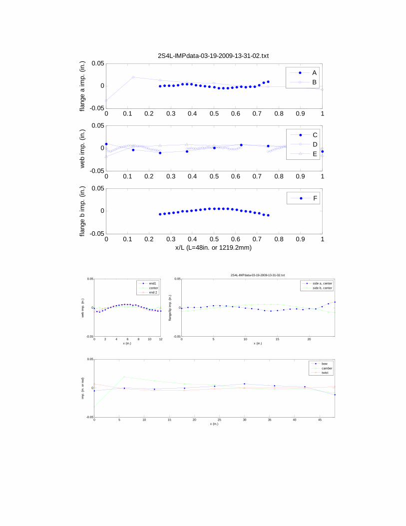
2S4L-IMPdata-03-19-2009-13-31-02.txt
0 0.1 0.2 0.3 0.4 0.5 0.6 0.7 0.8 0.9 1-0.05
0
0.05
web
imp.
(in.
)
0 0.1 0.2 0.3 0.4 0.5 0.6 0.7 0.8 0.9 1-0.05
0
0.05
x/L (L=48in. or 1219.2mm)
flang
e b
imp.
(in.
)
AB
CDE
F
0 2 4 6 8 10 12-0.05
0
0.05
x (in.)
web
imp.
(in.
)
end1centerend 2
0 5 10 15 20-0.05
0
0.05
x (in.)
flang
e/lip
imp.
(in.
)
2S4L-IMPdata-03-19-2009-13-31-02.txt
side a, centerside b, center
0 5 10 15 20 25 30 35 40 45-0.05
0
0.05
x (in.)
imp.
(in.
or r
ad)
bowcambertwist

0 0.1 0.2 0.3 0.4 0.5 0.6 0.7 0.8 0.9 1-0.05
0
0.05
flang
e a
imp.
(in.
)
2S6L-IMPdata-03-19-2009-03-24-18.txt
0 0.1 0.2 0.3 0.4 0.5 0.6 0.7 0.8 0.9 1-0.05
0
0.05
web
imp.
(in.
)
0 0.1 0.2 0.3 0.4 0.5 0.6 0.7 0.8 0.9 1-0.05
0
0.05
x/L (L=72in. or 1828.8mm)
flang
e b
imp.
(in.
)
AB
CDE
F
0 2 4 6 8 10 12-0.05
0
0.05
x (in.)
web
imp.
(in.
)
end1centerend 2
0 5 10 15 20-0.05
0
0.05
x (in.)
flang
e/lip
imp.
(in.
)
2S6L-IMPdata-03-19-2009-03-24-18.txt
side a, centerside b, center
0 10 20 30 40 50 60 70-0.05
0
0.05
x (in.)
imp.
(in.
or r
ad)
bowcambertwist

0 0.1 0.2 0.3 0.4 0.5 0.6 0.7 0.8 0.9 1-0.05
0
0.05
flang
e a
imp.
(in.
)
3S2L-IMPdata-03-21-2009-16-16-41.txt
0 0.1 0.2 0.3 0.4 0.5 0.6 0.7 0.8 0.9 1-0.05
0
0.05
web
imp.
(in.
)
0 0.1 0.2 0.3 0.4 0.5 0.6 0.7 0.8 0.9 1-0.05
0
0.05
x/L (L=24in. or 609.6mm)
flang
e b
imp.
(in.
)
AB
CDE
F
0 2 4 6 8 10 12-0.05
0
0.05
x (in.)
web
imp.
(in.
)
end1centerend 2
0 5 10 15 20-0.05
0
0.05
x (in.)
flang
e/lip
imp.
(in.
)
3S2L-IMPdata-03-21-2009-16-16-41.txt
side a, centerside b, center
0 5 10 15 20-0.05
0
0.05
x (in.)
imp.
(in.
or r
ad)
bowcambertwist

0 0.1 0.2 0.3 0.4 0.5 0.6 0.7 0.8 0.9 1-0.05
0
0.05
flang
e a
imp.
(in.
)
3S4L-IMPdata-03-20-2009-02-00-54.txt
0 0.1 0.2 0.3 0.4 0.5 0.6 0.7 0.8 0.9 1-0.05
0
0.05
web
imp.
(in.
)
0 0.1 0.2 0.3 0.4 0.5 0.6 0.7 0.8 0.9 1-0.05
0
0.05
x/L (L=48in. or 1219.2mm)
flang
e b
imp.
(in.
)
AB
CDE
F
0 2 4 6 8 10 12-0.05
0
0.05
x (in.)
web
imp.
(in.
)
end1centerend 2
0 5 10 15 20-0.05
0
0.05
x (in.)
flang
e/lip
imp.
(in.
)
3S4L-IMPdata-03-20-2009-02-00-54.txt
side a, centerside b, center
0 5 10 15 20 25 30 35 40 45-0.05
0
0.05
x (in.)
imp.
(in.
or r
ad)
bowcambertwist

0 0.1 0.2 0.3 0.4 0.5 0.6 0.7 0.8 0.9 1-0.05
0
0.05
flang
e a
imp.
(in.
)
3S6L-IMPdata-03-20-2009-06-23-46.txt
0 0.1 0.2 0.3 0.4 0.5 0.6 0.7 0.8 0.9 1-0.05
0
0.05
web
imp.
(in.
)
0 0.1 0.2 0.3 0.4 0.5 0.6 0.7 0.8 0.9 1-0.05
0
0.05
x/L (L=72in. or 1828.8mm)
flang
e b
imp.
(in.
)
AB
CDE
F
0 2 4 6 8 10 12-0.05
0
0.05
x (in.)
web
imp.
(in.
)
end1centerend 2
0 5 10 15 20-0.05
0
0.05
x (in.)
flang
e/lip
imp.
(in.
)
3S6L-IMPdata-03-20-2009-06-23-46.txt
side a, centerside b, center
0 10 20 30 40 50 60 70-0.05
0
0.05
x (in.)
imp.
(in.
or r
ad)
bowcambertwist

0 0.1 0.2 0.3 0.4 0.5 0.6 0.7 0.8 0.9 1-0.05
0
0.05
flang
e a
imp.
(in.
)
4S2L-IMPdata-03-21-2009-16-47-11.txt
0 0.1 0.2 0.3 0.4 0.5 0.6 0.7 0.8 0.9 1-0.05
0
0.05
web
imp.
(in.
)
0 0.1 0.2 0.3 0.4 0.5 0.6 0.7 0.8 0.9 1-0.05
0
0.05
x/L (L=24in. or 609.6mm)
flang
e b
imp.
(in.
)
AB
CDE
F
0 2 4 6 8 10 12-0.05
0
0.05
x (in.)
web
imp.
(in.
)
end1centerend 2
0 5 10 15 20-0.05
0
0.05
x (in.)
flang
e/lip
imp.
(in.
)
4S2L-IMPdata-03-21-2009-16-47-11.txt
side a, centerside b, center
0 5 10 15 20-0.05
0
0.05
x (in.)
imp.
(in.
or r
ad)
bowcambertwist

0 0.1 0.2 0.3 0.4 0.5 0.6 0.7 0.8 0.9 1-0.05
0
0.05
flang
e a
imp.
(in.
)
4S4L-IMPdata-03-20-2009-02-39-06.txt
0 0.1 0.2 0.3 0.4 0.5 0.6 0.7 0.8 0.9 1-0.05
0
0.05
web
imp.
(in.
)
0 0.1 0.2 0.3 0.4 0.5 0.6 0.7 0.8 0.9 1-0.05
0
0.05
x/L (L=48in. or 1219.2mm)
flang
e b
imp.
(in.
)
AB
CDE
F
0 2 4 6 8 10 12-0.05
0
0.05
x (in.)
web
imp.
(in.
)
end1centerend 2
0 5 10 15 20-0.05
0
0.05
x (in.)
flang
e/lip
imp.
(in.
)
4S4L-IMPdata-03-20-2009-02-39-06.txt
side a, centerside b, center
0 5 10 15 20 25 30 35 40 45-0.05
0
0.05
x (in.)
imp.
(in.
or r
ad)
bowcambertwist

0 0.1 0.2 0.3 0.4 0.5 0.6 0.7 0.8 0.9 1-0.05
0
0.05
flang
e a
imp.
(in.
)
4S6L-IMPdata-03-20-2009-11-52-53.txt
0 0.1 0.2 0.3 0.4 0.5 0.6 0.7 0.8 0.9 1-0.05
0
0.05
web
imp.
(in.
)
0 0.1 0.2 0.3 0.4 0.5 0.6 0.7 0.8 0.9 1-0.05
0
0.05
x/L (L=72in. or 1828.8mm)
flang
e b
imp.
(in.
)
AB
CDE
F
0 2 4 6 8 10 12-0.05
0
0.05
x (in.)
web
imp.
(in.
)
end1centerend 2
0 5 10 15 20-0.05
0
0.05
x (in.)
flang
e/lip
imp.
(in.
)
4S6L-IMPdata-03-20-2009-11-52-53.txt
side a, centerside b, center
0 10 20 30 40 50 60 70-0.05
0
0.05
x (in.)
imp.
(in.
or r
ad)
bowcambertwist

0 0.1 0.2 0.3 0.4 0.5 0.6 0.7 0.8 0.9 1-0.05
0
0.05
flang
e a
imp.
(in.
)
5S2L-IMPdata-03-21-2009-17-17-03.txt
0 0.1 0.2 0.3 0.4 0.5 0.6 0.7 0.8 0.9 1-0.05
0
0.05
web
imp.
(in.
)
0 0.1 0.2 0.3 0.4 0.5 0.6 0.7 0.8 0.9 1-0.05
0
0.05
x/L (L=24in. or 609.6mm)
flang
e b
imp.
(in.
)
AB
CDE
F
0 2 4 6 8 10 12-0.05
0
0.05
x (in.)
web
imp.
(in.
)
end1centerend 2
0 5 10 15 20-0.05
0
0.05
x (in.)
flang
e/lip
imp.
(in.
)
5S2L-IMPdata-03-21-2009-17-17-03.txt
side a, centerside b, center
0 5 10 15 20-0.05
0
0.05
x (in.)
imp.
(in.
or r
ad)
bowcambertwist

0 0.1 0.2 0.3 0.4 0.5 0.6 0.7 0.8 0.9 1-0.05
0
0.05
flang
e a
imp.
(in.
)
5S4L-IMPdata-03-20-2009-03-37-28.txt
0 0.1 0.2 0.3 0.4 0.5 0.6 0.7 0.8 0.9 1-0.05
0
0.05
web
imp.
(in.
)
0 0.1 0.2 0.3 0.4 0.5 0.6 0.7 0.8 0.9 1-0.05
0
0.05
x/L (L=48in. or 1219.2mm)
flang
e b
imp.
(in.
)
AB
CDE
F
0 2 4 6 8 10 12-0.05
0
0.05
x (in.)
web
imp.
(in.
)
end1centerend 2
0 5 10 15 20-0.05
0
0.05
x (in.)
flang
e/lip
imp.
(in.
)
5S4L-IMPdata-03-20-2009-03-37-28.txt
side a, centerside b, center
0 5 10 15 20 25 30 35 40 45-0.05
0
0.05
x (in.)
imp.
(in.
or r
ad)
bowcambertwist

0 0.1 0.2 0.3 0.4 0.5 0.6 0.7 0.8 0.9 1-0.05
0
0.05
flang
e a
imp.
(in.
)
5S6L-IMPdata-03-20-2009-12-46-54.txt
0 0.1 0.2 0.3 0.4 0.5 0.6 0.7 0.8 0.9 1-0.05
0
0.05
web
imp.
(in.
)
0 0.1 0.2 0.3 0.4 0.5 0.6 0.7 0.8 0.9 1-0.05
0
0.05
x/L (L=72in. or 1828.8mm)
flang
e b
imp.
(in.
)
AB
CDE
F
0 2 4 6 8 10 12-0.05
0
0.05
x (in.)
web
imp.
(in.
)
end1centerend 2
0 5 10 15 20-0.05
0
0.05
x (in.)
flang
e/lip
imp.
(in.
)
5S6L-IMPdata-03-20-2009-12-46-54.txt
side a, centerside b, center
0 10 20 30 40 50 60 70-0.05
0
0.05
x (in.)
imp.
(in.
or r
ad)
bowcambertwist

0 0.1 0.2 0.3 0.4 0.5 0.6 0.7 0.8 0.9 1-0.05
0
0.05
flang
e a
imp.
(in.
)
6S2L-IMPdata-03-22-2009-14-33-23.txt
0 0.1 0.2 0.3 0.4 0.5 0.6 0.7 0.8 0.9 1-0.05
0
0.05
web
imp.
(in.
)
0 0.1 0.2 0.3 0.4 0.5 0.6 0.7 0.8 0.9 1-0.05
0
0.05
x/L (L=24in. or 609.6mm)
flang
e b
imp.
(in.
)
AB
CDE
F
0 2 4 6 8 10 12-0.05
0
0.05
x (in.)
web
imp.
(in.
)
end1centerend 2
0 5 10 15 20-0.05
0
0.05
x (in.)
flang
e/lip
imp.
(in.
)
6S2L-IMPdata-03-22-2009-14-33-23.txt
side a, centerside b, center
0 5 10 15 20-0.05
0
0.05
x (in.)
imp.
(in.
or r
ad)
bowcambertwist

0 0.1 0.2 0.3 0.4 0.5 0.6 0.7 0.8 0.9 1-0.05
0
0.05
flang
e a
imp.
(in.
)
6S4L-IMPdata-03-20-2009-04-18-30.txt
0 0.1 0.2 0.3 0.4 0.5 0.6 0.7 0.8 0.9 1-0.05
0
0.05
web
imp.
(in.
)
0 0.1 0.2 0.3 0.4 0.5 0.6 0.7 0.8 0.9 1-0.05
0
0.05
x/L (L=48in. or 1219.2mm)
flang
e b
imp.
(in.
)
AB
CDE
F
0 2 4 6 8 10 12-0.05
0
0.05
x (in.)
web
imp.
(in.
)
end1centerend 2
0 5 10 15 20-0.05
0
0.05
x (in.)
flang
e/lip
imp.
(in.
)
6S4L-IMPdata-03-20-2009-04-18-30.txt
side a, centerside b, center
0 5 10 15 20 25 30 35 40 45-0.05
0
0.05
x (in.)
imp.
(in.
or r
ad)
bowcambertwist

0 0.1 0.2 0.3 0.4 0.5 0.6 0.7 0.8 0.9 1-0.05
0
0.05
flang
e a
imp.
(in.
)
6S6L-IMPdata-03-20-2009-13-33-15.txt
0 0.1 0.2 0.3 0.4 0.5 0.6 0.7 0.8 0.9 1-0.05
0
0.05
web
imp.
(in.
)
0 0.1 0.2 0.3 0.4 0.5 0.6 0.7 0.8 0.9 1-0.05
0
0.05
x/L (L=72in. or 1828.8mm)
flang
e b
imp.
(in.
)
AB
CDE
F
0 2 4 6 8 10 12-0.05
0
0.05
x (in.)
web
imp.
(in.
)
end1centerend 2
0 5 10 15 20-0.05
0
0.05
x (in.)
flang
e/lip
imp.
(in.
)
6S6L-IMPdata-03-20-2009-13-33-15.txt
side a, centerside b, center
0 10 20 30 40 50 60 70-0.05
0
0.05
x (in.)
imp.
(in.
or r
ad)
bowcambertwist

0 0.1 0.2 0.3 0.4 0.5 0.6 0.7 0.8 0.9 1-0.05
0
0.05
flang
e a
imp.
(in.
)
7S6L-IMPdata-03-20-2009-16-21-40.txt
0 0.1 0.2 0.3 0.4 0.5 0.6 0.7 0.8 0.9 1-0.05
0
0.05
web
imp.
(in.
)
0 0.1 0.2 0.3 0.4 0.5 0.6 0.7 0.8 0.9 1-0.05
0
0.05
x/L (L=72in. or 1828.8mm)
flang
e b
imp.
(in.
)
AB
CDE
F
0 2 4 6 8 10 12-0.05
0
0.05
x (in.)
web
imp.
(in.
)
end1centerend 2
0 5 10 15 20-0.05
0
0.05
x (in.)
flang
e/lip
imp.
(in.
)
7S6L-IMPdata-03-20-2009-16-21-40.txt
side a, centerside b, center
0 10 20 30 40 50 60 70-0.05
0
0.05
x (in.)
imp.
(in.
or r
ad)
bowcambertwist

0 0.1 0.2 0.3 0.4 0.5 0.6 0.7 0.8 0.9 1-0.05
0
0.05fla
nge
a im
p. (i
n.)
61S8L-IMPdata-03-18-2009-15-35-55.txt
0 0.1 0.2 0.3 0.4 0.5 0.6 0.7 0.8 0.9 1-0.05
0
0.05
web
imp.
(in.
)
0 0.1 0.2 0.3 0.4 0.5 0.6 0.7 0.8 0.9 1-0.05
0
0.05
x/L (L=96in. or 2438.4mm)
flang
e b
imp.
(in.
)
AB
CDE
F
0 2 4 6 8 10 12-0.05
0
0.05
x (in.)
web
imp.
(in.
)
end1centerend 2
0 5 10 15 20-0.05
0
0.05
x (in.)
flang
e/lip
imp.
(in.
)
61S8L-IMPdata-03-18-2009-15-35-55.txt
side a, centerside b, center
0 10 20 30 40 50 60 70 80 90-0.05
0
0.05
x (in.)
imp.
(in.
or r
ad)
bowcambertwist

0 0.1 0.2 0.3 0.4 0.5 0.6 0.7 0.8 0.9 1-0.05
0
0.05
flang
e a
imp.
(in.
)
62S8L-IMPdata-03-23-2009-08-29-07.txt
0 0.1 0.2 0.3 0.4 0.5 0.6 0.7 0.8 0.9 1-0.05
0
0.05
web
imp.
(in.
)
0 0.1 0.2 0.3 0.4 0.5 0.6 0.7 0.8 0.9 1-0.05
0
0.05
x/L (L=96in. or 2438.4mm)
flang
e b
imp.
(in.
)
AB
CDE
F
0 2 4 6 8 10 12-0.05
0
0.05
x (in.)
web
imp.
(in.
)
end1centerend 2
0 5 10 15 20-0.05
0
0.05
x (in.)
flang
e/lip
imp.
(in.
)
62S8L-IMPdata-03-23-2009-08-29-07.txt
side a, centerside b, center
0 10 20 30 40 50 60 70 80 90-0.05
0
0.05
x (in.)
imp.
(in.
or r
ad)
bowcambertwist

0 0.1 0.2 0.3 0.4 0.5 0.6 0.7 0.8 0.9 1-0.05
0
0.05
flang
e a
imp.
(in.
)
63S8L-IMPdata-03-23-2009-08-51-42.txt
0 0.1 0.2 0.3 0.4 0.5 0.6 0.7 0.8 0.9 1-0.05
0
0.05
web
imp.
(in.
)
0 0.1 0.2 0.3 0.4 0.5 0.6 0.7 0.8 0.9 1-0.05
0
0.05
x/L (L=96in. or 2438.4mm)
flang
e b
imp.
(in.
)
AB
CDE
F
0 2 4 6 8 10 12-0.05
0
0.05
x (in.)
web
imp.
(in.
)
end1centerend 2
0 5 10 15 20-0.05
0
0.05
x (in.)
flang
e/lip
imp.
(in.
)
63S8L-IMPdata-03-23-2009-08-51-42.txt
side a, centerside b, center
0 10 20 30 40 50 60 70 80 90-0.05
0
0.05
x (in.)
imp.
(in.
or r
ad)
bowcambertwist

0 0.1 0.2 0.3 0.4 0.5 0.6 0.7 0.8 0.9 1-0.05
0
0.05
flang
e a
imp.
(in.
)
64S8L-IMPdata-03-23-2009-09-17-26.txt
0 0.1 0.2 0.3 0.4 0.5 0.6 0.7 0.8 0.9 1-0.05
0
0.05
web
imp.
(in.
)
0 0.1 0.2 0.3 0.4 0.5 0.6 0.7 0.8 0.9 1-0.05
0
0.05
x/L (L=96in. or 2438.4mm)
flang
e b
imp.
(in.
)
AB
CDE
F
0 2 4 6 8 10 12-0.05
0
0.05
x (in.)
web
imp.
(in.
)
end1centerend 2
0 5 10 15 20-0.05
0
0.05
x (in.)
flang
e/lip
imp.
(in.
)
64S8L-IMPdata-03-23-2009-09-17-26.txt
side a, centerside b, center
0 10 20 30 40 50 60 70 80 90-0.05
0
0.05
x (in.)
imp.
(in.
or r
ad)
bowcambertwist

0 0.1 0.2 0.3 0.4 0.5 0.6 0.7 0.8 0.9 1-0.05
0
0.05
flang
e a
imp.
(in.
)
65S8L-IMPdata-03-23-2009-07-21-02.txt
0 0.1 0.2 0.3 0.4 0.5 0.6 0.7 0.8 0.9 1-0.05
0
0.05
web
imp.
(in.
)
0 0.1 0.2 0.3 0.4 0.5 0.6 0.7 0.8 0.9 1-0.05
0
0.05
x/L (L=96in. or 2438.4mm)
flang
e b
imp.
(in.
)
AB
CDE
F
0 2 4 6 8 10 12-0.05
0
0.05
x (in.)
web
imp.
(in.
)
end1centerend 2
0 5 10 15 20-0.05
0
0.05
x (in.)
flang
e/lip
imp.
(in.
)
65S8L-IMPdata-03-23-2009-07-21-02.txt
side a, centerside b, center
0 10 20 30 40 50 60 70 80 90-0.05
0
0.05
x (in.)
imp.
(in.
or r
ad)
bowcambertwist

F) Position Transducer Graphs
0 0.05 0.1 0.15 0.2 0.25 0.3 0.35-1.4
-1.2
-1
-0.8
-0.6
-0.4
-0.2
0
0.2
position (in)
disp
lace
men
t (in
)
1-BARE-BARE-7S6L-6.dat
Position Transducer 1Position Transducer 2Position Transducer 3Position Transducer 4Position Transducer 5
-0.05 0 0.05 0.1 0.15 0.2-0.2
0
0.2
0.4
0.6
0.8
1
1.2
1.4
1.6
1.8
position (in)
disp
lace
men
t (in
)
2-BARE-BARE-1S6L-6,2.txt
Position Transducer 1Position Transducer 2Position Transducer 3Position Transducer 4Position Transducer 5

0 0.05 0.1 0.15 0.2 0.25 0.3 0.35-0.2
0
0.2
0.4
0.6
0.8
1
1.2
1.4
1.6
1.8
position (in)
disp
lace
men
t (in
)
3-BARE-BARE-1S4L-4.dat
Position Transducer 1Position Transducer 2Position Transducer 3Position Transducer 4Position Transducer 5
0 0.05 0.1 0.15 0.2 0.25 0.3 0.35 0.4-0.1
0
0.1
0.2
0.3
0.4
0.5
0.6
0.7
position (in)
disp
lace
men
t (in
)
4-BARE-BARE-1S2L-2.dat
Position Transducer 1Position Transducer 2Position Transducer 3Position Transducer 4Position Transducer 5

-0.05 0 0.05 0.1 0.15 0.2 0.25 0.3 0.35 0.4 0.45-0.5
0
0.5
1
1.5
2
position (in)
disp
lace
men
t (in
)
5-BARE-BARE-1S2LT-2-T.dat
Position Transducer 1Position Transducer 2Position Transducer 3Position Transducer 4Position Transducer 5
0 0.05 0.1 0.15 0.2 0.25 0.3 0.35-1
-0.5
0
0.5
1
1.5
2
2.5
position (in)
disp
lace
men
t (in
)
6-BARE-BARE-2S4LT-4-T.dat
Position Transducer 1Position Transducer 2Position Transducer 3Position Transducer 4Position Transducer 5

-0.05 0 0.05 0.1 0.15 0.2 0.25 0.3-0.5
0
0.5
1
1.5
2
position (in)
disp
lace
men
t (in
)
7-BARE-BARE-2S6LT-6-T.dat
Position Transducer 1Position Transducer 2Position Transducer 3Position Transducer 4Position Transducer 5
-0.1 0 0.1 0.2 0.3 0.4 0.5 0.6-0.2
-0.15
-0.1
-0.05
0
0.05
0.1
0.15
position (in)
disp
lace
men
t (in
)
8-OSB-OSB-3S6LTS-6-T-S.dat
Position Transducer 1Position Transducer 2Position Transducer 3Position Transducer 4Position Transducer 5

-0.1 0 0.1 0.2 0.3 0.4 0.5 0.6 0.7-0.06
-0.04
-0.02
0
0.02
0.04
0.06
0.08
position (in)
disp
lace
men
t (in
)
9-OSB-OSB-4S6LTSP-6-T-S-P.dat
Position Transducer 1Position Transducer 2Position Transducer 3Position Transducer 4Position Transducer 5
-0.1 0 0.1 0.2 0.3 0.4 0.5 0.6-0.06
-0.04
-0.02
0
0.02
0.04
0.06
position (in)
disp
lace
men
t (in
)
10-GYP-GYP-5S6LTSP-6-T-S-P.dat
Position Transducer 1Position Transducer 2Position Transducer 3Position Transducer 4Position Transducer 5

-0.1 0 0.1 0.2 0.3 0.4 0.5 0.6 0.7-0.2
-0.15
-0.1
-0.05
0
0.05
0.1
0.15
position (in)
disp
lace
men
t (in
)
11-GYP-GYP-8S6LTS-6-T-S.dat
Position Transducer 1Position Transducer 2Position Transducer 3Position Transducer 4Position Transducer 5
-0.05 0 0.05 0.1 0.15 0.2 0.25 0.3 0.35 0.4 0.45-2
-1.5
-1
-0.5
0
0.5
1
1.5
2
2.5
position (in)
disp
lace
men
t (in
)
12-OSB-BARE-6S6LTSP-6-T-S-P.dat
Position Transducer 1Position Transducer 2Position Transducer 3Position Transducer 4Position Transducer 5

-0.1 0 0.1 0.2 0.3 0.4 0.5 0.6-0.15
-0.1
-0.05
0
0.05
0.1
0.15
0.2
position (in)
disp
lace
men
t (in
)
13-OSB-GYP-7S6LTSP-6-T-S-P.dat
Position Transducer 1Position Transducer 2Position Transducer 3Position Transducer 4Position Transducer 5
-0.05 0 0.05 0.1 0.15 0.2 0.25 0.3 0.35-0.5
0
0.5
1
1.5
2
position (in)
disp
lace
men
t (in
)
14-OSB-BARE-3S4LTSP-4-T-S-P.dat
Position Transducer 1Position Transducer 2Position Transducer 3Position Transducer 4Position Transducer 5

-0.1 0 0.1 0.2 0.3 0.4 0.5 0.6-0.02
-0.01
0
0.01
0.02
0.03
0.04
0.05
0.06
0.07
0.08
position (in)
disp
lace
men
t (in
)
15-GYP-GYP-4S4LTSP-4-T-S-P.dat
Position Transducer 1Position Transducer 2Position Transducer 3Position Transducer 4Position Transducer 5
-0.2 -0.1 0 0.1 0.2 0.3 0.4 0.5-0.12
-0.1
-0.08
-0.06
-0.04
-0.02
0
0.02
0.04
position (in)
disp
lace
men
t (in
)
16-GYP-OSB-5S4LTSP-4-T-S-P.dat
Position Transducer 1Position Transducer 2Position Transducer 3Position Transducer 4Position Transducer 5

-0.05 0 0.05 0.1 0.15 0.2 0.25 0.3 0.35 0.4 0.45-0.04
-0.03
-0.02
-0.01
0
0.01
0.02
0.03
0.04
position (in)
disp
lace
men
t (in
)17-OSB-OSB-6S4LTSP-4-T-S-P.dat
Position Transducer 1Position Transducer 2Position Transducer 3Position Transducer 4Position Transducer 5
-0.05 0 0.05 0.1 0.15 0.2 0.25 0.3 0.35 0.4-0.04
-0.02
0
0.02
0.04
0.06
0.08
0.1
0.12
0.14
position (in)
disp
lace
men
t (in
)
18-OSB-BARE-4S2LTSP-2-T-S-P.dat
Position Transducer 1Position Transducer 2Position Transducer 3Position Transducer 4Position Transducer 5

-0.2 -0.1 0 0.1 0.2 0.3 0.4 0.5-0.1
0
0.1
0.2
0.3
0.4
0.5
0.6
0.7
0.8
position (in)
disp
lace
men
t (in
)
19-GYP-GYP-3S2LTSP-2-T-S-P.dat
Position Transducer 1Position Transducer 2Position Transducer 3Position Transducer 4Position Transducer 5
-0.15 -0.1 -0.05 0 0.05 0.1 0.15 0.2 0.25 0.3 0.35-0.05
0
0.05
0.1
0.15
0.2
0.25
0.3
0.35
0.4
0.45
position (in)
disp
lace
men
t (in
)
20-OSB-GYP-5S2LTSP-2-T-S-P.dat
Position Transducer 1Position Transducer 2Position Transducer 3Position Transducer 4Position Transducer 5

-0.2 -0.1 0 0.1 0.2 0.3 0.4 0.5-0.04
-0.02
0
0.02
0.04
0.06
0.08
0.1
0.12
0.14
position (in)
disp
lace
men
t (in
)
21-OSB-OSB-6S2LTSP-2-T-S-P.dat
Position Transducer 1Position Transducer 2Position Transducer 3Position Transducer 4Position Transducer 5
0 0.05 0.1 0.15 0.2 0.25 0.3 0.35 0.4-1.2
-1
-0.8
-0.6
-0.4
-0.2
0
0.2
position (in)
disp
lace
men
t (in
)
22-BARE-BARE-61S8LTP-8-T-P,2.txt
Position Transducer 1Position Transducer 2Position Transducer 3Position Transducer 4Position Transducer 5String Pot 3String Pot 4

-0.05 0 0.05 0.1 0.15 0.2 0.25 0.3 0.35-0.2
-0.15
-0.1
-0.05
0
0.05
0.1
0.15
0.2
0.25
position (in)
disp
lace
men
t (in
)
23-OSB-BARE-62S8LTSP-8-T-S-P,2.txt
Position Transducer 1Position Transducer 2Position Transducer 3Position Transducer 4Position Transducer 5String Pot 3String Pot 4
0.05 0.1 0.15 0.2 0.25 0.3 0.35 0.4 0.45 0.5 0.55-0.2
-0.15
-0.1
-0.05
0
0.05
0.1
0.15
position (in)
disp
lace
men
t (in
)
24-OSB-GYP-63S8LTSP-8-T-S-P,2.txt
Position Transducer 1Position Transducer 2Position Transducer 3Position Transducer 4Position Transducer 5String Pot 3String Pot 4

0 0.1 0.2 0.3 0.4 0.5 0.6 0.7-0.4
-0.3
-0.2
-0.1
0
0.1
0.2
0.3
0.4
position (in)
disp
lace
men
t (in
)
25-GYP-GYP-64S8LTSP-8-T-S-P,2.txt
Position Transducer 1Position Transducer 2Position Transducer 3Position Transducer 4Position Transducer 5String Pot 3String Pot 4
0 0.1 0.2 0.3 0.4 0.5 0.6 0.7-0.2
-0.1
0
0.1
0.2
0.3
0.4
0.5
0.6
position (in)
disp
lace
men
t (in
)
26-OSB-OSB-65S8LTSP-8-T-S-P,2.txt
Position Transducer 1Position Transducer 2Position Transducer 3Position Transducer 4Position Transducer 5String Pot 3String Pot 5

G) Data from coupon test and measurements
Specimentcoated-average
(in.)t1 t2 t3 taverage b1 b2 b3 baverage
fy (0.2% offset)
(ksi)fy (autographic method)
(ksi)fu (ksi) Δu (in./in.)
1S4L 0.0675 0.0655 0.0655 0.066 0.0657 0.487 0.487 0.487 0.4870 55.9 57.4 79.38 0.172S4L 0.0675 0.065 0.0655 0.0655 0.0653 0.4865 0.4875 0.487 0.4870 54.7 56.1 77.59 0.183S4L 0.0675 0.0655 0.0655 0.066 0.0657 0.487 0.4875 0.487 0.4872 55.6 57.1 78.92 0.161S6L 0.0675 0.0655 0.066 0.0655 0.0657 0.487 0.487 0.4875 0.4872 54.9 56.1 77.99 0.162S6L 0.0675 0.066 0.0655 0.0655 0.0657 0.4875 0.487 0.497 0.4905 55.3 56.4 78.78 0.206S6L* 0.0675 0.0655 0.0655 0.0655 0.0655 0.487 0.487 0.4865 0.4868 55.3 56 79.21 0.247S6L* 0.0675 0.0655 0.0655 0.0655 0.0655 0.487 0.4875 0.487 0.4872 56.4 56.7 79.69 0.2461S8L 0.0675 0.0655 0.0655 0.0655 0.0655 0.487 0.4875 0.4865 0.4870 56.2 57 79.48 0.21
mean 0.0675 0.0656 0.4875 55.54 56.6 78.88 0.19COV 0.000 0.003 0.004 0.011 0.009 0.009 0.163
1T-1S8L* 0.08 0.078 0.078 0.077 0.0777 0.487 0.4875 0.488 0.4875 70.7 68.5 77.64 0.241T-2S8L* 0.08 0.0775 0.078 0.078 0.0778 0.487 0.487 0.488 0.4873 70.7 69.7 78.39 0.24
mean 0.08 0.0778 0.4874 70.70 69.1 78.02 0.24COV 0.000 0.005 0.001 0.000 0.012 0.007 0.001
* Specimen that failed inside the gauge length (length covered by extensometer)
Δu (in./in.) - the big value of COV for Δu is due to the position of the extensometer compared to where it fails. If the crack is in the gauge length, Δu is bigger than if it is outside the gauge length.
Stud
Track
t bare (in.) b bare (in.)
H) Yielding stress (Studs)
0 0.05 0.1 0.15 0.2 0.250
10
20
30
40
50
60
70
80
90
Engineering Strain,(in./in.)
Axia
l Ten
sile
Stre
ss (k
si)
1S4L.txt
fy (0.2% offset)=55.9 ksi
0 0.05 0.1 0.15 0.2 0.250
10
20
30
40
50
60
70
80
90
Engineering Strain,(in./in.)
Axia
l Ten
sile
Stre
ss (k
si)
2S4L.txt
fy (0.2% offset)=54.7 ksi
0 0.05 0.1 0.15 0.2 0.250
10
20
30
40
50
60
70
80
90
Engineering Strain,(in./in.)
Axia
l Ten
sile
Stre
ss (k
si)
3S4L.txt
fy (0.2% offset)=55.6 ksi
0 0.05 0.1 0.15 0.2 0.250
10
20
30
40
50
60
70
80
90
Engineering Strain,(in./in.)
Axia
l Ten
sile
Stre
ss (k
si)
1S6L.txt
fy (0.2% offset)=54.9 ksi
0 0.05 0.1 0.15 0.2 0.250
10
20
30
40
50
60
70
80
90
Engineering Strain,(in./in.)
Axia
l Ten
sile
Stre
ss (k
si)
2S6L.txt
fy (0.2% offset)=55.3 ksi
0 0.05 0.1 0.15 0.2 0.250
10
20
30
40
50
60
70
80
90
Engineering Strain,(in./in.)
Axia
l Ten
sile
Stre
ss (k
si)
6S6L.txt
fy (0.2% offset)=55.3 ksi
0 0.05 0.1 0.15 0.2 0.250
10
20
30
40
50
60
70
80
90
Engineering Strain,(in./in.)
Axia
l Ten
sile
Stre
ss (k
si)
7S6L.txt
fy (0.2% offset)=56.4 ksi
0 0.05 0.1 0.15 0.2 0.250
10
20
30
40
50
60
70
80
90
Engineering Strain,(in./in.)
Axia
l Ten
sile
Stre
ss (k
si)
61S8L.txt
fy (0.2% offset)=56.2 ksi
i) Yielding stress determined using 0.2% offset method (Studs)

0 0.05 0.1 0.15 0.2 0.250
20
40
60
80
100
Engineering Strain (in./in.)
Axia
l Ten
sile
Stre
ss (k
si)
1S4L.txt
fy (Autographic Method)=57.4 ksi
0 0.05 0.1 0.15 0.2 0.250
20
40
60
80
100
Engineering Strain (in./in.)
Axia
l Ten
sile
Stre
ss (k
si)
2S4L.txt
fy (Autographic Method)=56.1 ksi
0 0.05 0.1 0.15 0.2 0.250
20
40
60
80
100
Engineering Strain (in./in.)
Axia
l Ten
sile
Stre
ss (k
si)
3S4L.txt
fy (Autographic Method)=57.1 ksi
0 0.05 0.1 0.15 0.2 0.250
20
40
60
80
100
Engineering Strain (in./in.)
Axia
l Ten
sile
Stre
ss (k
si)
1S6L.txt
fy (Autographic Method)=56.1 ksi
0 0.05 0.1 0.15 0.2 0.250
20
40
60
80
100
Engineering Strain (in./in.)
Axia
l Ten
sile
Stre
ss (k
si)
2S6L.txt
fy (Autographic Method)=56.4 ksi
0 0.05 0.1 0.15 0.2 0.250
20
40
60
80
100
Engineering Strain (in./in.)
Axia
l Ten
sile
Stre
ss (k
si)
6S6L.txt
fy (Autographic Method)=56 ksi
0 0.05 0.1 0.15 0.2 0.250
20
40
60
80
100
Engineering Strain (in./in.)
Axia
l Ten
sile
Stre
ss (k
si)
7S6L.txt
fy (Autographic Method)=56.7 ksi
0 0.05 0.1 0.15 0.2 0.250
20
40
60
80
100
Engineering Strain (in./in.)
Axia
l Ten
sile
Stre
ss (k
si)
61S8L.txt
fy (Autographic Method)=57 ksi
ii) Yielding stress determined using autographic method (Studs)
I) Yielding stress (Tracks)
0 0.05 0.1 0.15 0.2 0.250
10
20
30
40
50
60
70
80
90
Engineering Strain,(in./in.)
Axia
l Ten
sile
Stre
ss (k
si)
1T-1S8L.txt
fy (0.2% offset)=70.7 ksi
0 0.05 0.1 0.15 0.2 0.250
10
20
30
40
50
60
70
80
90
Engineering Strain,(in./in.)
Axia
l Ten
sile
Stre
ss (k
si)
1T-2S8L.txt
fy (0.2% offset)=70.7 ksi
i) Yielding stress determined using 0.2% offset method (Tracks)

0 0.05 0.1 0.15 0.2 0.250
10
20
30
40
50
60
70
80
90
100
Engineering Strain (in./in.)
Axia
l Ten
sile
Stre
ss (k
si)
1T-1S8L.txt
fy (Autographic Method)=68.5 ksi
0 0.05 0.1 0.15 0.2 0.250
10
20
30
40
50
60
70
80
90
100
Engineering Strain (in./in.)
Axia
l Ten
sile
Stre
ss (k
si)
1T-2S8L.txt
fy (Autographic Method)=69.7 ksi
ii) Yielding stress determined using autographic method (Tracks)