Compression cutting test for rubber - NIST...
12
U.S. Department of Commerce Bureau of Standards RESEARCH PAPER RP674 Part of Bureau of Standards Journal of Research, vol. 12, April 1934 COMPRESSION CUTTING TEST FOR RUBBER By W. L. Holt ABSTRACT This paper describes a study of the compression cutting test, also referred to as the shear test, for rubber. The test consists of compressing a sample of rubber to failure between a flat plate or anvil and a cutting tool, and recording the rela- tion between the thickness of the sample and the load up to failure. Data are presented on (1) different tools used for the test, (2) conditions affecting the re- sults, and (3) a comparison of the compression cutting tests with other common tests. Advantages and disadvantages of the compression cutting test are discussed. The conclusion is reached that it is valuable as a supplement to, rather than as a substitute for, the tensile test. CONTENTS Page I. Introduction 489 II. Description of machine and nature of test 490 III. Compression cutting tools 491 IV. Conditions affecting test 492 1. Adjustment of tool 492 2. Lubrication 493 3. Dimensions of test specimen 493 4. Temperature 494 V. Compression cutting tests of typical compounds 495 VI. Comparison with other tests 497 VII. The compression cutting test as a measure of aging 497 VIII. Application of compression cutting test to specifications 498 IX. Conclusion 499 I. INTRODUCTION Compression tests for insulated wire were described by Hippensteel in 1926. 1 Later Ingmanson and Gray 2 and Somerville 3 described a machine for making compression cutting and shear tests as applied not only to insulation for wire but to rubber in general. The test consists of compressing a sample between a flat plate or anvil and a cutting tool. The relation between the thickness under the cutting tool and the load is recorded graphically. The test has a strong appeal because it is much simpler to make than tensile-strength tests and data have been presented indicating that it may be a satisfactory substi- tute for the tensile test. The work described in the present paper was carried on in order to obtain information concerning the test with a view to employing it in specifications. i Ind. Eng. Chem., vol. 18, pp. 409-411, 1926. 2 India Rubber World, vol. 82, no. 4, pp. 53-58, July 1, 1930. 3 Inst. Rubber Ind., Trans., vol. 6, no. 2, pp. 150-159, 1930. 489
-
Upload
trinhkhanh -
Category
Documents
-
view
217 -
download
1
Transcript of Compression cutting test for rubber - NIST...

U.S. Department of Commerce Bureau of Standards
RESEARCH PAPER RP674
Part of Bureau of Standards Journal of Research, vol. 12, April 1934
COMPRESSION CUTTING TEST FOR RUBBER
By W. L. Holt
ABSTRACT
This paper describes a study of the compression cutting test, also referred to asthe shear test, for rubber. The test consists of compressing a sample of rubberto failure between a flat plate or anvil and a cutting tool, and recording the rela-
tion between the thickness of the sample and the load up to failure. Data arepresented on (1) different tools used for the test, (2) conditions affecting the re-
sults, and (3) a comparison of the compression cutting tests with other commontests. Advantages and disadvantages of the compression cutting test are discussed.The conclusion is reached that it is valuable as a supplement to, rather than asa substitute for, the tensile test.
CONTENTS Page
I. Introduction 489II. Description of machine and nature of test 490
III. Compression cutting tools 491IV. Conditions affecting test 492
1. Adjustment of tool 4922. Lubrication 4933. Dimensions of test specimen 4934. Temperature 494
V. Compression cutting tests of typical compounds 495VI. Comparison with other tests 497
VII. The compression cutting test as a measure of aging 497VIII. Application of compression cutting test to specifications 498IX. Conclusion 499
I. INTRODUCTION
Compression tests for insulated wire were described by Hippensteelin 1926. 1 Later Ingmanson and Gray 2 and Somerville 3 described amachine for making compression cutting and shear tests as appliednot only to insulation for wire but to rubber in general. The test
consists of compressing a sample between a flat plate or anvil and acutting tool. The relation between the thickness under the cutting
tool and the load is recorded graphically. The test has a strong appealbecause it is much simpler to make than tensile-strength tests and datahave been presented indicating that it may be a satisfactory substi-
tute for the tensile test. The work described in the present paper wascarried on in order to obtain information concerning the test with aview to employing it in specifications.
i Ind. Eng. Chem., vol. 18, pp. 409-411, 1926.2 India Rubber World, vol. 82, no. 4, pp. 53-58, July 1, 1930.3 Inst. Rubber Ind., Trans., vol. 6, no. 2, pp. 150-159, 1930.
489

490 Bureau oj Standards Journal of Research [Vol. 12
II. DESCRIPTION OF MACHINE AND NATURE OF TEST
The machine used for the tests was the same as used by Ingmansonand Gray, and by Somerville. (See fig. 1.) It consists essentially of
a means for compressing rubber samples between a cutting tool anda steel anvil and measuring the load and thickness under the tool.
The tool is fixed at the top of the machine and the anvil carrying thesample is forced up against it as indicated. The load is applied througha heavy coil spring, the compression of which is used to measure theload. The lower end of this spring travels at a speed of 1.5 inches perminute. The compression of the spring (i.e., the load), together withthe distance between the tool and the anvil (i.e., the thickness of the
2000 LOADLQAD-TH(Q<NE$$
CHART
=zf MOTOR \
Figure 1.
—
Machine for compression cutting tests.
specimen), are recorded mechanically on a chart as a load-thickness
curve. The maximum capacity of the machine is 2,000 pounds.Cutting does not take place gradually as is the case with many
materials. Instead, the rubber is compressed to a fraction of the orig-
inal thickness before any cutting occurs. When cutting does start, it
takes place suddenly and, due to the design of the machine, the speci-
men is cut completely through.The property of a rubber compound measured by the test is not a
simple one. The rubber is first crowded away from each side of the
cutting tool, thus introducing stresses at an angle to the section beingcut. The top surface of the sample is put in tension as indicated bythe deformation of the surface, and frictional resistance between the
rubber and the tool and anvil introduces stresses. The test is often
referred to as shear, but in the present paper the expression " com-pression cutting", or simply cutting, is used as being a truer descrip-

Holt] Compression Cutting Test j"or Rubber 491
tion. The test may be classed as a performance test in that it repre-
sents a condition which rubber may be called upon to resist in service.
A relatively small quantity of material is required for test purposes,
specimens are ordinarily easy to prepare, and small differences in the
thickness of specimens have relatively little effect on the cutting load.
Test specimens of insulation from wires and cables consist simply of
longitudinal sections of the insulation about 1 inch long. Rubberin sheet form may be conveniently tested, a piece 1 by 2 inches
sufficing for 6 or 8 tests.
III. COMPRESSION CUTTING TOOLS
A variety of ways of cutting have been tried out with the machine.When insulated wire containing a solid conductor is tested, it is satis-
factory to compress the wire between two flat anvils. In this case,
cutting takes place between the conductor and the anvils. However,this method cannot be used for a cable having a stranded conductor,
nor is it applicable to the testing of sheet rubber. For tests of
insulation from a stranded conductor, the insulation may be split
longitudinally and the test made on a portion of the insulation
between a flat anvil and a mandrel equivalent to the original wire size.
For simplicity, however, there is an advantage in one tool for all tests,
i.e., all sizes of wire, sheet rubber, etc.
A 90° steel wedge with the edge flattened to a width of 0.008 inchhas been used elsewhere and was tried out for our work. (See fig. 2.)
Questions arose, however, as to the necessary limits for the width of
the flattened edge and how to define the sharpness of the two edgesresulting from the flattening process. A series of wedges was made as
nearly identical as possible except for the width of the flattened edges.
These varied from 0.0008 to 0.0098 inch. Cutting tests were thenmade on five different compounds. The results are shown in figure
2. Duplicate tests were made with the samples dry and whenlubricated with a mixture of glycerine and graphite. In both cases
the relation between the width of the cutting edge and the cuttingload is,very nearly linear. A change in width of the cutting edge doesnot affect all compounds the same. The average for the dry tests
with wedges in the region of 0.008-inch width is about 100 poundsdifference in cutting load per 0.001-inch difference in width. Withthe lubricated samples it is about 85 pounds instead of 100 pounds.An examination of wedges with a microscope after 40 or 50 tests
showed considerable scratching of the surfaces, and a decided dulling,
apparently due to high concentration of load on the edges of theflattened portion during a test. Attempts which were made to
construct duplicate wedges indicated that considerable difficulty
would be experienced in making them with equal cutting character-istics.
On the basis of these tests the 90° wedge was abandoned and atool was made with an edge which can be more easily defined andrenewed. This tool consists of an acute-angle wedge grooved alongits edge to hold a piece of 1-millimeter drill rod. The tool and thecorresponding anvil are shown in figure 3. Experience has shownthat the tool can be easily duplicated and that by renewing the drill
rod when there is an appreciable wear, a constant cutting edge is
maintained. From the standpoint of cutting, the tool is equivalentto the mandrels used by Ingmanson and Gray. No precise data

492 Bureau of Standards Journal of Research [Vol. it
have been obtained on the life of the cutting edge, but with ordinarygrades of rubber, 100 tests per edge seem to be feasible. Stops are
provided on each side of the cutting tool. These are set for a clear-
ance of 0.002 inch between the tool and the anvil so as to avoiddamage to the edge.
.004 .006 .008WIDTH OF EDGE IN.
.010
Figure 2.
—
Relation of width of edge face to the compression cutting load.
Five different compounds were tested as follows:
K—Pure gum, ultra accelerator.
L—Tread stock, 30 parts carbon.M—Superaging compound 80 percent rubber by volume.N—Tread stock, 50 parts carbon.P—Loaded stock, 100 parts soft carbon.
In upper set samples were lubricated with glycerine and graphite. In lower set they were tested dry.
IV. CONDITIONS AFFECTING TEST1. ADJUSTMENT OF TOOL
Care must be taken to insure that the tool and anvil face are par-allel as otherwise low cutting loads result. The necessary limits for
parallelism will depend upon the type of rubber tested and on its
thickness. Tests show that for ordinary purposes the tool and theanvil should not be out of parallel by more than 0.001 inch. Thethinner the sample and the more compressible the rubber, the greaterwill be the influence of any departure from parallelism.

B.S. Journal of Research, RP674
Figure 3.
—
Tool and anvil used in compression cutting tests.
Stops are set for .002" clearance between tool and anvil so as to avoid damage to edge.
Holt] Compression Cutting Test for Rubber 493
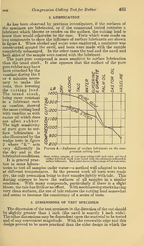
2. LUBRICATION
As has been observed by previous investigators, if the surfaces of
the specimen are lubricated, or if the compound tested contains a
lubricant which blooms or exudes on the surface, the cutting load is
lower than would otherwise be the case. Tests which were made ontwo compounds to show the influence of surface lubricants are shownin figure 4. When alcohol and water were employed, a container wasconstructed around the anvil, and tests were made with the samplecompletely submerged. In the other cases the tool and the anvil andboth sides of the sample were coated with the lubricant.
The pure gum compound is more sensitive to surface lubrication
than the tread stock. It also appears that the surface of the pure
gum rubbermay havebeen attacked by the
vaseline during the 3
or 4 minutes neces-
sary to make the
tests, thus loweringthe cutting load.The tread stock,being more resistant
to a lubricant suchas vaseline, showedthe same cutting loadwith vaseline as withcastor oil which doesnot affect rubber.The high sensitivity
of pure gum to sur-
face lubrication is
also illustrated by thewedge tests in figure
2 where "K" acts
very differently in
the dry and in thelubricated conditions.
It is general prac-tice in some labora-tories to test all samples under water—a method well adapted to tests
at different temperatures. In the present work all tests were madedry, the only precaution being to dust samples lightly with talc. Thisdusting appears to leave the surfaces of all samples in a similar
condition. With many compounds, particularly if there is a slight
bloom, the talc has little or no effect. With nonblooming stocks havingvery clean surfaces, the use of talc reduces the cutting load somewhatand seems to increase the consistency of a series of tests.
psoo
•5/200
Figure 4.- -Infiuence of surface lubricants on the com-pression cutting load.
Sheet rubber samples of pure gum rubber 0.087 inch thick and treadrubber 0.075 inch thick were tested with the substances indicated assurface lubricants. Each point shown is the average of 5 or more tests.
3. DIMENSIONS OF TEST SPECIMEN
The dimension of the test specimen in the direction of the cut shouldbe slightly greater than 1 inch (the anvil is exactly 1 inch wide).The other dimensions may be dependent upon the material to be testedand of any convenient magnitude. With the renewable edge tool this
design proved to be more practical than the older design in which the

494 Bureau of Standards Journal of Research [Vol. 12
cutting face was made an exact length, the method used with the wedgeand other tools.
The thickness of the sample will affect the cutting load, but, as
indicated previously, not in direct proportion to the thickness. Dataon the effect of thickness are shown in figure 5. Tests were made oneight rubber compounds, subsequently described, each compoundbeing cured in sheets of four thicknesses. Results reported by Somer-ville, and by Ingmanson and Gray are indicated in the figure by brokenlines. There is some variation in the effect of thickness of different
types of rubber on the cutting load, but as an average the load in-
creases 25 to 35 percent for an increase of 100 percent in thickness.
0.2 04 06 08THICKNESS
10 12 .14 IN.
Figure 5.
—
Influence of thickness of sample on the compression cutting load.
Eight different compounds were tested (see table 1) with the tool shown in figure 3. Each point on thecurve is the average of from 4 to 8 tests.
A. 30-percent insulation.B. 40-percent insulation.C. Low quality insulation.D. 40 parts gas black stock.E. 40 parts thermatomic carbon stock.F. Pure gum plus 10 volumes kalite.
Q. Pure gum, ultra accelerator.H. Pure gum.Broken line "S" shows results reported by Somerville with a wedge tool.Dot-dash line "I" shows results reported by Ingmanson and Gray with a mandrel.
4. TEMPERATURE
Somerville has reported some data on the effect of temperature,which indicates that the compression cutting load and the tensile
strength are affected similarly. In the present work all tests weremade at a constant temperature of 75 F, and no data are presentedon the effect of temperature.

Holt) Compression Cutting Test jor Rubber 495
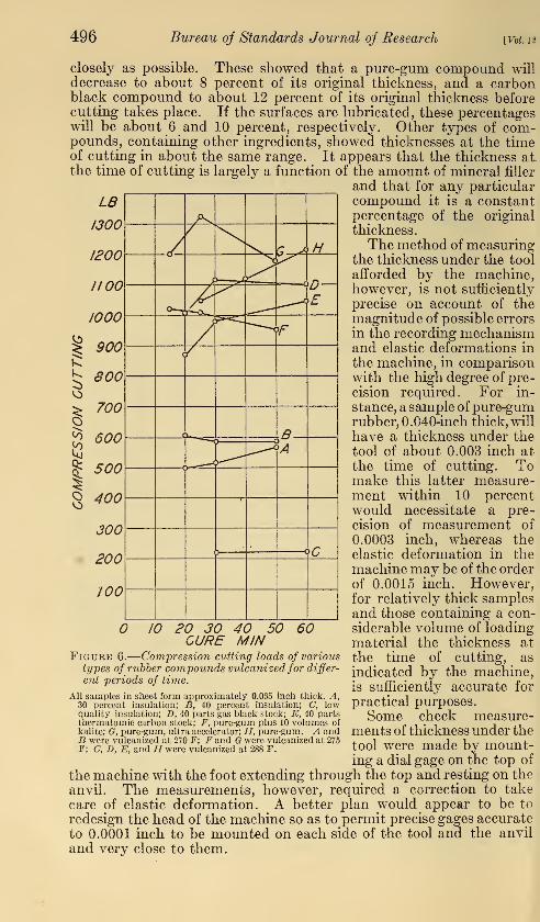
V. COMPRESSION CUTTING TESTS OF TYPICALCOMPOUNDS
For a study of the compression cutting test as a means of classify-
ing different types of rubber the eight compounds shown in table 1
were prepared in the form of sheets, several cures of each compoundbeing made. The results of tests on these compounds are shownin figure 6.
Table 1.
—
Composition of compounds tested
Ingredient
Composition (parts by weight) of compounds—
A> B2 C3 D E F G H
Rubber 1004.637.0176.0
1004.032.6104.4
25011.7215.60
594.0
1003
5
1003
5
1002
2
10022
100Sulphur 3Zinc oxide 2
Whiting ..
Kaliteno.3 4 . 26.0.25Tetramethylthiuramdisulphide .25
40"Thermatornic" (carbon black).. 40
41
.85
Stearic acid 3.91
"~Tl3~235.0
4
1
.85
V.G.B. (antioxidant) .5 .5MercaptobenzothiazoleMineral rubberTetramethylthiurammonosulphide .4 .3
5.5ParaffinOzokerite 4.1
8.2ReiYlaimpd rubber 250.0
235.0ClayDiphenylguanidine . .75
1 30 percent insulation. 2 40 percent insulation. s Code wire. 4 Specially processed calcium carbonate.
The accelerated pure-gum compounds G and H give the highest cut-
ting loads. Ten or fifteen percent below the pure-gum compoundsare D, E, and F, all containing fillers and consisting, respectively,
of 40 parts of reinforcing carbon black, 40 parts of nonreinforcingcarbon black, and 26 parts of kalite, a specially processed calciumcarbonate. D, the tread type of compound, has a slightly highercutting load than the other two compounds.B and A are respectively 40 and 30 percent rubber insulation
compounds. The cutting load of B is lowered by its paraffin content.Compound C is low in rubber and high in asphaltic materials and otheringredients and shows a low cutting load. Cure affects the cuttingload in much the same way that it affects tensile strength.The cutting load itself is not particularly sensitive in distinguishing
among different types of compounds as evidenced by the relatively
small differences among the five highest compounds that differ verymaterially in composition. It would appear that in order to dis-
tinguish among them some other factor should be taken into con-sideration, such as the thickness under the tool at the time of cuttingor the rate of decrease in thickness with load. This conclusion is in
line with tensile tests where elongation and stiffness, together withtensile strength, are used in attempting to define a compound.Although the design of this machine is such that the thickness
under^ the tool during compression is indicated graphically, theprecision of the measurement for highly compressible rubber, partic-
ularly if thin, is not very great. However, several measurements of
thickness under the tool at the instant of cutting were determined as
43437—34 7
496 Bureau oj Standards Journal oj Research [Vol. 12
closely as possible. These showed that a pure-gum compound will
decrease to about 8 percent of its original thickness, and a carbonblack compound to about 12 percent of its original thickness beforecutting takes place. If the surfaces are lubricated, these percentageswill be about 6 and 10 percent, respectively. Other types of com-pounds, containing other ingredients, showed thicknesses at the timeof cutting in about the same range. It appears that the thickness atthe time of cutting is largely a function of the amount of mineral filler
and that for any particular
I
S
I
LB
1300
1200
Jtoo
1000
900
800
700
600
500
400
300
200
100
A*
//
H; 1—AAvt^
>r
tV\
bA
^"—'
-<3 c
> ' (>C
compound it is a constantpercentage of the original
thickness.
The method of measuringthe thickness under the tool
afforded by the machine,however, is not sufficiently
precise on account of themagnitude of possible errors
in the recording mechanismand elastic deformations in
the machine, in comparisonwith the high degree of pre-
cision required. For in-
stance, a sample of pure-gumrubber, 0.040-inch thick, will
have a thickness under thetool of about 0.003 inch at
the time of cutting. Tomake this latter measure-ment within 10 percentwould necessitate a pre-
cision of measurement of
0.0003 inch, whereas theelastic deformation in themachine may be of the orderof 0.0015 inch. However,for relatively thick samplesand those containing a con-siderable volume of loadingmaterial the thickness at
the time of cutting,_as
indicated by the machine,is sufficiently accurate for
practical purposes.Some check measure-
ments of thickness under the
tool were made by mount-ing a dial gage on the top of
the machine with the foot extending through the top and resting on the
anvil. The measurements, however, required a correction to take
care of elastic deformation. A better plan would appear to be to
redesign the head of the machine so as to permit precise gages accurate
to 0.0001 inch to be mounted on each side of the tool and the anvil
and very close to them.
10 6020 30 40 50CURE MIN
Figure 6.
—
Compression cutting loads of varioustypes of rubber compounds vulcanized for differ-
ent periods of time.
All samples in sheet form approximately 0.065 inch thick. A,30 percent insulation; B, 40 percent insulation; C, lowquality insulation; D, 40 parts gas black stock; E, 40 partsthermatomic carbon stock; F, pure-gum plus 10 volumes of
kalite; G, pure-gum, ultra accelerator; H, pure-gum. A andB were vulcanized at 270 F; F and G were vulcanized at 275F; C, D, E, and H were vulcanized at 288 F.
Holt] Compression Cutting Testfor Rubber 497
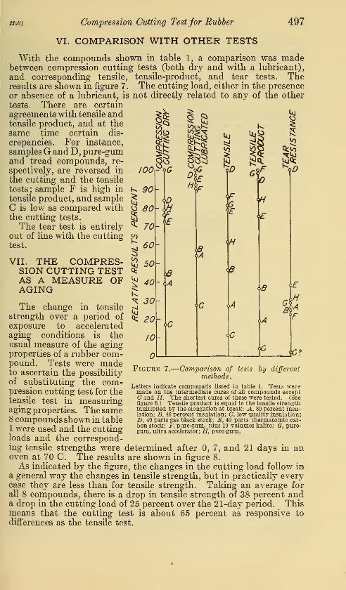
VI. COMPARISON WITH OTHER TESTS
With the compounds shown in table 1, a comparison was madebetween compression cutting tests (both dry and with a lubricant),
and corresponding tensile, tensile-product, and tear tests. Theresults are shown in figure 7. The cutting load, either in the presence
or absence of a lubricant, is not directly related to any of the othertests. There are certain
|l
/OOr?G
1
si
90
80
70
60
50
40
30
20
10
H\
I
A
hC
90
r <W
\H
&hB
hA
agreements with tensile andtensile product, and at thesame time certain dis-
crepancies. For instance,
samplesG and D, pure-gumand tread compounds, re-
spectively, are reversed in
the cutting and the tensile
tests; sample F is high in
tensile product, and sampleC is low as compared withthe cutting tests.
The tear test is entirely
out of line with the cuttingtest.
VII. THE COMPRES-SION CUTTING TESTAS A MEASURE OFAGING
The change in tensile
strength over a period of
exposure to acceleratedaging conditions is theusual measure of the agingproperties of a rubber com-pound. Tests were madeto ascertain the possibility
of substituting the com-pression cutting test for thetensile test in measuringaging properties. The same8 compounds shown in table1 were used and the cutting-
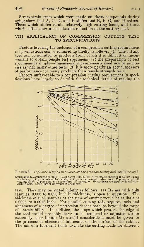
loads and the correspond-ing tensile strengths were determined after 0, 7, and 21 days in anoven at 70 C. The results are shown in figure 8.
As indicated by the figure, the changes in the cutting load follow ina general way the changes in tensile strength, but in practically everycase they are less than for tensile strength. Taking an average forall 8 compounds, there is a drop in tensile strength of 38 percent anda drop in the cutting load of 25 percent over the 21-day period. Thismeans that the cutting test is about 65 percent as responsive todifferences as the tensile test.
<C
Figure 7. -Comparison ofmethods
.
tests by different
Letters indicate compounds listed in table 1. Tests weremade on the intermediate cures of all compounds exceptC and H. The shortest cures of these were tested. (Seefigure 6 ) Tensile product is equal to the tensile strengthmultiplied by the elongation at break: A, 30 percent insu-lation; B, 40 percent insulation; C, low quality insulation;D, 40 parts gas black stock; E, 40 parts thermatomic car-bon stock; F, pure-gum, plus 10 volumes kalite; O, pure-gum, ultra accelerator; H, pure-gum.
498 Bureau of Standards Journal of Research [Vol. It
Stress-strain tests which were made on these compounds duringaging show that A, C, D, and E stiffen and B, F, G, and H soften.
Those which stiffen retain relatively high cutting loads, and thosewhich soften show a considerable reduction in the cutting load.
VIII. APPLICATION OF COMPRESSION CUTTING TESTTO SPECIFICATIONS
Factors favoring the inclusion of a compression cutting requirementin specifications can be summed up briefly as follows: (1) The cutting
test can be adapted to products from which it is difficult or incon-venient to obtain tensile test specimens; (2) the preparation of test
specimens is simple—dimensional measurements need not be as pre-
cise as with many other tests; (3) it is more nearly an actual measureof performance for many products than tensile strength tests.
Factors unfavorable to a compression cutting requirement in speci-
fications have largely to do with the technical details of making the
4 6 8 10 12 14 16 18 20DAYS IN OVEN A T 7CTC
Figure 8.
—
Influence of aging in an oven on compression cutting and tensile strength:
Letters refer to compounds in table 1: A, 30 percent insulation; B, 40 percent insulation; C, low qualityinsulation; D, 40 parts carbon black stock; E, 40 parts thermatomic carbon stock; F, pure-gum plus 10
volumes kalite; O, pure-gum, ultra accelerator; H, pure-gum. Heavy lines show results of compressioncutting tests. Light lines show results of tensile tests.
test. They may be stated briefly as follows: (1) Its use with thin
samples, 0.006 to 0.020 inch in thickness, is open to question. Thethickness of such samples at the time of cutting would be as little as
0.0005 to 0.0016 inch. For parallel cutting this requires tools andalinement of a degree of perfection that is perhaps beyond the rangeof practicability. In addition, the stops which protect the edge of
the tool would probably have to be removed or adjusted withinextremely close limits; (2) careful consideration must be given to
the presence or absence of lubricants on the surface of the rubber.
The use of a lubricant tends to make the cutting loads for different

fiott] Compression Cutting Test for Rubber 499
types of compounds more nearly the same and reduces the sensitivity
of the test; (3) as a criterion of aging in an oven, the cutting test is
less responsive to differences than the tensile strength test.
IX. CONCLUSION
Compression cutting may be used to advantage in testing certaintypes of rubber products and in studying specific problems, but it is
not the equivalent of the tensile test or any other common test usedfor rubber. From the data obtained in this study compression cut-ting appears to be valuable as a supplement to present tests for
rubber goods.
Washington, January 8, 1934.


![The precise measurement of x-ray dosage - NIST Pagenvlpubs.nist.gov/nistpubs/jres/2/jresv2n4p771_A2b.pdfApr.,1929] PreciseMeasurementofX-rayDosage 773 Thusthereisaconstantenergydistributionandconstantquantum](https://static.fdocuments.us/doc/165x107/5acae71b7f8b9a5d718e788e/the-precise-measurement-of-x-ray-dosage-nist-1929-precisemeasurementofx-raydosage.jpg)
![Anodic coating of magnesium alloys - NIST Pagenvlpubs.nist.gov/nistpubs/jres/18/jresv18n1p83_A1b.pdf · BuzZard] Wil80n Anodic Ooating oj Magnesium Alloys 85 current density is increased,](https://static.fdocuments.us/doc/165x107/5a9ddec07f8b9a96438d8cfd/anodic-coating-of-magnesium-alloys-nist-wil80n-anodic-ooating-oj-magnesium-alloys.jpg)