
Comprehensive Double slit Experiments ---Exploring ...
20
1 Comprehensive Double slit Experiments ---Exploring Experimentally Mystery of Double slit Hui Peng *Corresponding author: [email protected] Abstract Young’s double slit experiments, which represent the mystery of quantum mechanics, have been interpreted by quantum probability waves and pilot waves. In this article, to study the mystery, we proposed and carried out comprehensive double slit experiments, which demonstrate two postulates related to double slit experiments: (1) before striking at the slide of a double slit, photons emitted by a laser source behave as particles; (2) before striking at the detector, photons behave as particles. Progress in studying the mystery of the double slit experiment is presented. Keywords: double slit experiment, cross-double slit experiment, mystery of double-slit experiment, wave function collapse, complementarity principle, wave-particle duality 1. Introduction In 1801, Young performed a double slit experiment, which, for the first time, demonstrated that light could behave as waves, namely, the wave theory of light of Huygens (1678) was correct. Since then, Descartes (1637)/Newton’s (1704) corpuscular/particle theory of light has faded out. Maxwell (1865) published his theory of electromagnetism that strongly supports the wave theory of light. The standard interpretation of Young’s double slit experiment is that the light behaves the same as waves before and after passing through the slide of the double slit. Namely, until strike on a detector, photons behave as waves and interfering. On the other hand, photons are always found to be absorbed at the discrete points of the detection screen, as individual particles; the interference pattern appears via the varying density of these particles hit on the screen. The wave function is “collapsed” by the detector. The pilot wave of the de Broglie-Bohm theory provides an alternative interpretation [1-2]. Einstein (1905) proved that light is quanta. Young’s double slit experiment led to wave-particle duality. Feynman called “ [the double slit experiment] contains the only mystery [of quantum mechanics]" [3]. Moreover, the nature of photon puzzled Einstein. He wrote to M. Besso: “All these 50 years of conscious brooding have brought me no nearer to the answer to the question: What are light quanta?” [4].
Transcript of Comprehensive Double slit Experiments ---Exploring ...

1
Comprehensive Double slit Experiments
---Exploring Experimentally Mystery of Double slit
Hui Peng
*Corresponding author: [email protected]
Abstract Young’s double slit experiments, which represent the mystery of quantum mechanics, have been interpreted by quantum probability waves and pilot waves. In this article, to study the mystery, we proposed and carried out comprehensive double slit experiments, which demonstrate two postulates related to double slit experiments: (1) before striking at the slide of a double slit, photons emitted by a laser source behave as particles; (2) before striking at the detector, photons behave as particles. Progress in studying the mystery of the double slit experiment is presented.
Keywords: double slit experiment, cross-double slit experiment, mystery of double-slit
experiment, wave function collapse, complementarity principle, wave-particle duality
1. Introduction
In 1801, Young performed a double slit experiment, which, for the first time, demonstrated that light
could behave as waves, namely, the wave theory of light of Huygens (1678) was correct. Since then,
Descartes (1637)/Newton’s (1704) corpuscular/particle theory of light has faded out. Maxwell (1865)
published his theory of electromagnetism that strongly supports the wave theory of light. The standard
interpretation of Young’s double slit experiment is that the light behaves the same as waves before and
after passing through the slide of the double slit. Namely, until strike on a detector, photons behave as
waves and interfering. On the other hand, photons are always found to be absorbed at the discrete
points of the detection screen, as individual particles; the interference pattern appears via the varying
density of these particles hit on the screen. The wave function is “collapsed” by the detector. The pilot
wave of the de Broglie-Bohm theory provides an alternative interpretation [1-2].
Einstein (1905) proved that light is quanta. Young’s double slit experiment led to wave-particle
duality. Feynman called “ [the double slit experiment] contains the only mystery [of quantum
mechanics]" [3]. Moreover, the nature of photon puzzled Einstein. He wrote to M. Besso: “All these 50
years of conscious brooding have brought me no nearer to the answer to the question: What are light
quanta?” [4].
2
We argue that one of the reasons why the mystery is long-standing is the lack of rigorous
experimental data. Comprehensive double slit experiments are needed to study the phenomenon in
detail and to provide more basic facts for theorists to work on.
Recently, to explore this mystery, novel cross-double slit experiments have been proposed [5] and
performed [6]. To interpret the cross-double slit experiments consistently is a challenge.
In this article, we propose two postulates and comprehensive double slit experiments to test whether
photons behave as waves and interfere to each other before striking at the detector. These novel
experiments are based on regular double slit experiments. One of characteristics of those experiments is
that the experimental results are visually observable without ambiguity.
2. A Model and Outline
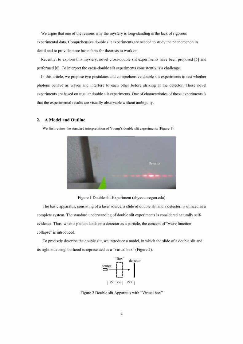
We first review the standard interpretation of Young’s double slit experiments (Figure 1).
Figure 1 Double slit-Experiment (abyss.uoregon.edu)
The basic apparatus, consisting of a laser source, a slide of double slit and a detector, is utilized as a
complete system. The standard understanding of double slit experiments is considered naturally self-
evidence. Thus, when a photon lands on a detector as a particle, the concept of “wave function
collapse” is introduced.
To precisely describe the double slit, we introduce a model, in which the slide of a double slit and
its right-side neighborhood is represented as a “virtual box” (Figure 2).
Figure 2 Double slit Apparatus with “Virtual box”

3
Let us divide the model into 3 zones: zone-1 (Z-1) is from the source to the left side of the virtual
box, the virtual box is zone-2 (Z-2), and zone-3 (Z-3) is from the right side of the virtual box to the
detector. In this article, we study how photons behave in zone-1 and zone-3, and estimate the range of
the right-side boundary of the virtual box.
Figure 3 Schematic of Outline
We start from the wave interpretation of the double slit experiments, and design experiments to test
it. Thus, the schematic drawings in Figure 3 show that light behaves as waves in the entire experiment.
To test whether photons behave as waves in zone-3, we insert: (1) longitudinal “wave shield(s)”
(Figure 3a), denoted as shield; (2) transverse “wave blocker(s)” (Figure 3b), denoted as blocker; (3)
combination of shield and blocker (Figure 3c); all near detectors. We want to observe whether the
interference pattern would be disturbed under the situations shown in Figure 3. To test the right-side
boundary of the virtual box, shield-1 is inserted gradually closer to the double slit (Figure 3d) to
determine where photons would start to change behavior if they do change. Note that at this point, we
assume that photons propagate as waves.
In the rest of the article, we discover that photons behave as particles in zone-1 and zone-3.
3. Double slit Changing Photons’ Behavior 3.1. Two postulates
We propose two postulates related to double slit experiments and then test them.
Postulate-1: in zone-1, photons behave as particles.
Postulate-2: in zone-3, photons behave as particles.

4
One of the consequences of postulate-2 is that in zone-3, each fringe is formed independently and
can be formed partially. Indeed, the experiments testing the consequence strongly support postulate-2.
First, let’s experimentally confirm a rule.
Rule: The particle nature of a single input beam of photons is not changed by a beam splitter (BS),
either reflected by the BS or passing through the BS.
Example-1: when a beam of photons outputted from a BS behaves as particles, then the input beam
of photons behaves as particles, while the other output beam of photons behaves as particles.
Note that in this article, we do not discuss the situation of two input coherent beams; for example,
two beams are inputted into an output beam splitter in a Mach-Zehnder interferometer.
Although the Rule seems trivial, it is utilized to prove postulate-1.
Let’s test the Rule experimentally.
Experiment-1: Testing the Rule.
Experimental Setup (Figure 4a): photons reflected by both BS1 and M1 land on detector-1 (D1),
while photons passing though BS1 land on D2.
Figure 4 Testing Rule (1)
Observation (Figure 4b): D1 and D2 show the images of the source, which indicate that photons
detected on both D1 and D2 have the same particle nature.
The Rule is proved.
3.2 Photons Behaving as Particle before Arriving at Double slit
Now let’s test postulate-1 experimentally.
Experiment-2: Testing postulate-1 in two experimental setups.
Experimental setup-1 (Figure 5a): Photons passing through both BS1 and BS2 strike at D2. Photons
reflected by BS1 and M1 and passing through slide-1 strike at D1. Photons reflected by BS2 and M2
and passing through slide-2 strike at D3. All images are shown on the same detector to visually observe
the phenomenon. To show the difference, we use a cross-double slit for slide-1 (Figure 5b) and a
standard double slit for slide-2.

5
Figure 5 Testing Postulate-1 (1)
Observations (Figure 5c): D2 displays the image of the source, i.e., photons passing through BS1
and BS2 behave as particles. Thus, according to the Rule, photons reflected by BS1/M1 and BS2/M2
traveling towards slide-1 and slide-2 behave as particles. Namely, photons behave as particles before
arriving double slit/cross-double slit, although D1 and D3 show interference patterns created by the
cross-double slit and the double slit, respectively.
Postulate-1 is proven.
Now we have two facts:
(A) It is well known that after passing through a double slit/cross-double slit, a photon is always
absorbed at the discrete points of the detector, as individual particle, i.e., the interference pattern
appears via the varying density of these particle hits on the detector; and
(B) We proved that before striking at a double slit/cross-double slit, photons directly from a laser
source behave as particles.
Experimental setup-2 (Figure 6a): Photons passing through both BS1 and slide strike at D2. Photons
reflected by BS1 and M1 strike at D1. We use a cross-double slit for slide (Figure 6b).
Figure 6 Testing Postulate-1 (2)
Observation (Figure 6c): D1 shows the image of the laser source, which indicates the particle nature.
D2 is an interference pattern created by the cross-double slit.
Conclusions.
(1) D1 shows the particle nature of photons. According to the Rule, reflection by BS1 does not affect
the nature of photons; thus, photons from the source to D1 behave as particles.
(2) According to the Rule, passing through BS1 does not affect the nature of photons; thus, the nature
of photons passing through BS1 towards the slide is the same as that of photons reflected by BS1,

6
i.e., behave as particles. Before striking on the slide of cross-double slit, photons behave as
particles.
Thus, the source emits photons as particles, but as waves. The standard interpretation of double slit
experiments is challenged.
Postulate-1 is proven, i.e., before passing through a double slit/cross-double slit, photons behave as
particles.
3.3. Photons Behaving as Particle before Landing on Detector
Now let’s test postulate-2 experimentally. Note schematic drawings below are not to scale.
3.3.1. Testing Postulate-2 with Longitudinal Shields
Experiment-3: Testing Postulate-2
Experimental Apparatus: Inserting a “shield” (green colored) made of carboard into the apparatus of
the regular double slit experiments between the double slit and detector. The purpose is to test whether
the shield would prevent photons from interfering if photons would behave as waves in Z-3. For
simplicity, shield-1’s orientation is from the center of the double slit points to the center of the zeroth-
order-fringe. We refer shield-1 as longitudinal. Shield-1 is 28 inches long, 1.5 inch wide, and 0.3 mm
thick. The distance between the double slit and the detector is 200 inches. Shield-1 is assumed to
separate waves and thus prevent waves from interfering. An analogy is a breakwater that break water
waves.
Note since we will prove that photons behave as particles in Z-3, in the following schematic
drawings, we will not draw waves, as we did in Figure 3.
Experimental setup-1 (Figure 7a): Shield-1 attaches a detector.
Figure 7 Testing Postulate-2 with Single Shield
Observation (Figure 7b): Shield-1 does not affect the interference pattern at all, which would not be
expected if photons behave as waves.
Experimental setup-2 (Figure 8a): Shield-1 is one inch away from the detector.

7
Figure 8 Testing Postulate-2 with Single Shield
Observation (Figure 8b): (1) Shield-1 does not affect the interference pattern at all; (2) there is the
projection of shield-1 at the middle of the zeroth-order fringe, which would be expected if photons
behave as particles.
Experiment-4: Testing Postulate-2
Experimental apparatus: In addition to shield-1, shield-2 is inserted into the regular double slit
experiments. Two shields form a narrow channel. The purpose is to test whether the channel would
prevent photons from interfering if photons would behave as waves in Z-3. Shield-2 is along the line
between the center of the double slit and the center of the first-order fringe and is 28 inches long, 1.5
inch wide, and 0.3 mm thick.
The experiment is carried out in four setups.
Experimental setup-1 (Figure 9a): Both shield-1 and shield-2 contact the detector.
Figure 9 Testing Postulate-2 with Two Shields
Observation (Figure 9b): We observe the interference pattern, which is exactly the same as that there
were no shield-1 and shield-2. The existence of two approximately parallel shields of 28 inches long
has no effect on the “interference” pattern of 650 nm light at all, which indicates that photons do not
behave as waves, at least within 28 inches of the detector. Otherwise, light waves should be prevented
from interfering with each other, and the “interference” pattern should be disturbed, especially the
zeroth-order and first-order fringes.
Experimental setup-2 (Figure 10a): Moving both shield-1 and Shield-2 back one inch from the detector.

8
Figure 10 Testing Postulate-2 with Two Shields
Observation (Figure 10b): the interference pattern has no change. The projection of shield-1 appears at
the middle of the zeroth-order fringe, while the projection of shield-2 appears at the middle of the first-
order fringe. Only photons behaving as particles can pass through the narrow channel, strike at the
positions of the zeroth-order fringe and first-order fringe on the detector, and form two projections,
while not disturbing the existing interference pattern.
Experimental setup-3 (Figure 11a): whole setup of two shields of 28 inches long attached to the
detector: the zeroth-order fringe is shown between shield-1 and shield-2 on the detector.
(a)
(b)
Figure 11 Testing Postulate-2 with Two Shields
Observation: the interference pattern is the same as if there were no shield-1 and shield-2.
Experimental setup-4 (Figure 12): Two shields 70 inches long attached to the detector, which formed
a long narrow channel. Note that the picture was shot from the “Entrance” to the detector so that the
interference pattern shows and thus, Entrance looks wider.

9
Figure 12 Testing Postulate-2 with Two Shields 70 inches long
Observation: the interference pattern is the same as if there were no shield-1 and shield-2. The
existence of two long shields has no effect on the interference pattern, which would be expected only if
photons behave as particles.
Experimental setup-5 (Figure 13a): Shield-2 is placed at 60 inches from the double slit; shield-1 stays
at the same position as in Figure 8a.
Figure 13 Testing Postulate-2 with Two Shields
Observation (Figure 13b): The interference pattern has no change. The projection of shield-2 is wider
than that of shield-1, since it is closer to the double slit.
Comprehensive double slit experiments have been carried out: at positions of different distances
from the detector, for example, 40 inches, 80 inches, and 120 inches. We always observe the same
interference pattern and projections of shield-1 and shield-2.
Conclusion: Only particles can pass through the long and narrow channel between shield-1 and shield-
2, and form fringes on the detector; thus, photons behave as particles long before landing on the
detector.
Postulate-2 is proved experimentally.
In contrast, photons are distributed with a wave-like interference pattern on the detector.
This is a paradox.
We discuss this paradox later and provide an interpretation.
3.3.2 Testing Postulate-2 with Transverse Blockers.
Experiment-5: Testing Postulate-2

10
Let’s consider five experimental setups.
Experimental Setup-1 (Figure 14a): blocker-10, blocker-11 and blocker-12, each 0.5-inch wide, are
placed along the normal vector of the detector, and separated by 4 inches.
Figure 14 Fringes Formed Independently
Observation (Figure 14b): Three blockers are arranged such that the zeroth-order fringe and two first-
order fringes are formed on blocker-10, blocker-11 and blocker-12. The existence of each blocker does
not affect the fringes formed on other blockers and the detector. Namely, fringes are formed
independently.
Experimental Setup-2 (Figure 15a): blocker-11 and blocker-12 are placed along the normal vector of
the surface of the detector and separated by 4 inches.
Figure 15 Fringes Formed Independently and Partially
Observation (Figure 15b): Two blockers are arranged such that portions of the zeroth-order fringe are
formed on the detector, blocker-11 and blocker-12 respectively. Thus, the fringe can be formed
partially. The existence of each blocker does not affect the fringes formed on other blockers and
detector. Namely, fringes are formed independently.

11
Experimental Setup-3 (Figure 16): blocker-11 and blocker-12 are placed along the normal vector of
the surface of the detector.
Figure 16 Fringes Formed Independently
Observation: The zeroth-order fringe, m = +1 fringe and m = -1 fringe are formed on the detector,
blocker-11 and blocker-12 respectively.
Experimental Setup-4 (Figure 17): blocker-11 and blocker-12 are placed along the normal vector of
the surface of the detector, and separated by 4 inches.
Figure 17 Fringes Formed Independently and partially
Observation (Figure 17): Portions of the zeroth-order-fringe are formed on blocker-11 and blocker-12
respectively, which indicates that the fringe can be partially formed. The m = +1 fringe and m = -1
fringe are formed on blocker-11 and blocker-12 respectively, i.e., formed independently.

12
Experimental Setup-5 (Figure 18): blocker-11 and blocker-12 are placed along the normal vector of
the surface of the detector, and separated by 4 inches.
Figure 18 Fringes Formed Independently and partially
Observation (Figure 18): Portions of the zeroth-order fringe are formed on detector and blocker-11
respectively, which indicates that the fringe can be formed partially. The m = +1 fringe and m = -1
fringe are formed on blocker-11 and blocker-12, respectively, i.e., formed independently.
Conclusion: Fringes are formed independently and partially, which would be expected only if
photons behave as particles in Z-3. Postulate-2 is proved.
In contrast, photons are distributed with a wave-like interference pattern on the detector.
This is a paradox.
We discuss this paradox later and provide an interpretation.
3.3.3. Testing Postulate-2 with Combinations of Longitudinal Shields and Transverse Blocker.
We have shown that, on the one hand, longitudinal shield-1 and shield-2 do not disturb the
interference pattern in zone-3 at all. On the other hand, blockers do block the propagation of photons as
photons are particles. Now let’s test what are the effects of combinations of shields and blockers.
Experiment-6: Testing Postulation-2

13
Now let us place blocker-1 at the other end of shield-1 and shield-2, where we denote it as Entrance,
i.e., photons enter the narrow channel between shield-1 and shield-2 from there (Figure 19a). The
interference pattern is formed on blocker-1 instead of the detector (Figure 19b).
Figure 19 Shields and Blocker We perform this experiment in two setups.
Experimental Setup-1 (Figure 20a): Cutting the top portion of blocker-1.
Figure 20 Cut Top Half of Blocker-1 and Pattern Observation (Figure 20b): the bottom half of the fringes are still on blocker-1, while the top half are
on the detector. Namely fringes can be formed partially. And shields have no effect at all.
Experimental Setup-2 (Figure 21a and Figure 21b): cut a “U” shape gap at the position of the zeroth-
order fringe on blocker-3.

14
Figure 21 Blocker-3 with Cut Observation (Figure 21c): Photons pass through the cut and form the exactly same shape of patterns
on the detector, which shows the particle nature of light and indicates that photons move along straight
lines.
Experiment-7: Testing Postulate-2.
We perform this experiment in two setups.
Experiment Setup-1 (Figure 22a): insert transverse blocker-2 one inch wide into the channel formed
by shield-1 and shield-2.

15
Figure 22 Blocker-2 in Channel
Observation (Figure 22b): Two fringes are formed on blocker-2, and the remaining fringes are formed
on the detector. Namely, Fringes can be formed independently. Two shields have no effect at all. This
observation indicates that photons behave as particles.
Experimental Setup-2 (Figure 23): cut triangles on blocker-2 at the locations of the zeroth-order
fringe and the first-order fringe. Then insert blocker-2 into the channel.
Figure 23 Blocker-2 with Two Cuts
Observation (Figure 23): Photons pass through two triangle-shaped cuts and form exactly the same
triangle-shaped patterns on the detector, which shows the particle nature of photons and shows that
photons move along straight lines. Note that photons are not directly from the source; they are just pass
through a double slit. If photons would behave as waves, this phenomenon would not be explained.
In contrast, photons are distributed with a wave-like interference pattern on the detector.
This is a paradox. We discuss this paradox later and provide an interpretation.

16
3.3.4. Testing Postulate-2 with 2D-cross-double slit
The 1D-double slit apparatus/experiments have been extended to 2D-cross-double slit
apparatuses/experiments [5-6], which have more varieties (Appendix). Without losing generality, we
perform comprehensive double slit experiments with cross-double slit.
Experiment-8: Testing Postulate-2
Experimental Setup-1 (Figure 24): Shield-1 and shield-2 attach detector and form a narrow channel.
Figure 24 2D-pattern vs. Channel
Observation: The channel does not disturb the interference pattern at all.
Experimental setup-2 (Figure 25a): using blocker-3 to block the bottom portion of the 2D interference
pattern.
Figure 25 Testing Postulate-2 with Cross-double slit
Observation (Figure 25): the top portion of the 2D interference pattern is shown on the detector
(Figure 25b), while the bottom portion is shows on blocker-3. Namely, 2D patterns are created
independently and partially. Only particle can do that.
Postulate-2 is proved experimentally: in zone-3, photons move along predetermined trajectories that
are straight lines and behave as particles.

17
3.3.5. Testing Range of Virtual box
Experiment-9: searching the range of the Virtual box.
Experimental Setup (Figure 26a): Moving a shield towards the double slit and observing. In this
article, the shield is stopped at a position 2.5 cm from the double slit.
Figure 26 Testing Range of Virtual box (Unit: cm)
Observation (Figure 26b): both the “interference” pattern and the projection of the shield are show on
the detector. The latter is much wider. Thus, the width of zone-3 is at least 497.5 cm, in which photons
behave as particles.
Now let’s calculate the width of the projection of the shield on the detector. The regular equation holds,
𝑦𝑦 = 𝜆𝜆𝜆𝜆𝑑𝑑𝑚𝑚. (1)
For our experiment, the wavelength is 650 nm, the distance from the double slit to one end of the
carboard is 2.5 cm, the spacing between two slits is 0.25mm, and the cross-section, thickness, of the
carboard is 0.3 mm. Substituting into Eq. (1), we obtain 𝑚𝑚 ≈ 4.6, namely up to the 4th bright fringes
are all blocked by the cross section of the shield.
4. Discussion
On the one hand, in the double slit experiments, it is interpreted that the light behaves as a wave
and creates an interference pattern on a detector, which would not be expected if light behaves as
particle. Indeed, the interference patterns do exist in the comprehensive double slit experiments.
On the other hand, we have discovered experimentally novel phenomena that, in zone-3 of the
double slit apparatuses, photons indeed behave as particles, which would not be expected if light
behaves as waves.
This seems a paradox.
We suggest an interpretation to address this paradox. A laser source emits photons as a beam of
particles (as proved experimentally when testing postulate-1). Those photons travel into the virtual box.
In the language of “wave”, the function of the “virtual box” is a process of “forming” the distribution

18
of photons as waves inside the “virtual box”. In the language of “particle”, the function of the “Virtual
box” is a process of “grouping” photons into different groups/streams, denoted the process as
“grouping”, which correspond to different fringes respectively. Photons landing on the same fringe are
defined as “in the same group”. In practice, a “group” of photons propagates as a stream of particles
and arrives at the same fringe continuously. Therefore different groups/streams corresponding to
different fringes are formed inside the virtual box. Where the process completed, either in “wave
language” or in “particle language”, is defined as the right-side boundary of the virtual box. When
coming out of the “virtual box”, photons behave as groups/streams of particles (as proved
experimentally when testing postulate-2), and follow the trajectories that lead to the different fringes.
Although the trajectory of each photon cannot be determined, the trajectory of each group/stream of
photons is determined while they are inside the “virtual box”. The trajectory of each group/stream of
photons is shown by the evolution of each fringe after photons coming out the “virtual box”. However,
the trajectories cannot be directly observed at the right-side boundary of the “Virtual box”, because
existing observation equipment can only register photons, but cannot detect the directions of each
photon. At the right-side boundary, different groups/streams of photons are mixed together, but they
have their own moving directions. One can observe the patterns only when different groups/streams of
photons separate. The mechanism of “forming” or “grouping” is mystery.
Based on comprehensive double slit experiments, we suggest that (1) the above experiments
indicate that the “particle nature” of photons is intrinsic and (2) restudy the mystery of double slit
experiments, complementarity principle and wave-particle duality.
5. Conclusion
We propose and perform comprehensive double slit/cross-double slit experiments with simple
apparatuses to study the basic quantum mystery. Novel phenomena are discovered, which are naked-
eye-visible.
Based on three facts discovered from above experiments, (1) shields have no “wave shielding
effect” on fringes, i.e., there is no wave in Z-3; (2) each fringe is formed independently; (3) each fringe
can be formed partially, we conclude that, before arriving at a slide of double slit/cross-double slit and
before landing on the detector/screen, i.e., in zone-1 and zone-3, photons behave as particles.
Now, we have more complex and comprehensive experimental data, which suggest a criterion on
interpretations of the phenomena.

19
Appendix: Cross-double slit Let us review cross-double slit apparatuses that are used in comprehensive double slit experiments.
Figure A1 Double slit vs. Cross-Double slit
Figure A1 compares a slide of standard double slit with a slide of cross-double slit.
Next show a standard double slit/interference pattern and some of cross-double slit/interference
patterns without detail discussion.
Figure A2 One double slit and interference pattern
Figure A3 Two double slits and pattern. Figure A4 Two double slits and pattern
Figure A5 Three double slits and pattern. Figure A6 Three double slits and pattern
Figure A7 Three double slits and pattern. Figure A8 Four double slits and pattern

20
Figure A9 Five double slits and pattern. Figure A10 Six double slits and pattern
There are many more varieties of cross-double slit apparatuses, either with different numbers of
double slits crossing together, or crossing at different angles, etc. Mathematically interpreting
observations consistently is a challenge. The cross-double slit experiments are more mysterious than
the standard double slit experiments.
References [1] de Broglie, Louis, 1928, “La nouvelle dynamique des quanta”, in Solvay, pp. 105–132, 1928.
[2] Bohm, David, “A Suggested Interpretation of the Quantum Theory in Terms of ‘Hidden’ Variables, I and II”, Physical
Review, 85(2): 166–193. doi:10.1103/PhysRev.85.166, 1952.
[3] R. Feynman, R. Leighton, and M. Sands “The Feynman Lectures on Physics” (Addison-Wesley, Reading), Vol. 3, 1965.
[4] S.A. Rashkovskiy, “Is a rational explanation of wave-particle duality possible?”, arXiv: 1302.6159v1 [quant-ph], 2013.
[5] Hui Peng, “Cross-Double slit Experiment and Extended-Mach-Zehnder Interferometer”, open-science-
repository.com/physics-45011872.html (2019).
[6] Hui Peng, “Observations of Cross-Double slit Experiments”, Inter. J. of Phys. 8(2), 39-41, 2020.


![[XLS]ncseducation.comncseducation.com/Result-on-Website.xls · Web viewMordijiush J. Sangma SLIT-2247 Akash Boro SLIT-2248 Anisha Das SLIT-2249 Udit Narayan Roy SLIT-2250 Michael](https://static.fdocuments.us/doc/165x107/5ab167d47f8b9a6b468c7b61/xls-viewmordijiush-j-sangma-slit-2247-akash-boro-slit-2248-anisha-das-slit-2249.jpg)