
Tensile Strength Properties of Rice Husk-Rice Husk Ash Filled ...
University of ConnecticutOpenCommons@UConn
Master's Theses University of Connecticut Graduate School
12-15-2016
Comprehensive Applications of Rice HuskBiomassZichao WeiUniversity of Connecticut,Storrs, [email protected]
This work is brought to you for free and open access by the University of Connecticut Graduate School at OpenCommons@UConn. It has beenaccepted for inclusion in Master's Theses by an authorized administrator of OpenCommons@UConn. For more information, please [email protected].
Recommended CitationWei, Zichao, "Comprehensive Applications of Rice Husk Biomass" (2016). Master's Theses. 1033.https://opencommons.uconn.edu/gs_theses/1033
i
Comprehensive Applications of Rice Husk Biomass
Zichao Wei
B.E., Shenyang University of Chemical Technology, 2014
A Thesis
Submitted in Partial Fulfillment of the
Requirements for the Degree of
Master of Science
At the
University of Connecticut
2016

ii
Copyright by
Zichao Wei
2016
iii
APPROVAL PAGE
Master of Science Thesis
Comprehensive Applications of Rice Husk Biomass
Presented by
Zichao Wei, B.E.
Major Advisor________________________________________________________________
Dr. Luyi Sun
Associate Advisor_______________________________________________________________
Dr. Richard Parnas
Associate Advisor_______________________________________________________________
Dr. Jie He
University of Connecticut
2016

iv
Acknowledgements
I would like to thank my major advisor Dr. Luyi Sun for his guidance and support through
my whole master degree’s study. I appreciate his patient, comments, contribution of time and
precisely academic attitude. His encouragement and advices are the cornerstones to make me
complete this decent work. He also provided many advices, suggestions and experience for my
career and personal life to give me enormous help. I am honored to have such a good and wisdom
mentor.
I also want to express my gratitude to my committee members, Dr. Richard Parnas and Dr.
Jie He for their valuable time, supports and precious comments for my master thesis and defense.
I’m grateful to Dr. Zhaofeng Wang, the former postdoctoral lab mates for his guidance on
my research experience. He is a good teacher and helpful friend. I also would like to thank all the
group members and all my friends in University of Connecticut. It’s my pleasure and glad to meet
with you. At the same time, I specially want to thank the undergraduate students, Mr. William R.
Tait and Ms. Alice Hu for their assistance on my research and defense.
Mostly, I would like to thank my parents, Zeguo Wei and Xiaochun Jiang for their endless
love, encouragement and support.

v
Table of Contents
Chapter 1. Introduction: Comprehensive Applications of Rice Husks ................................... 1
1.1 Introduction .................................................................................................................... 1
1.2 Chemical Production........................................................................................................ 1
1.2.1 Active carbon ................................................................................................................ 2
1.2.2 Fibers ........................................................................................................................ 3
1.2.3 Fossil Fuel Alternatives ........................................................................................... 5
1.3 Construction Materials .................................................................................................. 8
1.4 Composite Materials .................................................................................................... 10
1.5 Sorption of RH applications ........................................................................................ 11
1.6 Power Generation ......................................................................................................... 12
1.7 Comprehensive Utilization of RHs ............................................................................. 13
1.8 Conclusion ..................................................................................................................... 14
Chapter 2. Synthesis of Green Phosphor from Highly Active Amorphous Silica Derived
from Rice Husks .......................................................................................................................... 21
2.1 Introduction .................................................................................................................. 21
2.2 Experiment .................................................................................................................... 22
2.2.1 Preparation of silica from RHs ............................................................................... 22
2.2.2 Preparation of Zn2SiO4:Mn2+ ................................................................................. 23
2.2.3 Characterization ..................................................................................................... 23
2.3 Results and Discussion ................................................................................................. 24
2.4 Conclusion ..................................................................................................................... 38
vi
Chapter 3. Self-Assembled Multifunctional Lignocellulose Aerogel and Silica Nanoparticles
from Rice Husks: a Comprehensive Utilization Strategy ....................................................... 42
3.1 Introduction .................................................................................................................. 42
3.2 Experimental................................................................................................................. 43
3.2.1 Materials ................................................................................................................. 43
3.2.2 Preparation of LC aerogel ...................................................................................... 44
3.2.3 Hydrophobic modification of RH LC aerogel ......................................................... 45
3.2.4 Preparation of carbon aerogels .............................................................................. 45
3.2.5 Preparation of RH silica nanoparticles .................................................................. 45
3.2.6 Characterization ..................................................................................................... 46
3.3 Results & Discussion .................................................................................................... 46
3.3.1 Formation of LC aerogel from RHs ........................................................................ 46
3.3.2 Formation of carbon aerogel .................................................................................. 49
3.3.3 Porosity properties and surface areas of the LC aerogel and carbon aerogels ..... 51
3.3.4 Hydrophobicity and Oil Spill Applications ............................................................. 52
3.3.5 Silica nanoparticles from IL-RH residue ................................................................ 54
3.4 Conclusion ..................................................................................................................... 55
Chapter 4. Summary and Outlook ............................................................................................ 59
4.1 Summary ....................................................................................................................... 59
4.2 Outlook .......................................................................................................................... 60

vii
List of Figures
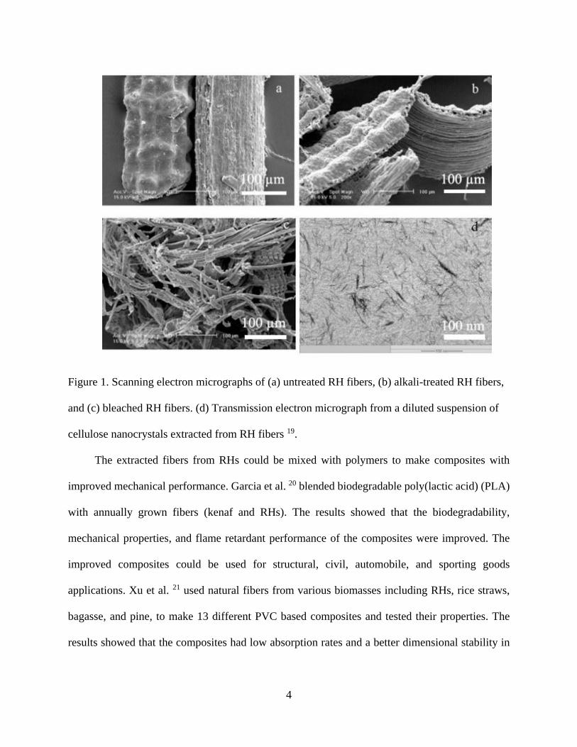
Figure 1. Scanning electron micrographs of (a) untreated RH fibers, (b) alkali-treated RH fibers,
and (c) bleached RH fibers. (d) Transmission electron micrograph from a diluted
suspension of cellulose nanocrystals extracted from RH fibers. .................................... 4
Figure 2. A representative fluidized-bed reactor fast pyrolysis system. ......................................... 7
Figure 3. Sinter method for the preparation of lightweight bricks. .............................................. 10
Figure 4. Technological process of comprehensively utilizing RHs. ........................................... 14
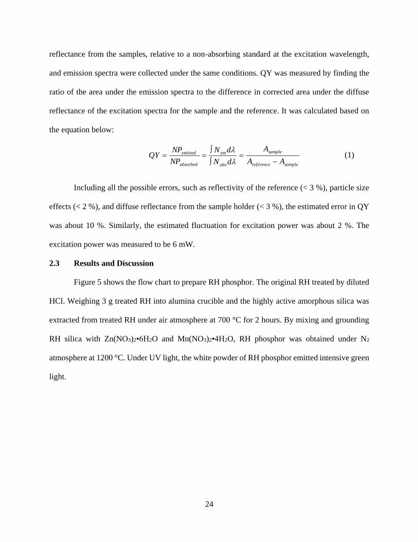
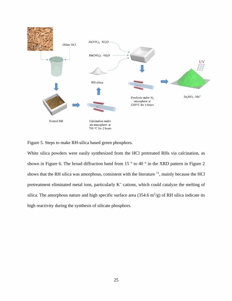
Figure 5. Steps to make RH-silica based green phosphors. .......................................................... 25
Figure 6. X-ray diffraction of the synthesized RH silica. The inset figure (a) is a digital picture of
the sample; figure (b) is SEM of RH-silica nanoparticles ............................................ 26
Figure 7. X-ray diffraction patterns of Zn2SiO4:0.08Mn2+ phosphors synthesized at temperatures
of 1000, 1100, and 1200 °C under N2 atmosphere for 4 hours. .................................... 28
Figure 8. Appears of the RH phosphor samples prepared at different temperatures: 1000 °C (A and
D), 1100 °C (B and E), and 1200 °C (C and F) under visible light (A-C) and 256 nm UV
light (D-F). Scale bars represent 1 cm. ......................................................................... 29
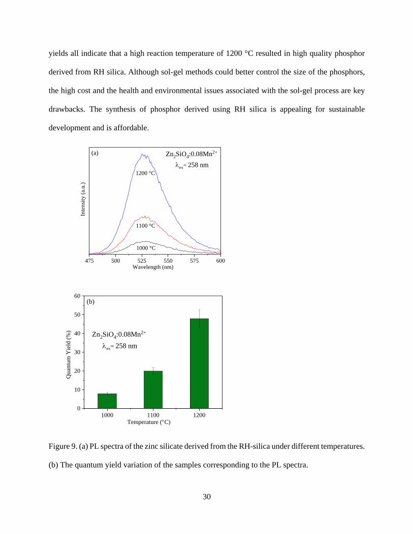
Figure 9. (a) PL spectra of the zinc silicate derived from the RH-silica under different temperatures.
(b) The quantum yield variation of the samples corresponding to the PL spectra. ...... 30
Figure 10. Powder X-ray diffraction patterns of the Zn2SiO4:Mn2+ phosphors combustion-
synthesized under different doping concentrations under 1200°C for 4h. ................... 32
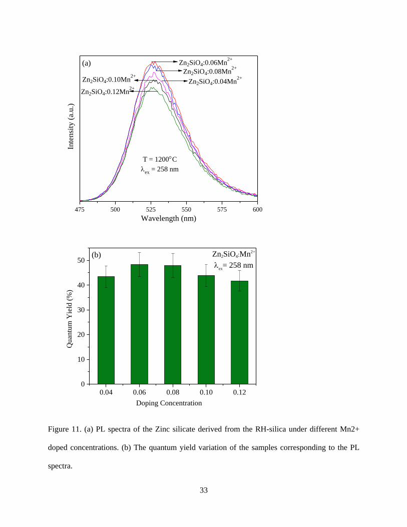
Figure 11. (a) PL spectra of the Zinc silicate derived from the RH-silica under different Mn2+
doped concentrations. (b) The quantum yield variation of the samples corresponding to
the PL spectra. .............................................................................................................. 33

viii
Figure 12. Decay curve of the green emission at 527 nm under 258 excitation from the
Zn2SiO4:0.06Mn2+ phosphor. ........................................................................................ 35
Figure 13. (a) PL spectra of the zinc silicate derived from the RH-silica, commercially-used silica,
and silicic acid. (b) The quantum yield variation of the sample corresponding to the PL
spectra. .......................................................................................................................... 37
Figure 14. Flow chart of the process to prepare LC aerogel, carbon aerogel, and RH silica. ...... 47
Figure 15. Digital picture of a lignocellulose aerogel on a dandelion. ......................................... 48
Figure 16. SEM images of the LC aerogel synthesized after 5 cycles of NFT. ............................ 49
Figure 17. SEM images of the carbon aerogel prepared via the pyrolysis of LC aerogel under
1000 °C for 2 hours. ..................................................................................................... 49
Figure 18. XRD patterns of the LC aerogel and the cellulose derived from RHs ........................ 51
Figure 19. N2 adsorption-desorption isotherms of the LC aerogel and carbon aerogel. ............... 52
Figure 20. Water contact angle of the MTMS treated LC aerogel: (a) on an external surface, and
(b) on a freshly cut surface. ........................................................................................ 53
Figure 21. Pump oil absorption process by treated LC aerogel. ................................................... 54
Figure 22. XRD patterns of the silica samples derived from IL-RH and HCl treated raw RHs. .. 55

ix
List of Tables
Table 1. Gas composition I gasifier by random sampling. ............................................................. 6
Table 2. Composition of bio-oil from RHs. .................................................................................... 7
Table 3. Surface area of the LC aerogel and carbon aerogel. ....................................................... 52

x
Comprehensive Applications of Rice Husk Biomass
Zichao Wei, M.S.
University of Connecticut, 2016
Rice husks (RHs) have recently attracted high attention due to their potential for many
applications, including construction materials, composite materials, adsorption materials, chemical
production, and power generation. RHs are an appealing alternative because of their low cost and
high silica content. So far, most researchers mainly focus on the utilization of one component (such
as silica) while ignoring others. Comprehensive utilization of RH biomass and diversified products
are the key goals for this research field.
In this thesis, the two main components of RHs, silica and lignocellulose, were extracted
from RH biomass. The high tempered calcination served as the extraction process of the highly
reactive RH silica nanoparticles. Because of its remarkable physiochemical properties, green
phosphor of Zn2SiO4:Mn2+ was synthesized under a high temperature pyrolysis method. This study
also investigated the effects of reaction temperature and Mn2+ doping concentration on the
photoluminescence properties of the RH silica phosphor. By comparing with the phosphor
prepared from commercially used silica, RH silica phosphor showed superior photoluminescence
properties. Because RHs are an inexpensive resource and the RH silica phosphor exhibited better
performance, it should be considered a promising alternative.
The second part of the thesis studied the extraction of the lignocellulose from RH biomass
by using ionic liquid (BMIMCl). Through liquid nitrogen frozen and thaw (NFT) process, water
regeneration, and CO2 supercritical drying, the light and porous lignocellulose aerogel was
prepared. In addition, the lignocellulose aerogel can be further converted to a carbon aerogel via a
facile pyrolysis process. Because of the inherited porous structure, the carbon aerogel is expected

xi
to find wide applications in many areas. Silane agent (MTMS) modification of the lignocellulose
aerogel is another route to expand its applications. The treated lignocellulose aerogel exhibited to
be highly hydrophobic, making it effective in oil spill adsorption. Based on the comprehensive
utilization strategy, the RH residue separated from IL solution was used to prepare highly active
and amorphous silica nanoparticles, which also have widespread application.

1
Chapter 1. Introduction: Comprehensive Applications of Rice Husks
1.1 Introduction
Rice is one of the most common food crops in the world. Additionally, it is one of the largest
sources of biomass, namely, rice husks (RHs). In the past, RHs were considered as a waste.
Farmers disposed of RHs by open-field burning, which generated significant pollution, especially
in developing countries 1. Researchers have found that RHs contain silica (15-28 wt. %) and
lignocellulose (LC, 72-85 wt. %), which can be further categorized into cellulose (35-40 wt. %),
hemicellulose (15-20 wt. %), and lignin (20-25 wt. %). The exact weight percentages of these
components are determined by the water quality, environment, climate, and soil conditions of
where the rice is grown 2. Because of the high concentration of lignocellulose and silica in RHs,
RH biomass can be applied for a wide variety of areas, including chemical production, construction
materials, agriculture, adsorption materials, and power generation. In these applications, RH
biomass exhibits two major advantages: low cost and sufficiently good quality. Considering RHs
contains both inorganic silica and organic lignocellulose, it is highly desirable to derive both
components for practical applications. In this way, RHs can serve as a sustainable and cost-
effective resource for various industries.
1.2 Chemical Production
Lignocellulose and silica are the main contents in RHs. They can be used as alternative
resources in the production of chemical products, such as active carbon (AC), fibers, and syngas.
RHs can also be used in the production of biofuel. The low price and massive quantity of RHs
make them an attractive resource compared to other biomasses.

2
1.2.1 Active carbon
Active carbon (AC) is a known adsorbent that exhibits a high adsorption capacity and large
surface area 3. It has been widely used as a catalyst support 4, gas storage material 5 and adsorbent
material 6. Many biomasses can serve as the precursor of AC, including sunflower shells 7, corn
straws 8, olive stones 9, cotton residues 7, etc. RHs biomass can also play an important role in AC
production because of its high organic content and low price. The physical activation method and
chemical activation method can be used to transfer RH biomass to AC.
For the physical method, the carbonization process will be completed under nitrogen or
inert gas atmosphere at a temperature range of 600-900 °C. Activation will occur at high
temperatures, 600-1000 °C, when the sample is exposed to an atmosphere of steam, carbon dioxide,
or the combination of the two gases. For the chemical method, impregnation of RHs is assisted by
alkaline, alkali carbonates, acids, or metal salts. Then the sample is activated with N2 at
temperature of 400-900 °C.
Applications of AC are widespread. Zhu et al. 10 explored the physical activation method
to make AC from RHs. Their results showed that the prepared AC can effectively remove NH4+
ions, and there was an increased ion removal with an increased dosage. Yao et al. 11 recently used
microwave-assisted nitric acid oxidation to modify the AC from RHs. They found that the
modified AC exhibited a fast adsorption of Pb (II) than the un-modified one. Mashhadi et al. 12
used a similar modification method by using sulfuric acid to make AC for the removal of Hg (II).
Besides as an adsorbent, RH derived AC could also be applied for catalyst support 13 and hydrogen
storage 14 because of its high meso-porosity and surface area.

3
1.2.2 Fibers
Because of the high content of lignocellulose (including cellulose, hemicellulose and lignin),
RHs can be used to prepare natural fibers. Natural cellulose fibers can be extracted from
lignocellulose by using bacterial, fungal, mechanical, or chemical methods 15. Cellulose fibers
from RHs could be extracted by bacteria and fungi, an environmentally friendly and energy-saving
process yet time-consuming. The more common process of extraction is the chemical method.
Sodium hydroxide, sulfuric acid, and oxalic acid are the typical chemicals used to remove the
components other than cellulose from RHs. As shown in Figure 1a and 1b, the alkali treatment
made the smooth surface of RH fibers rougher, which suggests that alkali could remove some
impurities from the cellulose components. Figure 1c shows that the acetic bleaching process
separated RH fiber bundles into individual fibers. Figure 1d shows that the acid hydrolysis
treatment cleaved the amorphous region of cellulosic micro-fibrils transversely, keeping the
straight crystalline domains intact. This allows the cellulose derived from RHs to be used as a
nanomaterial, which could be applied for advanced applications, such as photonic crystalline
materials 16, graphene quantum dots 17, etc. Mechanical methods can also be employed to separate
the cellulose fibers from RHs, such as using decorticating machines, steam explosion, Tilby
process 18.
4
Figure 1. Scanning electron micrographs of (a) untreated RH fibers, (b) alkali-treated RH fibers,
and (c) bleached RH fibers. (d) Transmission electron micrograph from a diluted suspension of
cellulose nanocrystals extracted from RH fibers 19.
The extracted fibers from RHs could be mixed with polymers to make composites with
improved mechanical performance. Garcia et al. 20 blended biodegradable poly(lactic acid) (PLA)
with annually grown fibers (kenaf and RHs). The results showed that the biodegradability,
mechanical properties, and flame retardant performance of the composites were improved. The
improved composites could be used for structural, civil, automobile, and sporting goods
applications. Xu et al. 21 used natural fibers from various biomasses including RHs, rice straws,
bagasse, and pine, to make 13 different PVC based composites and tested their properties. The
results showed that the composites had low absorption rates and a better dimensional stability in

5
water. It suggested that PVC filled with natural fibers had the properties comparable with those of
PVC/wood composites 21.
1.2.3 Fossil Fuel Alternatives
Alternative energy has recently attracted much attention because of the need for clean power
production. Syngas and biofuels should be popular substitute fuel resources, because they are
environmentally friendly and inexpensive. The syngas extracted from RHs has been explored via
gasification. The gas compositions are shown in Table 1 22. Note that H2 and CH4 have potential
as renewable fuels. In the gasification process, there are two types of reactors, fluid bed reactor
and tube reactor 23. The typical temperature is 700 to 1000°C and typical equivalence ratio 0.22-
0.34 24. And the selected catalyst usually dictates the quality of the synthesized syngas. It was
reported that different catalysts influence the syngas compositions. Kuo et al. 25 explored how
different catalysts could affect the reaction. Alkali catalysts promoted the rate of gasification and
increased the hydrogen concentration in the syngas. Nickel based catalysts were also quite
effective for hydrogen generation 26.

6
Table 1. Gas composition I gasifier by random sampling 22.
Temperature (°C) 730
730
750
760
760
790
820
820
830
830
830
Gas Composition
(%)
CO2 15.4 16.2 16.0 15.5 15.3 15.7 14.6 15.3 15.1 14.5 15.3
CO 19.0 18.6 17.4 18.7 15.4 15.9 15.8 16.5 16.5 15.6 16.1
CH4 6.8 7.3 8.0 7.3 8.8 6.8 5.0 6.7 7.5 8.4 4.1
CnHm 1.7 1.6 1.6 1.6 1.5 1.5 1.4 1.3 1.5 1.0 1.2
H2 3.7 1.4 1.6 1.4 0.4 2.3 7.1 3.2 2.5 1.5 7.7
N2 51.7 53.5 54.3 54.3 56.9 56.5 54.5 56.3 55.6 57.5 53.9
O2 1.7 1.4 1.1 1.2 1.7 1.3 1.6 2.0 1.2 1.5 1.6
Gas Heating
Value (MJ N m-3) 6.1 6.1 6.2 6.2 6.1 4.7 5.4 5.7 6.0 5.8 5.1
Bio-fuel is expected to play a significant role in fuel market because of its environmentally
friendly nature and its renewability as opposed to fossil fuels. The extraction of bio-ethanol and
bio-oil from RHs have attracted high interest because of the high lignocellulose content and the
low price of RHs 27, and have achieved a yield of 13.9% and 16.1%, respectively 28.
Generally, the production of bio-ethanol consists of three procedures. Firstly, RHs are treated
with acid. For cellulose, typically a diluted acid pretreatment is adopted, and for hemicellulose, a
concentrated acid pretreatment is preferred. Then an assayed enzyme is mixed with the pretreated
RHs to induce hydrolysis. This is also called the saccharification process, in which the biomass is
changed to monomeric sugars. At last, fermentation is employed to yield ethanol.
Bio-oil is another bio-fuel product, which is made via pyrolysis. The main components of
bio-oil were analyzed by Zheng et al. 27c and listed in Table 2. Two types of reactors are used for
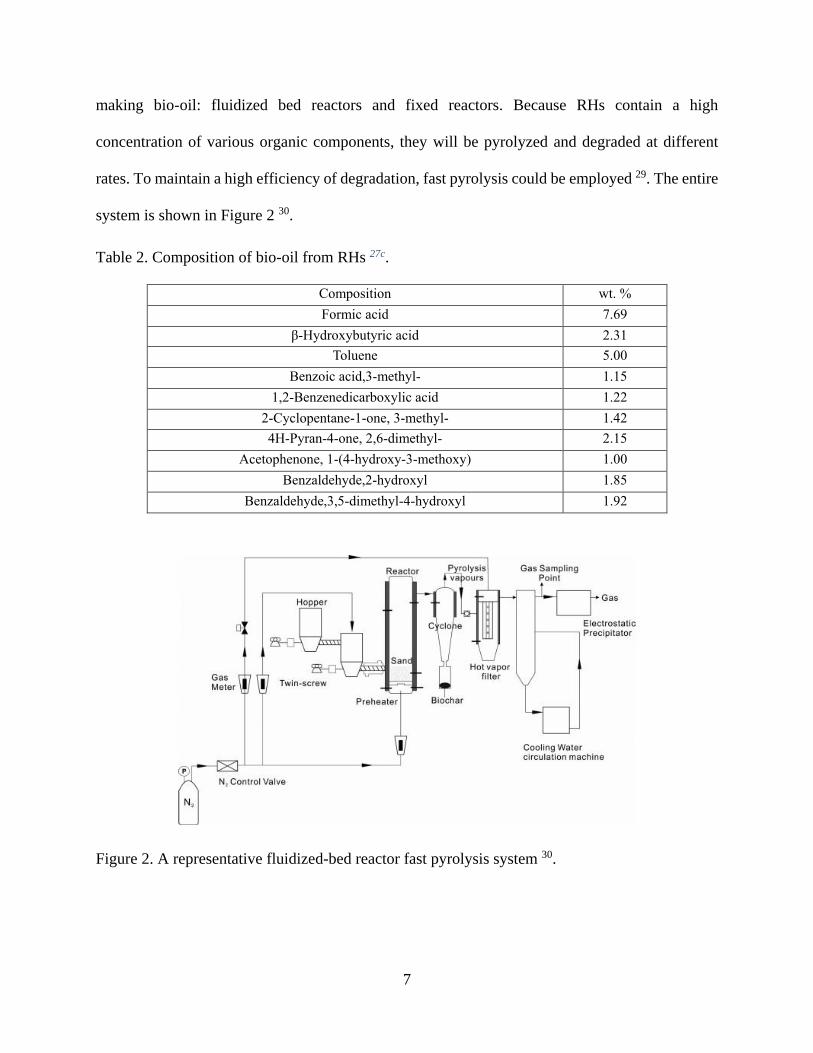
7
making bio-oil: fluidized bed reactors and fixed reactors. Because RHs contain a high
concentration of various organic components, they will be pyrolyzed and degraded at different
rates. To maintain a high efficiency of degradation, fast pyrolysis could be employed 29. The entire
system is shown in Figure 2 30.
Table 2. Composition of bio-oil from RHs 27c.
Composition wt. %
Formic acid 7.69
β-Hydroxybutyric acid 2.31
Toluene 5.00
Benzoic acid,3-methyl- 1.15
1,2-Benzenedicarboxylic acid 1.22
2-Cyclopentane-1-one, 3-methyl- 1.42
4H-Pyran-4-one, 2,6-dimethyl- 2.15
Acetophenone, 1-(4-hydroxy-3-methoxy) 1.00
Benzaldehyde,2-hydroxyl 1.85
Benzaldehyde,3,5-dimethyl-4-hydroxyl 1.92
Figure 2. A representative fluidized-bed reactor fast pyrolysis system 30.

8
1.3 Construction Materials
The manufacture of existing building materials including concrete, particle boards, and
bricks consumes a large amount of natural resources and causes various environmental issues
primarily because of mining and air pollution 31. Recycling bio wastes like RHs as construction
materials is an attractive alternative because of the possible reduction in both energy and raw
materials used 31.
The relatively low density of RHs was utilized by adding RHs to concrete to decrease thermal
conductivity. RHs were added to concrete up to 30 wt. %. The decreased density lowered the
thermal conductivity from ca. 1.54 to 0.71 W/mK. Although the compressive strength of the RHs
filled concreate decreased from 37.5 to 17.6 MPa, the concrete was sufficient for practical
applications 32.
With an increasing demand for wood construction materials, RHs are one of many
agricultural byproducts that are being investigated for the manufacture of particle boards 31.
Particle boards were made from a 30 wt. % RHs and 70 wt. % wood (with urea-formaldehyde and
phenol-formaldehyde resins) 33. However, formaldehyde is expensive and brings health concerns.
It is highly desirable to replace formaldehyde in particle board manufacturing. Soybean protein
concentrate (SPC) was successfully used to bind RHs to form particle boards without the use of
petrochemical derived resins 34. Proteins functioning as adhesives is of interest because they are
one of the most abundant and least expensive biologically derived feedstock 35. Particle boards
was initially prepared by blending RHs with home-made SPC adhesive (10 wt. %). Then the
mixtures were dried at 70°C until 40 % moistures was reached. The balanced mixtures were
pressed into particle board 10 minutes at 140 ºC under a pressure of 2.9 MPa 36. The particles
boards made of H2O2 bleached RHs and SPC exhibited an increased modulus of rupture and
9
modulus of elasticity 36. The RH particle boards satisfy the US standard ANSI/A208.1
requirements for M1, MS, and M2-grade medium-density particleboards 36. Although the particle
boards from RHs do not display the same level of strength as the ones made of wood, they have
unique properties. For example, the particle board made of a mixture of RHs and sawdust exhibited
more effective sound absorbing performance than the commercial gypsum-fiber boards 37.
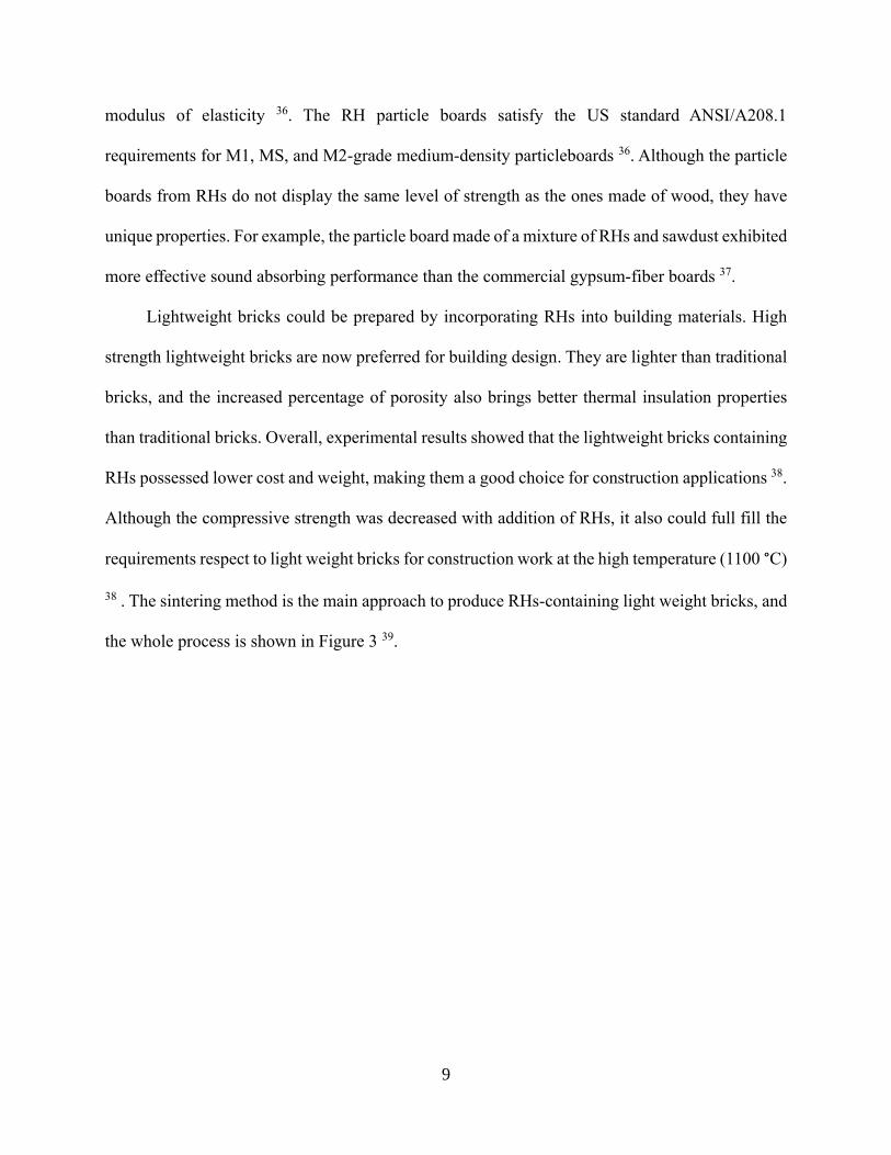
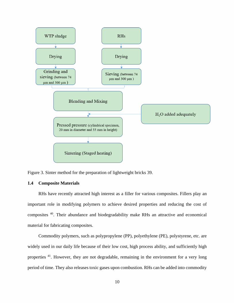
Lightweight bricks could be prepared by incorporating RHs into building materials. High
strength lightweight bricks are now preferred for building design. They are lighter than traditional
bricks, and the increased percentage of porosity also brings better thermal insulation properties
than traditional bricks. Overall, experimental results showed that the lightweight bricks containing
RHs possessed lower cost and weight, making them a good choice for construction applications 38.
Although the compressive strength was decreased with addition of RHs, it also could full fill the
requirements respect to light weight bricks for construction work at the high temperature (1100 °C)
38 . The sintering method is the main approach to produce RHs-containing light weight bricks, and
the whole process is shown in Figure 3 39.
10
Figure 3. Sinter method for the preparation of lightweight bricks 39.
1.4 Composite Materials
RHs have recently attracted high interest as a filler for various composites. Fillers play an
important role in modifying polymers to achieve desired properties and reducing the cost of
composites 40. Their abundance and biodegradability make RHs an attractive and economical
material for fabricating composites.
Commodity polymers, such as polypropylene (PP), polyethylene (PE), polystyrene, etc. are
widely used in our daily life because of their low cost, high process ability, and sufficiently high
properties 41. However, they are not degradable, remaining in the environment for a very long
period of time. They also releases toxic gases upon combustion. RHs can be added into commodity

11
polymers to minimize such issues. RHs can also be incorporate into polymers to increase frictional
properties for certain applications such as PP, PE 42. For example, polyoxymethylene (POM)
composites with 5 wt. % low-density polyethylene (LDPE) and 5 wt. % RHs exhibited better
mechanical strength compared to neat POM 43.
RHs can be used as a filler for rubber composites as well. RHs were used in recycled acrylo
nitrile butadiene rubber (NBRr) for nitrile glove applications 44. This is an attractive composite
using both a natural filler and a recycled material. It was reported that gamma-amino-
propyltrimethoxysilane can effectively treat RHs, generating a more effective reinforcer. The
composites containing treated RHs exhibited a higher tensile strength and modulus, but lower
elongation break than the ones containing untreated RHs 44. In addition, acetylation treated RHs
blend with polystyrene/styrene butadiene rubber were effective in reducing the percentage of water
absorption, because the acetyl groups reduced the hygroscopicity of the RHs 45.
1.5 Sorption of RH applications
RHs are an effective, safe, low-cost agent to sorb metals 46, oil 47, toxics 46b, 48, and dyes 49
from the environment. The earlier researches suggested that both the inorganic silica and organic
lignocellulose in RHs were closely related to the sorption capability 46a, 48, 50. The sorption process
was assumed to be spontaneous and endothermic if the RHs were not treated or modified 46a, 51, as
the sorption occurred at the surface rather than throughout the whole RH 46a. RHs sorption was
assessed under various parameters to observe the highest yielding sorption conditions, as well as
most rapid rate 46a, 47-48, 50-52. The untreated RHs and treated RHs exhibited different adsorption
performances.
Without any treatment, the RHs sorption performance for silver 46a, arsenic 52, lead 46b, and
oils 47a was examined in different experiments. All except oil sorption supported that RHs had the

12
capacity to sorb sufficiently for further consideration of applications 47a. Because RHs have a low
water to oil sorption ratio, the capacity to adsorb diesel, crude oils, new engine and used engine
oils was low and unsuccessful 47a. Four factors could tune the performance of untreated RHs:
optimal pH value, moderate concentration (amounts of RHs and metal ions), enough equilibrium
time, and temperature 46, 52.
Acid or alkali chemical treatment 48-49, 53 or thermal treatment 47b, 47c, 53 of RHs can help
improve the sorption performance of RHs particularly for metal ions, including shortening
equilibrium time and increasing pore volume. Same as the untreated RHs, the optimal pH and
temperature also contribute to the sorption performance of the treated RHs 47c, 48-49.
Overall, treated RHs exhibit higher sorption performance but untreated RHs are more cost-
effective. Using RHs to as a sorb agent is highly beneficial for the environment, since this is a
process to use a biowaste to improve environment.
1.6 Power Generation
Generation of power using RHs was proved successful, yet very not easy to commercialize.
Investigations were conducted on profitability, cost analysis, cost effectiveness, and the
performance of RHs for power generation since the late 1960’s 54. It was reported that RHs could
be used to balance undesired carbon dioxide emissions from energy producing systems including
gasification and combustion 55 . RH power generation could be profitable within larger plants
solely if the surplus electricity generated is sold directly to the national power grid.
The gasification process converts organic carbonaceous materials into CO, H2, and CO2 by
heating them to temperatures above 700 °C with controlled ratios of O2, and produces a synthetic
fuel. Biomass gasification and power generation technologies have been studied since as early as
1960, and RHs gasification has developed significantly since then. According to the collected data,

13
the gasification temperature is related to the heating value returned. The moisture content of RHs
has a great influence on the system and should be preheated to be maintained below 15% to obtain
optimum results 56. It was found that optimum excessive air ratios for the gasification process
range from 0.3-0.6 and has a significant impact on the efficiency of the gasification results. The
study concluded that a continuous power generation of 10 kW was achieved 57.
In comparison with other thermo-chemical power conversion technologies, combustion is
proven to be the most efficient 58. Recently, evaluating the characteristics of generating power
through combustion of RHs alone, as well as being co-fired with equalizing alternatives 58b, 59, such
as sugarcane bagasse and coal. The results showed that the co-fired RHs, mixed with other
components such as coal and sugarcane bagasse, performed better than combusting RHs alone.
Co-fired RHs had lower NO emissions and less O2 production in flue gas than when firing 100%
RHs. Fluid bed combustor (FBC) power generation proved to be a very promising technique,
returning combustion efficiencies ranging from 95.0-99.1% between different FBCs.
1.7 Comprehensive Utilization of RHs
The contents in RHs are complex with multiple possible applications. However, researchers
usually focus on one component during their exploration For example, silica is usually the focus
on research while organic lignocellulose was typically ignored. Comprehensive strategies have
been recently explored. The goal is to increase the utilization efficiency and products diversity of
RH biomass. The basic procedures of the comprehensive strategy is to start with a chemical
pretreatment, such as acid or alkali hydrolysis. By multiple treatments, one or more products can
be obtained in every reaction stage. For example, Zhang et al. 60 used acid hydrolysis as the main
treatment to obtain D-xylose, lignin, ethanol, and superfine silica from RHs. Figure 4 shows the

14
schematic process of extracting several products from RHs. This kind of strategy improves the
utilization efficiency of RH biomass, which is beneficial and highly desirable.
Figure 4. Technological process of comprehensively utilizing RHs 60.
1.8 Conclusion
In brief, RHs are one of abundant biomasses. The remarkable physical and chemical
properties of amorphous silica and lignocellulose give RHs a wide variety of applications including
chemical production, construction materials, sorption materials, power generation, and composite
materials. Biomass comprehensive application strategy is a new concept for solving the problem
of low utilization efficiency and product diversity, which is also the goal of this thesis. Herein,
Chapter 2 reports the extraction of highly active amorphous silica nanoparticles from RHs
for the synthesis of green phosphors, which have applications including plasma displays and
fluorescent lamps. Chapter 3 reports the exploration to obtain both silica nanoparticles and
lignocellulose from RHs. The lignocellulose could be extracted from RHs using an ionic liquid to
prepare aerogels via a freeze-thaw process. By converting the lignocellulose aerogel to be

15
hydrophobic through surface treatment, it could find applications in oil spill remediation. Carbon
aerogel could be further obtained from the lignocellulose aerogel via high temperature calcination.
Silica nanoparticles were also obtained by calcining the RH residue after ionic liquid extraction.
The obtained silica can be applied for various applications. Chapter 4 gives a summary of this
thesis and an outlook.

16
References
1. Gadde, B.; Bonnet, S.; Menke, C.; Garivait, S., Air pollutant emissions from rice straw
open field burning in India, Thailand and the Philippines. Environmental Pollution 2009, 157 (5),
1554-1558.
2. Chen, H.; Wang, W.; Martin, J. C.; Oliphant, A. J.; Doerr, P. A.; Xu, J. F.; DeBorn, K. M.;
Chen, C.; Sun, L., Extraction of lignocellulose and synthesis of porous silica nanoparticles from
rice husks: a comprehensive utilization of rice husk biomass. ACS Sustainable Chemistry &
Engineering 2012, 1 (2), 254-259.
3. Balathanigaimani, M. S.; Kang, H.-C.; Shim, W.-G.; Kim, C.; Lee, J.-W.; Moon, H.,
Preparation of powdered activated carbon from rice husk and its methane adsorption properties.
Korean Journal of Chemical Engineering 2006, 23 (4), 663-668.
4. Jüntgen, H., Activated carbon as catalyst support: a review of new research results. Fuel
1986, 65 (10), 1436-1446.
5. Sircar, S.; Golden, T.; Rao, M., Activated carbon for gas separation and storage. Carbon
1996, 34 (1), 1-12.
6. Ali, I., The quest for active carbon adsorbent substitutes: inexpensive adsorbents for toxic
metal ions removal from wastewater. Separation & Purification Reviews 2010, 39 (3-4), 95-171.
7. Haykiri-Acma, H.; Yaman, S.; Kucukbayrak, S., Gasification of biomass chars in steam–
nitrogen mixture. Energy Conversion and Management 2006, 47 (7), 1004-1013.
8. Lanzetta, M.; Di Blasi, C., Pyrolysis kinetics of wheat and corn straw. Journal of Analytical
and Applied Pyrolysis 1998, 44 (2), 181-192.
9. Minkova, V.; Razvigorova, M.; Bjornbom, E.; Zanzi, R.; Budinova, T.; Petrov, N., Effect
of water vapour and biomass nature on the yield and quality of the pyrolysis products from biomass.
Fuel Processing Technology 2001, 70 (1), 53-61.
10. Zhu, K.; Fu, H.; Zhang, J.; Lv, X.; Tang, J.; Xu, X., Studies on removal of NH 4+-N from
aqueous solution by using the activated carbons derived from rice husk. Biomass and bioenergy
2012, 43, 18-25.
11. Yao, S.; Zhang, J.; Shen, D.; Xiao, R.; Gu, S.; Zhao, M.; Liang, J., Removal of Pb (II) from
water by the activated carbon modified by nitric acid under microwave heating. Journal of colloid
and interface science 2016, 463, 118-127.
12. Mashhadi, S.; Sohrabi, R.; Javadian, H.; Ghasemi, M.; Tyagi, I.; Agarwal, S.; Gupta, V.
K., Rapid removal of Hg (II) from aqueous solution by rice straw activated carbon prepared by
microwave-assisted H 2 SO 4 activation: Kinetic, isotherm and thermodynamic studies. Journal
of Molecular Liquids 2016, 215, 144-153.
13. Lu, C.-Y.; Wey, M.-Y.; Chuang, K.-H., Catalytic treating of gas pollutants over cobalt
catalyst supported on porous carbons derived from rice husk and carbon nanotube. Applied
Catalysis B: Environmental 2009, 90 (3), 652-661.
14. (a) Ganesan, A.; Mukherjee, R.; Raj, J.; Shaijumon, M. M., Nanoporous rice husk derived
carbon for gas storage and high performance electrochemical energy storage. Journal of Porous
Materials 2014, 21 (5), 839-847; (b) Chen, H.; Wang, H.; Xue, Z.; Yang, L.; Xiao, Y.; Zheng, M.;
Lei, B.; Liu, Y.; Sun, L., High hydrogen storage capacity of rice hull based porous carbon.
international journal of hydrogen energy 2012, 37 (24), 18888-18894.
15. Reddy, N.; Yang, Y., Biofibers from agricultural byproducts for industrial applications.
TRENDS in Biotechnology 2005, 23 (1), 22-27.

17
16. Nguyen, T.-D.; Hamad, W. Y.; MacLachlan, M. J., Tuning the iridescence of chiral
nematic cellulose nanocrystals and mesoporous silica films by substrate variation. Chemical
Communications 2013, 49 (96), 11296-11298.
17. Adolfsson, K. H.; Hassanzadeh, S.; Hakkarainen, M., Valorization of cellulose and waste
paper to graphene oxide quantum dots. Rsc Advances 2015, 5 (34), 26550-26558.
18. (a) Focher, B.; Marzetti, A.; Marsano, E.; Conio, G.; Tealdi, A.; Cosani, A.; Terbojevich,
M., Regenerated and graft copolymer fibers from steam‐exploded wheat straw: Characterization
and properties. Journal of Applied Polymer Science 1998, 67 (6), 961-974; (b) Gollapalli, L. E.;
Dale, B. E.; Rivers, D. M., Predicting digestibility of ammonia fiber explosion (AFEX)-treated
rice straw. Springer: 2002; (c) Tilby, S. E., Method and apparatus for processing sugarcane.
Google Patents: 1971.
19. Johar, N.; Ahmad, I.; Dufresne, A., Extraction, preparation and characterization of
cellulose fibres and nanocrystals from rice husk. Industrial Crops and Products 2012, 37 (1), 93-
99.
20. Garcia, M.; Garmendia, I.; Garcia, J., Influence of natural fiber type in eco-composites.
Journal of Applied Polymer Science 2008, 107 (5), 2994-3004.
21. Xu, Y.; Wu, Q.; Lei, Y.; Yao, F.; Zhang, Q., Natural Fiber Reinforced Poly(vinyl chloride)
Composites: Effect of Fiber Type and Impact Modifier. Journal of Polymers and the Environment
2008, 16 (4), 250-257.
22. Yin, X. L.; Wu, C. Z.; Zheng, S. P.; Chen, Y., Design and operation of a CFB gasification
and power generation system for rice husk. Biomass & Bioenergy 2002, 23 (3), 181-187.
23. Bhat, A.; Bheemarasetti, J. V. R.; Rao, T. R., Kinetics of rice husk char gasification. Energy
Conversion and Management 2001, 42 (18), 2061-2069.
24. Zhao, Y.; Sun, S.; Tian, H.; Qian, J.; Su, F.; Ling, F., Characteristics of rice husk
gasification in an entrained flow reactor. Bioresource Technology 2009, 100 (23), 6040-6044.
25. Kuo, H. P.; Pan, S. M.; Hsu, H. T., Comparisons of the hydrogen-rich syngas compositions
from wet rice husk slurry steam reforming reactions using different catalysts. Biomass &
Bioenergy 2011, 35 (7), 3025-3031.
26. (a) Le, D. D.; Xiao, X.; Morishita, K.; Takarada, T., Biomass gasification using nickel
loaded brown coal char in fluidized bed gasifier at relatively low temperature. Journal of Chemical
Engineering of Japan 2009, 42 (1), 51-57; (b) Bona, S.; Guillén, P.; Alcalde, J. G.; García, L.;
Bilbao, R., Toluene steam reforming using coprecipitated Ni/Al catalysts modified with lanthanum
or cobalt. Chemical Engineering Journal 2008, 137 (3), 587-597; (c) Wang, T.; Chang, J.; Wu, C.;
Fu, Y.; Chen, Y., The steam reforming of naphthalene over a nickel–dolomite cracking catalyst.
Biomass and Bioenergy 2005, 28 (5), 508-514.
27. (a) Saha, B. C.; Iten, L. B.; Cotta, M. A.; Wu, Y. V., Dilute acid pretreatment, enzymatic
saccharification, and fermentation of rice hulls to ethanol. Biotechnology Progress 2005, 21 (3),
816-822; (b) Zheng, J.-l.; Zhu, X.-f.; Guo, Q.-x.; Zhu, Q.-s., Thermal conversion of rice husks and
sawdust to liquid fuel. Waste Management 2006, 26 (12), 1430-1435; (c) Zheng, J.-l., Bio-oil from
fast pyrolysis of rice husk: Yields and related properties and improvement of the pyrolysis system.
Journal of Analytical and Applied Pyrolysis 2007, 80 (1), 30-35; (d) Chen, T.; Wu, C.; Liu, R.,
Steam reforming of bio-oil from rice husks fast pyrolysis for hydrogen production. Bioresource
Technology 2011, 102 (19), 9236-9240.
28. Abbas, A.; Ansumali, S., Global potential of rice husk as a renewable feedstock for ethanol
biofuel production. Bioenergy Research 2010, 3 (4), 328-334.

18
29. Bridgwater, A., Principles and practice of biomass fast pyrolysis processes for liquids.
Journal of Analytical and Applied Pyrolysis 1999, 51 (1), 3-22.
30. Chen, T.; Wu, C.; Liu, R.; Fei, W.; Liu, S., Effect of hot vapor filtration on the
characterization of bio-oil from rice husks with fast pyrolysis in a fluidized-bed reactor.
Bioresource Technology 2011, 102 (10), 6178-6185.
31. Safiuddin, M.; Jumaat, M. Z.; Salam, M.; Islam, M.; Hashim, R., Utilization of solid wastes
in construction materials. International Journal of Physical Sciences 2010, 5 (13), 1952-1963.
32. Sisman, C.; Gezer, E.; Kocaman, I., Effects of organic waste (rice husk) on the concrete
properties for farm buildings. Bulgarian Journal of Agricultural Science 2011, 17 (1), 40-48.
33. Ayrilmis, N.; Kwon, J. H.; Han, T. H., Effect of resin type and content on properties of
composite particleboard made of a mixture of wood and rice husk. International Journal of
Adhesion and Adhesives 2012, 38, 79-83.
34. Ciannamea, E. M.; Stefani, P. M.; Ruseckaite, R. A., Medium-density particleboards from
modified rice husks and soybean protein concentrate-based adhesives. Bioresource Technology
2010, 101 (2), 818-825.
35. Cheng, H.; Wartelle, L. H.; Klasson, K. T.; Edwards, J. C., Solid-state NMR and ESR
studies of activated carbons produced from pecan shells. Carbon 2010, 48 (9), 2455-2469.
36. Yat, S. C.; Berger, A.; Shonnard, D. R., Kinetic characterization for dilute sulfuric acid
hydrolysis of timber varieties and switchgrass. Bioresource Technology 2008, 99 (9), 3855-3863.
37. Matsushita, Y.; Yasuda, S., Preparation of anion-exchange resins from pine sulfuric acid
lignin, one of the acid hydrolysis lignins. Journal of Wood Science 2003, 49 (5), 423-429.
38. Chiang, K. Y.; Chou, P. H.; Chien, K. L.; Chen, J. L.; Wu, C. C., Novel Lightweight
Building Bricks Manufactured from Water Treatment Plant Sludge and Agricultural Waste.
Journal of Residuals Science & Technology 2009, 6 (4), 185-191.
39. Chiang, K.-Y.; Chou, P.-H.; Hua, C.-R.; Chien, K.-L.; Cheeseman, C., Lightweight bricks
manufactured from water treatment sludge and rice husks. Journal of hazardous materials 2009,
171 (1), 76-82.
40. Kord, B., NANOFILLER REINFORCEMENT EFFECTS ON THE THERMAL,
DYNAMIC MECHANICAL, AND MORPHOLOGICAL BEHAVIOR OF HDPE/RICE HUSK
FLOUR COMPOSITES. Bioresources 2011, 6 (2), 1351-1358.
41. Arora, A.; Padua, G., Review: nanocomposites in food packaging. Journal of Food science
2010, 75 (1), R43-R49.
42. (a) Yang, H.-S.; Kim, H.-J.; Son, J.; Park, H.-J.; Lee, B.-J.; Hwang, T.-S., Rice-husk flour
filled polypropylene composites; mechanical and morphological study. Composite Structures 2004,
63 (3), 305-312; (b) Hardinnawirda, K. The effect of rice husks as filler in polymer matrix
composites. Universiti Malaysia Pahang, 2012; (c) Kim, H.-S.; Yang, H.-S.; Kim, H.-J.; Park, H.-
J., Thermogravimetric analysis of rice husk flour filled thermoplastic polymer composites. Journal
of Thermal Analysis and Calorimetry 2004, 76 (2), 395-404.
43. Li, K.; Xiang, D.; Lei, X., Green and self-lubricating polyoxymethylene composites filled
with low-density polyethylene and rice husk flour. Journal of Applied Polymer Science 2008, 108
(5), 2778-2786.
44. Santiagoo, R.; Ismail, H.; Hussin, K., Mechanical properties, water absorption, and
swelling behaviour of rice husk powder filled polypropylene/recycled acrylonitrile butadiene
rubber (PP/NBRr/RHP) biocomposites using silane as a coupling agent. BioResources 2011, 6 (4),
3714-3726.

19
45. Zurina, M.; Ismail, H.; Bakar, A. A., Rice husk powder-filled polystyrene/styrene
butadiene rubber blends. Journal of Applied Polymer Science 2004, 92 (5), 3320-3332.
46. (a) Zafar, S.; Khalid, N.; Mirza, M. L., Potential of rice husk for the decontamination of
silver ions from aqueous media. Separation Science and Technology 2012, 47 (12), 1793-1801; (b)
Singha, B.; Das, S. K., Removal of Pb (II) ions from aqueous solution and industrial effluent using
natural biosorbents. Environmental science and pollution research 2012, 19 (6), 2212-2226.
47. (a) Ali, N.; El-Harbawi, M.; Jabal, A. A.; Yin, C.-Y., Characteristics and oil sorption
effectiveness of kapok fibre, sugarcane bagasse and rice husks: oil removal suitability matrix.
Environmental technology 2012, 33 (4), 481-486; (b) Kenes, K.; Yerdos, O.; Zulkhair, M.; Yerlan,
D., Study on the effectiveness of thermally treated rice husks for petroleum adsorption. Journal of
Non-Crystalline Solids 2012, 358 (22), 2964-2969; (c) Angelova, D.; Uzunov, I.; Uzunova, S.;
Gigova, A.; Minchev, L., Kinetics of oil and oil products adsorption by carbonized rice husks.
Chemical Engineering Journal 2011, 172 (1), 306-311.
48. Hsu, S.-T.; Pan, T.-C., Adsorption of paraquat using methacrylic acid-modified rice husk.
Bioresource technology 2007, 98 (18), 3617-3621.
49. Chakraborty, S.; Chowdhury, S.; Saha, P. D., Adsorption of crystal violet from aqueous
solution onto NaOH-modified rice husk. Carbohydrate Polymers 2011, 86 (4), 1533-1541.
50. (a) Low, K. S.; Lee, C. K.; Wong, S. Y.; Tang, P. L., Metal soprtion enhancement of rice
hull through chemical modification. Environmental Technology 2000, 21 (11), 1239-1243; (b)
Chakraborty, S.; Chowdhury, S.; Das Saha, P., Adsorption of Crystal Violet from aqueous solution
onto NaOH-modified rice husk. Carbohydrate Polymers 2011, 86 (4), 1533-1541.
51. Singha, B.; Das, S. K., Removal of Pb(II) ions from aqueous solution and industrial effluent
using natural biosorbents. Environmental Science and Pollution Research 2012, 19 (6), 2212-2226.
52. Amin, M. N.; Kaneco, S.; Kitagawa, T.; Begum, A.; Katsumata, H.; Suzuki, T.; Ohta, K.,
Removal of arsenic in aqueous solutions by adsorption onto waste rice husk. Industrial &
engineering chemistry research 2006, 45 (24), 8105-8110.
53. Low, K.; Lee, C.; Wong, S.; Tang, P., Metal soprtion enhancement of rice hull through
chemical modification. Environmental technology 2000, 21 (11), 1239-1244.
54. Yin, X. L.; Wu, C. Z.; Zheng, S. P.; Chen, Y., Design and operation of a CFB gasification
and power generation system for rice husk. Biomass and Bioenergy 2002, 23 (3), 181-187.
55. Thao, P. T. M.; Kurisu, K. H.; Hanaki, K., Evaluation of strategies for utilizing rice husk
based on life cycle cost analysis in relation to Greenhouse Gas emissions in An Giang province,
Vietnam. biomass and bioenergy 2012, 37, 122-131.
56. Wu, C.-z.; Yin, X.-l.; Ma, L.-l.; Zhou, Z.-q.; Chen, H.-p., Operational characteristics of a
1.2-MW biomass gasification and power generation plant. Biotechnology advances 2009, 27 (5),
588-592.
57. Yoon, S. J.; Son, Y.-I.; Kim, Y.-K.; Lee, J.-G., Gasification and power generation
characteristics of rice husk and rice husk pellet using a downdraft fixed-bed gasifier. Renewable
Energy 2012, 42, 163-167.
58. (a) Singh, R. I.; Mohapatra, S.; Gangacharyulu, D., Studies in an atmospheric bubbling
fluidized-bed combustor of 10MW power plant based on rice husk. Energy Conversion and
Management 2008, 49 (11), 3086-3103; (b) Sathitruangsak, P.; Madhiyanon, T.; Soponronnarit,
S., Rice husk co-firing with coal in a short-combustion-chamber fluidized-bed combustor (SFBC).
Fuel 2009, 88 (8), 1394-1402.
59. (a) Kuprianov, V. I.; Janvijitsakul, K.; Permchart, W., Co-firing of sugar cane bagasse with
rice husk in a conical fluidized-bed combustor. Fuel 2006, 85 (4), 434-442; (b) Madhiyanon, T.;

20
Sathitruangsak, P.; Soponronnarit, S., Co-firing characteristics of rice husk and coal in a cyclonic
fluidized-bed combustor (Ψ-FBC) under controlled bed temperatures. Fuel 2011, 90 (6), 2103-
2112.
60. Zhang, H.; Ding, X.; Chen, X.; Ma, Y.; Wang, Z.; Zhao, X., A new method of utilizing rice
husk: consecutively preparing d-xylose, organosolv lignin, ethanol and amorphous superfine silica.
Journal of hazardous materials 2015, 291, 65-73.

21
Chapter 2. Synthesis of Green Phosphor from Highly Active Amorphous Silica Derived
from Rice Husks
2.1 Introduction
Rice husks are one of the largest sources of biomass in the world because of the enormous
amount of rice consumed globally every year 1. In the past, RHs were mainly treated as a waste;
they were often disposed of by open-field burning, especially in developing countries, leading to
significant air pollution 2. RHs contain two major components: silica (ca. 15-28 wt. %) and
lignocellulose (LC, ca. 72-85 wt. %) 3, both of which can find a wide range of applications. For
example, syngas and biofuel, which are promising power alternatives, can be synthesized from RH
LC via hydrolysis and fermentation, respectively 4.Silica, the major inorganic component of RH,
is an essential chemical widely used as a catalyst support 5, adsorption material 6, and raw material
for various silicon-based chemicals 7. This silica source is promising for industry applications
because of the facile and low power consumption production, and low price. Several methods have
been developed to prepare silica from RHs, including thermal decomposition method (calcination)
8, hydrothermal reaction 9, and fungus biotransformation method 10. Direct calcination is usually
preferred in industry due to its low cost. The purity of the silica derived from RHs could reach
99.8% after calcination 11. This suggests that the RH silica can be a valid resource for many silica-
related applications.
Recently, many new silicate applications were developed from RH silica. For example,
silicate pigments of multiple colors, which can be applied for ceramic materials and glaze, were
reported by doping silicates from RH silica with different elements 11. Sodium silicate was also
prepared from RH silica, which served as a solid catalyst for transesterification reaction of oil to
biodiesel, and exhibited high performance 12. Magnesium silicate synthesized from RH silica was

22
used to catalyze a ring-opening reaction to synthesize propranolol glycol from glycidol and 1-
naphthol and achieved a conversion rate of 85% 13.
Phosphors have widespread application, including plasma display (PDP), phosphor
thermometry, and fluorescent lamps 14. While many natural phosphors have been discovered, with
an increasing market demand for phosphorescent materials, developing methods to prepare
artificial phosphors is necessary. For example, green artificial silicate phosphor can be made by
doping Zn2SiO4 with Mn2+, in which Mn2+ cations partly replace the positions of the Zn2+ cations,
resulting in a broad emission band under UV light excitation 15. Three common doping methods
have been reported, including solid-state calcination 16, hydrothermal treatment 16-17 and sol-gel
method 16, 18. Demands for phosphors keep increasing, so facile process to prepare phosphors using
inexpensive raw materials are highly desirable.
In this paper, we report our exploration to extract high purity amorphous silica from RHs
by calcination and use the synthesized RH silica to make green phosphors. Various parameters
were adjusted to achieve the highest luminescence. Considering this is a very facile method to
synthesize phosphors at a low cost, it may be further developed for commercial production of
phosphors for practical applications.
2.2 Experiment
2.2.1 Preparation of silica from RHs
The RH sample (from Rice Hull Specialty Products, Inc., Stuttgart, AR) was pretreated by
10% hydrochloric acid (HCl, 35%, Fisher Scientific) at 95 °C for 2 hours. The sample was rinsed
by deionized water three times to eliminate the residual components. Then, it was dried in an oven
at 80 °C for 24 hours. After the sample was completely dried, it was grinded for further use. A

23
sample of 3 g RH was treated in a tube furnace under air atmosphere at 700 °C for 2 hours.5a, 8, 11
After that, 0.72 ± 0.02 g silica was obtained.
2.2.2 Preparation of Zn2SiO4:Mn2+
The silica sample was mixed with zinc nitrate hexahydrate (99 %, Alfa Aesar, USA) and
manganese (II) nitrate tetrahydrate (98 %, Alfa Aesar) in a mortar until all the powders were
uniform. The concentration control of Zn2SiO4:Mn2+ from 4% to 12%. Then the powder sample
underwent calcination in a tube furnace under nitrogen atmosphere. The reacting temperature for
each sample was controlled from 1000-1200 °C, and the reaction last for 4 hours. The control
phosphor samples were prepared by silicic acid 19 (99.9 %, Sigma-Aldrich, USA) or silica (99.5 %,
325 mesh, Alfa Aesar, USA) 20. After the reaction, the samples were ground for further
characterization.
2.2.3 Characterization
The silica sample and phosphor samples were characterized by X-ray diffraction (XRD;
Bruker D2, 40 KV and 30 mA) using a graphite monochromator with Cu Kα radiation (λ=0.1540
nm). In order to analyze the surface area of RH silica, nitrogen adsorption-desorption isotherms
was recorded by Quantachrome NOVA 2000e. And the specific surface area was calculated by
Brunauer-Emmett-Teller (BET) theory. The excitation, decay lifetime, and emission spectra of the
powder samples were measured using an Edinburgh Instruments FLS980 fluorometer system. For
the absolute quantum yield (QY) measurements, and to compare the intensities between the
samples, an integrating sphere was employed in the FLS980 fluorometer 21.
To be consistent, the sample weight (20 mg) and monochromator slit size (3 nm for both
excitation and emission monochromators) were kept for all experiments. Photoluminescence (PL)
spectra from 400-700 nm and excitation spectra of 235-325 nm were collected after diffuse
24
reflectance from the samples, relative to a non-absorbing standard at the excitation wavelength,
and emission spectra were collected under the same conditions. QY was measured by finding the
ratio of the area under the emission spectra to the difference in corrected area under the diffuse
reflectance of the excitation spectra for the sample and the reference. It was calculated based on
the equation below:
samplereference
sample
abs
em
absorbed
emitted
AA
A
dN
dN
NP
NPQY
(1)
Including all the possible errors, such as reflectivity of the reference (< 3 %), particle size
effects (< 2 %), and diffuse reflectance from the sample holder (< 3 %), the estimated error in QY
was about 10 %. Similarly, the estimated fluctuation for excitation power was about 2 %. The
excitation power was measured to be 6 mW.
2.3 Results and Discussion
Figure 5 shows the flow chart to prepare RH phosphor. The original RH treated by diluted
HCl. Weighing 3 g treated RH into alumina crucible and the highly active amorphous silica was
extracted from treated RH under air atmosphere at 700 °C for 2 hours. By mixing and grounding
RH silica with Zn(NO3)2•6H2O and Mn(NO3)2•4H2O, RH phosphor was obtained under N2
atmosphere at 1200 °C. Under UV light, the white powder of RH phosphor emitted intensive green
light.
25
Figure 5. Steps to make RH-silica based green phosphors.
White silica powders were easily synthesized from the HCl pretreated RHs via calcination, as
shown in Figure 6. The broad diffraction band from 15 ° to 40 ° in the XRD pattern in Figure 2
shows that the RH silica was amorphous, consistent with the literature 11, mainly because the HCl
pretreatment eliminated metal ions, particularly K+ cations, which could catalyze the melting of
silica. The amorphous nature and high specific surface area (354.6 m2/g) of RH silica indicate its
high reactivity during the synthesis of silicate phosphors.

26
Figure 6. X-ray diffraction of the synthesized RH silica. The inset figure (a) is a digital picture of
the sample; figure (b) is SEM of RH-silica nanoparticles
In commercial Zn2SiO4:Mn2+ phosphor, the Mn2+ doping concentration is typically 8% (i.e.,
Zn2SiO4:0.08Mn2+), as the Zn2SiO4:Mn2+ phosphor usually exhibits the highest intensity at such
as doping concentration 22. As such, we adopt this doping concentration to explore the
Zn2SiO4:Mn2+ synthesized from RH silica under various temperatures.
The RH phosphor samples were prepared by high temperature pyrolysis, during which RH
silica, Zn(NO3)2·6H2O, and Mn(NO3)2·4H2O were mixed under nitrogen atmosphere at high
conditioning temperatures (1000, 1100, and 1200 °C) for 4 hours. The XRD patterns of
10 15 20 25 30 35 40 45 50
(a)
(a)(a)
RH-silica
nanoparticles
RH-silica
Rel
ativ
e In
ten
sity
(a.
u.)
2-Theta (degrees)
(b)
specific surface area:
354.6 m2/g
27
Zn2SiO4:0.08Mn2+ under different reaction temperatures are shown in Figure 7. All the patterns
exhibit sharp and intense peaks, indicating highly crystallized structures. The XRD patters of the
samples calcined at 1000 and 1100 °C showed that transition phases were still present, as
evidenced by the characteristic peaks of ZnO at 2θ = 36.12°, 47.52°,62.86° and 67.96° 23. When
the temperature reached 1200 °C, the pattern did not show any impurity phases compared to the
standard data (ICSD card No. 16172). This suggests that the reaction among RH silica,
Zn(NO3)2·6H2O, and Mn(NO3)2·4H2O was completed, and the well-crystallized Zn2SiO4 with
Mn2+ doped through its lattice was obtained at 1200 °C 23. The appearances of the samples under
visible light and 256 nm UV light excitation are shown in Figure 8, which showed that the color
of the samples gradually changed from brown/grey to off-white. Based on rough visual inspection,
all samples emitted green light, and a clear positive correlation between the emission intensity and
the reaction temperature was observed. Considering single phase Zn2SiO4:0.08Mn2+ was
successfully synthesized at 1200 °C, higher temperature reaction conditions were not explored
mainly out of the consideration of energy saving for potential future industrial production.

28
Figure 7. X-ray diffraction patterns of Zn2SiO4:0.08Mn2+ phosphors synthesized at
temperatures of 1000, 1100, and 1200 °C under N2 atmosphere for 4 hours.
10 20 30 40 50 60 70 80 90
Zn2SiO
4 ICSD No. 16172
ZnO
1000 C
1100 C
Rel
ativ
e in
tnes
ity
(a.
u.)
2 - Theta (degrees)
Zn2SiO
4:0.08Mn2+
1200 C

29
Figure 8. Appears of the RH phosphor samples prepared at different temperatures: 1000 °C (A and
D), 1100 °C (B and E), and 1200 °C (C and F) under visible light (A-C) and 256 nm UV light (D-
F). Scale bars represent 1 cm.
Figure 9a shows the PL spectra of the RH phosphor samples under 258 nm excitation. All
the three PL spectra peaked at ca. 527 nm, corresponding to the electronic transition from 4T1 to
6A1 that limited the emission transition of Mn2+. After excitation, the electrons returned to the
ground state, and a green emission was observed 23a. With an increasing reaction temperature, the
PL intensity was improved significantly, well corresponding to the visual inspection under 254 nm
UV light excitation as shown in Figure 4D-4F. The optimum PL intensity was achieved at a
calcination temperature of 1200°C. According to Figure 9b, the quantum yield, which is the
percentage of the excited electrons returned to the ground state, was improved with an increasing
reaction temperature. Overall, the XRD patterns, visual inspection, PL intensity, and quantum
30
yields all indicate that a high reaction temperature of 1200 °C resulted in high quality phosphor
derived from RH silica. Although sol-gel methods could better control the size of the phosphors,
the high cost and the health and environmental issues associated with the sol-gel process are key
drawbacks. The synthesis of phosphor derived using RH silica is appealing for sustainable
development and is affordable.
Figure 9. (a) PL spectra of the zinc silicate derived from the RH-silica under different temperatures.
(b) The quantum yield variation of the samples corresponding to the PL spectra.
475 500 525 550 575 600
1000 °C
1100 °C
Inte
nsi
ty (
a.u
.)
Wavelength (nm)
1200 °C
Zn2SiO4:0.08Mn2+
ex= 258 nm
(a)
1000 1100 12000
10
20
30
40
50
60
Zn2SiO4:0.08Mn2+
ex= 258 nm
Quan
tum
Yie
ld (
%)
Temperature (C)
(b)

31
Composition is another key factor that influences the PL performance of silicate phosphors
24. As such, the doping concentration in Zn2SiO4:Mn2+, was adjusted to be 4%, 6%, 8%, 10%, 12%
through the initial formulation. Based on the results above, all the samples were synthesized under
the optimum reaction temperature of 1200 °C for 4 hours. The XRD patterns in Figure 10 indicate
that all the samples doped with different concentrations of Mn could successfully form Zn2SiO4
single phase, as compared with the simulated pattern. This indicates that within certain range,
doping concentration does not influence the formation of Zn2SiO4. All the samples are white
powders, and they all emit high intensity green light under 258 nm UV light excitation. As
expected, the PL emission intensity of the phosphors was affected by doping concentration. Figure
11a shows that the PL intensity of the doped phosphors was increased with an increasing Mn2+
doping concentration up to 6%, and then decreased with a further increase of Mn2+ doping
concentration, probably due to the quenching concentration effect. It is resulted from the excited
and unexcited activation interactions, leading to the excitation energy going down to the quenching
sites 23a, 25. According to Figure 11b, the quantum yield exhibited the same trend as the PL emission
intensity. The broad PL spectra covered most of the visible light range, which is advantageous for
such RH derived phosphors for various applications, such as LED lights, phosphor thermometry,
toys, and lights for room decoration. To be noted, Figure 11 also shows that the Zn2SiO4:0.06Mn2+
RH phosphor with concentration exhibited slightly higher PL intensity than Zn2SiO4:0.08Mn2+ ,
which was the concentration typically adopted by the commercial phosphors.

32
Figure 10. Powder X-ray diffraction patterns of the Zn2SiO4:Mn2+ phosphors combustion-
synthesized under different doping concentrations under 1200°C for 4h.
10 20 30 40 50 60 70 80 90
Zn2SiO
4:0.04Mn
2+
Zn2SiO
4:0.06Mn
2+
Zn2SiO
4:0.10Mn
2+
Zn2SiO
4:0.12Mn
2+
Zn2SiO
4:0.08Mn
2+
Rel
ativ
e in
tensi
ty (
a.u.)
2 - Theta (degrees)
Zn2SiO
4 ICSD No. 16172
33
Figure 11. (a) PL spectra of the Zinc silicate derived from the RH-silica under different Mn2+
doped concentrations. (b) The quantum yield variation of the samples corresponding to the PL
spectra.
475 500 525 550 575 600
Zn2SiO4:0.12Mn2+
Zn2SiO4:0.10Mn2+
Zn2SiO4:0.08Mn2+
Zn2SiO4:0.06Mn2+
Inte
nsi
ty (
a.u.)
Wavelength (nm)
Zn2SiO4:0.04Mn2+
T = 1200C
ex
= 258 nm
(a)
0.04 0.06 0.08 0.10 0.120
10
20
30
40
50
Quan
tum
Yie
ld (
%)
Doping Concentration
Zn2SiO4:Mn2+
ex
= 258 nm
(b)

34
Figure 12 shows the decay curve of Zn2SiO4:0.06Mn2+ sample excited by 258 nm to
analyze the life time of the transition from 4T1 to 6A1. The curve fit a multi exponential function
represented as
𝐼(𝑡) = 𝐴1𝑒(−
𝑡𝜏1
)+ 𝐴2𝑒
(−𝑡
𝜏2),
where t represents time, τ1 and τ2 are two different fluorescence decay times, and A1 and A2 are the
fit constants with values of 24 and 76, respectively 23a. The fit of the kinetics for
Zn2SiO4:0.06Mn2+at 527 nm showed an average of 20 % contribution from the short (τ1)
component and 80 % contribution from the long (τ2) component. The calculated lifetime values
are τ1 = 1.023 ms and τ2 = 6.2 ms. The average decay time τ could be modeled with the equation
below26:
2 21 1 2 2
1 1 2 2
A A
A A
(2)
Therefore, the average decay lifetime was 5.94 ± 0.12 ms. This value is shorter than the reported
data ranges of 8-16 ms 27, which is advantageous for applications such as PDP.

35
Figure 12. Decay curve of the green emission at 527 nm under 258 excitation from the
Zn2SiO4:0.06Mn2+ phosphor.
The high price of commercial phosphors is the main disadvantage for their applications in
industry. RH silica could be an appealing alternative to significantly lower the price of phosphors
for wider applications. To insure quality, control silicate phosphor samples were synthesized under
N2 atmosphere at 1200 °C for 4 hours from silicic acid 19 and commercial silica 20, which were
used in the production of commercial phosphors, with the same doping concentration
Zn2SiO4:0.08Mn2+ 23a for comparison. All samples were white powders and emitted highly
intensive green light, hard to be differentiated by the naked eyes. Figure 13a shows the PL
excitation spectra of the phosphors derived from commercial silica, RH silica, and silicic acid. The
0 5 10 15 20
0.01
0.1
1
Zn2SiO4:0.06Mn2+
ex
= 258 nm ;em
= 527 nm
T = 1200 C ; t = 4 h
Log (
Inte
nsi
ty)
Decay Time (ms)

36
results showed that the phosphor from commercial silica exhibited the lowest intensity and the one
derived from silicic acid exhibited the highest intensity under 258 nm excitation. The quantum
yield of the samples followed the same trend as their PL intensity, as shown in Figure 13b. These
results showed that RH phosphor exhibited PL performance than the phosphor from commercial
silica. This is probably due to the high specific surface area of RH silica, which contributes to a
large interface between the reactants, reducing the diffusion distance between silica and metal
nitrates, leading to improved reaction kinetics between the silica and metal nitrates. The phosphor
from the silicic acid exhibited the best PL performance. However, silicic acid is not an appealing
material to synthesize phosphors due to its high cost. Although the RH biomass phosphor did not
outperform silicic acid, it still reached 70% efficiency of the phosphor from silicic acid.
Considering preparing silica from RHs is cost effective and energy efficient, and the PL property
is better than the phosphor from the commercial silica, therefore RH phosphor represents a viable
alternative, which could be beneficial for applications in industries.

37
Figure 13. (a) PL spectra of the zinc silicate derived from the RH-silica, commercially-used silica,
and silicic acid. (b) The quantum yield variation of the sample corresponding to the PL spectra.
475 500 525 550 575 600
Silicic
Acid
RH-silica
Inte
msi
ty (
a.u.)
Wavelength (nm)
Commercial silica
Zn2SiO4:0.08Mn2+;
1200C ; ex= 258 nm
(a)
quartz silica RH-silica silicic acid0
10
20
30
40
50
60
70
Qu
antu
m Y
ield
(%
) ex= 258 nm
(b)

38
2.4 Conclusion
In summary, amorphous silica was extracted from acid-treated RH biomass by using the
direct calcination method. After mixing RH-silica, Zn2+, and Mn2+ related metal salts,
Zn2SiO4:Mn2+ green phosphor was obtained via high temperature pyrolysis. By controlling the
temperature and Mn2+ doping concentration, the optimum reaction conditions were found. Under
such conditions, the sample of Zn2SiO4:0.08Mn2+ after treatment at 1200 °C for 4 hours was
obtained. Compared to the sample made from silicic acid and commercially-used silica, PL
intensity and quantum yield of the RH silicate phosphor was better than the sample derived from
commercially-used silica and reached 70 % efficiency of the sample made from silicic acid. The
results showed that the phosphor derived from RH can serve as an alternative to commercially-
used phosphor due to its favorable properties and inexpensive green resource.

39
References
1. (a) Soltani, N.; Bahrami, A.; Pech-Canul, M.; González, L., Review on the
physicochemical treatments of rice husk for production of advanced materials. Chemical
engineering journal 2015, 264, 899-935; (b) Pode, R., Potential applications of rice husk ash waste
from rice husk biomass power plant. Renewable and Sustainable Energy Reviews 2016, 53, 1468-
1485.
2. Gadde, B.; Bonnet, S.; Menke, C.; Garivait, S., Air pollutant emissions from rice straw
open field burning in India, Thailand and the Philippines. Environmental Pollution 2009, 157 (5),
1554-1558.
3. Chen, H.; Wang, W.; Martin, J. C.; Oliphant, A. J.; Doerr, P. A.; Xu, J. F.; DeBorn, K. M.;
Chen, C.; Sun, L., Extraction of lignocellulose and synthesis of porous silica nanoparticles from
rice husks: a comprehensive utilization of rice husk biomass. ACS Sustainable Chemistry &
Engineering 2012, 1 (2), 254-259.
4. Saha, B. C.; Cotta, M. A., Lime pretreatment, enzymatic saccharification and fermentation
of rice hulls to ethanol. Biomass and Bioenergy 2008, 32 (10), 971-977.
5. (a) Li, Y.; Lan, J. Y.; Liu, J.; Yu, J.; Luo, Z.; Wang, W.; Sun, L., Synthesis of Gold
Nanoparticles on Rice Husk Silica for Catalysis Applications. Industrial & Engineering Chemistry
Research 2015, 54 (21), 5656-5663; (b) Artkla, S.; Kim, W.; Choi, W.; Wittayakun, J., Highly
enhanced photocatalytic degradation of tetramethylammonium on the hybrid catalyst of titania and
MCM-41 obtained from rice husk silica. Applied Catalysis B: Environmental 2009, 91 (1), 157-
164.
6. Adam, F.; Chua, J.-H., The adsorption of palmytic acid on rice husk ash chemically
modified with Al (III) ion using the sol–gel technique. Journal of colloid and interface science
2004, 280 (1), 55-61.
7. Wang, W.; Martin, J. C.; Huang, R.; Huang, W.; Liu, A.; Han, A.; Sun, L., Synthesis of
silicon complexes from rice husk derived silica nanoparticles. RSC Advances 2012, 2 (24), 9036-
9041.
8. (a) Wang, W.; Martin, J. C.; Fan, X.; Han, A.; Luo, Z.; Sun, L., Silica nanoparticles and
frameworks from rice husk biomass. ACS applied materials & interfaces 2012, 4 (2), 977-981; (b)
Wang, W.; Martin, J. C.; Zhang, N.; Ma, C.; Han, A.; Sun, L., Harvesting silica nanoparticles from
rice husks. Journal of Nanoparticle Research 2011, 13 (12), 6981-6990.
9. Sun, L.; Gong, K., Silicon-Based Materials from Rice Husks and Their Applications.
Industrial & Engineering Chemistry Research 2001, 40 (25), 5861-5877.
10. Pineda-Vasquez, T. G.; Casas-Botero, A. E.; Ramírez-Carmona, M. E.; Torres-Taborda,
M. M.; Soares, C. H.; Hotza, D., Biogeneration of Silica Nanoparticles from Rice Husk Ash Using
Fusarium oxysporum in Two Different Growth Media. Industrial & Engineering Chemistry
Research 2014, 53 (17), 6959-6965.
11. Wang, Z.; Chen, H.; Xu, L.; Xu, S. Q.; Gao, C. F.; Oliphant, A. J.; Liu, J.; Lu, Y.; Wang,
W.; Sun, L., Synthesis and colour prediction of stable pigments from rice husk biomass. Green
Materials 2015, 3 (1), 10-14.
12. Roschat, W.; Siritanon, T.; Yoosuk, B.; Promarak, V., Rice husk-derived sodium silicate
as a highly efficient and low-cost basic heterogeneous catalyst for biodiesel production. Energy
Conversion and Management 2016, 119, 453-462.

40
13. Fernandes, G. P.; Yadav, G. D., Atom-Economical Selective-Ring-Opening Reaction of
Glycidol with 1-Naphthol Catalyzed by Magnesium Silicate of a Biogenic Silica Source. Industrial
& Engineering Chemistry Research 2015, 54 (42), 10245-10252.
14. Lojpur, V.; Nikolić, M.; Jovanović, D.; Medić, M.; Antić, Ž.; Dramićanin, M.,
Luminescence thermometry with Zn2SiO4: Mn2+ powder. Applied Physics Letters 2013, 103 (14),
141912.
15. Wang, L.; Liu, X.; Hou, Z.; Li, C.; Yang, P.; Cheng, Z.; Lian, H.; Lin, J., Electrospinning
synthesis and luminescence properties of one-dimensional Zn2SiO4: Mn2+ microfibers and
microbelts. The Journal of Physical Chemistry C 2008, 112 (48), 18882-18888.
16. Wang, Y.; Hao, Y.; Yuwen, L., Synthesis process dependent photoluminescent properties
of Zn2SiO4: Mn2+ upon VUV region. Journal of alloys and compounds 2006, 425 (1), 339-342.
17. Yu, X.; Wang, Y., Synthesis and VUV spectral properties of nanoscaled Zn 2 SiO 4: Mn
2+ green phosphor. Journal of Physics and Chemistry of Solids 2009, 70 (8), 1146-1149.
18. Lukić, S.; Petrović, D.; Dramićanin, M.; Mitrić, M.; Ðačanin, L., Optical and structural
properties of Zn2SiO4: Mn2+ green phosphor nanoparticles obtained by a polymer-assisted sol–gel
method. Scripta Materialia 2008, 58 (8), 655-658.
19. Kasenga, A. F.; Gray, L. F.; Henson, T. L.; Macinnis, M. B., Method for a producing
manganese activated zinc silicate phosphor. Google Patents: 1990.
20. (a) King, E., Heats of Formation of Crystalline Calcium Orthosilicate, Tricalcium Silicate
and Zinc Orthosilicate1. Journal of the American Chemical Society 1951, 73 (2), 656-658; (b)
Takesue, M.; Hayashi, H.; Smith, R. L., Thermal and chemical methods for producing zinc silicate
(willemite): a review. Progress in Crystal Growth and Characterization of Materials 2009, 55 (3),
98-124.
21. (a) Pokhrel, M.; Wahid, K.; Mao, Y., Systematic Studies on RE2Hf2O7: 5% Eu3+ (RE= Y,
La, Pr, Gd, Er, and Lu) Nanoparticles: Effects of the A-Site RE3+ Cation and Calcination on
Structure and Photoluminescence. The Journal of Physical Chemistry C 2016; (b) Pokhrel, M.;
Kumar, G.; Ma, C.-G.; Brik, M.; Langloss, B. W.; Stanton, I. N.; Therien, M. J.; Sardar, D.; Mao,
Y., Electronic and optical properties of Er-doped Y2O2S phosphors. Journal of Materials
Chemistry C 2015, 3 (43), 11486-11496.
22. (a) Liu, J.; Wang, Y.; Yu, X.; Li, J., Enhanced photoluminescence properties of Zn2SiO4:
Mn2+ co-activated with Y3+/Li+ under VUV excitation. Journal of Luminescence 2010, 130 (11),
2171-2174; (b) Morell, A.; El Khiati, N., Green phosphors for large plasma TV screens. Journal
of The Electrochemical Society 1993, 140 (7), 2019-2022.
23. (a) Lu, Q.; Wang, P.; Li, J., Structure and luminescence properties of Mn-doped Zn 2 SiO
4 prepared with extracted mesoporous silica. Materials Research Bulletin 2011, 46 (6), 791-795;
(b) Li, Z.; Zhang, H.; Fu, H., Facile synthesis and morphology control of Zn2SiO4:Mn
nanophosphors using mesoporous silica nanoparticles as templates. Journal of Luminescence 2013,
135, 79-83.
24. (a) Alaparthi, S. B.; Lu, L.; Tian, Y.; Mao, Y., Europium doped lanthanum zirconate
nanoparticles with high concentration quenching. Materials Research Bulletin 2014, 49, 114-118;
(b) Pokhrel, M.; Valdes, C.; Mao, Y., Ultraviolet upconversion enhancement in triply doped
NaYF4: Tm3+, Yb3+ particles: The role of Nd 3+ or Gd 3+ Co-doping. Optical Materials 2016, 58,
67-75.
25. (a) Thiyagarajan, P.; Kottaisamy, M.; Rao, M. R., Structural and luminescence properties
of pulsed laser deposited green-emitting Zn2SiO4: Mn phosphor thin films. Scripta materialia 2007,
57 (5), 433-436; (b) Kang, Z.; Liu, Y.; Wagner, B.; Gilstrap, R.; Liu, M.; Summers, C.,

41
Luminescence properties of Mn2+ doped Zn2SiO4 phosphor films synthesized by combustion CVD.
Journal of luminescence 2006, 121 (2), 595-600.
26. Fujii, T.; Kodaira, K.; Kawauchi, O.; Tanaka, N.; Yamashita, H.; Anpo, M., Photochromic
behavior in the fluorescence spectra of 9-anthrol encapsulated in Si-Al glasses prepared by the sol-
gel method. The Journal of Physical Chemistry B 1997, 101 (50), 10631-10637.
27. Rao, R.; Devine, D., RE-activated lanthanide phosphate phosphors for PDP applications.
Journal of Luminescence 2000, 87, 1260-1263.

42
Chapter 3. Self-Assembled Multifunctional Lignocellulose Aerogel and Silica Nanoparticles
from Rice Husks: a Comprehensive Utilization Strategy
3.1 Introduction
Rice husks (RHs) are one of the most abundant sources of biomass in the world, due to the
massive amount of rice consumption by human population. There are two main components in
RHs: silica (ca.15-28 wt. %) and lignocellulose (LC) (ca.72-85 wt. %) 1. If isolated, the silica from
RHs could be used to prepare various silicon-based materials, including silicon carbide 2, silicon
nitride 3, silicon tetrachloride 4, silicon 5, and zeolite 6. These materials have widespread
application in semiconductor materials 6, abrasive materials 6, pigments 7, catalyst supports 8, etc.
LC is a complex of organic materials, which includes lignin, cellulose, and hemicellulose 9. LC
could be considered as a resource for various biochemicals, such as bioethanol and xylitol 10. One
of the three major contents of LC, cellulose, is abundantly available in nature, and it has been used
by humans for a wide range of applications, such as paper goods, for thousands of years. Recently,
cellulose has found applications across several areas of study, including cellulose gas barrier films
11, sensors 12, cellulose nanocrystals 12, and aerogels 13. However, the extraction process of RH
cellulose is very complex and time consuming 14. Ionic liquids (ILs) were reported to be able to
effectively dissolve cellulose and lignin 15. The method utilizes the ions in ILs as the acceptor of
hydrogen bonds 16. The hydrogen bonds could separate cellulose molecules from other
polysaccharides in biomass, making cellulose dissolved in ILs 17. As such, ILs are a good working
medium to directly extract the organic components from RH biomass, and dissolve those organic
contents to form a homogeneous system.
Aerogels are a group of materials with a 3-D porous network structure. Their ultra-low density,
high surface area, and large porosity make them attractive for many applications, including

43
catalysts 18, artificial muscles 19, supercapacitors 20, and absorption materials 21. Carbon aerogels
are extremely promising due to their low density, high conductivity, high porosity, and large
surface area. Graphene and carbon nanotubes from chemical vapor deposition (CVD), and
resorcinol-formaldehyde aerogels derived from pyrolysis are the three main resources to prepare
carbon aerogels 22. However, the precursors are very expensive, and some of the chemicals used
are also unfriendly to environment.
ILs were reported to effectively dissolve LC from RHs 9, 17. By using a liquid nitrogen free-
thaw (NFT) process 23, subsequent water regeneration, and CO2 supercritical drying, self-
assembled LC aerogels can be prepared 17, 23a. Their high porosity and surface area allow the LC
aerogels, particularly after some surface modification, to be ideal absorption materials for various
applications such as oil spill treatment. Carbon aerogels can be further obtained via high
temperature pyrolysis of LC aerogels under inert gas. The porous structure could be maintained
and the entire organic components could be completely converted into carbon. Their remarkable
chemical and physical properties make carbon aerogels promising for various applications, such
as supercapacitors 24, catalyst supports 25, and gas storage 25b.
With an aim to achieve a comprehensive application of RH biomass, it is designed to first
dissolve the LC in RHs using IL. Subsequently, the undissolved RH residue with a high
concentration of silica was thermally treated to synthesize silica nanoparticles. Brief examples of
potential applications of the self-assembled LC aerogel and silica nanoparticles are presented.
3.2 Experimental
3.2.1 Materials
RHs (obtained from Rice Hull Specialty Products, Inc., Stuttgart, AR) were washed by
diluted hydrochloric acid (35%, Fisher Scientific) and ground into powders. 1-Butyl-3-

44
methylimidazolium chloride (BMIMCl, ≥95%, BASF) was used for dissolving the LC in RHs.
Acetone (99.9%, Sigma-Aldrich) was used for the CO2 supercritical drying unit.
3.2.2 Preparation of LC aerogel
The HCl treated RHs were dried overnight in an oven at 80 °C to eliminate moisture. Then,
the dried RH sample was mixed with BMIMCl at a mass ratio of 1:12 and the mixture was
maintained at 85 °C for 4 hours. The mixture was then centrifuged at 32,200 g force for 20 minutes
to separate the undissolved RH residue, which was stored for further use. The homogeneous
BMIMCl solution containing LC was frozen with liquid nitrogen (-196 °C) for 6 hours. Then the
frozen sample was placed in a vacuum oven to slowly thaw under room temperature (25 °C) for 6
hours. The NFT process was repeated 5 times. The treated sample was then rinsed in DI water to
remove BMIMCl. The DI water was tested in the replenish process until the Cl- residue cannot be
detected by AgNO3.
The LC hydrogel sample was then treated in acetone for 3 days to exchange water with
acetone. After that, the sample was transferred into a CO2 supercritical drying unit and mixed with
acetone. Subsequently, liquid carbon dioxide was charged to the autoclave, and the system was
purged. The white CO2/acetone mixture was periodically collected for testing until the acetone
was completely exchanged with CO2. A multiple-stage drying process was then conducted from -
20 °C to 42 °C, and the final pressure was 1300 psi. The slow depressurization process was
completed ca. 3 to 6 hours to insure no cracks on the aerogel samples. Finally, the self-assembled
LC aerogel was prepared.
In order to compare the structure of the regenerated lignocellulose aerogel with the pristine
cellulose, RH cellulose was also prepared 26. RHs were rinsed with water at 70 °C for 4 hours, then
filtered and dried at 60 °C in an oven. The dried RHs were then treated with 5.0 wt. % NaOH

45
solution (1:20 mass ratio) at room temperature for 2 hours under vigorous stirring. During the base
treatment, majority of silica, lignin, and hemicellulose were dissolved in NaOH, the remaining
cellulose was obtained by filtration 26. The obtained cellulose was then bleached by a buffer
solution prepared by mixing 24.0 wt. % H2O2 and 4.0 wt. % NaOH at 1:1 mass ratio at 45 °C for
2 hours. The mass ratio of the cellulose and the buffer solution was 1:20. The bleaching process
was repeated for 4 times. After drying the sample at 60 °C, RH cellulose was obtained.
3.2.3 Hydrophobic modification of RH LC aerogel
The prepared RH LC aerogel (ca. 0.19 g) was treated with methyltrimethoxysilane (MTMS,
300 μL) vapor in a glass container at 70 °C for 2 hours. Afterwards, the unreacted MTMS was
removed by evacuating the container. This method was designed to avoid direct contact between
RH-LC aerogel and liquid MTMS, which may potentially damage the original network structure
of the aerogel.
3.2.4 Preparation of carbon aerogels
Carbon aerogels were prepared via the pyrolysis of the LC aerogel in a tube furnace (MTI
OTF1200X) under nitrogen atmosphere at a conditioning temperature of 1000 °C for 2 hours. The
furnace was heated up to the setting temperature with a heating rate of 5 °C/min. The tube was
purged with N2 for 4 hours prior to pyrolysis and the nitrogen flow rate was maintained at 200
cm3/min during the entire pyrolysis process. The carbon aerogel was obtained when furnace was
cooled to room temperature.
3.2.5 Preparation of RH silica nanoparticles
The RH residue after BMIMCl extraction was washed with DI water 5 times to remove the
BMIMCl. Then the sample was dried in an oven at 80 °C for 24 hours. The dried RH residue was
calcined at 700 °C in an air atmosphere for 2 hours to synthesize silica nanoparticles 9.

46
3.2.6 Characterization
The self-assembled LC aerogel and carbon aerogel 3-D porous network structures was
characterized by a field emission scanning electron microscope (FE-SEM) (FEI Helios, Nanolab
G3, Dual-Beam FIB/SEM). X-ray diffraction (XRD) patterns of the LC aerogel and carbon aerogel
were recorded on an X-ray diffractometer (Bruker D5005, 40 kV and 40 mA, Cu Kα radiation (λ
= 0.1540 nm). The N2 adsorption and desorption curves, Brunauer-Emmet-Teller (BET) surface
areas measured by a surface area and porosity analyzer (Nova 2000e, Quantachrome Instruments).
Water contact angles of the samples were measured on a Pedant Drop Tensiometer (OCA 20,
Future Digital Scientific Corp., USA) to evaluate the hydrophobic properties of the MTMS treated
LC aerogel. In the test, 0.5 µL water drops were controlled by a syringe system and dispensed drop
by drop on the sample surface.
3.3 Results & Discussion
3.3.1 Formation of LC aerogel from RHs
Figure 14 shows the flow chart of the entire process for preparing self-assembled LC aerogel,
carbon aerogel, and silica nanoparticles. RHs were first treated by BMIMCl at 85 °C for 4 hours.
The obtained mixture was separated by centrifuge. The supernatant after centrifuge was collected
and underwent an NFT process for 5 cycles to obtain LC freeze gel. Then the sample was washed
with DI water to remove IL. Acetone solvent exchange was carried out subsequently for CO2
supercritical drying. After drying, the self-assembled LC aerogel was obtained. The prepared LC
aerogel was further pyrolyzed under N2 atmosphere at 1000 °C to prepare carbon aerogel.
The RH residue obtained after centrifuging was cleaned by DI water and dried in an oven
for 24 hours. Amorphous silica nanoparticles were prepared by calcining the RH residue at 700 °C
for 2 hours under an air atmosphere.

47
Figure 14. Flow chart of the process to prepare LC aerogel, carbon aerogel, and RH silica.
RHs, which contain a high content of LC, were partially dissolved in BMIMCl after 4 hours
of treatment at 85 °C 9, 16. The obtained LC IL solution was obtained after centrifugation and
subsequently treated by the NFT process to induce gelation 17, 23b. First, the LC solution in IL was
frozen by liquid nitrogen, during which the IL solvent began to freeze so that it contained the
frozen phase and the unfrozen liquid micro-phase 23b. After being frozen for ca. 6 hours, cellulose,
hemicellulose, and lignin were extruded by the completely frozen IL crystalline. In this process,
the gap between cellulose macromolecules shrunk. The molecules were then crosslinked by
physically twisted crosslinking points 23b. Finally, a gel formed during a slow thawing process.
This was due to an increasing strength of the physical crosslinking points with an increasing
temperature. By utilizing CO2 supercritical drying, a light LC aerogel was obtained. As shown in
Figure 15, the self-assembled LC aerogel was light enough to stand on a dandelion. The density
of the LC aerogel was measured to be 0.129 g/cm3. This approach to prepare light aerogel is
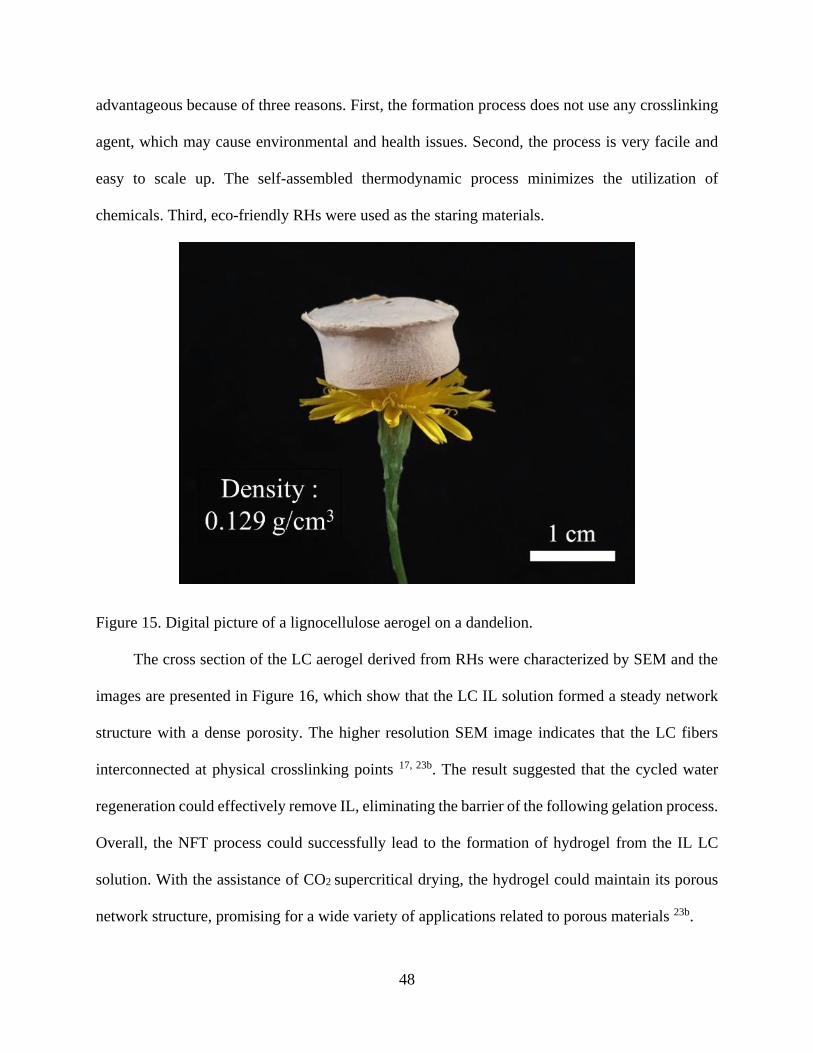
48
advantageous because of three reasons. First, the formation process does not use any crosslinking
agent, which may cause environmental and health issues. Second, the process is very facile and
easy to scale up. The self-assembled thermodynamic process minimizes the utilization of
chemicals. Third, eco-friendly RHs were used as the staring materials.
Figure 15. Digital picture of a lignocellulose aerogel on a dandelion.
The cross section of the LC aerogel derived from RHs were characterized by SEM and the
images are presented in Figure 16, which show that the LC IL solution formed a steady network
structure with a dense porosity. The higher resolution SEM image indicates that the LC fibers
interconnected at physical crosslinking points 17, 23b. The result suggested that the cycled water
regeneration could effectively remove IL, eliminating the barrier of the following gelation process.
Overall, the NFT process could successfully lead to the formation of hydrogel from the IL LC
solution. With the assistance of CO2 supercritical drying, the hydrogel could maintain its porous
network structure, promising for a wide variety of applications related to porous materials 23b.
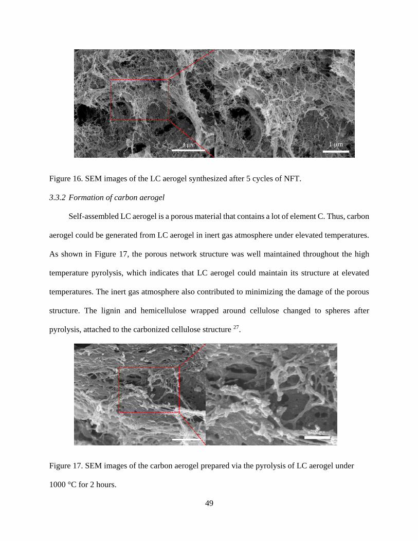
49
Figure 16. SEM images of the LC aerogel synthesized after 5 cycles of NFT.
3.3.2 Formation of carbon aerogel
Self-assembled LC aerogel is a porous material that contains a lot of element C. Thus, carbon
aerogel could be generated from LC aerogel in inert gas atmosphere under elevated temperatures.
As shown in Figure 17, the porous network structure was well maintained throughout the high
temperature pyrolysis, which indicates that LC aerogel could maintain its structure at elevated
temperatures. The inert gas atmosphere also contributed to minimizing the damage of the porous
structure. The lignin and hemicellulose wrapped around cellulose changed to spheres after
pyrolysis, attached to the carbonized cellulose structure 27.
Figure 17. SEM images of the carbon aerogel prepared via the pyrolysis of LC aerogel under
1000 °C for 2 hours.

50
Figure 18 shows the XRD patterns of the LC aerogel, RH cellulose, and carbon aerogels.
The results show that RH cellulose bears the typical cellulose I structure according to the
characteristic peaks (002), (101), and (040) at 15.5°, 22.1°, and 34.7°, respectively 28. The LC
aerogel was obtained after water regeneration and CO2 supercritical drying. It mainly showed one
broad hump at ca. 21.1°, which indicates that the regenerated LC has a lower level of crystallinity
than the raw cellulose, which is expected 29. According to the previous reports 30, the regenerated
cellulose or lignocellulose possess a cellulose II structure with a characteristic peak (002) at 12.1°,
which is also shown in the XRD pattern of LC aerogel. The lowered crystallinity of the regenerated
LC is because some of the intrinsic inter- and intra-molecular hydrogen bonds and crystallized
structures of cellulose was destroyed in the dissolving process 29. However, the intensity of peak
(002) of the LC aerogel is relatively low as shown in Figure 5a. This is likely due to the fact that
lignin restrained the swelling of cellulose molecules in IL and limited the solubility of cellulose
molecules at relatively low temperatures (85 °C) 23b, 30b, 31.

51
Figure 18. XRD patterns of the LC aerogel and the cellulose derived from RHs
3.3.3 Porosity properties and surface areas of the LC aerogel and carbon aerogels
As shown in Figure 19, the N2 adsorption-desorption curves of the LC aerogel and carbon
aerogel prepared at 1000 °C are of type IV, suggesting that the two types of aerogels are
mesoporous. The curves also indicate that the LC aerogel formed a mesoporous network structure
after cycled NFT thermodynamic crosslinking, and the carbon aerogel maintained a porous
structure after pyrolysis. Based on the isotherms, the specific surface area (SSA) and pore property
data were calculated and are summarized in Table 3. The LC aerogel derived from RHs has a
relatively higher total specific surface area (SSA (total)) of 106.5 m2/g, compared to the literature
data of 80.7 m2/g 17. The main reason is probably because RHs contain a high cellulose content 32,
which could minimize the effect of lignin in the solution and assist the formation of a porous
10 15 20 25 30 35 40 45 50
(040)
(101)
(002)
(101)
LC aerogel
Rel
ativ
e In
tensi
ty (
a.u.)
2-Theta (degrees)
RH-cellulose
(002)
(a)

52
network structure. The LC aerogel also has a high SSA (meso)/SSA (total) ratio, which is probably
owing to the low surface tension at the supercritical CO2/hydrogel interface during CO2
supercritical drying. After the conversion of LC aerogel to carbon aerogel, the SSA (total) of the
carbon aerogel sample increased from 106.5 to 217.3 m2/g after pyrolysis.
Figure 19. N2 adsorption-desorption isotherms of the LC aerogel and carbon aerogel.
Table 3. Surface area of the LC aerogel and carbon aerogel.
Sample
SSA(total)
[m2/g]
SSA(meso)
[m2/g]
SSA(micro)
[m2/g]
SSA(meso) /SSA(total)
[%]
SSA(micro) /SSA(total)
[%]
LC aerogel 106.5 100.2 6.2 94.1 5.8
Carbon aerogel 217.3 55.5 143.6 25.5 66.1
3.3.4 Hydrophobicity and Oil Spill Applications
LC is hydrophilic due to the hydroxyl groups present on the structures of lignin, cellulose,
and hemicellulose. It was reported that a hydrophobic coating could be applied on a recycled
0.0 0.2 0.4 0.6 0.8 1.00
2
4
6
8
Vo
lum
e A
dso
rbed
(cm
3/g
)
Relative Pressure (P/P0)
Carbon aerogel-1000-200
Lignocellulose aerogel

53
cellulose aerogel to make it oleophilic 21. One of the main incentives to convert cellulose aerogels
to be hydrophobic is because hydrophobic aerogels can repel water and attract oil, making them
promising for applications such as oil spill cleaning 33. Figure 20 shows the water contact angle
(WCA) of 132.5° and 130.5° on an external and a freshly cut surface of the coated LC aerogel,
respectively. This result suggests that the hydrophobic modification can reach deep into the LC
aerogel, and the entire 3-D porous structure was converted to be hydrophobic.
Figure 20. Water contact angle of the MTMS treated LC aerogel: (a) on an external surface, and
(b) on a freshly cut surface.
In order to investigate the potential oil absorption performance of the surface-modified LC
aerogel, pump oil, which was stained by Sudan III dye to show a higher visibility, was adopted for
the demonstration, and the results are briefly presented in Figure 21. The surface modified LC
aerogel can easily absorb the pump oil. At the beginning of the test, the stained pump oil was
floating on water surface. Upon direct contact with the aerogel, the oil was quickly absorbed. After
the completion of the absorption, the oil was completely removed and no stained oil was visibly
detected on the water face. These results suggest that the modified LC aerogel could effectively
absorb oil from water surface, offering an environmentally-friendly alternative option for oil spill
cleaning.

54
Figure 21. Pump oil absorption process by treated LC aerogel.
3.3.5 Silica nanoparticles from IL-RH residue
IL-RH residue was rinsed by DI water and dried in an oven. After it was dried, the residue
was calcined at 700 °C for 2 hours. The XRD patterns shown in Figure 22 indicate that the silica
derived from IL-RH residue remained to be amorphous. It exhibits a similar XRD pattern as the
silica derived from HCl treated RHs (RH-HCl-silica) 9. However, using the IL-RH residue to make
silica contributes to the RH biomass comprehensive application strategy, which will improve the
utilization efficiency of RHs and broaden the application of RH biomass 9.
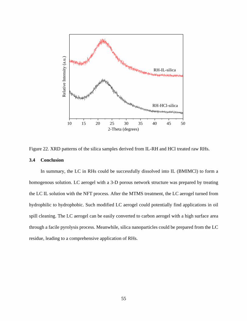
55
Figure 22. XRD patterns of the silica samples derived from IL-RH and HCl treated raw RHs.
3.4 Conclusion
In summary, the LC in RHs could be successfully dissolved into IL (BMIMCl) to form a
homogenous solution. LC aerogel with a 3-D porous network structure was prepared by treating
the LC IL solution with the NFT process. After the MTMS treatment, the LC aerogel turned from
hydrophilic to hydrophobic. Such modified LC aerogel could potentially find applications in oil
spill cleaning. The LC aerogel can be easily converted to carbon aerogel with a high surface area
through a facile pyrolysis process. Meanwhile, silica nanoparticles could be prepared from the LC
residue, leading to a comprehensive application of RHs.
10 15 20 25 30 35 40 45 50
RH-IL-silica
RH-HCl-silica
Rel
ativ
e In
ten
sity
(a.
u.)
2-Theta (degrees)

56
References
1. Wang, Z.; Yu, J.; Zhang, X.; Li, N.; Liu, B.; Li, Y.; Wang, Y.; Wang, W.; Li, Y.; Zhang,
L.; Dissanayake, S.; Suib, S. L.; Sun, L., Large-Scale and Controllable Synthesis of Graphene
Quantum Dots from Rice Husk Biomass: A Comprehensive Utilization Strategy. ACS Applied
Materials & Interfaces 2016, 8 (2), 1434-1439.
2. Krishnarao, R.; Godkhindi, M., Distribution of silica in rice husks and its effect on the
formation of silicon carbide. Ceramics international 1992, 18 (4), 243-249.
3. Rahman, I.; Riley, F., The control of morphology in silicon nitride powder prepared from
rice husk. Journal of the European Ceramic Society 1989, 5 (1), 11-22.
4. Seo, E.; Andreoli, M.; Chiba, R., Silicon tetrachloride production by chlorination method
using rice husk as raw material. Journal of materials processing technology 2003, 141 (3), 351-
356.
5. Wang, W.; Martin, J. C.; Huang, R.; Huang, W.; Liu, A.; Han, A.; Sun, L., Synthesis of
silicon complexes from rice husk derived silica nanoparticles. RSC Advances 2012, 2 (24), 9036-
9041.
6. Sun, L.; Gong, K., Silicon-based materials from rice husks and their applications.
Industrial & engineering chemistry research 2001, 40 (25), 5861-5877.
7. Wang, Z.; Chen, H.; Xu, L.; Xu, S. Q.; Gao, C. F.; Oliphant, A. J.; Liu, J.; Lu, Y.; Wang,
W.; Sun, L., Synthesis and colour prediction of stable pigments from rice husk biomass. Green
Materials 2015, 3 (1), 10-14.
8. Li, Y.; Lan, J. Y.; Liu, J.; Yu, J.; Luo, Z.; Wang, W.; Sun, L., Synthesis of Gold
Nanoparticles on Rice Husk Silica for Catalysis Applications. Industrial & engineering chemistry
research 2015, 54 (21), 5656-5663.
9. Chen, H.; Wang, W.; Martin, J. C.; Oliphant, A. J.; Doerr, P. A.; Xu, J. F.; DeBorn, K. M.;
Chen, C.; Sun, L., Extraction of lignocellulose and synthesis of porous silica nanoparticles from
rice husks: a comprehensive utilization of rice husk biomass. ACS Sustainable Chemistry &
Engineering 2012, 1 (2), 254-259.
10. Saha, B. C. In Lignocellulose biodegradation and applications in biotechnology, ACS
symposium series, Washington, DC; American Chemical Society; 1999: 2004; pp 2-35.
11. Yang, Q.; Fukuzumi, H.; Saito, T.; Isogai, A.; Zhang, L., Transparent cellulose films with
high gas barrier properties fabricated from aqueous alkali/urea solutions. Biomacromolecules 2011,
12 (7), 2766-2771.
12. Poplin, J. H.; Swatloski, R. P.; Holbrey, J. D.; Spear, S. K.; Metlen, A.; Grätzel, M.;
Nazeeruddin, M. K.; Rogers, R. D., Sensor technologies based on a cellulose supported platform.
Chemical communications 2007, (20), 2025-2027.
13. Cai, J.; Kimura, S.; Wada, M.; Kuga, S.; Zhang, L., Cellulose aerogels from aqueous alkali
hydroxide–urea solution. ChemSusChem 2008, 1 (1‐2), 149-154.
14. Ludueña, L.; Fasce, D.; Alvarez, V. A.; Stefani, P. M., Nanocellulose from rice husk
following alkaline treatment to remove silica. BioResources 2011, 6 (2), 1440-1453.
15. (a) Lee, S. H.; Doherty, T. V.; Linhardt, R. J.; Dordick, J. S., Ionic liquid‐mediated selective
extraction of lignin from wood leading to enhanced enzymatic cellulose hydrolysis. Biotechnology
and Bioengineering 2009, 102 (5), 1368-1376; (b) Zhu, S.; Wu, Y.; Chen, Q.; Yu, Z.; Wang, C.;
Jin, S.; Ding, Y.; Wu, G., Dissolution of cellulose with ionic liquids and its application: a mini-
review. Green Chemistry 2006, 8 (4), 325-327.

57
16. Swatloski, R. P.; Spear, S. K.; Holbrey, J. D.; Rogers, R. D., Dissolution of cellose with
ionic liquids. Journal of the American Chemical Society 2002, 124 (18), 4974-4975.
17. Li, J.; Lu, Y.; Yang, D.; Sun, Q.; Liu, Y.; Zhao, H., Lignocellulose aerogel from wood-
ionic liquid solution (1-allyl-3-methylimidazolium chloride) under freezing and thawing
conditions. Biomacromolecules 2011, 12 (5), 1860-1867.
18. Wu, Z.-S.; Yang, S.; Sun, Y.; Parvez, K.; Feng, X.; Mullen, K., 3D nitrogen-doped
graphene aerogel-supported Fe3O4 nanoparticles as efficient electrocatalysts for the oxygen
reduction reaction. Journal of the American Chemical Society 2012, 134 (22), 9082-9085.
19. Aliev, A. E.; Oh, J.; Kozlov, M. E.; Kuznetsov, A. A.; Fang, S.; Fonseca, A. F.; Ovalle, R.;
Lima, M. D.; Haque, M. H.; Gartstein, Y. N., Giant-stroke, superelastic carbon nanotube aerogel
muscles. science 2009, 323 (5921), 1575-1578.
20. Hu, Y.; Tong, X.; Zhuo, H.; Zhong, L.; Peng, X.; Wang, S.; Sun, R., 3D hierarchical porous
N-doped carbon aerogel from renewable cellulose: an attractive carbon for high-performance
supercapacitor electrodes and CO 2 adsorption. RSC Advances 2016, 6 (19), 15788-15795.
21. Nguyen, S. T.; Feng, J.; Le, N. T.; Le, A. T.; Hoang, N.; Tan, V. B.; Duong, H. M.,
Cellulose aerogel from paper waste for crude oil spill cleaning. Industrial & engineering chemistry
research 2013, 52 (51), 18386-18391.
22. (a) Bi, H.; Yin, Z.; Cao, X.; Xie, X.; Tan, C.; Huang, X.; Chen, B.; Chen, F.; Yang, Q.; Bu,
X., Carbon fiber aerogel made from raw cotton: a novel, efficient and recyclable sorbent for oils
and organic solvents. Advanced Materials 2013, 25 (41), 5916-5921; (b) Wu, Z. Y.; Li, C.; Liang,
H. W.; Chen, J. F.; Yu, S. H., Ultralight, flexible, and fire‐resistant carbon nanofiber aerogels from
bacterial cellulose. Angewandte Chemie 2013, 125 (10), 2997-3001.
23. (a) Ding, B.; Cai, J.; Huang, J.; Zhang, L.; Chen, Y.; Shi, X.; Du, Y.; Kuga, S., Facile
preparation of robust and biocompatible chitin aerogels. Journal of Materials Chemistry 2012, 22
(12), 5801-5809; (b) Lu, Y.; Sun, Q.; Yang, D.; She, X.; Yao, X.; Zhu, G.; Liu, Y.; Zhao, H.; Li,
J., Fabrication of mesoporous lignocellulose aerogels from wood via cyclic liquid nitrogen
freezing–thawing in ionic liquid solution. Journal of Materials Chemistry 2012, 22 (27), 13548-
13557.
24. (a) Li, J.; Wang, X.; Huang, Q.; Gamboa, S.; Sebastian, P., Studies on preparation and
performances of carbon aerogel electrodes for the application of supercapacitor. Journal of Power
Sources 2006, 158 (1), 784-788; (b) Miller, J.; Dunn, B.; Tran, T.; Pekala, R., Deposition of
ruthenium nanoparticles on carbon aerogels for high energy density supercapacitor electrodes.
Journal of the Electrochemical Society 1997, 144 (12), L309-L311; (c) Chien, H. C.; Cheng, W.
Y.; Wang, Y. H.; Lu, S. Y., Ultrahigh specific capacitances for supercapacitors achieved by nickel
cobaltite/carbon aerogel composites. Advanced Functional Materials 2012, 22 (23), 5038-5043.
25. (a) Moreno-Castilla, C.; Maldonado-Hódar, F., Carbon aerogels for catalysis applications:
An overview. Carbon 2005, 43 (3), 455-465; (b) Biener, J.; Stadermann, M.; Suss, M.; Worsley,
M. A.; Biener, M. M.; Rose, K. A.; Baumann, T. F., Advanced carbon aerogels for energy
applications. Energy & Environmental Science 2011, 4 (3), 656-667.
26. de Carvalho Mendes, C. A.; Ferreira, N. M. S.; Furtado, C. R. G.; de Sousa, A. M. F.,
Isolation and characterization of nanocrystalline cellulose from corn husk. Materials Letters 2015,
148, 26-29.
27. Xu, X.; Zhou, J.; Nagaraju, D. H.; Jiang, L.; Marinov, V. R.; Lubineau, G.; Alshareef, H.
N.; Oh, M., Flexible, Highly Graphitized Carbon Aerogels Based on Bacterial Cellulose/Lignin:
Catalyst‐Free Synthesis and its Application in Energy Storage Devices. Advanced Functional
Materials 2015, 25 (21), 3193-3202.

58
28. Kalita, E.; Nath, B.; Deb, P.; Agan, F.; Islam, M. R.; Saikia, K., High quality fluorescent
cellulose nanofibers from endemic rice husk: Isolation and characterization. Carbohydrate
polymers 2015, 122, 308-313.
29. Sun, X.; Chi, Y.; Mu, T., Studies on staged precipitation of cellulose from an ionic liquid
by compressed carbon dioxide. Green Chemistry 2014, 16 (5), 2736-2744.
30. (a) Tang, S.; Baker, G. A.; Ravula, S.; Jones, J. E.; Zhao, H., PEG-functionalized ionic
liquids for cellulose dissolution and saccharification. Green Chemistry 2012, 14 (10), 2922-2932;
(b) Cheng, G.; Varanasi, P.; Li, C.; Liu, H.; Melnichenko, Y. B.; Simmons, B. A.; Kent, M. S.;
Singh, S., Transition of cellulose crystalline structure and surface morphology of biomass as a
function of ionic liquid pretreatment and its relation to enzymatic hydrolysis. Biomacromolecules
2011, 12 (4), 933-941.
31. Li, W.; Sun, N.; Stoner, B.; Jiang, X.; Lu, X.; Rogers, R. D., Rapid dissolution of
lignocellulosic biomass in ionic liquids using temperatures above the glass transition of lignin.
Green Chemistry 2011, 13 (8), 2038-2047.
32. Gani, A.; Naruse, I., Effect of cellulose and lignin content on pyrolysis and combustion
characteristics for several types of biomass. Renewable Energy 2007, 32 (4), 649-661.
33. Xiao, S.; Gao, R.; Lu, Y.; Li, J.; Sun, Q., Fabrication and characterization of nanofibrillated
cellulose and its aerogels from natural pine needles. Carbohydrate polymers 2015, 119, 202-209.

59
Chapter 4. Summary and Outlook
4.1 Summary
Rice Husks (RHs) are one of the most available and abundant biomasses in the world, and
could be consider as a “true” biomass as they are the byproduct after rice milling. They have been
applied in many different fields including chemistry, biology, materials science, and
environmental protection. However, during most conventional utilizations of RHs, researchers
focus on one component of RHs (such as silica) while ignore others. Achieve a comprehensive
utilization of RHs and generating product diversity should be the goal for the future research in
this field. In this thesis, two main components of RH biomass were extracted: silica and
lignocellulose. A calcination method was adopted to prepare silica from RHs. The synthesized
silica nanoparticles could be used for the synthesis of green phosphor Zn2SiO4:Mn2+ because of its
high reactivity. This study also experimented with and discussed the effects of reaction
temperature and doping concentration of Mn2+ on the photoluminescence performance of the
synthesized phosphors. Compared with the phosphors synthesized from commercial silica, this
plant-sourced phosphor is a promising alternative because of its low price and better
photoluminescence properties. For the second part of this study, lignocellulose was extracted by
using ionic liquid (BMIMCL). Highly light and porous lignocellulose aerogel was synthesized via
a freeze-thaw process, water regeneration, and CO2 supercritical drying. After surface modification,
the lignocellulose aerogel exhibited highly hydrophobic property, making it effective in oil spill
adsorption. In addition, carbon aerogel was prepared when the lignocellulose aerogel was
pyrolyzed at high temperatures under an inert gas atmosphere, which can potentially be used for
supercapacitors. Following the comprehensive application strategy, the RH residue was utilized to
prepare high purity amorphous silica, which can be used to make various silica derived chemicals,

60
such as silicate phosphors. This project explored the comprehensive utilization of RH biomass by
producing two major products for various applications.
4.2 Outlook
While this project and most current research in this field focus on deriving various valuable
products from RHs for practical applications, how to better tailor the morphology of the basic
products should be another major focus for future research. Although amorphous silica
nanoparticles with a high surface area has been synthesized from RHs, they form clusters and thus
not well separated with each other, thus cannot be well dispersed to form a stable dispersion. This
defect is the major barrier that limits RH-silica for many more advanced applications, such as silica
based core-shell structured catalysts and biomedical applications. For the lignocellulose from RHs,
many new applications can be explored if the morphology of the lignocellulose can be better
tailored. For example, cellulose nanocrystals can possibly be derived from RHs, which have
promising applications in composites.