Compound Cycle Engine Program - NASA CYCLE ENGINE PROGRAM M I W G.A. Bobula Propulslon Directorate...
23
NASA Technical Memorandum 88879 USAAVSCOM Technical Report 86-C-37 Compound Cycle Engine Program lMASB-TB-88879) CCflPCUNI) CYCLE ENGINE N87-I 17’30 PEOGHAei {NASA) 23 p CSCL 21E Unclas G3/07 44804 G.A. Bobula Propulsion Directorate U. S. Army Aviation Research and Technology Activity-A VSCOM Lewis Research Center Cleveland, Ohio W. T . Wintucky Lewis Research Center Cleveland, Ohio and J.G. Castor Garrett Turbine Engine Company Phoenix, Arizona Prepared for the Rotary Wing Propulsion System Specialist Meeting sponsored by the American Helicopter Society Williamsburg, Virginia, November 12- 14, 1986 https://ntrs.nasa.gov/search.jsp?R=19870002357 2018-05-22T23:42:07+00:00Z
Transcript of Compound Cycle Engine Program - NASA CYCLE ENGINE PROGRAM M I W G.A. Bobula Propulslon Directorate...

NASA Technical Memorandum 88879
USAAVSCOM Technical Report 86-C-37
Compound Cycle Engine Program lMASB-TB-88879) C C f l P C U N I ) C Y C L E E N G I N E N87-I 17’30
PEOGHAei { N A S A ) 2 3 p CSCL 21E
U n c l a s G3/07 44804
G.A. Bobula Propulsion Directorate U. S. Army Aviation Research and Technology Activity-A VSCOM Lewis Research Center Cleveland, Ohio
W. T . Wintucky Lewis Research Center Cleveland, Ohio
and
J.G. Castor Garrett Turbine Engine Company Phoenix, Arizona
Prepared for the Rotary Wing Propulsion System Specialist Meeting sponsored by the American Helicopter Society Williamsburg, Virginia, November 12- 14, 1986
https://ntrs.nasa.gov/search.jsp?R=19870002357 2018-05-22T23:42:07+00:00Z

COMPOUND CYCLE ENGINE PROGRAM
M I
W
G.A. Bobula Propuls lon D i r e c t o r a t e
Leu1 s Research Center Cleveland, Ohio 44135
U.S. Army A v i a t i o n Research and Technology A c t i v i t y - AVSCOM
W. T. W i n tuc ky N a t i o n a l Aeronautics and Space A d m i n i s t r a t i o n
Lewi s Research Center Cleveland, Ohio 44135
and
3 . 6 . Castor G a r r e t t Turbine Engine Company
Phoenix, Ar izona 85010
SUMMARY
The Compound Cycle Engine (CCE) i s a h i g h l y turbocharged, power compounded ower p l a n t which combines the l i g h t w e i g h t pressure r i s e c a p a b i l i t y o f a gas t u r b i n e w i t h t h e h i g h ' e f f i c i e n c y o f a d i e s e l . c r a f t , t h e CCE w i l l reduce f u e l burned f o r a t y p i c a l 2 hr ( p l u s 30 min reserve) miss ion by 30 t o 40 percent when compared t o a convent ional advanced technology gas t u r b i n e . .The CCE can prov ide a 50 percent Increase i n range-payload pro- duc t on t h i s miss ion.
When opt imized f o r a r o t o r -
A program t o e s t a b l i s h the technology base f o r a Compound Cycle Engine i s presented. The goal o f t h i s program i s t o research and develop those technol - ogies which a r e b a r r i e r s t o demonstrat ing a m u l t i c y l i n d e r d i e s e l core i n t h e e a r l y 1990's. The major a c t i v i t y underway i s a three-phased c o n t r a c t w i t h t h e G a r r e t t Turbine Engine Company t o perform: ( 1 ) d l i g h t h e l i c o p t e r f e a s i b i l i t y study, ( 2 ) component technology development, and (3 ) l u b r i c a n t and m a t e r i a l research and development. Other r e l a t e d a c t i v i t i e s a r e a l s o presented.
INTRODUCTION
A program i s be ing conducted t o e s t a b l i s h t h e technology base f o r a com- pound c y c l e engine (CCE). The program goal i s t o develop those technologies which a r e b a r r i e r s t o demonstrat ing a m u l t i c y l i n d e r gas generator, o r core engine, d u r i n g t h e e a r l y 1990's. t h r e e phase c o n t r a c t u a l e f f o r t being conducted by t h e G a r r e t t Turbine Engine Company, under t h e sponsorship of the U.S. Army A v i a t i o n Systems Command: t h e f i r s t phase i s an a n a l y t i c a l f e a s i b i l i t y study o f a compound c y c l e engine f o r a l i g h t h e l i c o p t e r a p p l i c a t i o n ; t he second i s a component technology develop- ment program; and the t h i r d i s a l u b r i c a n t and m a t e r i a l s research and develop- ment program. t o accomplish t h e 1990's demonstrat ion o f a m u l t i c y l i n d e r d i e s e l core.
A m a j o r p a r t o f t h e technology program i s a
Other r e l a t e d program elements a r e a l s o underway i n an e f f o r t

Recent s tud ies have shown t h a t f u e l i s 70 percent o f t h e tonnage shipped by t h e Army f o r supply and support under b a t t l e f i e l d cond i t i ons . study, re ference 1, showed t h a t a compound c y c l e engine, w i t h i t s super io r f u e l e f f i c i e n c y , when i n s t a l l e d i n a Blackhawk h e l i c o p t e r and operated over a t y p i c a l 2-hr mission, cou ld have a s p e c i f i c weight as h igh as 0.76 pounds per horsepower ( lb /hp) and s t i l l be compet i t i ve w i t h a gas t u r b i n e engine i n terms o f range-payload product . Th is r e s u l t assumed the same take -o f f gross weight , and balanced t h e CCE's increased engine weight aga ins t i t s lower f u e l consumed p l u s tankage weight.
Another
This paper summarizes t h e s ta tus o f t h e cu r ren t C C E a c t i v i t i e s . The f e a s i b i l i t y study p red ic ted t h a t t h e 1000 horsepower (hp) h e l i c o p t e r engine would have a s p e c i f j c weight of 0.432 lb /hp and a s p e c i f i c f u e l consumption (SFC) o f 0.33 pounds per horsepower-hour ( lb /hp-hr ) . c y l i n d e r component development program and o f t h e l u b r i c a n t / m a t e r i a l s research w i l l a l s o be presented. The paper w i l l conclude w i t h . o t h e r r e l a t e d a c t i v i t i e s ou ts ide t h e scope of t h e i n i t i a l three-phase con t rac t . A l l these elements taken together comprise the long range p lan t o meet t h e 1990's d i e s e l core, mu l t i cy4 inde r demonstrat ion date.
The s t a t e o f t h e s i n g l e
BACKGROUND
A compound cyc le engine, shown schemat ica l ly I n f i g u r e 1, combines the a i r f l o w capac i t y and ' l i gh t -we igh t pressure r i s e fea tures o f a gas t u r b i n e w i t h t h e h i g h l y e f f i c i e n t , a l though heavier , d i e s e l . The compressor o f t he tu rbo- machinery module d e l i v e r s a h i g h l y pressur ized charge o f a i r t o t h e d i e s e l c y l i n d e r s . Wi th in t h e cy l i nde rs , f u r t h e r compression, f u e l i n j e c t i o n , combus- t i o n , and expansion takes place, as i n any convent ional r e c i p r o c a t i n g engine, b u t a t s u b s t a n t i a l l y h igher pressures and temperatures. Power i s ex t rac ted du r ing t h e expansion s t roke and t h e exhaust gases are then re tu rned t o t h e turbomachinery module. The exhaust energy a v a i l a b l e i s i n excess o f what i s r equ i red t o d r i v e t h e compressor, and t h a t excess power i s ex t rac ted i n a f r e e t u r b i n e and combined w i t h t h e d i e s e l ou tpu t through a gear t r a i n . Th is com- b ined ou tpu t comprises t h e t o t a l c y c l e output , hence t h e name compound c y c l e engine.
A s o u t l i n e d i n re ference 2, t h e 1940's and e a r l y 1950's saw cons iderab le i n t e r e s t i n compound c y c l e engines being app l i ed t o a i r c r a f t . 1950's, t h e most f u e l e f f i c i e n t i n t e r n a l combustion engine ever f lown, the Napier Nomad, demonstrated an SFC o f less than 0.35 lb/hp-hr i n f l i g h t , re fe rence 3. The engine used a h i g h l y turbocharged, power compounded c y c l e t o reach t h i s l e v e l o f performance. 3580 l b . The advent o f t h e gas tu rb ine , however, coupled w i t h t h e low cos t o f f u e l a t t h e t ime and t h e d r i v e toward f a s t e r speeds, brought an end t o the Nomad. This technology stagnated w h i l e gas tu rb ines f l o u r i s h e d i n t h e 30-plus i n t e r v e n i n g years.
The Army/NASA S m a l l Engine Technology program, re fe rence 4 i n d i c a t e d t h a t performance increases o f s i g n i f i c a n t magnitude f o r t he year 2000 turbomachine w i l l r e q u i r e improved cyc les i n c o r p o r a t i n g the r e s u l t s o f i n t e n s i v e research and development e f f o r t s , main ly i n ma te r ia l s , t h a t i s ceramics, and secondly i n component aerodynamic design. E f f o r t s i n o ther areas w i l l p rov ide payo f f s
Dur ing t h e e a r l y
I t de l i ve red 3050 hp ou tpu t a t a weight o f
2

o f a smal ler magnitude. The reduct ion i n f u e l burned p r e d i c t e d f o r t h e year 2000 r o t o r c r a f t a p p l i c a t i o n was dependent on a l l t h e key technologies reaching t h e a p p l i c a t i o n s phase, references 5 and 6.
Economic and l o g i s t i c pressures have fo rced us t o reconsider more e f f i - c i e n t power p l a n t s such as t h e compound cyc le . The a l ready mentioned tonnage which t h e Army must supply and support under b a t t l e f i e l d cond i t i ons , and t h e need f o r a deep p e n e t r a t i o n c a p a b i l i t y , a r e examples o f t h e d r i v e r s toward b e t t e r f u e l e f f i c i e n c y . It i s est imated t h a t by adapt ing t h e Napier Nomad t o a h e l l c o p t e r m iss ion and inco rpo ra t i ng modern technologies I n t o i t s 35 year o l d design, t h i s compound c y c l e engine could be made t o run a t an SFC i n t h e range o f 0.35 lb/hp-hr and weigh 0.6 lb/hp o r l ess . accomplished by removing t h e reduct ion gearbox which had been needed f o r a p r o p e l l e r d r i v e ; d e l e t i n g t h e variable-speed transmission, which had been needed f o r turbomachinery and d iese l speed matching, and i n s t e a d i n c o r p o r a t i n g a f r e e t u r b i n e stage f o r power ex t rac t i on ; reducing t h e number o f t u rbo - machinery stages s u b s t a n t i a l l y f r o m t h e o r i g i n a l Nomad design; and then by u t i l i z i n g modern m a t e r i a l s and s t r u c t u r a l ana lys i s techniques.
U n t i l r e c e n t l y , few major advances have occurred i n r e c i p r o c a t i n g engines. I n 1977, however, a j o i n t Defense Advanced Research P r o j e c t Agency (DARPA), A i r Force, and G a r r e t t program, reference 7, i n v e s t i g a t e d a h i g h l y turbocharged, power compounded tu rbo fan /d iese l engine f o r a c r u i s e m i s s i l e a p p l i c a t i o n . Power d e n s l t i e s g r e a t e r than seven times t h a t o f t h e bes t c u r r e n t p roduc t i on d i e s e l s were demonstrhted i n a s ing le c y l i n d e r r i g . A m iss ion r e d i r e c t i o n termlnated t h a t e f f o r t , however, t ha t program formed t h e bas i s f o r t h e present a c t 1 v i t y .
The weight r e d u c t i o n would be
COMPOUND CYCLE ENGINE PROGRAY
The long t e r m goal o f t h e compound c y c l e engine program i s a 30 t o 40 percent r e d u c t i o n i n m i s s i o n f u e l weight w i t h a r e s u l t a n t 50 percent improvement i n payload-range product f o r a l i g h t h e l i c o p t e r . t h e s p e c i f i c o b j e c t i v e i s t o a t t a c k t h e h i g h r i s k , b a r r i e r technologies i n p r e p a r a t i o n f o r a r n u l t i c y l i n d e r core demonstrator program i n t h e e a r l y 1990's. Toward t h i s end, t h r e e p a r a l l e l phased con t rac tua l e f f o r t s w i t h t h e G a r r e t t Turb ine Engine Company a r e underway. I n t h e f i r s t phase, a f e a s i b l l l t y study was conducted t o determine t h e m e r i t o f us ing a compound c y c l e engine i n a l i g h t h e l i c o p t e r . I n t h e second phase, component research i s be ing conducted on a s i n g l e c y l i n d e r t e s t r i g . Lubr icant and m a t e r i a l research i s be ing con- ducted i n phase th ree .
I n t h e near t e r m ,
Phase I : L i g h t R o t o r c r a f t F e a s i b i l i t y Study
F igu re 2 d e p i c t s t h e numerous opt ions whlch were considered i n t h e engine f e a s i b i l i t y study. I t should be noted t h a t t h e engine looks very s i m i l a r t o a normal t u rbosha f t c o n f i g u r a t i o n , but w i t h t h e combustor replaced by a power producing d i e s e l core. The turbomachinery maps were e s s e n t i a l l y l i f t e d f rom e x i s t i n g t u r b i n e engines, w i t h t h e study e f f o r t p r i m a r i l y r e v o l v l n g around t h e d i e s e l core c o n f i g u r a t i o n .
3

The study options include: 2-stroke versus 4-stroke cycle, compressor discharge aftercooling, scavenging method (loop versus uniflow versus 4-stroke), turbocompounding versus turbocharging, method of compounding, and cylinder geometry. The engine design point conditions were also considered options. Figure 3 presents a summary plot of BSFC and weight trends as they were affected by scavenging option, and by turbocompounding versus turbo- charging option. Turbocompounding was chosen due to its substantially lower engine weight and fuel burned. power strokes as a 4-stroke, provide a lighter power plant than the 4-stroke cycle. To achieve the lowest possible predicted weight, a uniflow scavenged design was chosen. Finally, for more stable off-design operation, a one-and- one-half spool turbocompounding scheme was selected. The half spool refers to the use of a mechanically disconnected, or free, power turbine.
point SFC penalty was predicted with aftercooling, due to pressure losses and power extracted for a blower. reduction in cylinder inlet temperature of 300 O F at maximum power, which should result in a significant improvement in life. The weight added due to the aftercooler was balanced by a cylinder size and weight reduction, since the cooler, more dense intake air charge now required less displaced volume for the same mass flow.
The 2-stroke cycle, with two times as many
The decision on aftercooling was driven by life considerations. A two
However, an effectiveness of 0.4 produced a
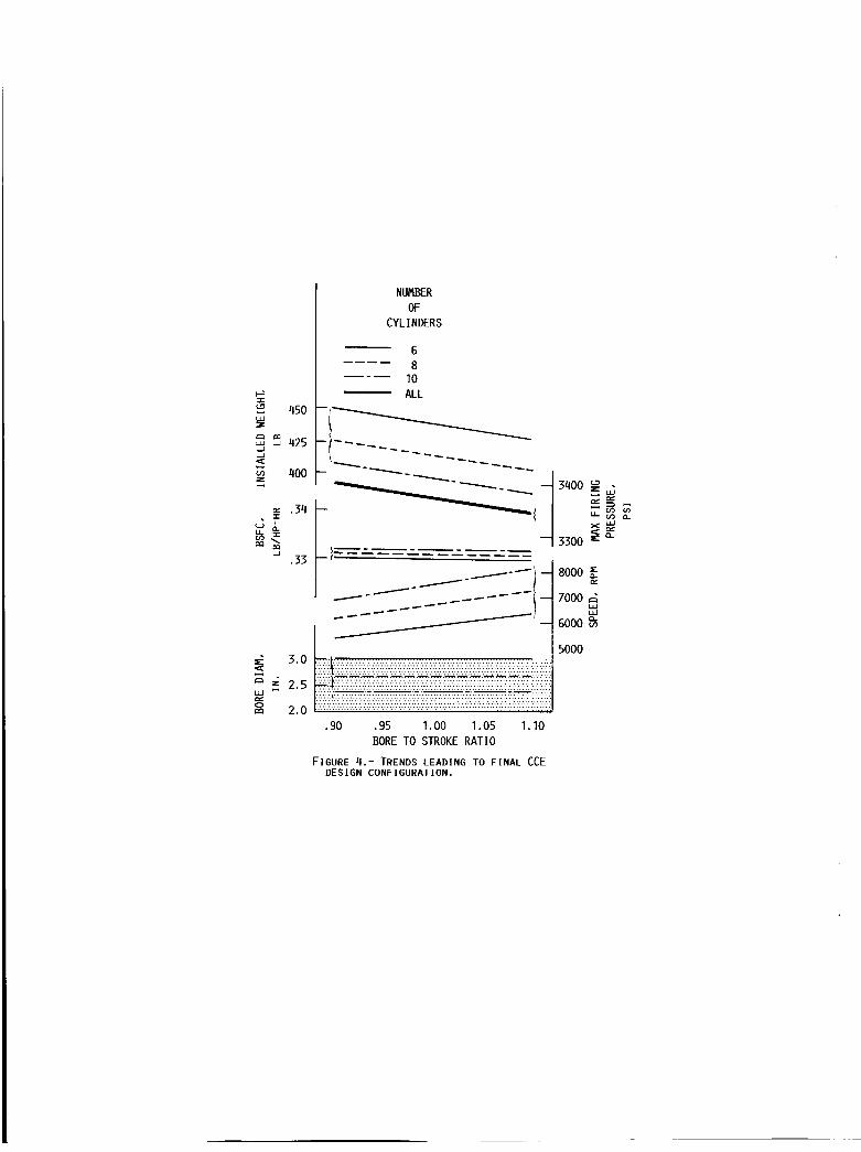
The trends which led to the final design are shown in figure 4. These plots assumed that fdr the life goal of the helicopter CCE, a mean piston speed of 3000 ft/min should not be exceeded. Having previously selected a uniflow scavenged cylinder, a minimum bore size of 3.0 in. was required to allow room for exhaust valves and an injector, and this drove the design to six cylinders.
eight or ten cylinders, however, the weight was somewhat reduced by selecting an over-square bore to stroke ratio of 1.05 to reduce cylinder height. As life and wear are the major concerns in this engine, the selection of the six cylinder design dld allow a substantially lower engine speed than either the eight or the ten. SFC was nearly independent of both bore to stroke ratio and numbers of cylinders, and although the maximum firing pressure is independent of the’number of cylinders, the pressure was slightly reduced by choosing the 1.05 bore to stroke ratio. Thus, the final design configuration, presented in table I, is seen to be a trade among life, performance, and weight considera- tions. A schematic of the final design is presented in figure 5.
I The six cylinder configuration accepted a small weight penalty compared to
A simple analysis, using figures 6 to 8, may be performed to examine the benefits of a compound cycle. In figure 6, a composite mission profile is presented for comparison purposes. It can be seen that 80 percent of the mission is spent at 50 percent power or less. Using the performance shown in figure 7, an advanced technology 1000 h p turboshaft engine would weigh about 240 lb and operate at an SFC of 0.55 lb/hp-hr at the 50 percent power condi- tion. A compound cycle engine, under the same conditions, weighs about 430 lb and has an SFC of 0.36 lb/hp-hr. is obvious that the SFC difference 0.f 0.19 lb/hp-hr begins to outweigh the CCE weight deficit o f 190 lb in less than an hour. The fan plot is a simple representation of the dependence of breakeven time on the differences in specific weight and in fuel consumption between two engines, and includes an allowance for tankage.
Looking now at the fan plot of figure 8, it
The advanced technology turboshaft engine used in the
I . 4

comparison represented T800 technology, but at 1000 hp. presented are, therefore, representative o f what might be expected in the near term.
The performance levels
The mission used in the preliminary design, which was shown in figure 6, was 2 hr, with a 30-min fuel reserve. 1000 hp from sea level on a standard day to 4000 ft on a 95 O F , hot day. This flat rating of the CCE is achieved by upspeeding the compressor by 4 percent while increasing the trapped equivalence ratio from 0.68 to 0.80. turbine, however, when designed to produce 1000 hp at the 4000 ft/95 OF condi- tion, is actually In the 1400 hp range at sea level/standard day, and the aircraft must be designed to carry this heavier engine. In addition, the performance of the gas turbine is penalized in that at 50 percent of rated power, 1000 hp, it actually uses less than 40 percent of the maximum available power, and thus the gas turbine cruises at an even lower efficiency.
The engine was designed to produce
The gas
It should be pointed out that considerable effort i n the study phase of this program was directed at formulating a weight prediction method. This method i:s discussed in some detail in reference 2. Based on this prediction, the CCE will weigh 0.432 lb/hp. This was nearly 30 percent lower than the initial weight prediction which was based on the CCTE of reference 7. The trend from the CCTE design, to the present CCE all-metal design, to a highly advanced design incorporating new technologies such as advanced materials and improved energy recovery methods, should continue as shown in figure 9. An example of such desigrl improvements would be the development of lubricants which can be operated at high enough temperatures to permit the removal of the aftercooler. As indicated above, this could result in essentially no weight change but should subtract two points from the SFC.
Phase 11: Component Technology Development
This phase of the CCE program began by using hardware from the DARPA-Air Force CCTE program which had already been run at more than seven times the power density o f the best current production dlesels, reaching 7.2 hp/cu-in. This hardware, while loop scavenged, provided an early opportunity to concen- trated on thermal characterization and piston ring/liner wear while operating at the specific power level of the CCE. The thermal characterization work was directed toward measuring cylinder and piston temperatures to validate analy- tical, thermal models. The piston rlng/liner wear activity dealt mainly with the development of a method for making in-situ measurement of wear. measurements make use of a SPIRE-WEAR radionuclides measurement system which has evolved to a point of utility for the CCE program, reference 8. The results were used to establish baseline wear rate measurements. are shown in figure 10. It should be noted that during the single cylinder engine tests, power densities o f nearly 5 hp/cu-in were consistently run i n over 100 h r of testing.
These
Typical trends
Development of the wear measurement system required identification of an appropriate material/isotope combination to provide a reasonable energy level and half life to accomplish wear rate test objectives. Location of the radla- tion detector for optimum data acquisition, and maintenance of a constant detector temperature were key to achieving consistent results. Software
5

a c t i v i t i e s Included changing t h e energy i n t e g r a t i o n technique t o an area i n t e - g r a t i o n scheme o v e r a wider bandwidth than o r i g i n a l l y proposed. f a s t e r , more accurate a c q u i s i t i o n o f data. A s a r e s u l t s , t h e SPIRE-WEAR system and t e s t setup I s now ready t o be a p p l i e d on t h e next t e s t sequence, which w i l l employ a u n i f l o w scavenged engine.
This a l lowed
Since t h e p r e l i m i n a r y CCE design had u n i f l o w scavenged c y l i n d e r s , a u n i - f low, s i n g l e c y l i n d e r t e s t r i g a c t i v i t y has been undertaken. D e t r o i t D iesel A l l i s o n has provided GTEC, under a subcontract , modi f ied se r ies 53 hardware which i s be ing operated as a s i n g l e c y l i n d e r engine t e s t bed. The DDA hard- ware support i s three phased. An I n i t i a l s e t o f hardware i s be ing i n s t a l l e d t o begin base l i ne u n i f l o w t e s t i n g , producing 50 hp (about 1 hp/cu- in) i n i t s s l n g l e 53 c u - i n c y l i n d e r , w h i l e ope ra t i ng a t 2500 rpm and a BMEP o f 140 ps ia . A second s e t o f upgraded hardware, w i l l pe rm i t 100 hp (about 2 hp/cu- in) by ope ra t i ng a t 3500 rpm and a BMEP o f 213 ps ia . The t h i r d phase, an upgrade of t h e second s e t o f hardware w i l l a l l o w 150 hp ( n e a r l y .3 hp/cu- in) by ope ra t i ng a t 4000 rpm and a BMEP o f 280 ps ia .
The.predic ted opera t i ng cond i t i ons f o r t h e th ree r i g b u i l d s a r e shown i n t a b l e 11. As i n d i c a t e d above, t he main f a c t o r s i n achiev ing t h e h ighe r power d e n s i t i e s a r e increased man i fo ld pressure, t o more c l o s e l y s imu la te CCE l e v e l s o f boost ing, and increased engine speed. The maximum p i s t o n speed i s 3000 f t /m in . This s i n g l e c y l i n d e r t e s t r i g w i l l thus p rov ide t h e c a p a b i l i t y t o sys temat i ca l l y make wear measurements i n a u n i f l o w scavenged c o n f i g u r a t i o n , w h i l e ope ra t i ng a t co r ld i t l ons which approach those o f t he CCE.
Phase 111: Lubr i can t and M a t e r l a l s R&D
The l u b r i c a n t and m a t e r i a l research and development a c t i v i t i e s have centered around two e f f o r t s ; t h e f i r s t i s a l u b r i c a n t s p e c i f i c a t i o n f o r com- pound c y c l e engines, and t h e second i s a Hohman wear r i g . l u b r i c a n t s p e c i f i c a t i o n has been w r i t t e n and was c i r c u l a t e d t o government, i n d u s t r y , and u n i v e r s i t y exper ts f o r comment. The Hohman wear r i g , I s be ing used t o screen l u b r i c a n t / a d d i t i v e combinations and l u b r i c a n t / m a t e r i a l couples f o r t h e CCE program. I n con junc t i on w i t h t h i s a c t i v i t y , I n d u s t r y sources have been p r o v i d i n g l u b r i c a n t and a d d i t i v e samples f o r eva lua t i on . F igu re 11 shows a schematic o f t h e Hohman wear r i g and p r e l i m i n a r y t e s t r e s u l t s . The S t a u f f e r STL p l u s 10 percent TAP i s t h e basel ine, o r c o n t r o l , l u b r i c a n t f o r t h i s a c t l v - i t y . The Montsanto MCS 2189 w i t h i t s 85 percent reduc t i on i n wear and i t s 30 percent lower f r i c t i o n c o e f f i c i e n t has produced t h e m o s t promis ing bench t e s t r e s u l t s t o date. Combining the base l i ne s i n g l e c y l i n d e r wear data w i t h t h e improvements be l i eved p o s s i b l e us ing Montsanto 2189, l i f e f o r t h e CCE should be near 1400 h r . While l i f e and wear cont inue t o be the major b a r r i e r s t o the development o f a CCE, t h e p o t e n t i a l o f 1400 h r o f l i f e a t such an e a r l y stage i n t h i s program I s s i g n i f i c a n t progress toward break ing down those b a r r i e r s .
A d r a f t o f t h e C C E
OTHER A C T I V I T I E S RELATED TO ACCOMPLISHING CCE LONG TERM GOALS
Beyond the CCE c o n t r a c t u a l e f f o r t s , t h e r e a re severa l o t h e r r e l a t e d a c t i v i t i e s . wear, m o s t o f the r e l a t e d a c t i v i t y I s i n t h e area o f t r i b o l o g y . A s i g n i f i c a n t technology advancement i s hoped f o r through a r e c e n t l y i n i t i a t e d c o n s o l l d a t i o n
Because t h e h ighes t r i s k technologies o f t h i s program a re l i f e and
6

o f e f f o r t s i n t h e government's d iese l research community. The goal o f t h i s c o n s o l i d a t i o n , i n which t h e e f f o r t s o f a l l p a r t i c i p a n t s a r e being coordinated, i s t o a t t a c k common problems and a l l i g n p a r a l l e l e f f o r t s . The US Army AVSCOM a t t h e Propuls ion D i r e c t o r a t e , t h e Tank-Automotive Command, and t h e B e l v o i r Research and Development Center; Southwest Research I n s t i t u t e ; t h e N a t i o n a l Aeronaut ics and Space Admin is t ra t ion; and t h e Department of Energy a r e con- t r i b u t i n g t h e i r i n d i v i d u a l i n p u t s i n t o a combined program plan, a s i g n i f i c a n t accomplishment f o r an a c t i v i t y of t h i s magnitude.
Another r e l a t e d a c t i v i t y i s an e f f o r t t o a l l i g n t h e research a c t i v i t i e s i n t h e u n i v e r s i t y community more d i r e c t l y w i t h the needs o f t h e Compound Cycle Engine Program. European Research O f f i c e t o t a r g e t more research toward our program needs.
We a r e working w i t h t h e Army Research O f f i c e and a l s o w i t h t h e
Beyond these bas ic research th rus ts , we have been advocat ing t h e CCE pro- gram throughout t h e engine Indus t r y . There has been. an ongoing e f f o r t t o spark t h e i n t e r e s t o f i n d u s t r y i n our program, and a l s o t o exp lo re and extend t h e i r i n t e r e s t i n a t t a c k i n g severa l o ther b a r r i e r technologies, such as h i g h speed, h i g h pressure combustion; b rea th ing and scavenging; h i g h pressure f u e l i n j e c - t i o n ; as w e l l as t h e technologies a f f e c t i n g engine l i f e .
SUMMARY OF RESULTS
The C C E program'goals a r e t o prepare t h e way f o r a 1990's co re engine demonstrat ion o f t h e compound c y c l e by a t t a c k i n g the b a r r i e r technologies. major con t rac ted a c t i v i t y i s being conducted by the G a r r e t t Turb ine Engine Company. Other r e l a t e d e f f o r t s a r e be ing conducted w i t h i n t h e government, w i th in i n d u s t r y , and i n u n j v e r s i t i e s . C o l l e c t i v e l y , these a c t i v i t i e s w i l l p u t t h e A v i a t i o n Systems Command i n t h e bes t p o s i t i o n p o s s i b l e t o s u c c e s s f u l l y accomplish t h e C C E demonstrator program.
A
The implementat ion o f a compound c y c l e engine i n a l i g h t h e l i c o p t e r can r e s u l t i n a 30 t o 40 percent reduct ion of miss ion f u e l weight as compared t o a convent ional advanced technology gas t u r b i n e . I n a d d i t i o n , an increase i n range-payload product o f about 50 percent i s predic ted. These enormous sav- ings, on one o f i t s most d i f f i c u l t app l i ca t i ons , presents a promis ing f u t u r e p r o p u l s i o n system a l t e r n a t i v e , n o t only f o r Army a v i a t i o n systems, b u t a l s o f o r numerous o the r a p p l i c a t i o n s .
REFERENCES
1. Wi ls ted, H.D., t lPrel iminary Survey of Poss ib le Use o f t he Compound Ad iaba t i c D i e s e l Engine f o r Hel icopters , " SAE Paper 820432, Feb. 1982.
2. Castar, J.G., "Compound Cycle Engine f o r He l i cop te r A p p l i c a t i o n - Execut ive Summary," NASA CR-175110, 1986.
3. Sammons, H. and Chat ter ton, E., "Napier Nomad A i r c r a f t Diesel Engine," SAE Transact ions, 63, 1955.
4. Vanco, M., Wintucky, W., and Niedzwiecki, R., "An Overview o f t h e Small Engine Component Technology (SECT) Studies," A I A A Paper 86-1542, June 1986.
7

5. Turk, M. and Zeiner, P., "Advanced Technology Payoffs for Future Rotorcraft, Commuter Aircraft, Cruise Missile, and APU Propulsion Systems," AIAA Paper 86-1545, June 1986.
6. Larkin, T . , Staton, D . , and Mongia, H . , "Rotorcraft Propulsion for Year 2000 P1 us, I' AIAA Paper 86-1 543, June 1986.
7. Castor, J.G., "Compound Cycle Turbofan Engine," AIAA Paper 83-1338, June ., 1983.
8. Blatchley, C.C. and Sioshansi, P., 'Surface Layer Activation Technique for Monitoring and In Situ Wear Measurement of Turbine Components," Journal of Propulsion and Power, 2, (3) May-June, 1986.
8

AIRFLOW
4 + C
TABLE I. - FINAL DESIGN CONFIGURATION - 1000 HP ENGINE
1-1 /2 SPOOL TURBOCOMPOUNDED
C M - DIESEL
Y
Conf igura t ion
Power output , percent
Speed, rpm
BSFC, o v e r a l l lb/hp-hr
BMEP, p s i
Cornpresslon/pressure r a t i o
A i r f l o w , lb /sec
S p e c i f i c power, hp/cu-in
S p e c i f i c weight, lb /hp
A f t e r c o o l e r Ef fect iveness
(Wet i n s t a l l e d )
SHAFT POWER
~~~
D iesel 1 Turbomachinery
V-6 Rad1 a1 /Ax) a1
76 24
61 00 66 000/19 000
0 . 3 3 a
- ------------ 390 7.5 10.6
2 . 4 4 _____---__--- 5.7
0.43
0 .4
aInc ludes 5 percent o l l c o o l e r / a f t e r c o o l e r f a n power penal ty , b u t n o t accessor ies.

TABLE 11. - UNIFLOW SINGLE CYLINDER RIG OPERATING CONDITIONS
Horsepower Speed, rpm Inlet air temp, O F
Manifold press, psia Coolant temp, O F
Bulk oil temp, O F
BMEP, p s i Max pressure, psi Equivalence ratio Compression ratio
Bui Id
1 2 3
50 100 150 2500 3250-3500 4000 200 300 300 36 60 90 200 200 200 200 200 200 140 213 280
1550 2300 3000 .5 .5 .5 14 12-10 10-8

TURBOMACH I NERY 0 LOW WEIGHT 0 HIGH POWER DENSITY
U
DIESEL LOW FUEL
CONSUMPTION
'-COMB I N I NG GEARBOX
FIGURE 1.- SCHEMATIC OF COMPOUND CYCLE ENGINE.

AFTERCOOL I NG
CRANK ANGLE
COMPOUNDING
COMPRESSOR TURBINE MAPS MAPS
FIGURE 2.- FEASIBILITY STUDY OPTIONS.

ENGINE TYPE
4 STROKE 2 STROKE UNIFLOW 2 STROKE LOOP
- --- ---
/ ~ TURBOCOMPOUNDED
.25 .4 .5 .6 .7 .8
SPECIFIC WEIGHT. LB/HP
FIGURE 3.- VARIATION OF BRAKE SPECIF IC FUEL CONSUMP- T ION (BSFC) WITH SPECIF IC WEIGHT FOR VARIOUS SCAVENG- ING AND COMPOUNDING OPTIONS.
cr
NUMBER OF
CYLINDERS
6 8
lo ALL
---- --- -
I
I I 5nnn 5 3.0
f 2.5
m 2.0
I
a - Y e 0
.90 .95 1.00 1.05 1.10 BORE TO STROKE RATIO
FIGURE 4.- TRENDS LEADING TO FI N A L CCE DESIGN CONFIGURATION.

cLLaR-2rnS
FIGURE 5.- COMPOUND CYCLE ENGINE-CUTAWAY DRAWING OF FINAL DESIGN.

50
40
c 30
In
zc %?
20 U CL W L
10
0
-
1
20 40 60 80 100 PERCENT RATED POWER
FIGURE 6.- COMPOSITE PROFILE OF TYPICAL LIGHT HELICOPTER MISSION (2 HOUR + 30 MINUTE FUEL RESERVE).

u k u W
v) n
---------_- CCE
I I 40 60 80 100
PERCENT RATED POWER
FIGURE 7.- SPECIFIC FUEL CONSUMPTION VARIATION WITH PERCENT RATED POWER FOR 1000 HP ENGINES,

DIFFERENCE 1 IN SFC 5
oc W
g 2 v, 0 CL V
1
0 .1 .2 . 3 .4 .5 .6 DIFFERENCE IN SPECIFIC WEIGHT. LB/HP
SPECIFIC WEIGHT DIFFERENCE SWCCE - SWGT = .19 LB/HP
SPECIFIC FUEL CONSUMPTION DIFFERENCE S W ~ ~ ~ - SWGT
SFC6-r - SFCCCE = .19 LB/HP-HR = 1.15 (SFCGT - SFCCCE)
FIGURE 8.- CROSSOVER TIME AS A FUNCTION OF DIFFERENCES IN ENGINE SPECIFIC WEIGHT AND SPECIFIC FUEL CONSUMPTION.

OR I G I NAL GOALS *BASED ON CCTE
CYCLE TRADE STUDIES *TURBOMACHINERY - HIGHER PR *DIESEL - UNIFLOW. LOWER CR
0 TODAY *ALL METAL ENGINE
B NEW TECHNOLOGIES
ADVANCED MATERIALS 2000 ,” IMPROVED ENERGY RECOVERY
. 2 .2 . 3 .4
BSFC, LB/HP-HR
FIGURE 9.- COMPOUND CYCLE ENGINE - PERFORMANCE TRENDS.

ENDURANCE CYCLE
I I
CL I Y I
I J
s I- I
TIME, HR
CYLINDER LINER 7,
\ \ PI STON \
DOME 7 \%
\
RING
I L SLIDING SURFACE
FIGURE 10.- TYPICAL RING WEAR TRENDS BASED ON RADIONUCLIDES MEASUREMENT SYSTEM.

365 F n
I MOOlFltP HOHMAY Ad &LNL TOTAL
STAUFFER STL MONSANTO PLUS 10 PERCENT TAP MCS 2189
FIGURE 11.- LUBRICANT AND MATERIALS R AND D RESULTS.
2. Government Accession No. 1. Report No. NASA TM-88879 USAAVSCOM-TR-86-C-37
4. Title and Subtitle
Compound Cycle Engine Program
3. Recipient's Catalog No.
5. Report Date
1 L162209AH76
7. Author(s)
G.A. Bobula, W.T. Wintucky, and J.G. Castor
9. Performing Organization Name and Address
Propuls ion D i rec to ra te , U.S. Army A v i a t i o n Research and Technology A c t i v i t y - AVSCOM, Cleveland, Ohio and NASA Lewis Research Center, Cleveland, Ohio
2. Sponsoring Agency Name and Address
U.S. Army A v i a t i o n Systems Command, S t . Louis, Mo. 63120 and Nat ional Aeronautics and Space Admin i s t ra t i on , Washington, D.C. 20546
8. Performing Organization Report No.
E-3286
10. Work Unit No.
11. Contract or Grant No.
13. Type of Report and Period Covered
Technical Memorandum 14. Sponsoring Agency Code
The Compound Cycle Engine (CCE) i s a h i g h l y turbocharged, power compounded power p l a n t which combines t h e l i g h t w e i g h t pressure r i s e c a p a b i l i t y o f a gas t u r b i n e w i t h the h i g h e f f i c i e n c y o f a d i e s e l . w i l l reduce f u e l burned f o r a t y p i c a l 2 h r ( p l u s 30 min reserve) m iss ion by 30 t o 40 percent when compared t o a convent ional advanced technology gas t u r b i n e . The C C E can p rov ide a 50 percent increase i n range-payload product on t h i s mlss ion. A program t o e s t a b l i s h t h e technology base f o r a Compound Cycle Engine i s presented. The goal o f t h i s program i s t o research and develop those technolo- g ies which a r e b a r r i e r s t o demonstrat ing a m u l t i c y l i n d e r d i e s e l core i n t h e e a r l y 1990's. The major a c t i v i t y underway i s a three-phased c o n t r a c t w i t h t h e G a r r e t t Turbine Engine Company t o perform: (1) a l i g h t h e l i c o p t e r f e a s i b i l i t y study, ( 2 ) component technology development, and ( 3 ) l u b r i c a n t and m a t e r i a l research and development. Other r e l a t e d a c t i v i t i e s a re a l s o presented.
When opt imized f o r a r o t o r c r a f t , t h e C C E
9. Security Ciassif. (of this report)
7. Key Words (Suggested by Author@))
20. Security Classif. (of this
Compound Cycle Engine; Diesel ; Turb ine/d iesel ; High performance d iese l ; L ightweight d i e s e l ; He l i cop te r engine
'age) 21. No. of pages 22. Price'
18. Distribution Statement
U n c l a s s i f i e d - u n l i m i t e d STAR Category 07
U n c l a s s i f i e d Unc lass i f i ed


![RESEARCH Open Access ] microcystin-LR by a bacterium isolated from sediment of Patos ... · 2015-08-04 · RESEARCH Open Access Biodegradation of [D-Leu1] microcystin-LR by a bacterium](https://static.fdocuments.us/doc/165x107/5ea989b6ac60cd5fde2651ce/research-open-access-microcystin-lr-by-a-bacterium-isolated-from-sediment-of-patos.jpg)