Composites: Part Bprofdoc.um.ac.ir/articles/a/1044703.pdf · Three dimensional elasticity solution...
11
Three dimensional elasticity solution for static and dynamic analysis of multi-directional functionally graded thick sector plates with general boundary conditions Hassan Zafarmand, Mehran Kadkhodayan ⇑ Department of Mechanical Engineering, Ferdowsi University of Mashhad, Mashhad 91775-1111, Iran article info Article history: Received 11 April 2014 Received in revised form 10 October 2014 Accepted 29 October 2014 Available online 7 November 2014 Keywords: A. Plates C. Finite Element Analysis B. Elasticity B. Impact behaviour abstract In this study, the three dimensional static and dynamic behavior of a thick sector plate made of two-directional functionally graded materials (2D-FGMs) is investigated. Material properties are assumed to be graded in both radial and thickness directions according to a simple power law distribu- tion in terms of the volume fractions of the constituents. The governing equations are based on the 3D theory of elasticity. Employing 3D graded finite element method (GFEM) based on the Hamilton’s principle and Rayleigh–Ritz energy method, the equations are solved in space and time domains. In the case of static analysis, the sector plate is subjected to a uniform pressure load and for dynamic analysis is subjected to an impact loading. The effects of material gradient index, boundary condition and thickness to radius ratio of the sector plate on the static and dynamic responses are presented and discussed. Ó 2014 Elsevier Ltd. All rights reserved. 1. Introduction In recent years, in order to optimize the responses of structures subjected to thermal and mechanical loads, a new category of com- posite materials known as functionally graded materials (FGMs) is often used in structural components. An FGM is a composite mate- rial, microscopically inhomogeneous and fabricated from two or more constituent phases with a defined composition, in which the mechanical properties vary smoothly and continuously from one surface to the other [1]. This idea which was used for the first time by Japanese researchers [2], leads to the concept of FGMs. The mechanical behavior of FGMs with various geometries and loading conditions has been studied by many researchers. Among these geometries, the sector plates are of practical concern in many fields of engineering, such as mechanical and civil with many industrial applications including curved bridge decks, building floor slabs, steam turbine diaphragms. It should be noted that the plate is a three dimensional (3D) structure that one dimension is much smaller than the other dimensions. In 2D theories such as the Kirchhoff’s classical plate theory (CPT) or the shear deformations plate theories (SDTs), various assumptions should be made in order to obtain a 2D formulation. Clearly finding a solution for the plate in 2D formula- tion is easier. Although in dealing with thin to moderately thick plates the results of these solutions are acceptable, but these sim- plifying assumptions inherently cause errors for relatively thick plates and therefore may lead to unreliable results. Unlike 2D the- ories, the 3D ones such as elasticity theory or layerwise theory (LT) do not contain these simplified assumptions. Hence, applying 3D solutions would be more accurate than the ones achieved by the 2D theories. Thus, to eliminate the lack of 2D theories in dealing with thick plates the 3D solutions not only provide realistic and accurate results but also allow further physical insights, which cannot otherwise be estimated by 2D plate theories. Due to the practical importance as well as theoretical interest, some researches have been performed both on static and dynamic analysis of sector plates. Kobayashi and Turvey [3] investigated an analytical method for the bending response of annular sector Mindlin plates with two radial edges simply supported and pre- sented exact solutions in the form of Levy-type series. Moreover, elastic large deflection of annular sector plates was studied by Salehi and Turvey [4] using dynamic relaxation (DR) finite differ- ence method. After that, Salehi and Shahidi [5] using DR technique along with the central finite differences presented a numerical solution for large deflection behavior of thick isotropic sector plates. Bending analysis of thin sector plates and moderately thick FG sector plates by extended Kantorovich method (EKM) was http://dx.doi.org/10.1016/j.compositesb.2014.10.048 1359-8368/Ó 2014 Elsevier Ltd. All rights reserved. ⇑ Corresponding author. E-mail address: [email protected] (M. Kadkhodayan). Composites: Part B 69 (2015) 592–602 Contents lists available at ScienceDirect Composites: Part B journal homepage: www.elsevier.com/locate/compositesb
Transcript of Composites: Part Bprofdoc.um.ac.ir/articles/a/1044703.pdf · Three dimensional elasticity solution...
Composites: Part B 69 (2015) 592–602
Contents lists available at ScienceDirect
Composites: Part B
journal homepage: www.elsevier .com/locate /composi tesb
Three dimensional elasticity solution for static and dynamic analysisof multi-directional functionally graded thick sector plates with generalboundary conditions
http://dx.doi.org/10.1016/j.compositesb.2014.10.0481359-8368/� 2014 Elsevier Ltd. All rights reserved.
⇑ Corresponding author.E-mail address: [email protected] (M. Kadkhodayan).
Hassan Zafarmand, Mehran Kadkhodayan ⇑Department of Mechanical Engineering, Ferdowsi University of Mashhad, Mashhad 91775-1111, Iran
a r t i c l e i n f o a b s t r a c t
Article history:Received 11 April 2014Received in revised form 10 October 2014Accepted 29 October 2014Available online 7 November 2014
Keywords:A. PlatesC. Finite Element AnalysisB. ElasticityB. Impact behaviour
In this study, the three dimensional static and dynamic behavior of a thick sector plate made oftwo-directional functionally graded materials (2D-FGMs) is investigated. Material properties areassumed to be graded in both radial and thickness directions according to a simple power law distribu-tion in terms of the volume fractions of the constituents. The governing equations are based on the 3Dtheory of elasticity. Employing 3D graded finite element method (GFEM) based on the Hamilton’sprinciple and Rayleigh–Ritz energy method, the equations are solved in space and time domains. Inthe case of static analysis, the sector plate is subjected to a uniform pressure load and for dynamicanalysis is subjected to an impact loading. The effects of material gradient index, boundary conditionand thickness to radius ratio of the sector plate on the static and dynamic responses are presented anddiscussed.
� 2014 Elsevier Ltd. All rights reserved.
1. Introduction
In recent years, in order to optimize the responses of structuressubjected to thermal and mechanical loads, a new category of com-posite materials known as functionally graded materials (FGMs) isoften used in structural components. An FGM is a composite mate-rial, microscopically inhomogeneous and fabricated from two ormore constituent phases with a defined composition, in whichthe mechanical properties vary smoothly and continuously fromone surface to the other [1]. This idea which was used for the firsttime by Japanese researchers [2], leads to the concept of FGMs.
The mechanical behavior of FGMs with various geometries andloading conditions has been studied by many researchers. Amongthese geometries, the sector plates are of practical concern in manyfields of engineering, such as mechanical and civil with manyindustrial applications including curved bridge decks, buildingfloor slabs, steam turbine diaphragms.
It should be noted that the plate is a three dimensional (3D)structure that one dimension is much smaller than the otherdimensions. In 2D theories such as the Kirchhoff’s classical platetheory (CPT) or the shear deformations plate theories (SDTs),various assumptions should be made in order to obtain a 2D
formulation. Clearly finding a solution for the plate in 2D formula-tion is easier. Although in dealing with thin to moderately thickplates the results of these solutions are acceptable, but these sim-plifying assumptions inherently cause errors for relatively thickplates and therefore may lead to unreliable results. Unlike 2D the-ories, the 3D ones such as elasticity theory or layerwise theory (LT)do not contain these simplified assumptions. Hence, applying 3Dsolutions would be more accurate than the ones achieved by the2D theories. Thus, to eliminate the lack of 2D theories in dealingwith thick plates the 3D solutions not only provide realistic andaccurate results but also allow further physical insights, whichcannot otherwise be estimated by 2D plate theories.
Due to the practical importance as well as theoretical interest,some researches have been performed both on static and dynamicanalysis of sector plates. Kobayashi and Turvey [3] investigated ananalytical method for the bending response of annular sectorMindlin plates with two radial edges simply supported and pre-sented exact solutions in the form of Levy-type series. Moreover,elastic large deflection of annular sector plates was studied bySalehi and Turvey [4] using dynamic relaxation (DR) finite differ-ence method. After that, Salehi and Shahidi [5] using DR techniquealong with the central finite differences presented a numericalsolution for large deflection behavior of thick isotropic sectorplates. Bending analysis of thin sector plates and moderately thickFG sector plates by extended Kantorovich method (EKM) was

Nomenclature
a inner radiusb outer radiusD coefficients of elasticityE elasticity modulusF force vectorh thicknessK stiffness matrixM mass matrixnr radial power law exponentnz axial power law exponentP surface traction vectorT kinetic energyU displacement vectorU potential energy
u displacement in r directionv displacement in h directionW virtual workw displacement in z directionb span anglee strainK nodal displacementst Poisson ratioq densityr stressU linear shape functionsW material properties
H. Zafarmand, M. Kadkhodayan / Composites: Part B 69 (2015) 592–602 593
presented by Aghdam et al. [6,7]. Furthermore, Aghdam andMohammadi [8] investigated the bending analysis of a moderatelythick orthotropic sector plate subjected to various loading condi-tions. The governing equations are based on first order shear defor-mation theory (FSDT). Mousavi and Tahani [9] developed ananalytical solution for the bending of radially functionally graded(RFG) sector plates employing multi-term extended Kantorovichmethod (MTEKM). The governing equations are derived based onFSDT using the principle of minimum total potential energy. Later,they [10] utilized this method for bending problem of moderatelythick composite annular sector plates with general boundary con-ditions and loadings. An exact analytical approach was used forbending analysis of FG annular sector plates by Jomehzadeh et al.[11], where the governing equations are based on FSDT. Malek-zadeh et al. [12] studied the dynamic response of thick laminatedannular sector plates with simply supported radial edges subjectedto a radially distributed line load which moves along the circum-ferential direction, where a three-dimensional hybrid methodcomposed of series solution, the layerwise theory and the differen-tial quadrature method in conjunction with the finite differencemethod was employed. Sharma et al. [13] presented a simple for-mulation for the nonlinear dynamic analysis of shear-deformablelaminated sector plates made up of cylindrically orthotropic layers.The governing equations are based on FSDT.
Moreover, recently several researches have been carried out onthe topic of 3D analysis of FGMs. Alibeigloo [14] studied staticanalysis of simply supported sandwich panel with FGM core sub-jected to thermo-mechanical loading. Based on theory of elasticity,analytical solutions for the temperature, stress and displacementfields for the sandwich panel with simply supported edges arederived by using the Fourier series expansions along the axialand circumferential directions and statespace technique alongthe radial direction. Shariyat and Asemi [15] investigated shearbuckling analysis of the orthotropic heterogeneous FGM plates.By employing the three dimensional elasticity, results are derivedbased on principle of minimum potential energy and a non-linearfinite element procedure utilizing a Galerkin-type 3D cubicB-spline solution algorithm. Exact solution of steady statethermo-elastic problem of three dimensional circular plate madeof FGM is developed by Jabbari et al. [16]. A full analytical methodwas used and the boundary condition was assumed as simply sup-ported. Asemi et al. [17,18] studied buckling and post buckling ofFG annular sector plates fully or partially supported on Winklerelastic foundation subjected to uniform in-plane compressive loadsbased on three dimensional theory of elasticity. The governingequations were developed based on the principle of minimum totalpotential energy and solved based on finite element orthogonal
integral equations. Hosseini-Hashemi et al. [19] presented exactclosed-form solutions of 3D elasticity theory to study both in-planeand out-of-plane free vibrations for thick functionally graded sim-ply supported rectangular plates. The 3D elasto-dynamic equationsare written in terms of some suitable independent functions satis-fying ordinary differential equations. In each case, the obtainedordinary differential equations are analytically solved and bound-ary conditions are satisfied. A combined spline finite strip and statespace approach is introduced to obtain threedimensional solutionsof laminated composite plates with general boundary conditionsby Attallah et al. [20]. Spline and linear polynomial functions areused, respectively, as the shape functions in the longitudinal andtransverse directions of the strips. Cheng and Batra [21] obtaineda new solution in closed form for the thermomechanical deforma-tions of an isotropic linear thermoelastic functionally graded ellip-tic plate rigidly clamped at the edges. They found that the through-thickness distributions of the in-plane displacements and trans-verse shear stresses in a functionally graded plate do not agreewith those assumed in classical and shear deformation plate theo-ries. Na and Kim [22] investigated the three dimensional thermalbuckling analysis for functionally graded materials. The finite ele-ment model is adopted by using an 18-node solid element to ana-lyze more accurately the variation of material properties andtemperature field in the thickness direction. Using a three-dimen-sional layerwise-finite element method, the free vibration of thicklaminated circular and annular plates supported on the elasticfoundation was studied by Malekzadeh et al. [23]. The discretizedgoverning equations were derived using the Hamilton’s principlein conjunction with the layerwise theory in the thickness direction,the finite element in the radial direction and trigonometric func-tion in the circumferential direction, respectively. Setoodeh et al.[24] studied the transient dynamic and free vibration analysis ofFG axisymmetric truncated conical shells with non-uniform thick-ness. Employing the displacement-based layerwise theory in con-junction with the Hamilton’s principle, the transverselydiscretized equations of motion were obtained and the differentialquadrature method (DQM) was used to discretize the resultingequations in the axial direction. Andakhshideh and Tahani [25]investigated analytically the inter-laminar stresses near free edgesof finite length general composite laminates subjected to axial andshearing loads. Employing three-dimensional multi-term extendedKantorovich method in conjunction with the principle of minimumtotal potential energy, three systems of coupled ordinary differen-tial equations were obtained. Then an iterative procedure wasestablished to achieve analytical solution. Maturi et al. [26] inves-tigated the static and free vibration analyses of sandwich platesusing collocation with radial basis functions and a new layerwise
594 H. Zafarmand, M. Kadkhodayan / Composites: Part B 69 (2015) 592–602
theory with independent rotations in each layer and thicknessstretching. A three dimensional elasticity approach is used todevelop a general free vibration and buckling analysis of compositeplates with elastic restrained edges by Setoodeh and Karami [27].Roque et al. [28] modeled symmetric composite plates with theuse of trigonometric layerwise deformation theory and a meshlessdiscretization method based on global multiquadric radial basisfunctions. They revealed that the use of trigonometric layerwisedeformation theory discretized with multiquadrics provides verygood solutions for composite plates and excellent solutions forsandwich plates. Shariyat and Alipour [29,30] presented the stressanalysis of FGM circular and annular plates. The governing equa-tions are derived based on the zigzag-elasticity formulation.
Literature review denotes that although a few works have beenperformed on transient analysis of sector plates; but transientanalysis of FG sector plate has not been taken into considerationyet. Besides, the vast majority of studies deal with 2D plate theo-ries while the application of these theories to thick structurescan cause considerable errors. Moreover, the material propertieshave been assumed to have a smooth variation in one direction.Conventional FGMs may also not to be so effective in such designproblems since all outer surface of the body will have the samecomposition distribution. Therefore, variation of volume fractionin two directions has a higher capability to reduce the mechanical,thermal and residual stresses and leads to a more flexible designthan 1D-FGMs. Some studies have been carried out about staticand dynamic analyses of structures made of 2D-FGMs [31–33].Furthermore, analytical or semi-analytical solutions are availableonly through a number of problems with simple boundary condi-tions. Hence, for the first time, the static and dynamic responseof 2D-FG thick sector plate with general boundary conditionsbased on 3D theory of elasticity is presented.
The purpose of this paper is to investigate the static anddynamic responses of thick 2D-FG sector plates. The Young modu-lus and density of the plate is varied through both radial and axialdirections with power law functions and the Poisson’s ratio isassumed to be constant. The governing equations are derivedbased on Hamilton’s principle and Rayleigh–Ritz method. To solvethe time dependent equations, Newmark direct integrationmethod with suitable time steps is used. The static and transientresponses of sector plates for different material gradient indices,boundary conditions and thickness to radius ratios of sector platesare computed and compared.
The difficulty in obtaining analytical solutions for the responseof graded material systems comes from the dispersion of the heter-ogeneous material systems. Therefore, analytical or semi-analyticalsolutions are available only through a number of problems withsimple boundary conditions. Thus, in order to find the solution fora thick 2D-FG sector plate subjected to static and dynamic loadingwith general boundary conditions, powerful numerical methodssuch as GFEM are needed. The graded finite elements, which incor-porate the material property gradient at the element level (materialproperties in each element are interpolated using linear shape func-tions), have been employed a generalized isoparametric formula-tion. Some works can be found in the literature on modeling ofnon-homogenous structures by using GFEM [34–36]. In theseresearches, it is shown that the conventional FEM formulationcauses a discontinuous stress field, while the graded elements givea continuous and smooth variation. Moreover, in the conventionalFEM formulations, when the material properties vary through thethickness, several elements need to be considered in the thicknessin order to obtain converged results. But by employing GFEM, thenumber of elements in the thickness reduces considerably. Thus,the run-time and calculational efficiency in this approach do notdiffer significantly in comparison with the 2D approaches.
Accordingly, the desired results are obtained without too muchredundant computational costs.
2. Mathematical formulation
2.1. Distribution of material properties in 2D-FG sector plate
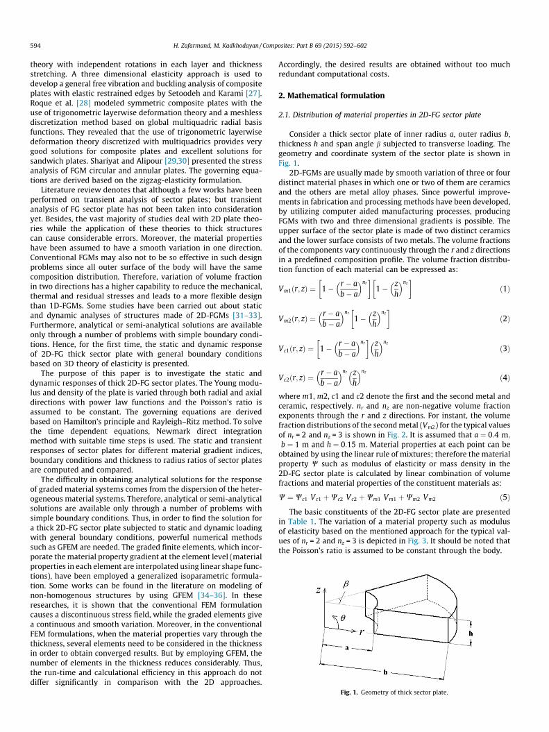
Consider a thick sector plate of inner radius a, outer radius b,thickness h and span angle b subjected to transverse loading. Thegeometry and coordinate system of the sector plate is shown inFig. 1.
2D-FGMs are usually made by smooth variation of three or fourdistinct material phases in which one or two of them are ceramicsand the others are metal alloy phases. Since powerful improve-ments in fabrication and processing methods have been developed,by utilizing computer aided manufacturing processes, producingFGMs with two and three dimensional gradients is possible. Theupper surface of the sector plate is made of two distinct ceramicsand the lower surface consists of two metals. The volume fractionsof the components vary continuously through the r and z directionsin a predefined composition profile. The volume fraction distribu-tion function of each material can be expressed as:
Vm1ðr; zÞ ¼ 1� r � ab� a
� �nr� �
1� zh
� �nz� �
ð1Þ
Vm2ðr; zÞ ¼r � ab� a
� �nr
1� zh
� �nz� �
ð2Þ
Vc1ðr; zÞ ¼ 1� r � ab� a
� �nr� �
zh
� �nz
ð3Þ
Vc2ðr; zÞ ¼r � ab� a
� �nr zh
� �nz
ð4Þ
where m1, m2, c1 and c2 denote the first and the second metal andceramic, respectively. nr and nz are non-negative volume fractionexponents through the r and z directions. For instant, the volumefraction distributions of the second metal (Vm2) for the typical valuesof nr = 2 and nz = 3 is shown in Fig. 2. It is assumed that a ¼ 0:4 m;
b ¼ 1 m and h ¼ 0:15 m. Material properties at each point can beobtained by using the linear rule of mixtures; therefore the materialproperty W such as modulus of elasticity or mass density in the2D-FG sector plate is calculated by linear combination of volumefractions and material properties of the constituent materials as:
W ¼ Wc1 Vc1 þWc2 Vc2 þWm1 Vm1 þWm2 Vm2 ð5Þ
The basic constituents of the 2D-FG sector plate are presentedin Table 1. The variation of a material property such as modulusof elasticity based on the mentioned approach for the typical val-ues of nr = 2 and nz = 3 is depicted in Fig. 3. It should be noted thatthe Poisson’s ratio is assumed to be constant through the body.
Fig. 1. Geometry of thick sector plate.

Fig. 2. Volume fraction distribution of m2 with nr = 2 and nz = 3.
Fig. 3. Distribution of elasticity modulus with nr = 2 and nz = 3.
Table 1Basic constituents of the 2D-FG sector plate.
Constituents E (GPa) q (kg/m3) t
m1 115 4515 0.3m2 70 2715 0.3c1 440 3210 0.3c2 380 3800 0.3
H. Zafarmand, M. Kadkhodayan / Composites: Part B 69 (2015) 592–602 595
2.2. Governing equations
Governing equations may be obtained based on the Hamilton’sprinciple:Z t2
t1
dI dt ¼Z t2
t1
dðU �W � TÞ dt ¼ 0 ð6Þ
where U, W and T are potential energy, work done by external forcesand kinetic energy, respectively. These functions and their varia-tions are:
U ¼ 12
ZZZX
eT � r dX ð7Þ
dU ¼ZZZ
X
deT � r dX ð8Þ
W ¼Z Z
C
PT � U dC ð9Þ
dW ¼Z Z
C
PT � dU dC ð10Þ
T ¼ 12
ZZZC
q _UT � _UdX ð11Þ
dT ¼ZZZ
X
q _UT � d _UdX ð12Þ
where X and C are the volume and area of the domain under con-sideration, q is the mass density that depends on r and z coordi-nates and P is the vector of surface traction and in the currentwork is defined as:
P ¼ f0 0 pzgT ð13Þ
Substituting Eqs. (7)–(12) in Hamilton’s principle, applying sideconditions dUjt1 ;t2
¼ 0 and using part integration:ZZZX
deT � rdXþZZZ
X
q€UT � dU dX ¼Z Z
C
PT � dU dC ð14Þ
The stress–strain relation from the Hook’s law in the matrixform is as [37]:
r ¼ D � e ð15Þ
where the stress and strain components and the coefficients of elas-ticity D, are as following [37]:
r ¼ frr rh rz rhz rrz rrh gT ð16Þ
e ¼ f er eh ez chz crz crh gT ð17Þ
D ¼ Eðr; zÞð1þ tÞð1� 2tÞ
1� t t t 0 0 0t 1� t t 0 0 0t t 1� t 0 0 00 0 0 1�2t
2 0 00 0 0 0 1�2t
2 00 0 0 0 0 1�2t
2
2666666664
3777777775ð18Þ
in which t denotes the Poisson’s ratio that is assumed to be con-stant and E is the Young’s modulus of elasticity that depends on rand z coordinates.
The strain–displacement equations based on the linear theoryof elasticity in cylindrical coordinate are [37]:
er ¼@u@r; eh ¼
1r
uþ @v@h
� �; ez ¼
@w@z
chz ¼@v@zþ 1
r@w@h
; crz ¼@u@zþ @w@r
; crh ¼1r@u@hþ @v@r� v
r
ð19Þ
where u, v and w are radial, circumferential and axial componentsof displacement, respectively. Eq. (19) can be formulated in thematrix form as:
e ¼ L � U ð20Þ
in which U is displacement vector and L is a matrix containing par-tial differentiating equations as follow:
U ¼ fu v w gT ð21Þ
L ¼@r 1=r 0 0 @z 1=r@h
0 1=r@h 0 @z 0 @r � 1=r0 0 @z 1=r@h @r 0
264
375
T
ð22Þ

596 H. Zafarmand, M. Kadkhodayan / Composites: Part B 69 (2015) 592–602
The sector plate is subjected to transverse loading and theboundary conditions used in this study are defined as follow:
CCCC :r ¼ a; b
h ¼ 0;b
�! ju ¼ v ¼ w ¼ 0
SSSS :r ¼ a; b ! v ¼ w ¼ 0jh ¼ 0;b ! u ¼ w ¼ 0j
�
CSCS :r ¼ a; b ! u ¼ v ¼ w ¼ 0jh ¼ 0; b ! u ¼ w ¼ 0j
�
FSFS : h ¼ 0;b ! u ¼ w ¼ 0jf ð23Þ
2.3. Graded finite element modeling
In order to solve the governing equations, the GFEM isemployed. In this method, in addition to displacement field, theheterogeneity of the material properties of the FGM may also bedetermined based on their nodal values. In this regard, shapefunctions similar to those of the displacement field may be used.Therefore, a GFEM is used to effectively trace smooth variationsof the material properties at the element level. Using the gradedelements for modeling of gradation of the material leads to moreaccurate results than dividing the solution domain into homoge-nous elements.
The thick sector plate is divided into a number of 8-node linearelements. The element displacements in three directions areapproximated as follows:
UðeÞ ¼ U � KðeÞ ð24Þ
where U is the matrix of linear shape functions in cylindrical coor-dinate and KðeÞ is the element nodal displacement vector that are as:
U ¼U1 0 0 � � � U8 0 00 U1 0 � � � 0 U8 00 0 U1 � � � 0 0 U8
264
375 ð25Þ
KðeÞ ¼ fU1 V1 W1 � � � U8 V8 W8 gT ð26Þ
The components of U are given in Appendix A.To treat the material inhomogeneity by using the GFEM, it may
be written that:
WðeÞ ¼X8
i¼1
WiUi ð27Þ
where WðeÞ is the material property of the element.Substituting Eq. (24) in Eq. (20) gives the element strain matrix
as:
eðeÞ ¼ B � KðeÞ ð28Þ
where
B ¼ L �UðeÞ ð29Þ
By imposing Eqs. (15), (24) and (28) into Hamilton’s principle(Eq. (14)) for each element, it can be achieved that:
dKðeÞTZZZXðeÞ
qUT �UdX
8><>:
9>=>;€KðeÞ þ dKðeÞ
TZZZXðeÞ
BT � D � BdX
8><>:
9>=>;KðeÞ
¼ dKðeÞTZ Z
CðeÞ
UT � PdC ð30Þ
Since dKðeÞT
is the variation of the nodal displacements and isarbitrary, it can be omitted from Eq. (30) and in a compact formit can be formulated as:
MðeÞ €KðeÞ þ KðeÞKðeÞ ¼ FðeÞ ð31Þ
where the characteristic matrices are defined as:
MðeÞ ¼ZZZXðeÞ
qUT �U dX ð32Þ
KðeÞ ¼ZZZXðeÞ
BT � D � B dX ð33Þ
FðeÞ ¼ZZZ
CðeÞ
UT � P dC ð34Þ
Due to dependency of D and q to the r and z coordinates, forobtaining the characteristic matrices for each element, numericalintegration using 8-point Gauss–Legendre technique should beapplied [38]. Now by assembling the element matrices and impos-ing the boundary conditions, the global equations of motion for the2D-FG sector plate can be written as:
M€Kþ KK ¼ F ð35Þ
In order to solve Eq. (35) in the space and time domains differ-ent numerical methods can be employed. In the current work,Newmark’s numerical integration method with suitable time stepsis used. Newmark integration parameters [38] are taken as c ¼ 1=2and b ¼ 1=4 which lead to a constant average acceleration. Thischoice of parameters corresponds to the trapezoidal rule which isunconditionally stable in linear analyses. Moreover, in the case ofstatic analysis, Eq. (35) is reduced to:
KK ¼ F ð36Þ
Once the finite element equations are established, the displace-ments and stresses would be found by Eqs. (35), (36) and (15),respectively. It should be noted that calculated stresses are oftenmost accurate at Gauss points. Thus, in this research, stresses atnodes are obtained by extrapolation or interpolation from Gausspoint values.
3. Numerical results and discussions
3.1. Convergence study
In order to examine the efficiency and accuracy of the presentedFE code, the results should be compared with an exact 3D solution.Since there is no study available in the literature for 3D solution ofsector plates, the results are compared with the available exact 3Dsolution for FG rectangular plate given by Kashtalyan [39]. For thispurpose, by considering very large values for a and b together witha very small value for b, the governing equations and presentedsolution procedure may also be employed for bending analysis ofrectangular plates. The relationship between length and width ofthe rectangular plate can be considered as b(a + b)/2 and b � a,respectively. First, the effects of mesh density on the obtainedresults for an FG square plate with simply supported boundaryconditions under sinusoidal load with length to thickness ratio of3, are examined and presented in Fig. 4. Numerous mesh densitiescontaining 4 � 4 � 4, 6 � 6 � 6, . . ., 22 � 22 � 22 regularly placedalong the r, h and z directions are considered. In which w⁄ refersto the exact solution of the centroid deflection obtained byKashtalyan [39]. According to this figure, it is observed that asthe mesh density increases more than 18 � 18 � 18, the normal-ized deflection (w/w⁄) does not vary considerably. Moreover, theinfluence of mesh density along the plate thickness direction isdepicted in Fig. 5. In this figure, various mesh densities containing18 � 18 � 4, 18 � 18 � 6, . . ., 18 � 18 � 14 have been considered. It

0 0.1 0.2 0.3 0.4 0.5 0.6 0.7 0.8 0.9 10
0.5
1
1.5
2
2.5
x 10-3
θ/β
w**
Ref. [7] (n=1)Ref. [7] (n=2)Ref. [7] (n=4)Present (n=1)Present (n=2)Present (n=4)
Fig. 6. Variation of the normalized deflection (w⁄⁄) along the centerline for differentvolume fraction exponent n compared with [7].
4×4×4 6×6×6 8×8×8 10×10×10 12×12×12 14×14×14 16×16×16 18×18×18 20×20×20 22×22×22
0.97
0.98
0.99
1
1.01
Mesh density
w/w*
Fig. 4. Convergence of the results for the normalized deflection with various meshdensities.
H. Zafarmand, M. Kadkhodayan / Composites: Part B 69 (2015) 592–602 597
can be observed that considering 14 meshes along the platethickness direction led to the exact solution. Therefore, to obtainthe solutions in the presented study, the mesh density is assumedto be 18 � 18 � 14 (4536 elements, 5415 nodes and 16,245degrees of freedom).
3.2. Verification
In order to verify the prepared 3D GFEM code for static anddynamic analyses of the 2D-FG sector plate, three comparisonstudies are performed as follow:
Sample 1: As a first case study, the results of moderately thickFG sector plate can be used [7]. Material distribution is assumed tobe as 1D-FG which varies in thickness direction from pure metal(Em = 70 GPa, tm = 0.3) to pure ceramic (Ec = 380 GPa, tc = 0.3) witha simple power law function. The boundary condition is fullclamped at all side edges, the sector plate is under uniform pres-sure (p) and the geometry is defined as:
a ¼ 3 m; b ¼ 5 m; h ¼ 0:3 m; b ¼ p=4 ð37Þ
The comparison of normalized deflection (w⁄⁄ = wEch3/pb4)
along the centerline (r = (a + b)/2, h) with the published data fordifferent volume fraction exponents is shown in Fig. 6 and a goodagreement between them is observed.
Sample 2: In the second example, a comparison study is accom-plished for dimensionless deflection ( �w ¼ wEmh3
=12ð1� t2Þpb4)and shear stress (�srz ¼ srz=p) of bending analysis in a simplysupported FG solid sector plate which its solution is presented bySahraee [40], where the governing equations are based on Levinsonplate theory (LPT). The thickness to radius ratio is taken as 0.1 and
18×18×4 18×18×6 18×18×8 18×18×10 18×18×12 18×18×14
1
1.005
1.01
1.015
Mesh density
w/w*
Fig. 5. Convergence of the results for the normalized deflection with various meshdensities along the plate thickness.
the ratio of Young’s modulus of metal component to ceramic com-ponent is assumed to be 0.4636. The results for different volumefraction exponents are demonstrate in Table 2, where the presentresults are in a good agreement with the other solution.
Sample 3: As a final part of verification, the dynamic behavior ofan isotropic sector plate subjected to impact loading with clampedboundary condition is calculated and compared with the results ofcommercial FEA software [41]. The geometry, material and loadingfunction are assumed to be as:
a ¼ 0:4 m; b ¼ 1 m; h ¼ 0:1 m; b ¼ p=4E ¼ 70 GPa t ¼ 0:3
ð38Þ
pzðtÞ ¼P0t t 6 t0
0 t > t0
�ð39Þ
where P0 and t0 are assumed to be as 2� 104 MPa and 5� 10�4 s,respectively. The comparison of time histories of centroid deflectionand axial stress with the Abaqus’ results are depicted in Figs. 7 and8. It is obvious that the present solutions are in good consistencywith the software results.
3.3. Static analysis
Consider a 2D-FG thick sector plate with inner radius ofa = 0.4 m, outer radius of b = 1 m, span angle of b = p/3 and sub-jected to uniform pressure of P0 ¼ 10 MPa. Constituent materialsare two distinct ceramics and two distinct metals described inTable 1.
First, the effect of power law exponents (nr, nz) on the staticresponse of the sector plate is studied. The thickness to radius ratioof the sector plate and the boundary conditions are assumed to beh/b = 0.1 and CCCC, respectively. Fig. 9 shows the variation ofcentral deflection along the radial direction at z = 0 and h = b/2for different power law exponents. According to this figure,deflection increase as nz increases and nr decreases, this behavior
Table 2Dimensionless deflection and shear stress for different volume fraction exponentcompared with [40].
n �w ð0:75b; p=4; 0Þ �srz ð0:75 b; p=6; 0Þ
Present Ref. [40] Present Ref. [40]
0 1.1721 1.1613 �0.6691 �0.66092 1.3112 1.2946 �0.6864 �0.67895 2.1893 2.1758 �0.7007 �0.6916

0 1 2 3 4 5 6 7 8x 10
-4
-4
-3
-2
-1
0
1
2
3
4 x 10⁻⁴
Time (s)
Def
lect
ion
(m)
PresentAbaqus
Fig. 7. Time history of centroid deflection compared with Abaqus.
5.1 5.2 5.3 5.4 5.5 5.6 5.7 5.8 5.9 6x 10
-4
-8
-6
-4
-2
0
2
4
6
8
Time (s)
Axia
l stre
ss (M
Pa)
PresentAbaqus
Fig. 8. Time history of centroid axial stress compared with Abaqus.
598 H. Zafarmand, M. Kadkhodayan / Composites: Part B 69 (2015) 592–602
is due to the resulting decrease in the modulus of elasticity. More-over, the influence of changing nz on the deflection is more notice-able than changing nr. The variations of radial stress through theradial direction at z = 0 and h = b/2, and circumferential stressalong the centerline at z = 0 and r = (a + b)/2 for different powerlaw exponents are illustrated in Figs. 10 and 11, respectively. It isseen that by increasing nr and nz, the radial and circumferentialstresses rises, in which changing nz has a more effect on variation
0.4 0.5 0.6 0.7 0.8 0.9 10
1
2
x 10-4
Radial direction (m)
Def
lect
ion
(m)
nr=nz=0.5nr=0.5, nz=1nr=0.5, nz=2nr=2, nz=0.5nr=5, nz=0.5
Fig. 9. Variation of central deflection through the radial direction at z = 0 and h = b/2 for different power law exponents.
of stresses rather than nr. Furthermore, Fig. 12 demonstrates thevariation of radial stress through the thickness direction atr = (a + b)/2 and h = b/2 for different power law exponents. This fig-ure shows that there is a compression at the top surface and ten-sion at the bottom surface, in which the magnitude of radialstress at the top surface (ceramic) is significantly larger than thatof the bottom surface (metal). Moreover, the neutral plane (whererr vanishes) goes upper with increasing of power law exponent.
Now, the effect of thickness to radius ratio (h/b) on the staticresponse of the sector plate is investigated. The power law expo-nents and boundary conditions are assumed to be nr = 2, nz = 3and CCCC, respectively. Fig. 13 displays the variation of centraldeflection through the radial direction at z = 0 and h = b/2 for dif-ferent thickness to radius ratios. According to this figure, thicknessto radius ratio has a high influence on the deflection of the sectorplate. The variations of radial stress through the radial directionat z = 0 and h = b/2, and circumferential stress along the centerlineat z = 0 and r = (a + b)/2 for different thickness to radius ratios areillustrated in Figs. 14 and 15, respectively. From these figures, itcan be observed that by tripling the thickness to radius ratio ofthe plate, the stresses may be reduced up to 90%. Moreover,Fig. 16 shows the variation of radial stress versus non-dimensionalthickness (z/h) at r = (a + b)/2 and h = b/2 for different thickness toradius ratios. From this figure, the non-dimensional position ofneutral plane remains unchanged when thickness to radius ratiovaries. Furthermore, the effect of boundary condition on the staticbehavior of the sector plate for different thickness to radius ratiosand power law exponents is tabulated in Table 3. The results showthat the influence of boundary condition on deflection is more sig-nificant than that of stresses.
3.4. Dynamic analysis
Consider the 2D-FG sector plate of the previous section onceagain. As already mentioned, it is assumed that the sector plateis fabricated from two distinct ceramics and metals as describedin Table 1. The sector plate is subjected to an impact loading atthe top surface. The loading function is assumed as:
pzðtÞ ¼P0 sin pt
t0
� �t 6 t0
0 t > t0
(ð40Þ
where P0 and t0 are loading constants that are assumed to be as10 MPa and 5 � 10�4 s, respectively. Variation of the lateral impactpressure with time is displayed in Fig. 17. According to this figure,the sector plate is excited by unloading in t0 ¼ 5� 10�4 s. It is obvi-ous that after unloading, a transient vibration which is affected by
0.4 0.5 0.6 0.7 0.8 0.9 1
-100
-80
-60
-40
-20
0
20
40
60
r/b
Radi
al st
ress
(MPa
)
nr=nz=0.5nr=0.5, nz=5nr=5, nz=0.5nr=nz=5
Fig. 10. Variation of radial stress through the radial direction at z = 0 and h = b/2 fordifferent power law exponents.

0.4 0.5 0.6 0.7 0.8 0.9 10
0.2
0.4
0.6
0.8
1
1.2
x 10-3
r/b
Def
lect
ion
(m)
h/b=0.05h/b=0.075h/b=0.1h/b=0.15
Fig. 13. Variation of central deflection through the radial direction at z = 0 andh = b/2 for different thickness to radius ratios.
0 0.1 0.2 0.3 0.4 0.5 0.6 0.7 0.8 0.9 1-300
-250
-200
-150
-100
-50
0
50
100
150
θ/β
Circ
umfe
rent
ial s
tress
(MPa
)
h/b=0.05h/b=0.075h/b=0.1h/b=0.15
Fig. 15. Variation of circumferential stress along the center line at z = 0 andr = (a + b)/2 for different thickness to radius ratios.
0.4 0.5 0.6 0.7 0.8 0.9 1-400
-300
-200
-100
0
100
200
r/b
Radi
al st
ress
(MPa
)
h/b=0.05h/b=0.075h/b=0.1h/b=0.15
Fig. 14. Variation of radial stress through the radial direction at z = 0 and h = b/2 fordifferent thickness to radius ratios.
0 0.1 0.2 0.3 0.4 0.5 0.6 0.7 0.8 0.9 1-400
-300
-200
-100
0
100
200
z/h
Radi
al st
ress
(MPa
)
h/b=0.05h/b=0.075h/b=0.1h/b=0.15
Fig. 16. Variation of radial stress through the thickness direction at r = (a + b)/2 andh = b/2 for different thickness to radius ratios.
0 0.1 0.2 0.3 0.4 0.5 0.6 0.7 0.8 0.9 1
θ/β
Circ
umfe
rent
ial s
tress
(MPa
)
nr=nz=0.5nr=0.5, nz=5nr=5, nz=0.5nr=nz=5
-80
-60
-40
-20
0
20
40
Fig. 11. Variation of circumferential stress along the centerline at z = 0 andr = (a + b)/2 for different power law exponents.
0 0.1 0.2 0.3 0.4 0.5 0.6 0.7 0.8 0.9 1-120
-100
-80
-60
-40
-20
0
20
40
60
z/h
Radi
al st
ress
(MPa
)
nr=nz=0nr=nz=0.5nr=nz=1nr=nz=2
Fig. 12. Variation of radial stress through the thickness direction at r = (a + b)/2 andh = b/2 for different power law exponents.
H. Zafarmand, M. Kadkhodayan / Composites: Part B 69 (2015) 592–602 599
the wave propagation, reflection and interference would beoccurred. The three dimensional transient analysis for different val-ues of the power law exponents and thickness to radius ratio arepresented and discussed as following.
Fig. 18 shows the time history of the central deflection of thesector plate for different power law exponents with thicknessto radius ratio of h/b = 0.1 and CCCC boundary condition. Accordingto this figure, by increasing the power law exponents, the
amplitude of vibrations increases. The time history of the stresscomponents rz and rr at the center point of the sector plate(r = (a + b)/2, h = b/2, z = h/2) after unloading for different powerlaw exponents with thickness to radius ratio of h/b = 0.1 and CCCCboundary condition are illustrated in Figs. 19 and 20. These resultsreveal how the propagation of the stress wave following theunloading is highly affected by the variation of volume fractionof the constituent materials in two directions. In which, by
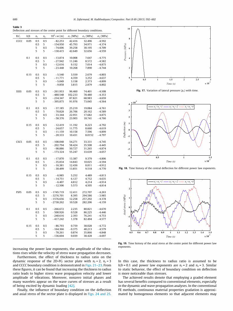
Table 3Deflection and stresses of the center point for different boundary conditions.
B.C. h/b nr nz 105�w (m) rr (MPa) rh (MPa) rz (MPa)
CCCC 0.05 0.5 0.5 �82.253 42.416 32.496 �4.5920.5 5 �154.950 45.793 34.971 �4.3745 0.5 �74.606 39.258 30.195 �4.7095 5 �130.415 42.649 32.656 �4.559
0.1 0.5 0.5 �13.874 10.008 7.647 �4.7750.5 5 �27.942 11.246 8.572 �4.5825 0.5 �12.616 9.152 7.014 �4.8755 5 �23.448 10.268 7.890 �4.744
0.15 0.5 0.5 �5.540 3.559 2.679 �4.8030.5 5 �11.771 4.359 3.252 �4.6375 0.5 �5.049 3.158 2.373 �4.8995 5 �9.858 3.815 2.879 �4.802
SSSS 0.05 0.5 0.5 �261.953 96.460 74.401 �4.5080.5 5 �480.548 102.233 78.480 �4.3535 0.5 �234.347 87.821 68.983 �4.6595 5 �395.875 91.976 73.045 �4.564
0.1 0.5 0.5 �37.185 25.219 19.084 �4.7610.5 5 �70.828 26.706 20.162 �4.5895 0.5 �33.344 22.951 17.682 �4.8755 5 �58.376 23.903 18.741 �4.766
0.15 0.5 0.5 �12.419 11.192 8.223 �4.7920.5 5 �24.657 11.775 8.660 �4.6195 0.5 �11.159 10.158 7.596 �4.8995 5 �20.333 10.431 8.0152 �4.797
CSCS 0.05 0.5 0.5 �108.048 54.271 33.331 �4.7450.5 5 �202.794 58.424 35.508 �4.4455 0.5 �98.886 50.727 31.265 �4.8745 5 �173.324 55.247 33.639 �4.657
0.1 0.5 0.5 �17.870 13.387 9.379 �4.8060.5 5 �35.834 14.843 10.025 �4.5945 0.5 �16.381 12.436 8.811 �4.9125 5 �30.499 13.851 9.518 �4.770
0.15 0.5 0.5 �6.985 5.252 4.489 �4.8130.5 5 �14.751 6.127 4.752 �4.6355 0.5 �6.407 4.812 4.214 �4.9145 5 �12.506 5.573 4.505 �4.814
FSFS 0.05 0.5 0.5 �1745.719 12.411 272.707 �4.2630.5 5 �3276.701 8.395 294.586 �3.9855 0.5 �1576.656 12.258 257.292 �4.3785 5 �2738.262 10.528 282.206 �4.159
0.1 0.5 0.5 �266.672 2.235 80.821 �4.6700.5 5 �500.926 0.528 86.225 �4.4465 0.5 �240.616 2.393 76.241 �4.7535 5 �417.242 1.378 82.494 �4.577
0.15 0.5 0.5 �86.793 0.759 38.028 �4.7720.5 5 �164.366 �0.375 40.213 �4.5795 0.5 �78.261 0.874 35.866 �4.8485 5 �136.604 0.039 38.428 �4.697
0 0.5 1 1.5 2 2.5 3x 10
-3
0
2
4
6
8
10
Time (s)
Pres
sure
(MPa
)
Fig. 17. Variation of lateral pressure (pz) with time.
0 0.5 1 1.5x 10
-3
-4
-3
-2
-1
0
1
2
3
4 x 10⁻⁴
Time (s)
Def
lect
ion
(m)
nr=nz=1 nr=nz=2 nr=nz=4
Fig. 18. Time history of the central deflection for different power law exponents.
0.5 0.6 0.7 0.8 0.9 1 1.1 1.2 1.3 1.4 1.5x 10
-3
-2
-1
0
1
2
3
Time (s)
Axia
l stre
ss (M
Pa)
nr=nz=1 nr=nz=2 nr=nz=4
Fig. 19. Time history of the axial stress at the center point for different power lawexponents.
600 H. Zafarmand, M. Kadkhodayan / Composites: Part B 69 (2015) 592–602
increasing the power law exponents, the amplitude of the vibra-tions rises while the velocity of stress wave propagation decreases.
Furthermore, the effect of thickness to radius ratio on thedynamic response of the 2D-FG sector plate with nr = 2, nz = 3and CCCC boundary condition is demonstrated in Figs. 21–23. Fromthese figures, it can be found that increasing the thickness to radiusratio leads to higher stress wave propagation velocity and loweramplitude of vibrations. Moreover, nonzero initial phases andmany wavelets appear on the wave curves of stresses as a resultof being excited by dynamic loading [42].
Finally, the influence of boundary condition on the deflectionand axial stress of the sector plate is displayed in Figs. 24 and 25.
In this case, the thickness to radius ratio is assumed to beh/b = 0.1 and power law exponents are nr = 2 and nz = 3. Similarto static behavior, the effect of boundary condition on deflectionis more noticeable than stresses.
The achieved results denote that employing a graded elementhas several benefits compared to conventional elements, especiallyin the dynamic and wave propagation analyses. In the conventionalFE methods, continuous material properties gradation is approxi-mated by homogenous elements so that adjacent elements may

0 0.5 1 1.5x 10
-3
-3
-2
-1
0
1
2
3 x 10⁻³
Time (s)
Def
lect
ion
(m)
h/b=0.05 h/b=0.075 h/b=0.1
Fig. 21. Time history of the central deflection for different thickness to radiusratios.
0.5 0.6 0.7 0.8 0.9 1 1.1 1.2 1.3 1.4 1.5x 10
-3
-0.05
0
0.05
Time (s)
Shea
r stre
ss (M
Pa)
h/b=0.05 h/b=0.075 h/b=0.1 h/b=0.15
Fig. 23. Time history of the shear stress (rrh) at the center point for differentthickness to radius ratios.
0 0.5 1 1.5x 10
-3
-3
-2
-1
0
1
2 x 10⁻³
Time (s)
Def
lect
ion
(m)
CCCC SSSS CSCS FSFS
Fig. 24. Time history of the central deflection for different boundary conditions.
0.5 0.6 0.7 0.8 0.9 1 1.1 1.2 1.3 1.4 1.5x 10
-3
-20
-15
-10
-5
0
5
10
15
20
Time (s)
Radi
al st
ress
(MPa
)
nr=nz=1 nr=nz=2 nr=nz=4
Fig. 20. Time history of the radial stress at the center point for different power lawexponents.
0.5 0.6 0.7 0.8 0.9 1 1.1 1.2 1.3 1.4 1.5x 10
-3
-4
-3
-2
-1
0
1
2
3
4
5
Time (s)
Axia
l stre
ss (M
Pa)
h/b=0.05 h/b=0.075 h/b=0.1 h/b=0.15
Fig. 22. Time history of the axial stress at the center point for different thickness toradius ratios.
0.5 0.6 0.7 0.8 0.9 1 1.1 1.2 1.3 1.4 1.5x 10
-3
-4
-3
-2
-1
0
1
2
3
4
Time (s)
Axia
l stre
ss (M
Pa)
CCCC SSSS CSCS FSFS
Fig. 25. Time history of the axial stress at the center point for different boundaryconditions.
H. Zafarmand, M. Kadkhodayan / Composites: Part B 69 (2015) 592–602 601
have quite different isotropic material properties. Thus, jumps inthe material properties are observed at the boundaries of thesehomogenous elements and this phenomenon causes artificial wavereflections which has in turn cumulative effects on magnitude andstress wave propagation velocity. Therefore, by using the gradedelements wherein the material properties vary continuously inthe element scale, the desired accuracy may be obtained withoutrefining the mesh size.
4. Conclusion
The main purpose of the present research was to investigate the3D static and dynamic behavior of 2D-FG thick sector plates. Thegoverning equations were based on the 3D theory of elasticity. Inorder to solve the equations in space and time domains, the 3DGFEM based on Hamilton’s principle and Rayleigh–Ritz energy for-mulation was applied. The proposed method was verified by threeexamples. The comparisons between the results showed that the

602 H. Zafarmand, M. Kadkhodayan / Composites: Part B 69 (2015) 592–602
present method had a good agreement with the existing results.Different types of displacement and stresses in three directionswere presented for various values of power law exponents andthickness to radius ratios of the thick sector plate. Newmark’snumerical integration method was employed to derive time histo-ries of the displacement and stress components. Results denotethat the static and dynamic responses of the structure can be con-trolled and optimized by variation of the material properties in twodirections. In other words, by selecting proper heterogeneityparameters, the distribution of the deflection and stress compo-nents can be modified to satisfy the desirable requirements. Fur-thermore, results confirm that using 2D-FGMs leads to moreflexible designs compared to 1D-FGMs.
Appendix A
The components of U are:
Ui ¼1X
C � X ðA1Þ
where X is the volume of each element that is:
X ¼
1 n1 g1 f1 n1g1 n1f1 g1f1 n1g1f1
1 n2 g2 f2 n2g2 n2f2 g2f2 n2g2f2
1 n3 g3 f3 n3g3 n3f3 g3f3 n3g3f3
1 n4 g4 f4 n4g4 n4f4 g4f4 n4g4f4
1 n5 g5 f5 n5g5 n5f5 g5f5 n5g5f5
1 n6 g6 f6 n6g6 n6f6 g6f6 n6g6f6
1 n7 g7 f7 n7g7 n7f7 g7f7 n7g7f7
1 n8 g8 f8 n8g8 n8f8 g8f8 n8g8f8
ðA2Þ
and
Cij ¼ ð�1Þiþjj� ijj ðA3Þ
X ¼ f1; n;g; f; ng; nf;gf; ngfgT ðA4Þ
in which
n ¼ r cos h; g ¼ r sin h; f ¼ z ðA5Þ
ni ¼ ri cos hi; gi ¼ ri sin hi; fi ¼ zi ðA6Þ
where ri, hi and zi are nodal coordinates and � ij is obtained fromeliminating the ith row and jth column of X.
References
[1] Miyamoto Y, Kaysser WA, Rabin BH. Functionally graded materials: design,processing and applications. Kluwer, Dordrecht; 1999.
[2] Koizumi M. The concept of FGM. Ceram Trans, Functionally Gradient Mater1993;34:3–10.
[3] Kobayashi H, Turvey GJ. Elastic small deflection analysis of annular sectorMindlin plates. Int J Mech Sci 1994;36(9):811–27.
[4] Salehi M, Turvey GJ. Elastic large deflection response of annular sector plates, acomparison of DR finite-difference, finite element and other numericalsolutions. Comput Struct 1991;40(5):1267–91.
[5] Salehi M, Shahidi A. Large deflection analysis of elastic Mindlin sector plates.Comput Struct 1994;52(5):987–98.
[6] Aghdam MM, Mohammadi M, Erfanian V. Bending analysis of thin annularsector plates using extended Kantorovich method. Thin-Walled Struct2007;45:983–90.
[7] Aghdam MM, Shahmansouri N, Mohammadi M. Extended Kantorovich methodfor static analysis of moderately thick functionally graded sector plates. MathComput Simul 2012;86:118–30.
[8] Aghdam MM, Mohammadi M. Bending analysis of thick orthotropic sectorplates with various loading and boundary conditions. Compos Struct2009;88:212–8.
[9] Mousavi SM, Tahani M. Analytical solution for bending of moderately thickradially functionally graded sector plates with general boundary conditionsusing multi-term extended Kantorovich method. Composites B2012;43:1405–16.
[10] Tahani M, Mousavi SM. Analytical solution for bending problem of moderatelythick composite annular sector plates with general boundary conditions andloadings using multi-term extended Kantorovich method. Arch Appl Mech2013;83:969–85.
[11] Jomehzadeh E, Saidi AR, Atashipour SR. An analytical approach for stress analysisof functionally graded annular sector plates. Mater Des 2009;30:3679–85.
[12] Malekzadeh P, Golbahar Haghighi MR, Gholami M. Dynamic response of thicklaminated annular sector plates subjected to moving load. Compos Struct2010;92:155–63.
[13] Sharma A, Nath Y, Sharda HB. Nonlinear transient analysis of moderately thicklaminated composite sector plates. Commun Nonlinear Sci Numer Simul2007;12:1101–14.
[14] Alibeigloo A. Three-dimensional thermo-elasticity solution of sandwichcylindrical panel with functionally graded core. Compos Struct2014;107:458–68.
[15] Shariyat M, Asemi K. Three-dimensional non-linear elasticity-based 3D cubicB-spline finite element shear buckling analysis of rectangular orthotropic FGMplates surrounded by elastic foundations. Compos B 2014;56:934–47.
[16] Jabbari M, Shahryari E, Haghighat H, Eslami MR. An analytical solution forsteady state three dimensional thermoelasticity of functionally graded circularplates due to axisymmetric loads. Eur J Mech A/Solids 2014;47:124–42.
[17] Asemi K, Salehi M, Akhlaghi M. Three dimensional biaxial buckling analysis offunctionally graded annular sector plate fully or partially supported onWinkler elastic foundation. Aerosp Sci Technol. doi: 10.1016/j.ast.2014.04.011.
[18] Asemi K, Salehi M, Akhlaghi M. Post-buckling analysis of FGM annular sectorplates based on three dimensional elasticity graded finite elements. Int J Non-Linear Mech 2014;67:164–77.
[19] Hosseini-Hashemi Sh, Salehipour H, Atashipour SR, Sburlati R. On the exact in-plane and out-of-plane free vibration analysis of thick functionally gradedrectangular plates: explicit 3-D elasticity solutions. Composites B2013;46:108–15.
[20] Attallah KMZ, Yu M, Ye JQ. Three-dimensional state space spline finite stripanalysis of angle-plied laminates. Composites B 2014;66:25–35.
[21] Cheng ZQ, Batra RC. Three-dimensional thermoelastic deformations of afunctionally graded elliptic plate. Composites B 2000;31:97–106.
[22] Na KS, Kim JH. Three-dimensional thermal buckling analysis of functionallygraded materials. Composites B 2004;35:429–37.
[23] Malekzadeh P, Afsari A, Zahedinejad P, Bahadori R. Three-dimensionallayerwise-finite element free vibration analysis of thick laminated annularplates on elastic foundation. Appl Math Model 2010;34:776–90.
[24] Setoodeh AR, Tahani M, Selahi E. Transient dynamic and free vibration analysisof functionally graded truncated conical shells with non-uniform thicknesssubjected to mechanical shock loading. Composites B 2012;43:2161–71.
[25] Andakhshideh A, Tahani M. Interlaminar stresses in general thick rectangularlaminated plates under in-plane loads. Composites B 2013;47:58–69.
[26] Maturi DA, Ferreira AJM, Zenkour AM, Mashat DS. Analysis of sandwich plateswith a new layerwise formulation. Composites B 2014;56:484–9.
[27] Setoodeh AR, Karami G. A solution for the vibration and buckling of compositelaminates with elastically restrained edges. Compos Struct 2003;60:245–53.
[28] Roque CMC, Ferreira AJM, Jorge RMN. Modelling of composite and sandwichplates by a trigonometric layerwise deformation theory and radial basisfunctions. Composites B 2005;36:559–72.
[29] Shariyat M, Alipour MM. Semi-analytical consistent zigzag-elasticityformulations with implicit layerwise shear correction factors for dynamicstress analysis of sandwich circular plates with FGM layers. Composites B2013;49:43–64.
[30] Alipour MM, Shariyat M. Analytical stress analysis of annular FGM sandwichplates with non-uniform shear and normal tractions, employing a zigzag-elasticity plate theory. Aerosp Sci Technol 2014;32:235–59.
[31] Nemat-Alla M. Reduction of thermal stresses by composition optimization oftwo-dimensional functionally graded materials. Acta Mech 2009;208:147–61.
[32] Asemi K, Salehi M, Akhlaghi M. Elastic solution of a two-dimensionalfunctionally graded thick truncated cone with finite length underhydrostatic combined loads. Acta Mech 2011;217(1–2):119–34.
[33] Zafarmand H, Hassani B. Analysis of two-dimensional functionally gradedrotating disks with variable thickness. Acta Mech 2014;225:453–64.
[34] Kim JH, Paulino GH. Isoparametric graded finite elements for nonhomogeneousisotropic and orthotropic materials. J Appl Mech 2002;69:502–14.
[35] Ashrafi H, Asemi K, Shariyat M, Salehi M. Two-dimensional modeling ofheterogeneous structures using graded finite element and boundary elementmethods. Meccanica 2012;48:663–80.
[36] Zafarmand H, Kadkhodayan M. Three-dimensional static analysis of thickfunctionally graded plates using graded finite element method. Proc Inst MechEng, C 2014;228:1275–85.
[37] Boresi AP, Chong KP, Lee JD. Elasticity in engineering mechanics. 3rded. Hoboken, New Jersey: John Wiley & Sons Inc; 2011.
[38] Zienkiewicz OC, Taylor RL. The finite element method for solid and structuralmechanics. 6th ed. Oxford: Elsevier Butterworth-Heinemann; 2005.
[39] Kashtalyan M. Three-dimensional elasticity solution for bending offunctionally graded rectangular plates. Eur J Mech A/Solids 2004;23:853–64.
[40] Sahraee S. Bending analysis of functionally graded sectorial plates usingLevinson plate theory. Compos Struct 2009;88:548–57.
[41] Abaqus. Version 6.12-1, Dassualt Systems Inc.; 2012.[42] Xue H, Hu HP. Nonlinear characteristics of a circular plate piezoelectric
harvester with relatively large deflection near resonance. IEEE Trans UltrasonFerroelectr Freq Control 2008;55(9):2092–6.