CompositeRight-andLeft-HandedTraveling-Wave Field ...
8
Hindawi Publishing Corporation Active and Passive Electronic Components Volume 2012, Article ID 498146, 7 pages doi:10.1155/2012/498146 Research Article Composite Right- and Left-Handed Traveling-Wave Field-Effect Transistors Koichi Narahara Graduate School of Science and Engineering, Yamagata University, 4-3-16 Jonan, Yonezawa, Yamagata 992-8510, Japan Correspondence should be addressed to Koichi Narahara, [email protected] Received 27 March 2012; Revised 27 June 2012; Accepted 11 July 2012 Academic Editor: Egidio Ragonese Copyright © 2012 Koichi Narahara. This is an open access article distributed under the Creative Commons Attribution License, which permits unrestricted use, distribution, and reproduction in any medium, provided the original work is properly cited. We introduce a composite right- and left-handed travelling-wave field-effect transistor (CRLH TWFET) for developing large- scale platform to support left-handed waves. The device represents two electromagnetically coupled CRLH transmission lines by capacitance and FET transconductance. Owing to the couplings, two different modes can support waves in CRLH TWFETs. It was experimentally established that waves supported by one of the modes were amplified, while those supported by the other mode were significantly attenuated. To quantify the wave propagation in CRLH TWFETs, we developed a numerical model based on the transmission line theory that well simulated measured results. This paper discusses the results of numerical calculations that validate the design criteria of CRLH TWFETs. 1. Introduction Composite right- and left-handed (CRLH) transmission lines (TLs) have been extensively studied and several impor- tant breakthroughs have been achieved in the management of electromagnetic continuous waves [1]. CRLH TLs have a single series and shunt inductance-capacitance (LC) pair in each unit cell. They exhibit lefthandedness; that is, at certain frequencies, their phase velocity has a sign opposite to that of their group velocity. Figure 1 shows the unit cell of a CRLH TL, where L R , C L , L L , and C R are the series inductance, series capacitance, shunt inductance, and shunt capacitance, respectively. The series LC pair consists of L R and C L , and the shunt pair consists of L L and C R . These parameters define the upper and lower zero-wavelength frequencies of the CRLH TL, which are given by ω u = max(1/ (C L L R ) 1/2 ,1/ (C R L L ) 1/2 ) and ω l = min(1/ (C L L R ) 1/2 ,1/ (C R L L ) 1/2 ), respectively. The line exhibits righthandedness at frequencies greater than ω u and left-handedness at frequencies lower than ω l .A frequency band gap exists between ω l and ω u in which all supporting modes are evanescent. The use of CRLH TLs may sometimes be impractical because of their finite electrode resistance and substrate current leakage, and may require loss compensation schemes. Recently, several authors have investigated methods for amplifying LH waves in 1D using transistors [2–4]. In particular, we analyse the use of two CRLH TLs that interact continuously via transistor transconductance together with both capacitive and inductive couplings, which we call a CRLH travelling-wave field-effect transistor (TWFET), or CRLH TWFET for brevity. There are two different schemes to achieve loss com- pensation or amplification of left-handed waves. One of the methods is to interconnect passive CRLH sections with amplifier section. Based on this methodology, Casares- Miranda et al. [2] fabricated a leaky-wave antenna, whose gain was much enhanced compared to its passive coun- terpart. Multiple cascades of the interconnecting sections enable extension of the effective propagation length of a LH wave. However, a phase jump occurs at the amplifier section. Another method is continuous amplification. Si et al. [3] proposed a microwave CRLH TL incorporating ideal gain devices in each unit cell. They demonstrated a simple circuit cell consisting of two FETs operated as such gain devices. On the other hand, Maezawa et al. [4] proposed a CRLH TL periodically loaded with resonant tunnel diode (RTD) pairs. The negative differential resistance (NDR) of RTDs can compensate the loss in passive CRLH TLs. It is suggested that the line can amplify signals traveling along the line by the NDR of the RTD. In either case, the unit-cell structure is much simpler than CRLH TWFETs.
Transcript of CompositeRight-andLeft-HandedTraveling-Wave Field ...

Hindawi Publishing CorporationActive and Passive Electronic ComponentsVolume 2012, Article ID 498146, 7 pagesdoi:10.1155/2012/498146
Research Article
Composite Right- and Left-Handed Traveling-WaveField-Effect Transistors
Koichi Narahara
Graduate School of Science and Engineering, Yamagata University, 4-3-16 Jonan, Yonezawa, Yamagata 992-8510, Japan
Correspondence should be addressed to Koichi Narahara, [email protected]
Received 27 March 2012; Revised 27 June 2012; Accepted 11 July 2012
Academic Editor: Egidio Ragonese
Copyright © 2012 Koichi Narahara. This is an open access article distributed under the Creative Commons Attribution License,which permits unrestricted use, distribution, and reproduction in any medium, provided the original work is properly cited.
We introduce a composite right- and left-handed travelling-wave field-effect transistor (CRLH TWFET) for developing large-scale platform to support left-handed waves. The device represents two electromagnetically coupled CRLH transmission lines bycapacitance and FET transconductance. Owing to the couplings, two different modes can support waves in CRLH TWFETs. It wasexperimentally established that waves supported by one of the modes were amplified, while those supported by the other modewere significantly attenuated. To quantify the wave propagation in CRLH TWFETs, we developed a numerical model based onthe transmission line theory that well simulated measured results. This paper discusses the results of numerical calculations thatvalidate the design criteria of CRLH TWFETs.
1. Introduction
Composite right- and left-handed (CRLH) transmissionlines (TLs) have been extensively studied and several impor-tant breakthroughs have been achieved in the managementof electromagnetic continuous waves [1]. CRLH TLs have asingle series and shunt inductance-capacitance (LC) pair ineach unit cell. They exhibit lefthandedness; that is, at certainfrequencies, their phase velocity has a sign opposite to thatof their group velocity. Figure 1 shows the unit cell of aCRLH TL, where LR, CL, LL, and CR are the series inductance,series capacitance, shunt inductance, and shunt capacitance,respectively. The series LC pair consists of LR and CL, and theshunt pair consists of LL and CR. These parameters define theupper and lower zero-wavelength frequencies of the CRLHTL, which are given by ωu = max(1/(CLLR)1/2, 1/(CRLL)1/2)and ωl = min(1/(CLLR)1/2, 1/(CRLL)1/2), respectively. Theline exhibits righthandedness at frequencies greater thanωu and left-handedness at frequencies lower than ωl. Afrequency band gap exists between ωl and ωu in which allsupporting modes are evanescent.
The use of CRLH TLs may sometimes be impracticalbecause of their finite electrode resistance and substratecurrent leakage, and may require loss compensation schemes.Recently, several authors have investigated methods foramplifying LH waves in 1D using transistors [2–4].
In particular, we analyse the use of two CRLH TLsthat interact continuously via transistor transconductancetogether with both capacitive and inductive couplings,which we call a CRLH travelling-wave field-effect transistor(TWFET), or CRLH TWFET for brevity.
There are two different schemes to achieve loss com-pensation or amplification of left-handed waves. One ofthe methods is to interconnect passive CRLH sections withamplifier section. Based on this methodology, Casares-Miranda et al. [2] fabricated a leaky-wave antenna, whosegain was much enhanced compared to its passive coun-terpart. Multiple cascades of the interconnecting sectionsenable extension of the effective propagation length of aLH wave. However, a phase jump occurs at the amplifiersection. Another method is continuous amplification. Si et al.[3] proposed a microwave CRLH TL incorporating idealgain devices in each unit cell. They demonstrated a simplecircuit cell consisting of two FETs operated as such gaindevices. On the other hand, Maezawa et al. [4] proposed aCRLH TL periodically loaded with resonant tunnel diode(RTD) pairs. The negative differential resistance (NDR)of RTDs can compensate the loss in passive CRLH TLs.It is suggested that the line can amplify signals travelingalong the line by the NDR of the RTD. In either case, theunit-cell structure is much simpler than CRLH TWFETs.

2 Active and Passive Electronic Components
LR CL
LL CR
Figure 1: Unit cell of CRLH TL.
The CRLH TL has inductance-capacitance pairs in each unitcell. With the simple introduction of an NDR device, thesepairs can exhibit resonant behaviour. We carried out thestability analysis with respect to CRLH TWFETs to establishthe fact that they succeed in suppressing instability andamplifying the LH waves [5]. On the other hand, as far as weknow, such stability analysis has not been carried out for theschemes that employ NDR device in each unit cell. Table 1summarizes the merits and demerits of the above-mentionedthree platforms for compensating attenuation of LH waves.
In the following, we first clarify our design conceptof CRLH TWFETs. We then discuss several fundamentalproperties of a CRLH TWFET including the device configu-ration, dispersion relationship, and design criteria for waveamplification and termination schemes. Next, we describethe numerical model to simulate the measured results. Then,we numerically confirm the validity of the design criteria ofa CRLH TWFET.
2. Design Concept of CRLH TWFETs
Figure 2 illustrates our design concept of CRLH TWFETs.Owing to couplings, two different propagation modes, calledthe c- and π-modes, can support waves in CRLH TWFETs.Each mode has its own speed, characteristic impedance, andthe voltage fraction between the gate and drain lines. Ingeneral, the c-mode waves have the even parity between thegate and drain lines. On the other hand, the π-mode waveshave the odd parity between the gate and drain lines.
Our design concept stems from the fact that a CRLHTWFET can amplify the waves carried by one of two modes,and attenuate ones carried by the other mode significantly.We can exclude the influences caused by waves carriedby the attenuating mode to suppress modal dispersions.Moreover, wave reflection at the ends can be minimized bythe matched terminations with the characteristic impedancescorresponding to the amplifying mode.
At present, we consider the case where the π-mode is theunique one to be amplified. Then, the terminal resistancesRTg and RTd are set equal to the π-mode characteristicimpedances for the gate and drain lines, respectively. In orderto develop the waves carried by the π-mode, the input ports
RTd RTd
RTg RTg
Vin,d
Vin,g
Drain line
Gate line
Source
Vout,d
Vout,g
Gained
Attenuated
Black: gate, red: drain
π-mode
c-mode
Figure 2: Design concept of CRLH TWFETs.
Vin,g and Vin,d are excited by the waves satisfying the π-mode voltage fraction. In this study, we describe the resultsof numerical calculations using a model of a CRLH TWFETbased on the elemental transmission line theory. The modelwell simulates the measured properties of the device and canevaluate the contributions of the finite series inductors toboth LH and RH waves travelling in a line. The operationbandwidth is limited by the FET cutoff frequency. Moreover,the influences of parasitic inductance and capacitance, whichcannot be assumed a priori, increase at high frequencies.However, as far as the line is based on the print-circuit-board(PCB) technologies, we can well suppress the influencesof parasitic elements, whose operation bandwidth presentlyextends the microwave frequencies.
3. CRLH TWFETS
Figure 3 shows the circuit configuration of the unit cell ofa CRLH TWFET. Each unit cell includes an FET. For thegate (drain) line, LRg(d),CLg(d), LLg(d), and CRg(d) represent theseries inductor, series capacitor, shunt inductor, and shuntcapacitor, respectively. The gate line is connected with thegate electrode of the FET, whose drain electrode is connectedwith the drain line. The source electrode is grounded. Notethat the biasing voltages to the gate (VG) and drain (VD)of the FET can be rendered via LLg and LLd, respectively.Every inductor accompanies finite parasitic resistance, whichis denoted as RG, RD, Rin,g , and Rin,d for LRg , LRd, LLg , andLLd, respectively. The drain-source current of an FET ismodelled as Ids(VG) = β(VG −Vth)2, where β, Vth, and V arethe transconductance coefficient, threshold voltage, and thegate line voltage, respectively. For analytical evaluations, weconsider the small-signal counterpart of Ids, that is, Ids(VG) =Gm(VG − Vth), where Gm is the transconductance given by2 β(VG − Vth). Moreover, an FET includes the gate-sourcecapacitance Cgs, gate-drain capacitance Cgd, and drain-source capacitance Cds. These FET parasitic capacitances canbe embedded in elements in Figure 2. Concretely, Cgs, Cds,and Cgd can be included in CRg , CRd, and Cm, respectively.
Active and Passive Electronic Components 3
Table 1: Figure of merits of amplifying LH waves.
Cascades of CRLH TL and amplifier sections Unit cell with NDR devices/circuits CRLH TWFET
Design flexibility + + −Phase continuity − + +Verification + − +Stability + ± +
Drain line
Gate line
CRg
CLg
LLg
LRg
Lm Cm
VD
LRd
LLd
CLd
VG
CRd
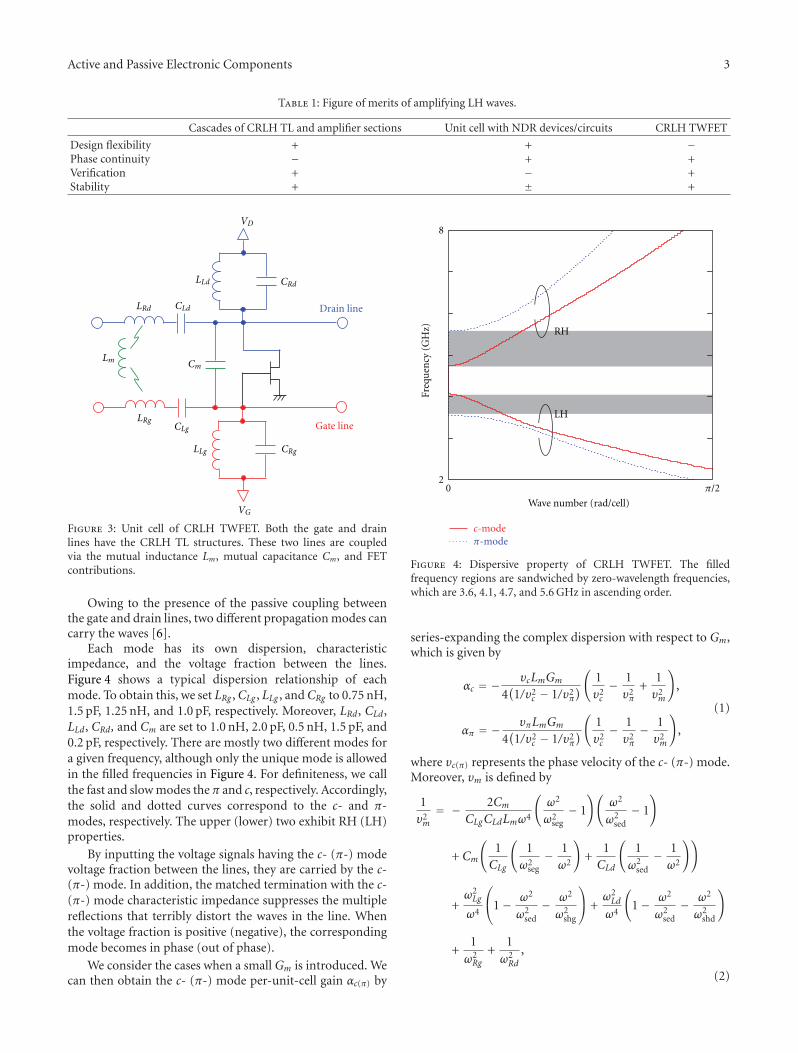
Figure 3: Unit cell of CRLH TWFET. Both the gate and drainlines have the CRLH TL structures. These two lines are coupledvia the mutual inductance Lm, mutual capacitance Cm, and FETcontributions.
Owing to the presence of the passive coupling betweenthe gate and drain lines, two different propagation modes cancarry the waves [6].
Each mode has its own dispersion, characteristicimpedance, and the voltage fraction between the lines.Figure 4 shows a typical dispersion relationship of eachmode. To obtain this, we set LRg ,CLg , LLg , andCRg to 0.75 nH,1.5 pF, 1.25 nH, and 1.0 pF, respectively. Moreover, LRd, CLd,LLd, CRd, and Cm are set to 1.0 nH, 2.0 pF, 0.5 nH, 1.5 pF, and0.2 pF, respectively. There are mostly two different modes fora given frequency, although only the unique mode is allowedin the filled frequencies in Figure 4. For definiteness, we callthe fast and slow modes the π and c, respectively. Accordingly,the solid and dotted curves correspond to the c- and π-modes, respectively. The upper (lower) two exhibit RH (LH)properties.
By inputting the voltage signals having the c- (π-) modevoltage fraction between the lines, they are carried by the c-(π-) mode. In addition, the matched termination with the c-(π-) mode characteristic impedance suppresses the multiplereflections that terribly distort the waves in the line. Whenthe voltage fraction is positive (negative), the correspondingmode becomes in phase (out of phase).
We consider the cases when a small Gm is introduced. Wecan then obtain the c- (π-) mode per-unit-cell gain αc(π) by
Wave number (rad/cell)
0 π/22
8
Freq
uen
cy (
GH
z) RH
LH
c-modeπ-mode
Figure 4: Dispersive property of CRLH TWFET. The filledfrequency regions are sandwiched by zero-wavelength frequencies,which are 3.6, 4.1, 4.7, and 5.6 GHz in ascending order.
series-expanding the complex dispersion with respect to Gm,which is given by
αc = − υcLmGm
4(1/υ2
c − 1/υ2π
)
(1υ2c− 1
υ2π
+1υ2m
)
,
απ = − υπLmGm
4(1/υ2
c − 1/υ2π
)
(1υ2c− 1
υ2π− 1
υ2m
)
,
(1)
where υc(π) represents the phase velocity of the c- (π-) mode.Moreover, υm is defined by
1υ2m= − 2Cm
CLgCLdLmω4
(ω2
ω2seg− 1
)(ω2
ω2sed− 1
)
+ Cm
(1CLg
(1
ω2seg− 1
ω2
)
+1CLd
(1
ω2sed− 1
ω2
))
+ω2Lg
ω4
⎛
⎝1− ω2
ω2sed− ω2
ω2shg
⎞
⎠ +ω2Ld
ω4
(
1− ω2
ω2sed− ω2
ω2shd
)
+1ω2Rg
+1
ω2Rd
,
(2)

4 Active and Passive Electronic Components
0.01
−0.04
Per-
un
it-c
ell g
ain
(1/
cell)
2 3.8Frequency (GHz)
c-mode
π-mode
Cu
toff
ofπ
-mod
e
Figure 5: Per-unit-cell gain for LH frequencies. The solid anddashed curves represent the π- and c-modes, respectively. The filledregion corresponds to amplification.
where ωRg = 1/(LRgCRg)1/2, ωRd = 1/(LRdCRd)1/2, ωLg =1/(LLgCLg)1/2, ωLd = 1/(LLdCLd)1/2, ωseg = 1/(LRgCLg)1/2,
ωsed = 1/(LRdCLd)1/2, ωshg = 1/(LLgCRg)1/2, and ωshd =1/(LLdCRd)1/2. Note that υm can become imaginary forfrequencies for which the RHS of (3) becomes negative.Moreover, (3) becomes singular for Lm = 0. In such asituation, αc(π) should be written as
αc = −υcCmGm
(1− ω2/ω2
sed
)(1− ω2/ω2
seg
)
2ω4CLgCLd(1/υ2
c − 1/υ2π
) , (3)
απ = −υπCmGm
(1− ω2/ω2
sed
)(1− ω2/ω2
seg
)
2ω4CLgCLd(1/υ2
c − 1/υ2π
) . (4)
In the above, αc(π) is defined to be negative for amplifyingRH waves. Correspondingly, the amplitude of the waveincreases if αc(π) becomes positive for LH waves, because thephase velocity has the opposite sign from the group velocity.By definitions, υπ is always greater than υc; therefore, αcαπ <0 for any frequencies if Lm is negligible. It is concludedthat one of the two modes can be uniquely amplified. Morespecifically, the c- (π-) mode can be uniquely amplified forLH (RH) waves if ω < ωsel or ω > ωseu, where ωseu =max(ωseg,ωsed) and ωsel = min(ωseg,ωsed). On the otherhand, the c- (π-) mode can be uniquely amplified for RH(LH) waves if ωsel < ω < ωseu.
By the introduction of any small but finite resistanceR, we obtain the form αc,π = pc,πGm + qc,πR with somecoefficients pc,π and qc,π for complex dispersion. Irrespectiveof qc,π , only one of the two modes is possibly amplified, ifpc pπ < 0. Thus, the key criteria that a CRLH TWFET can bedesigned to satisfy the condition for the unique mode to beamplified are equally valuable even with any loss or leakage.
Cu
toff
ofπ
-mod
e
Cu
toff
ofc-
mod
e
0.02
−0.01
Per-
un
it-c
ell g
ain
(1/
cell)
74.5
Frequency (GHz)
Figure 6: Per-unit-cell gain for RH frequencies. The solid anddashed curves represent the π- and c-modes, respectively. The filledregion corresponds to amplification.
In general, the resistance becomes larger for higherfrequencies. It tends to reach a saturated value. Insteadof modelling this frequency dependence, we employ thesaturated resistance for all the frequencies for overestimat-ing. We assigned the values of parasitic resistance to beproportional to the inductance, such that the resistance for1.0-nH inductor becomes 0.15Ω. By adding the linearizedcontribution of resistances in per-unit-cell gain, we obtainFigures 5 and 6, setting Gm to 2.0 mS. Figure 5 showsthe per-unit-cell gain for low frequencies correspondingto the LH branches. The amplified waves are expectedonly for the π-mode at the frequencies between 3.0 and3.3 GHz. The gain becomes maximal at 3.2 GHz, where thediscrepancy between υc and υπ becomes minimal. Figure 6is for high frequencies corresponding to the RH branches.The amplified waves are expected only for the c-mode at thefrequencies greater than 4.95 GHz.
4. Numerical Simulation of Test Line
Recently, we experimentally characterized a CRLH TWFETusing discrete components on a breadboard [7]. We built a90-section device. For convenience, all the series inductanceswere eliminated. As a result, the test line exhibited LHproperty for all the frequencies allowed to travel. The tran-sistors used were Toshiba 2SK30A, whose typical thresholdvoltage was −1.8 V. The inductors and capacitors wereimplemented using the TDK SPT0406 series and the TDKFK series, respectively. The values of CLg , CRg , CLd, CRd, andCm were set to 470, 47, 470, 470, and 47 pF, respectively.Moreover, the values of LLg and LLd were set to 10.0 and4.7 μH, respectively. The gate and drain lines were fed by theenvelope pulses generated by an NF WF1974 two-channelfunction generator. The waveforms were detected by Agilent

Active and Passive Electronic Components 5
n = 40
n = 10
100 mV
Vol
tage
Time (3 μs/div)
(a)
n = 10
100 mV
Vol
tage
Time (3 μs/div)
n = 40
(b)
Figure 7: Time-domain waveforms in test CRLH TWFET. (a)Measured and (b) calculated ones for the π-mode envelope pulses.
10073C passive probes and monitored in the time domainby using an Agilent DSO90254A oscilloscope. Through themeasurements, we found that the π-mode gains amplitudes,while the c-mode loses them. Moreover, when the test lineis terminated with the π-mode characteristic impedance, themultiple reflections of waves could be effectively suppressed.
To reinforce these observations, we simulate the mea-sured results by solving the transmission equations of thetest line using finite-difference time-domain method. Theequations are given by
LRgd2Indt2 + Lm
d2Jndt2
= − InCLg
− RgdIndt
− d
dt(Vn −Vn−1),
Time (3 μs/div)
n = 5
n = 10
50 mV
Vol
tage
(a)
Time (3 μs/div)
n = 5
n = 10
50 mV
Vol
tage
(b)
Figure 8: Time-domain waveforms in test CRLH TWFET. (a)Measured and (b) calculated ones for the c-mode envelope pulses.
LRdd2Jndt2 + Lm
d2Indt2
= − JnCLd
− RddJndt
− d
dt(Wn −Wn−1),
Wn −VD
LLd
=(d
dt+Rin,d
LLd
)(−(CRd + Cm)
dWn
dt
+CmdVn
dt+ Jn − Jn+1 − Ids(Vn)
),
Vn −VG
LLg=(d
dt+Rin,g
LLg
)
×(−(CRg + Cm
)dVn
dt+ In − In+1Cm
dWn
dt
),
(5)
6 Active and Passive Electronic Components
NumericalMeasured
0.04
−0.022 3
Frequency (MHz)
Per-
un
it-c
ell g
ain
(1/
cell)
0
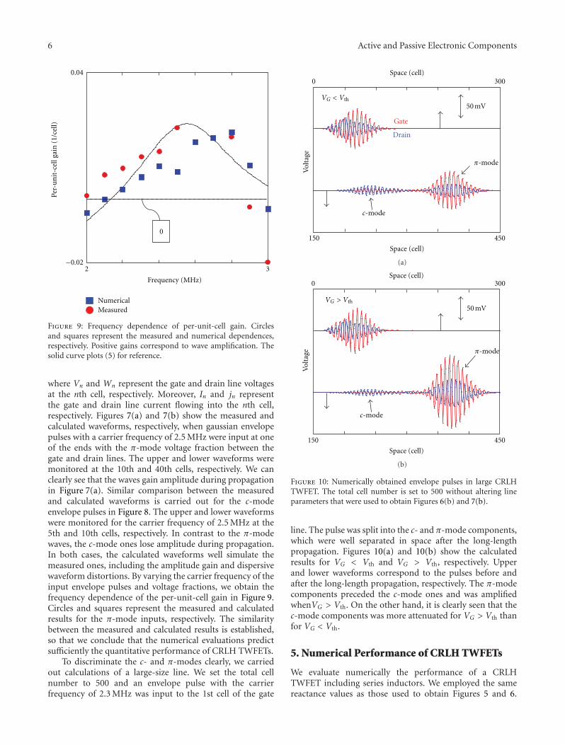
Figure 9: Frequency dependence of per-unit-cell gain. Circlesand squares represent the measured and numerical dependences,respectively. Positive gains correspond to wave amplification. Thesolid curve plots (5) for reference.
where Vn and Wn represent the gate and drain line voltagesat the nth cell, respectively. Moreover, In and jn representthe gate and drain line current flowing into the nth cell,respectively. Figures 7(a) and 7(b) show the measured andcalculated waveforms, respectively, when gaussian envelopepulses with a carrier frequency of 2.5 MHz were input at oneof the ends with the π-mode voltage fraction between thegate and drain lines. The upper and lower waveforms weremonitored at the 10th and 40th cells, respectively. We canclearly see that the waves gain amplitude during propagationin Figure 7(a). Similar comparison between the measuredand calculated waveforms is carried out for the c-modeenvelope pulses in Figure 8. The upper and lower waveformswere monitored for the carrier frequency of 2.5 MHz at the5th and 10th cells, respectively. In contrast to the π-modewaves, the c-mode ones lose amplitude during propagation.In both cases, the calculated waveforms well simulate themeasured ones, including the amplitude gain and dispersivewaveform distortions. By varying the carrier frequency of theinput envelope pulses and voltage fractions, we obtain thefrequency dependence of the per-unit-cell gain in Figure 9.Circles and squares represent the measured and calculatedresults for the π-mode inputs, respectively. The similaritybetween the measured and calculated results is established,so that we conclude that the numerical evaluations predictsufficiently the quantitative performance of CRLH TWFETs.
To discriminate the c- and π-modes clearly, we carriedout calculations of a large-size line. We set the total cellnumber to 500 and an envelope pulse with the carrierfrequency of 2.3 MHz was input to the 1st cell of the gate
Space (cell)
Space (cell)0 300
150 450
Vol
tage
π-mode
c-mode
Gate
Drain
50 mVVG < Vth
(a)
Space (cell)
Space (cell)0 300
150 450
Vol
tage π-mode
c-mode
50 mVVG > Vth
(b)
Figure 10: Numerically obtained envelope pulses in large CRLHTWFET. The total cell number is set to 500 without altering lineparameters that were used to obtain Figures 6(b) and 7(b).
line. The pulse was split into the c- and π-mode components,which were well separated in space after the long-lengthpropagation. Figures 10(a) and 10(b) show the calculatedresults for VG < Vth and VG > Vth, respectively. Upperand lower waveforms correspond to the pulses before andafter the long-length propagation, respectively. The π-modecomponents preceded the c-mode ones and was amplifiedwhenVG > Vth. On the other hand, it is clearly seen that thec-mode components was more attenuated for VG > Vth thanfor VG < Vth.
5. Numerical Performance of CRLH TWFETs
We evaluate numerically the performance of a CRLHTWFET including series inductors. We employed the samereactance values as those used to obtain Figures 5 and 6.
Active and Passive Electronic Components 7
Vol
tage
Space (cell)
1 500
VG < Vth
VG > Vth
(a)
Vol
tage
1 500
Space (cell)
VG < Vth
VG > Vth
(b)
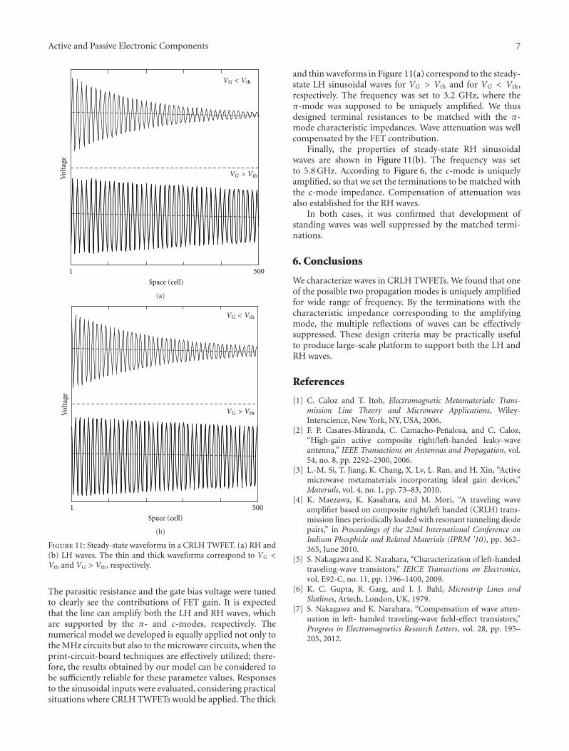
Figure 11: Steady-state waveforms in a CRLH TWFET. (a) RH and(b) LH waves. The thin and thick waveforms correspond to VG <Vth and VG > Vth, respectively.
The parasitic resistance and the gate bias voltage were tunedto clearly see the contributions of FET gain. It is expectedthat the line can amplify both the LH and RH waves, whichare supported by the π- and c-modes, respectively. Thenumerical model we developed is equally applied not only tothe MHz circuits but also to the microwave circuits, when theprint-circuit-board techniques are effectively utilized; there-fore, the results obtained by our model can be considered tobe sufficiently reliable for these parameter values. Responsesto the sinusoidal inputs were evaluated, considering practicalsituations where CRLH TWFETs would be applied. The thick
and thin waveforms in Figure 11(a) correspond to the steady-state LH sinusoidal waves for VG > Vth and for VG < Vth,respectively. The frequency was set to 3.2 GHz, where theπ-mode was supposed to be uniquely amplified. We thusdesigned terminal resistances to be matched with the π-mode characteristic impedances. Wave attenuation was wellcompensated by the FET contribution.
Finally, the properties of steady-state RH sinusoidalwaves are shown in Figure 11(b). The frequency was setto 5.8 GHz. According to Figure 6, the c-mode is uniquelyamplified, so that we set the terminations to be matched withthe c-mode impedance. Compensation of attenuation wasalso established for the RH waves.
In both cases, it was confirmed that development ofstanding waves was well suppressed by the matched termi-nations.
6. Conclusions
We characterize waves in CRLH TWFETs. We found that oneof the possible two propagation modes is uniquely amplifiedfor wide range of frequency. By the terminations with thecharacteristic impedance corresponding to the amplifyingmode, the multiple reflections of waves can be effectivelysuppressed. These design criteria may be practically usefulto produce large-scale platform to support both the LH andRH waves.
References
[1] C. Caloz and T. Itoh, Electromagnetic Metamaterials: Trans-mission Line Theory and Microwave Applications, Wiley-Interscience, New York, NY, USA, 2006.
[2] F. P. Casares-Miranda, C. Camacho-Penalosa, and C. Caloz,“High-gain active composite right/left-handed leaky-waveantenna,” IEEE Transactions on Antennas and Propagation, vol.54, no. 8, pp. 2292–2300, 2006.
[3] L.-M. Si, T. Jiang, K. Chang, X. Lv, L. Ran, and H. Xin, “Activemicrowave metamaterials incorporating ideal gain devices,”Materials, vol. 4, no. 1, pp. 73–83, 2010.
[4] K. Maezawa, K. Kasahara, and M. Mori, “A traveling waveamplifier based on composite right/left handed (CRLH) trans-mission lines periodically loaded with resonant tunneling diodepairs,” in Proceedings of the 22nd International Conference onIndium Phosphide and Related Materials (IPRM ’10), pp. 362–365, June 2010.
[5] S. Nakagawa and K. Narahara, “Characterization of left-handedtraveling-wave transistors,” IEICE Transactions on Electronics,vol. E92-C, no. 11, pp. 1396–1400, 2009.
[6] K. C. Gupta, R. Garg, and I. J. Bahl, Microstrip Lines andSlotlines, Artech, London, UK, 1979.
[7] S. Nakagawa and K. Narahara, “Compensation of wave atten-uation in left- handed traveling-wave field-effect transistors,”Progress in Electromagnetics Research Letters, vol. 28, pp. 195–205, 2012.

International Journal of
AerospaceEngineeringHindawi Publishing Corporationhttp://www.hindawi.com Volume 2010
RoboticsJournal of
Hindawi Publishing Corporationhttp://www.hindawi.com Volume 2014
Hindawi Publishing Corporationhttp://www.hindawi.com Volume 2014
Active and Passive Electronic Components
Control Scienceand Engineering
Journal of
Hindawi Publishing Corporationhttp://www.hindawi.com Volume 2014
International Journal of
RotatingMachinery
Hindawi Publishing Corporationhttp://www.hindawi.com Volume 2014
Hindawi Publishing Corporation http://www.hindawi.com
Journal ofEngineeringVolume 2014
Submit your manuscripts athttp://www.hindawi.com
VLSI Design
Hindawi Publishing Corporationhttp://www.hindawi.com Volume 2014
Hindawi Publishing Corporationhttp://www.hindawi.com Volume 2014
Shock and Vibration
Hindawi Publishing Corporationhttp://www.hindawi.com Volume 2014
Civil EngineeringAdvances in
Acoustics and VibrationAdvances in
Hindawi Publishing Corporationhttp://www.hindawi.com Volume 2014
Hindawi Publishing Corporationhttp://www.hindawi.com Volume 2014
Electrical and Computer Engineering
Journal of
Advances inOptoElectronics
Hindawi Publishing Corporation http://www.hindawi.com
Volume 2014
The Scientific World JournalHindawi Publishing Corporation http://www.hindawi.com Volume 2014
SensorsJournal of
Hindawi Publishing Corporationhttp://www.hindawi.com Volume 2014
Modelling & Simulation in EngineeringHindawi Publishing Corporation http://www.hindawi.com Volume 2014
Hindawi Publishing Corporationhttp://www.hindawi.com Volume 2014
Chemical EngineeringInternational Journal of Antennas and
Propagation
International Journal of
Hindawi Publishing Corporationhttp://www.hindawi.com Volume 2014
Hindawi Publishing Corporationhttp://www.hindawi.com Volume 2014
Navigation and Observation
International Journal of
Hindawi Publishing Corporationhttp://www.hindawi.com Volume 2014
DistributedSensor Networks
International Journal of