COMPOSITE WOOD-BASED BEAMS AND COLUMNS
33
EAD 130367-00-0304 December 2018 COMPOSITE WOOD-BASED BEAMS AND COLUMNS ©2020
Transcript of COMPOSITE WOOD-BASED BEAMS AND COLUMNS

EAD 130367-00-0304
December 2018
COMPOSITE WOOD-BASED BEAMS AND COLUMNS
©2020

European Assessment Document – EAD 130367-00-0304 2/33
©EOTA 2020
The reference title and language for this EAD is English. The applicable rules of copyright refer to the document elaborated in and
published by EOTA.
This European Assessment Document (EAD) has been developed taking into account up-to-date technical and scientific knowledge at the time of issue and is published in accordance with the relevant provisions of Regulation (EU) No 305/2011 as a basis for the preparation and issuing of European Technical Assessments (ETA).

European Assessment Document – EAD 130367-00-0304 3/33
©EOTA 2020
Contents
1 Scope of the EAD ..................................................................................................................... 4
1.1 Description of the construction product 4
1.2 Information on the intended use(s) of the construction product 6 Intended uses ................................................................................................................... 6 Working life / durability ...................................................................................................... 6
1.3 Specific terms used in this EAD 6 Height, width and length.................................................................................................... 6 Tapered ............................................................................................................................ 7 Effective strength or modulus of elasticity or rigidity ........................................................... 7 Glue bond specimen ......................................................................................................... 7
2 Essential characteristics and relevant assessment methods and criteria............................. 8
2.1 Essential characteristics of the product 8
2.2 Methods and criteria for assessing the performance of the product in relation to essential characteristics of the product 9
Mechanical resistance and stiffness in general .................................................................. 9 Bending strength and/or bending moment capacity (edgewise and flatwise) and size effect
parameter ........................................................................................................................11 Tension strength and/or tension capacity parallel to the product and size effect parameter
........................................................................................................................................11 Tension strength and/or tension capacity perpendicular to the product .............................12 Compression strength and/or compression capacity parallel to the product ......................12 Compression strength perpendicular to the product (edgewise and flatwise) and bearing
capacity ...........................................................................................................................12 Shear strength or shear capacity ......................................................................................13 Modulus of elasticity parallel to the grain and flexural rigidity ............................................13 Shear modulus and shear rigidity .....................................................................................13
Torsional shear capacity and rigidity ................................................................................14 Density of the wood based components ...........................................................................14 Creep and duration of the load .........................................................................................14 Dimensional stability ........................................................................................................14 Corrosion resistance of the product ..................................................................................14 Bonding quality and durability of bonding strength ............................................................15 Reaction to fire ................................................................................................................15 Resistance to fire .............................................................................................................16 Content, emission and/or release of dangerous substances .............................................17 Thermal conductivity ........................................................................................................17 Thermal inertia .................................................................................................................18 Natural Durability .............................................................................................................18
3 Assessment and verification of constancy of performance ..................................................19
3.1 System of assessment and verification of constancy of performance to be applied 19
3.2 Tasks of the manufacturer 19 Factory Production Control ..............................................................................................19
3.3 Tasks of the notified body 21
3.4 Special methods of control and testing used for the verification of constancy of performance 21
4 Reference documents .............................................................................................................22
ANNEX A - Test methods for composite wood-based beams and columns .....................................24

European Assessment Document – EAD 130367-00-0304 4/33
©EOTA 2020
1 SCOPE OF THE EAD
1.1 Description of the construction product
This EAD covers composite wood-based beams and columns with flange components consisting of a wood-based material. The web may also be metal. It includes, for example, adhesives, mechanical connections, reinforcement, fixing elements. Figure 1 shows examples of composite wood-based beams and columns used in building construction as structural members. Beams are primarily subjected to bending, shear and concentrated loads at the supports. Columns are primarily subjected to compressive forces in the axial direction, but also to transversal forces. The beams or columns may be single tapered or double tapered. This EAD only covers products which are not chemically treated (against decay, fire…).
A B
C

European Assessment Document – EAD 130367-00-0304 5/33
©EOTA 2020
A B C
Figure 1: Examples of beams, columns and their cross sections
Composite wood-based beams and columns are typically defined as slender and with low weight. Flanges and web/web bars are connected with adhesive bonded joints or mechanical joints.
Relationship with European harmonised technical specifications
The product is not covered by a harmonised European standard (hEN).
This EAD does not cover glued laminated timber, glued solid timber products, timber trusses, LVL beams and columns, wood-based stressed skin elements or metal lattice web beams and columns that are
covered by harmonised technical specifications1. Nor does it include timber formwork beams, which are outside the scope of the CPR.
Composite wood-based beams and columns consist of three parts: web, flange and adhesive/ connection, see also figure 1.
The products have predetermined sizes or they are individually specified on the customer's request for their works within the range of the predetermined sizes.
The characteristic values of density of the components can be considered representative for the product.
Concerning product packaging, transport, storage, maintenance, replacement and repair it is the responsibility of the manufacturer to undertake the appropriate measures and to advise his clients on the transport, storage, maintenance, replacement and repair of the product as he considers necessary.
It is assumed that the product will be installed according to the manufacturer’s instructions or (in absence of such instructions) according to the usual practice of the building professionals.
Relevant manufacturer’s stipulations having influence on the performance of the product covered by this European Assessment Document shall be considered for the determination of the performance and detailed in the ETA.
This EAD applies for products where the following flange and web materials and adhesives are used:
- Wood based flange and web materials according to hEN143742, hEN14080, hEN14081, hEN13986 or hEN15497
- Metal web components including their surface treatment according to their standards
1 Products where flatwise surfaces are glued together with edgewise surfaces are covered with EAD 140022-00-0304
“Prefabricated wood-based loadbearing stressed skin panels”, metal web beams and columns are covered with EAD
130031-00-0304 and Glued laminated LVL in EAD 130337-00-0304 2 All undated references to standards or to EADs in this Chapter are to be understood as references to the dated
versions listed in clause 4.

European Assessment Document – EAD 130367-00-0304 6/33
©EOTA 2020
- Fasteners according to hEN14592 or hEN14545 - Adhesives type I according to EN 301, subclasses GP or GF, M or S - Adhesives type I according to EN 15425, subclasses GP or SP These adhesives shall fulfil the requirements in EN 14080
In case of finger jointed wooden flanges or webs the following adhesives are used:
- Adhesives type I according to EN 301, subclass FJ, M or S - Adhesives type I according to EN 15425, subclass FJ These adhesives shall fulfil the requirements in EN 15497.
1.2 Information on the intended use(s) of the construction product
Intended uses
Composite wood-based beams and columns are intended to be used as a structural element for load-bearing applications in buildings and civil engineering structures, for example: construction members or frame elements for walls, roofs, floors and trusses
The product is only intended to be used subject to static or quasi-static actions. In seismic areas the behaviour factor of composite wood-based beams and columns used for the design is limited to non-dissipative or low-dissipative structures (q ≤1,5), defined according to Eurocode 8 (EN 1998-1:2004 clauses 1.5.2 and 8.1.3 b).
Note: Products intended for higher class of dissipative structure need further assessment and are not covered by this EAD.
The products are intended to be used in service class 1 and 2 according to EN 1995-1-1.
Working life / durability
The assessment methods included or referred to in this EAD have been written based on the manufacturer’s request to take into account a working life of the composite wood-based beam or column for the intended use of 50 years when installed in the works. These provisions are based upon the current state of the art and the available knowledge and experience.
When assessing the product the intended use as foreseen by the manufacturer shall be taken into account. The real working life may be, in normal use conditions, considerably longer without major degradation
affecting the basic requirements for works3.
The indications given as to the working life of the construction product cannot be interpreted as a guarantee neither given by the product manufacturer or his representative nor by EOTA when drafting this EAD nor by the Technical Assessment Body issuing an ETA based on this EAD, but are regarded only as a means for expressing the expected economically reasonable working life of the product.
1.3 Specific terms used in this EAD
Height, width and length
In members loaded by bending, the cross sectional dimension "height" h is the dimension in the direction of the considered (vertical) external load and "width" w is the dimension perpendicular to that. In purely
3 The real working life of a product incorporated in a specific works depends on the environmental conditions to
which that works is subject, as well as on the particular conditions of the design, execution, use and maintenance of
that works. Therefore, it cannot be excluded that in certain cases the real working life of the product may also be
shorter than referred to above.

European Assessment Document – EAD 130367-00-0304 7/33
©EOTA 2020
axially loaded members, height and width are equivalent and height is defined as the larger dimension. "Length" L is the dimension perpendicular to the cross section.
Tapered
A member the height of which depends linearly on the length.
L
h
w
L
single tapered double tapered
Figure 2. Definition of single tapered and double tapered, height d, width w and length L.
Effective strength or modulus of elasticity or rigidity
A strength, modulus of elasticity or modulus or rigidity value calculated for the whole cross section.
Glue bond specimen
Specimen cut from product for bonding quality tests.

European Assessment Document – EAD 130367-00-0304 8/33
©EOTA 2020
2 ESSENTIAL CHARACTERISTICS AND RELEVANT ASSESSMENT METHODS
AND CRITERIA
2.1 Essential characteristics of the product
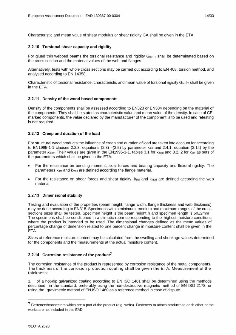
Table 2.1 shows how the performance of composite wood-based beams and columns are assessed in relation to the essential characteristics.
Table 2.1 Essential characteristics of the product and methods and criteria for assessing the performance of the product in relation
to those essential characteristics
No Essential characteristic Assessment
method
Type of expression of product performance
(level, class, description)
Basic Works Requirement 1: Mechanical resistance and stability
1. Bending strength and/or bending moment capacity (edgewise and flatwise) and size effect parameter (edgewise and flatwise)
2.2.2 Description, level
2. Tension strength and/or tension capacity parallel to the product and size effect parameter
2.2.3 Description, level
3. Tension strength and/or capacity perpendicular to the product
2.2.4 Description, level
4. Compression strength and/or capacity parallel to the product
2.2.5 Description, level
5. Compression strength perpendicular to the product (edgewise and flatwise) and/or bearing capacity
2.2.6 Description, level
6. Shear strength and/or capacity (edgewise and flatwise) and size effect parameter (flatwise)
2.2.7 Description, level
7. Modulus of elasticity parallel to the grain 2.2.8 Description, level
8. Shear modulus (edgewise and flatwise) 2.2.9 Description, level
9. Torsional shear capacity and rigidity 2.2.10 Description, level
10. Density 2.2.11 Level
11. Creep and duration of the load 2.2.12 Description, level
12. Dimensional stability 2.2.13 Description, level
13. Corrosion resistance of metal fasteners and other connectors
2.2.14 Description
14. Bonding quality and durability of bonding strength 2.2.15 Description, level
Basic Works Requirement 2: Safety in case of fire
15. Reaction to fire 2.2.16 Class
16. Resistance to fire 2.2.17 Description, level
European Assessment Document – EAD 130367-00-0304 9/33
©EOTA 2020
No Essential characteristic Assessment
method
Type of expression of product performance
(level, class, description)
Basic Works Requirement 3: Hygiene, health and the environment
17. Content, emission and/or release of dangerous substances
2.2.18 Class
Basic Works Requirement 6: Energy economy and heat retention
18. Thermal conductivity 2.2.19 Description, level
19. Thermal inertia 2.2.20 Description, level
Aspects of durability
20. Natural Durability 2.2.21 Description, level
2.2 Methods and criteria for assessing the performance of the product in relation to essential characteristics of the product
This chapter is intended to provide instructions for TABs. Therefore, the use of wordings such as “shall be stated in the ETA” or “it has to be given in the ETA” shall be understood only as such instructions for TABs on how results of assessments shall be presented in the ETA. Such wordings do not impose any obligations for the manufacturer and the TAB shall not carry out the assessment of the performance in relation to a given essential characteristic when the manufacturer does not wish to declare this performance in the Declaration of Performance.
Mechanical resistance and stiffness in general
Performances of essential characteristics shall be established in the following ways or by the combination of thereof:
- Calculation based on Eurocodes and ordinary statics
- Testing or
- Calculation assisted by testing, where the calculation method is modified from those given in Eurocodes.
Calculation is an economical way to establish the performance of characteristics, but it may give conservative results. Testing or calculation assisted by testing alternatives are more expensive to perform, but they may give advantages in end results.
Further, if the manufacturer predetermines cross sections, it is possible to define effective (characteristic) strength values (or resistances) for the cross sections.
If the manufacturer does not define predetermined cross sections, it is possible to present a calculation method (or software) of the product that utilizes the strength and stiffness values of the components.
TAB shall review the calculation method and its boundary conditions. Relevant information shall be presented in the ETA.
2.2.1.1 . Calculation of mechanical resistance and stiffness
In general, the calculation method is suitable when the strength and stiffness properties of the webs, flanges and jointing method are well known and documented in their declarations of performance. Furthermore, the theoretical model used to estimate the mechanical resistance and stability shall be well established. EN 1995-1-1:2004; A1 A2 AC 2014 assumes linear elastic behaviour of the timber materials

European Assessment Document – EAD 130367-00-0304 10/33
©EOTA 2020
and the performance of other composite cross sections is calculated on the basis of the strength and stiffness properties of the components (clauses 3.1.2 and 9.1). When the properties are not defined in DoPs, the methods in chapters 2.2.1.2 or 2.2.1.3 shall be used.
NOTE: For some products the material for the flanges is graded before it is re-sawn to flange components. In such cases the mechanical properties of the flanges shall be considered separately before using the calculation model.
NOTE: For most products the flanges or webs are lengthways jointed (for example finger jointed). In such cases the mechanical properties of the flanges, including finger joints, and webs shall be considered separately before using the calculation model.
The composite effect of glued composite wood-based beams and columns only relies on the adhesive bond between the components. Therefore, the performance of the beams and columns is calculated from the strength and stiffness properties of the components as for composite beams. For the purpose, the strength and stiffness values of the component manufacturer's declaration of performance including the source shall be given in the ETA. If several types of components are used, all of them shall be specified. In cases where the width of the product is large, the effective width shall be taken into account as provided for in EN 1995-1-1,clause 9.1.2 for glued thin-flanged beams where the flange is representative wood based panel material.
The manufacturing method of composite wood-based beams and column may involve sanding or planing of the components. When relevant, the effect of sanding or planing to strength properties shall be taken into account in the assessment.
EN 1995-1-1 shall also be applied in the calculation of the details of the structural members made of
composite wood-based beams and column. Partial factor M for material properties and resistance for components given in EN 1995-1-1 shall be used in absence of nationally determined parameters. Reference to this shall be given in the ETA.
Size effect of composite wood-based beams and column shall be taken into account.
• For glued thin-webbed beams the size effect shall be taken into account in the tension and bending moment resistance by reduction of the tension strength of flange on the tensile side of the cross section EN1995-1-1, clause 9.1.1, equation (9.4). In the case of LVL flanges the size effect factor kl of EN 1995-1-1:2004 clause 3.4 is used. For other flange materials the size effect factor shall be assessed according to 2.2.3.
• In other cases the size effect shall be taken into account according to the material of the components in stronger and weaker direction of the products unless proven otherwise.
2.2.1.2 Testing
When a theoretical model and the material values of the components are not utilised, the characteristic values of the mechanical properties of the product can be determined directly from tests specified later on. Moisture content and density of the specimens shall be determined, as well as the specification of the components.
When the properties of the components are not well known and documented, then the number of specimens shall not be less than 30 for each type, grade and size of the product to be tested. Characteristic strength values shall be calculated as provided for in EN 14358, lognormal or normal distribution can be assumed.
Suitable tests based on the methods given in the section "Test methods" described in the Annex A , shall be considered separately for each product to determine the following properties:
• Bending
• Compression parallel to grain direction of the flanges
• Compression in perpendicular to grain direction of the flanges (Bearing / support reaction)
• Combination of the above
• Shear
2.2.1.3 Calculation assisted by testing
It is possible to define and use a specific calculation system for the performance of a product, when the

European Assessment Document – EAD 130367-00-0304 11/33
©EOTA 2020
system has been verified through the methods described in EN 1990, clause 5 and Annex D. In general,
the calculation assisted by testing can be used when
• Assessing fastener related performances (as part of the product)
• The results of tests show a difference compared to the calculation according to 2.2.1.1 due to
performance characteristics of components given in a conservative way in their DoPs. In this case
correlation factors or adapted values for the components performance can be derived from
calculation assisted by testing. Tests for the components according to their respective standards
are advised to determine, which product characteristics differ in value from those given in the DoP
of the component.
• A specific calculation model other than those described in 2.2.1.1 shall be used. In this case testing
is needed both for the components (if their properties are used in the calculation) and the beams
or columns to validate the results of calculation according to that model.
Regarding the number of specimens to be tested, see EN 1990, clause 5 and Annex D. It is recommended
that at least 3 sets of 4 tests are made for each characteristic performance value to be determined 4 . The number of specimens used and the results shall be stated in the ETA.
Bending strength and/or bending moment capacity (edgewise and flatwise) and size effect parameter
Calculation: Bending strength edgewise and flatwise of the product can be derived from those for the components. The calculated stress values must not exceed the strength of the components in any point of the cross section. Principle of the stress distribution is in EN1995-1-1, Figure 9.1. Effective bending strength or bending moment resistance for a given whole cross section can thus be calculated. It is usually user friendly to define bending moment resistance of the cross section. When bending moment resistance is calculated for the whole cross section, the criteria of tension and compression strengths in the middle and at the edge of the flange according to EN1995-1-1, clause 9.1.1 shall be taken into consideration. The size effect shall be taken into consideration in design value of tensile strength in the EN1995-1-1, clause 9.1.1, equation (9.4)
Testing or calculation assisted by testing: Tests with whole cross sections shall be carried out according to the principle of EN 408 and analysed according to EN 14358. Further information for testing is also given in the section A.2.2 of Annex A. Tests can be made simultaneously with modulus of elasticity tests; the test may be interrupted for removing the deformation measurement equipment at about 60 % the ultimate load.
Size effect shall be calculated from the bending test results of the product for both bending strength edgewise and flatwise. It is possible to determine the value for the size effect factor from the tests with whole cross sections (e.g. small, medium, and large). The results may be analysed by curve fitting equation
ln (f) = s ln (1/h) + C (Eq. 1)
in the results. s is the size effect, f is the strength, h is the height of the specimen and C is constant derived from the test results so that the equation gives safe side results for the height range of the product.
Characteristic bending strength values as well as size effect parameters and reference heights or bending moment resistance of the cross sections shall be given in the ETA and clarified in form of equations. Alternatively bending moment resistance of the cross sections shall be given in the ETA.
Tension strength and/or tension capacity parallel to the product and size effect parameter
Tension strength parallel to the product can be derived from the flange components. In case of several types of components in the same product, stress distribution of the cross section shall be calculated
4 For small number of specimens, the calculation methods in EN 14358 imply a punishment in accordance with
EN1990. In case of normal distribution and the minimum standard deviation of 0,05 assumed, the same mean value
gives for 5 specimens a characteristic strength 0,98 times the one for 10 specimens, while for 15 specimens the
characteristic strength would be 1,01 times the one for 10 specimens. This effect is larger if the standard deviation is
larger, what it often is for small number of specimens.

European Assessment Document – EAD 130367-00-0304 12/33
©EOTA 2020
assuming linear elasticity. The calculated stress values must not exceed the strength (or yield strength of metal) of the components in any point of the cross section. Tension resistance Rk for a given whole cross section can thus be calculated as
Rk, tension = ft,0,k • Aeff, (Eq. 2)
where ft,0,k is characteristic tension strength of flange components
Aeff is effective cross section area of flanges. In case of several types of flanges, their share of the effective cross section area is calculated according to their modulus’s of elasticity.
Alternatively, tests with whole cross sections may be carried out according to EN 408 and analysed according to EN 14358, but it is not practical, since it need large gripping devices.
For LVL flange components, size effect shall be calculated from the bending test results of the components for bending strength edgewise. The size effect in tension is defined in EN1995-1-1, clause 3.4. to be half of the size effect for bending edgewise. For other flange materials, the size effect factor, shall be tested with different flange lengths(e.g. small, medium, large) and analysed analogically to the bending strength.
Characteristic tension strength or resistance as well as size effect parameter and reference length shall be given in the ETA, and clarified in form of equations.
Tension strength and/or tension capacity perpendicular to the product
Tension resistance perpendicular to the product edgewise is the minimum one of the flanges, webs or joints. The calculated stress values must not exceed the strength in any point of the cross section.
When the strength of the connections between the components are not known, they shall be tested. The tests with whole cross sections may be carried out according to the principle of EN 408 clause 16 with specimen’s size adjusted for the product so that the whole cross section is tension loaded and analysed according to EN 14358.
Characteristic tension resistance or strength shall be given in the ETA.
Compression strength and/or compression capacity parallel to the product
Compression strength parallel to the product is the same as the one for flanges5. In case of several types of components in the same product, stress distribution of the cross section shall be calculated assuming linear elasticity. The calculated stress values must not exceed the strength of the components in any point of the cross section. In the case of mechanically jointed and glued columns, the instructions in EN1995-1-1, clause 9.1.4 and annex C shall be taken into account. Effective compression strength for a given whole cross section or compression resistance to compressive axial forces can thus be calculated, if wanted.
Alternatively, tests with whole cross sections may be carried out according to EN 408, clause 15 and analysed according to EN 14358. Further information for testing is given in the sections A.2..5 of Annex A. Transverse load H is optional in the test.. For the use in service class 2 conditions, the test results from service class 1 conditions of products with flanges out of solid timber, glulam or LVL shall be divided by 1,2. Alternatively, the specimens shall be conditioned in climate corresponding to service class 2 conditions for testing.
Characteristic compression strength parallel to the product or compression resistance to compressive axial forces in service class 1 and 2 conditions shall be given in the ETA.
Compression strength perpendicular to the product (edgewise and flatwise) and bearing capacity
The bearing capacity of glued thin webbed beams is dependent on the cross section geometry, flange and web materials and the connection between them. Therefore the testing or calculation assisted by testing is
5 Under the revision EN 14374, different strength values are specified for service classes 1 and 2.

European Assessment Document – EAD 130367-00-0304 13/33
©EOTA 2020
usually required to determine the edgewise bearing capacity of the joists. The test method is specified in Annex, Section A.2.3
Bearing capacity assessment of type A beams of figure 1 require testing according to Annex A, Section A.2.3. For the type B and C beams of figure 1, where so-called knifing failure mode of a thin web penetrating into the flange is not critical, the compression strength perpendicular to the product edgewise and flatwise are the same as those for the components. In case of several types of components in the same product, edgewise stress distribution of the cross section shall be calculated assuming linear elasticity. For flatwise compression strength, the strength of the outermost component applies. The calculation is only valid, if the calculated stress values do not exceed the strength of the components in any point of the cross section. Effective compression strength for a given whole cross section can thus be calculated. Alternatively, tests may be carried out according to EN 408 and analysed according to EN 14358.
Characteristic compression strength values perpendicular to the grain or bearing capacity of the cross sections shall be given in the ETA.
Shear strength or shear capacity
When the components of glued thin webbed beams are continuous, the shear capacity can be calculated based on the instructions in clause 9.1.1 of EN 1995-1-1:2004. In the case of mechanically jointed beams, the instructions in EN1995-1-1, clause 9.1.3 and annex B shall be taken into account. The shear capacity is dependent on the cross section geometry, flange and web materials and the connection between them. Therefore testing or calculation assisted by testing is required to determine the shear capacity of the joists. Test method is specified in section A.2.4 of Annex A. Strength reducing characteristics e.g. joints between web components and holes in web shall be taken into consideration. Tests can be made simultaneously with shear modulus tests; the test may be interrupted for removing the deformation measurement equipment at about 60 % the ultimate load
For the types B and C beams a size effect of the shear strength flatwise direction shall be calculated from the shear test results of the flanges. Tests with whole cross sections (e.g. small, medium, large) can be done and analysed analogically to bending strength to determine the size effect factor.
Characteristic shear strength values as well as size effect parameter and reference height for flatwise shear shall be given in the ETA, and clarified in form of equations. Alternatively, the cross sections’ shear capacity (= resistance to shear forces) shall be given in the ETA.
Modulus of elasticity parallel to the grain and flexural rigidity
Stress distribution of the cross section of glued thin webbed beams shall be calculated assuming linear
elasticity and modulus of elasticity values of the components are used in the calculation6. Effective modulus of elasticity or flexural rigidity EI for a given cross section can thus be calculated.
Alternatively, tests with whole cross sections may be carried out according to EN 408 and analysed according to EN 14358. Tests can be made simultaneously with bending strength tests.
Characteristic and mean values of modulus of elasticity or flexural rigidity EI shall be given in the ETA.
Shear modulus and shear rigidity
For glued thin webbed beams shear rigidity GA is defined based on the cross section area and material values of the web.
Alternatively, tests with whole cross sections may be carried out according to EN 408, clause 11.2 shear field test method, and analysed according to EN 14358. Tests can be made simultaneously with shear strength or bending strength tests.
6 Observe that EN 14374 defines modulus of elasticity edgewise and flatwise as local modulus of elasticity from
edgewise bending tests according to EN 408.
European Assessment Document – EAD 130367-00-0304 14/33
©EOTA 2020
Characteristic and mean value of shear modulus or shear rigidity GA shall be given in the ETA.
Torsional shear capacity and rigidity
For glued thin webbed beams the torsional resistance and rigidity Gtor IT shall be determinated based on the cross section and the material values of the web and flanges.
Alternatively, tests with whole cross sections may be carried out according to EN 408, torsion method, and analysed according to EN 14358.
Characteristic of torsional resistance, characteristic and mean value of torsional rigidity Gtor IT shall be given in the ETA.
Density of the wood based components
Density of the components shall be assessed according to EN323 or EN384 depending on the material of the components. They shall be stated as characteristic value and mean value of the density. In case of CE-marked components, the value declared by the manufacturer of the component is to be used and retesting is not required.
Creep and duration of the load
For structural wood products the influence of creep and duration of load are taken into account for according to EN1995-1-1 clauses 2.2.3, equations (2.3) –(2.5) by parameter kdef and 2.4.1, equation (2.14) by the parameter kmod. Their values are given in the EN1995-1-1, tables 3.1 for kmod and 3.2. 2 for kdef as sets of the parameters which shall be given in the ETA:
• For the resistance on bending moment, axial forces and bearing capacity and flexural rigidity. The parameters kdef and kmod are defined according the flange material.
• For the resistance on shear forces and shear rigidity. kdef and kmod are defined according the web material
Dimensional stability
Testing and evaluation of the properties (beam height, flange width, flange thickness and web thickness) may be done according to EN318. Specimens within minimum, medium and maximum ranges of the cross sections sizes shall be tested. Specimen height is the beam height h and specimen length is 50±2mm . The specimens shall be conditioned in a climatic room corresponding to the highest moisture conditions where the product is intended to be used. The dimensional changes defined as the mean values of percentage change of dimension related to one percent change in moisture content shall be given in the ETA.
Sizes at reference moisture content may be calculated from the swelling and shrinkage values determined for the components and the measurements at the actual moisture content.
Corrosion resistance of the product7
The corrosion resistance of the product is represented by corrosion resistance of the metal components. The thickness of the corrosion protection coating shall be given the ETA. Measurement of the thickness:
1. of a hot-dip galvanized coating according to EN ISO 1461 shall be determined using the methods described in the standard, preferably using the non-destructive magnetic method of EN ISO 2178, or using the gravimetric method of EN ISO 1460 as a reference method in case of dispute.
7 Fasteners/connectors which are a part of the product (e.g. webs). Fasteners to attach products to each other or the
works are not included in this EAD.

European Assessment Document – EAD 130367-00-0304 15/33
©EOTA 2020
2. of a coating of a hot-dip zinc coated sheet according to EN 10346 shall be determined using the methods described in Annex A of the standard.
3. of electroplated zinc coating according to EN ISO 2081 shall be determined using the methods described in the standard, or using EN ISO 2177 as a reference method in case of dispute.
4. of an electroplated cadmium coating according to EN ISO 2082 is determined using the methods described in the standard.
5. for dowel type fasteners the method is given in prEN14592, annex C
It should be noted that standards for galvanized and electroplated coatings express mass/unit area of coatings with respect to the surface area, and standards for hot-dip coated sheet express mass/unit area with respect to the area of the sheet (i.e. the area of a sheet represents half the area of its sur- face).
The specification for metal fasteners and other structural connectors shall be examined to determine whether any risk of bimetallic corrosion exists and any evidence of monitored atmospheric exposure tests to EN ISO 7441 shall be evaluated
An assessment shall be made as to the risks of corrosion arising from any acidic timber species proposed for use in the composite wood-based beams and columns with the metal fasteners and other structural connectors.
In case of CE-marked components, the value declared by the manufacturer of the component is to be used and retesting is not required.
Bonding quality and durability of bonding strength
For glued thin webbed beams (type A) a shear test method described in EN 13377, D.4 can be used in the assessment of bonding quality. When the product is assessed for use class 1 and 2 conditions, wet-dry cycles are not required.
For the type B and C beams the bonding quality shall be determined as for LVL according to EN 14374, annex B (cleaving test) or as for glulam according to EN 14080, annex D (shear test). The glue bond between the components shall be equally strong as the components themselves. Thickness of the glue line as well as the amount of wood failure shall be measured.
The requirements shall be formulated according to the adhesive and components that have been used. E.g. if the drill core test like EN 14080 Fig D7 a) is used, the following criteria apply:
- The measured glue line thickness on the surface of the drill core shall fulfil the requirement for the adhesive used
- The strength measured shall exceed the one for components measured by the same method
- The amount of wood failure shall normally be more than 80 %. If the strength of the glue line is 1,2 times the one of the components, then the amount of wood failure may be smaller.
For the assessment, bonding quality shall be tested for each intended combination of manufacturing method, adhesive, components and product type. The specimen product for bonding tests shall reflect the largest intended product size implying worst case from the manufacturing point of view. The ETA shall have a size limit based on that specimen product size, facilities and production methods.
For the assessment, bonding test specimens shall be taken of the specimen product from every glue line
and in both ends and at least in third points or one per 3 m ( 4 per glue line). If the product is manufactured in a hydraulic press, the specimens shall be taken in the middle between each cylinder. Any other critical points shall be taken into account in sampling.
Reaction to fire
The web/flange materials of structural timber are considered to satisfy the requirements for performance
class D-s2,d0 of the characteristic reaction to fire in accordance with the EC Decision 2003/593/EC as
amended without the need for testing on the basis of it fulfilling the conditions set out in that Decision and
its intended use being covered by that Decision.

European Assessment Document – EAD 130367-00-0304 16/33
©EOTA 2020
Therefore the performance of the web/flange materials of structural timber is D-s2,d0.
The web/flange materials of glulam are considered to satisfy the requirements for performance class D-
s2,d0 of the characteristic reaction to fire in accordance with the EC Decision 2005/610/EC as amended
without the need for testing on the basis of it fulfilling the conditions set out in that Decision and its intended
use being covered by that Decision.
Therefore the performance of the web/flange materials of glulam is D-s2,d0.
The web/flange materials of LVL and CLT are considered to satisfy the requirements for performance class
D-s2,d0 of the characteristic reaction to fire in accordance with the EC Decision 2017/2293/EC as amended
without the need for testing on the basis of it fulfilling the conditions set out in that Decision and its intended
use being covered by that Decision.
Therefore the performance of the web/flange materials of LVL and CLT is D-s2,d0.
The web/flange materials of wood-based materials are considered to satisfy the requirements for performance class B-s1,d0, D-s2,d0, D-s2,d1 or D-s2,d2 of the characteristic reaction to fire in accordance with the EC Decision 2003/43/EC as amended without the need for testing on the basis of it fulfilling the conditions set out in that Decision and its intended use being covered by that Decision.
Therefore the performance of the web/flange materials of wood-based materials is B-s1,d0, D-s2,d0, D-s2,d1 or D-s2,d2.
The fasteners are considered to satisfy the requirements for performance class A1 of the characteristic
reaction to fire in accordance with the EC Decision 96/603/EC as amended without the need for testing on
the basis of it fulfilling the conditions set out in that Decision and its intended use being covered by that
Decision.
Therefore the performance of the metal members is A1.
When the components / the product do not meet the provisions of the aforementioned EC Decisions or when a higher classification is sought, testing shall be done using the procedures/test method(s) according to EN 13501-1 and relevant for the corresponding reaction to fire class. The product shall be classified according to Commission Delegated Regulation (EU) No 2016/364.
Resistance to fire
Load-bearing performance (class R) can be determined in accordance with EN 1995-1-2 when the beam or column is made only from wood-based materials with known charring rates as defined in EN 1995-1-2 as a part of design of works. Charring rate of the components according to EN 1995-1-2 shall be given in the
ETA.8. Alternatively, R for the beams and columns, may be determined by testing as specified in EN 13501-2 e.g. as EN 1365-3 for beams and EN 1365-4 for columns. Boundary conditions in the tests and other provisions for the class shall be given in the ETA
The fire resistance of individual members shall be determined so that the assumptions correspond with the intended use. The maximum characteristic bending moment and a maximum characteristic shear resistance at ultimate limit state as calculated from the loading condition for the beams in the tests shall be given in the ETA. The maximum characteristic axial load and a maximum characteristic bending stiffness at ultimate limit state as calculated from the loading condition for columns in the tests shall be given in the ETA.
NOTE: The fire resistance of composite wood-based beams or columns which are partly or fully integrated in a building structure or element, and where the member is to some extent protected against fire by other materials, shall be determined as a characteristic of the relevant structure and is not assessed here.
8 Note what is said about design of works under 1.1; all calculation methods in EN 1995-1-2 may not be allowed in all
member States.

European Assessment Document – EAD 130367-00-0304 17/33
©EOTA 2020
Content, emission and/or release of dangerous substances
The performance of the product related to the emissions and/or release and, where appropriate, the content
of dangerous substances will be assessed on the basis of the information provided by the manufacturer9 after identifying the release scenarios (in accordance with EOTA TR 034, October 2015) taking into account the intended use of the product and the Member States where the manufacturer intends his product to be made available on the market.
The intended release scenarios with respect to dangerous substances for this product are:
• IA1: Product with direct contact to indoor air
• IA2: Product with indirect contact to indoor air (e.g. covered by permeable products)
2.2.18.1 Release of formaldehyde
Release of formaldehyde shall be assessed based on tests according to EN 717-1 and classification
according to EN 1473411. Simplified rules presented in Table 2 apply.
Table 2.2. Simplified rules for assessment of formaldehyde emission of composite wood-based beams and columns
Class of the product Class of component with poorest performance
Adhesive
E1 E1 E1*
E1 E1 Adhesive contains no formaldehyde
composite wood based beam or column contains no added
formaldehyde
Component adhesive contains no formaldehyde
Adhesive contains no formaldehyde
E2 Other than mentioned above Other than mentioned above
*Class of softwood glulam made with the adhesive is taken as a reference
Statement of class E1 or “composite wood-based beams and columns contain no added formaldehyde" shall be given in the ETA.
Thermal conductivity
The thermal conductivity of the product is represented by the performance of the components. The performance of thermal conductivity of the components shall be expressed as an individual value of thermal conductivity λ [W/mK], either:
• based on testing, according to EN 12664, or
9 The manufacturer may be asked to provide to the TAB the REACH related information which he must accompany the DoP with (cf. Article 6(5) of Regulation (EU) No 305/2011).
The manufacturer is not obliged:
− to provide the chemical constitution and composition of the product (or of constituents of the product) to the TAB, or
− to provide a written declaration to the TAB stating whether the product (or constituents of the product) contain(s) substances which are classified as dangerous according to Directive 67/548/EEC and Regulation (EC) No 1272/2008 and listed in the "Indicative list on dangerous substances" of the SGDS.
Any information provided by the manufacturer regarding the chemical composition of the products may not be distributed to EOTA or to TABs.
11 Class E1 in EN 14374 is defined similarly as in EN 14080. Usually, only class E1 applies.

European Assessment Document – EAD 130367-00-0304 18/33
©EOTA 2020
• taken from the manufacturers DoP.
The thermal conductivity of the components shall be given in the ETA.
Note: The thermal conductivity of the product as a whole is normally not assessed.
Thermal inertia
The specific heat capacity (thermal inertia) of the product is represented by the performance of the components. The performance of thermal inertia of the components shall be expressed as an individual value of specific heat capacity cp [J/kg K] ], either:
• based on testing where ISO 22007-2 or ISO 11357-4 are applied, or
• taken from the manufacturers DoP.
Design values for specific heat capacity (thermal inertia) of components shall be given in the ETA.
Note: The specific heat capacity of the product as a whole is normally not assessed. Value according to EN ISO 10456 may be used for the components in the DoPs.
Natural Durability
Natural durability according to EN335 of composite wood-based beam or column is determined as the performance of the material of the product with poorest performance and shall be given in the ETA.
A composite wood-based beam or column consists of a web, joints/connections and flanges. The durability is determined by the weakest of them. The durability of the web is dependent on the web material, whose durability can be tested according to the respective material standard. The same approach applies to the flanges.

European Assessment Document – EAD 130367-00-0304 19/33
©EOTA 2020
3 ASSESSMENT AND VERIFICATION OF CONSTANCY OF PERFORMANCE
3.1 System of assessment and verification of constancy of performance to be applied
For the products covered by this EAD the applicable European legal act is: 1999/0092/EC
The system is: 1
3.2 Tasks of the manufacturer
The cornerstones of the actions to be undertaken by the manufacturer of the product in the procedure of assessment and verification of constancy of performance are laid down in Table 3.1.
Factory Production Control
Table 3.1 Control plan for the manufacturer; cornerstones
No Subject/type of control Test or control method
Criteria, if any
Minimum number
of samples
Minimum frequency of control
Factory production control (FPC) including testing of samples taken at the factory in accordance with a prescribed test plan
Assessment by calculation (2.2.1.1)
Full size testing of products is not necessary. It shall, however, be verified that the material properties are in conformity with the Control plan. This may require testing.
1 Checking of incoming components
Control plan
Control plan N/A Each delivery to factory
2 Gluing conditions EN 14080 Control plan N/A Continuous
3 Dimensions Control plan
Control plan Control plan
Once / day or production lot
4 Bonding quality 2.2.15 Control plan * 3 per shift and production line / day
or production lot
In addition to No 1-4 for calculation assisted by testing (2.2.1.3): Full size testing of products is necessary. Testing however can be limited to one variation of the product, for instance to one beam height. It shall be verified that the material properties are in conformity with the Control plan. This will generally require additional testing in accordance with accepted standards for such product characteristics.

European Assessment Document – EAD 130367-00-0304 20/33
©EOTA 2020
No Subject/type of control Test or control method
Criteria, if any
Minimum number
of samples
Minimum frequency of control
5 Bending resistance / stiffness
2.2.2 Characteristic / mean value based on results from at least 10 beams**
1 beam e.g. 30 000 meters produced beams and production line or at least 1 beam per week
6 Shear resistance / stiffness 2.2.7 Characteristic / mean value based on results from at least 10 beams**
1 beam e.g. 30 000 meters produced beams
and production line or at least 1 beam
per week
7 Compressive force resistance
2.2.5 Characteristic / mean value based on results from at least 10 beams**
1 beam e.g. 30 000 meters produced beams
and production line or at least 1 beam
per week
In addition to No 1-4 for testing (2.2.1.2) Full size testing of products is necessary. Testing has to be carried out on all variations of the product, for instance for all beam heights. It shall be verified that the material properties are in conformity with the Control plan. This will generally require additional testing in accordance with accepted standards for such product characteristics.
5 Bending resistance / stiffness
2.2.2 Characteristic / mean value based on results from at least 10 beams**
2 beam e.g. 30 000 meters produced beams and production line or at least 2 beam per week
6 Shear resistance / stiffness 2.2.7 Characteristic / mean value based on results from at least 10 beams**
2 beam e.g. 30 000 meters produced beams
and production line or at least 2 beam
per week
7 Compressive force resistance
2.2.5 Characteristic / mean value based on results from at least 10 beams**
2 beam e.g. 30 000 meters produced beams
and production line or at least 2 beam
per week
* One / each glue line of the considered product ** Characteristic value of the resistance or mean value of the stiffness shall be greater than the limit
value given in the Control plan. Single value shall be greater than 0.80 times the limit value for the Control plan similar to EN14080, Annex E, clause E.3.2.

European Assessment Document – EAD 130367-00-0304 21/33
©EOTA 2020
3.3 Tasks of the notified body
The cornerstones of the actions to be undertaken by the notified body in the procedure of assessment and verification of constancy of performance for the product are laid down in Table 3.2.
Table 3.2 Control plan for the notified body; cornerstones
No Subject/type of control Test or control method
Criteria, if any
Minimum number
of samples
Minimum frequency of
control
Initial inspection of the manufacturing plant and of factory production control
1 Checking of incoming components Control plan
Control plan
N/A N/A
2 Equipment to control the subjects in table 3.1
inspection Control plan
N/A N/A
3 Documentation and the templates for the records of the subjects in table 3.1
inspection Control plan
N/A N/A
Continuous surveillance, assessment and evaluation of factory production control
4 Checking of incoming components Control plan
Control plan
Control plan
2/year
5 Gluing conditions and equipment EN 14080 Control plan
Control plan
2/year
6 Dimensions, tolerances and control equipment
Control plan
Control plan
Control plan
2/year
7 Bonding quality and control equipment 2.2.15 Control plan
Control plan
2/year
8 Bending resistance / stiffness, when it is done according to table 3.1
2.2.2 Control plan
Control plan
2/year
9 Shear resistance / stiffness, when it is done according to table 3.1
2.2.7 Control plan
Control plan
2/year
10 Compressive force resistance, when it is done according to table 3.1
2.2.5
Control plan
Control plan
2/year
11 Records of the subjects in table 3.1 inspection Control plan
Control plan
2/year
3.4 Special methods of control and testing used for the verification of constancy of performance
Alternative test or control methods may be used provided that a statistically significant relationship can be established between the specified property and the measured property.

European Assessment Document – EAD 130367-00-0304 22/33
©EOTA 2020
4 REFERENCE DOCUMENTS
EN 301:2017 Adhesives, phenolic and aminoplastic, for load-bearing timber structures – Classification and performance requirements
EN 318:2002 Wood based panels – Determination of dimensional changes associated with changes in relative humidity
EN 323:1993 Wood-based panels – Determination of density
EN 335:2013 Durability of wood and wood-based products – Use classes: definitions, application to solid wood and wood-based products
EN 384:2018 Structural timber – Determination of characteristic values of mechanical properties and density
EN 408:2012 Timber structures – Structural timber and glued laminated timber – Determination of some physical and mechanical properties
EN 717-1:2004 Wood-based panels – Determination of formaldehyde release – Part 1: Formaldehyde emission by the chamber method
EN 1365-3:1999 Fire resistance tests for loadbearing elements – Part 3: Beams
EN 1365-4:1999 Fire resistance tests for loadbearing elements – Part 4: Columns
EN 1990: 2002 +AC:2008 +AC 2010
Eurocode – Basis of structural design
EN 1995-1-1: 2004 +AC:2006 +A1:2008 +A2:2014
Eurocode 5: Design of timber structures – Part 1-1: General – Common rules and rules for buildings
EN 1995-1-2: 2004 +AC:2006 +AC:2009
Eurocode 5: Design of timber structures – Part 1 2: General – Structural fire design
EN 1998-1: 2004 +AC:2009 +A1:2013
Eurocode 8: Design of structures for earthquake resistance – Part 1: General rules, seismic actions and rules for buildings
EN 10346:2015 Continuously hot-dip coated steel flat products for cold forming –Technical delivery conditions
EN 12512:2001+A1:2005
EN 12664:2001
Timber structures. Test methods. Cyclic testing of joints made with mechanical fasteners
Thermal performance of building materials and products – Determination of thermal resistance by means of guarded hot plate and heat flow meter methods – Dry and moist products of medium and low thermal resistance
EN 13377:2002 Prefabricated timber formwork beams. Requirements, classification
and assessment
EN 13501-1: 2007+A1:2009
Fire classification of construction products and building elements – Part 1: Classification using data from reaction to fire tests
EN 13501-2:2016 Fire classification of construction products and building elements – Part 2: Classification using data from fire resistance tests, excluding ventilation services
EN 13986:2015 Wood-based panels for use in construction – Characteristics, evaluation of conformity and marking
EN 14080:2013 Timber structures – Glued laminated timber and glued solid timber – Requirements
EN 14081-1:2016 Timber structures – Strength graded structural timber with rectangular cross section – Part 1: General requirements
EN 14358:2016 Timber structures – Calculation and verification of characteristic values
EN 14592:2008+A1:2012 Timber structures – Dowel-type fasteners – Requirements
prEN 14592:2018 Timber structures – Dowel-type fasteners – Requirements
EN 15425:2017 Adhesives – One component polyurethane (PUR) for load-bearing timber structures – Classification and performance requirements
EN 15497:2014 Structural finger jointed solid timber – Performance requirements and

European Assessment Document – EAD 130367-00-0304 23/33
©EOTA 2020
minimum production requirements
EN 14374:2004 Timber structures – Structural laminated veneer lumber – Requirements
EN ISO 2081:2018 Metallic and other inorganic coatings – Electroplated coatings of zinc with supplementary treatments on iron or steel
EN ISO 2177:2003 Metallic coatings – Measurement of coating thickness – Coulometric method by anodic dissolution
EN ISO 2082:2017 Metallic and other inorganic coatings – Electroplated coatings of cadmium with supplementary treatments on iron or steel
EN ISO 1460:1994 Metallic coatings – Hot dip galvanized coatings on ferrous materials – Gravimetric determination of the mass per unit area
EN ISO 1461:2009 Hot dip galvanized coatings on fabricated iron and steel articles – Specifications and test methods
EN ISO 2178:2016 Non-magnetic coatings on magnetic substrates – Measurement of coating thickness – Magnetic method
EN ISO 7441:2015 Corrosion of metals and alloys – Determination of bimetallic corrosion in atmospheric exposure corrosion tests
EN ISO 10456:2007 +AC:2009
Building materials and products – Hygrothermal properties – Tabulated design values and procedures for determining declared and design thermal values
EN ISO 11357-4:2014 Plastics – Differential scanning calorimetry (DSC) – Part 4: Determination of specific heat capacity
EN ISO 22007-2:2015 Plastics – Determination of thermal conductivity and thermal diffusivity – Part 2: Transient plane heat source (hot disc) method
EOTA TR 034, 2015 General BWR3 Checklist for EADs/ETAs – Dangerous substances
European Assessment Document – EAD 130367-00-0304 24/33
©EOTA 2020
ANNEX A - TEST METHODS FOR COMPOSITE WOOD-BASED BEAMS AND
COLUMNS12
A.1 General
The assessment methods of this annex are applicable to determine strength and stiffness of beams and columns under conditions corresponding to normal use of the products. For conditions that deviate considerably from that stated in this Annex, results should be applied with care.i
A.2 Method of testing
A.2.1 Physical properties
A.2.1.1 Dimensions of beams and columns
The section properties, i.e. flange height, flange width, height of section, web thickness, etc, shall be measured with an accuracy of 0.1 mm. Measurements shall be taken in three sections, one at each end and one at the middle of the beam or column. All measurements shall be made when the specimens are in the moisture condition required for the tests according to A.2.1.4.
A.2.1.2 Determination of moisture content
The moisture content of the different materials of the beams shall be determined in accordance with EN standard methods applicable to the material in question or other applicable methods. In ultimate load tests, the test pieces shall be cut as close as possible to the location of fracture.
A.2.1.3 Determination of density
The density of the different materials of the beams shall be determined in accordance with EN standard methods applicable to the material in question or other applicable methods. In ultimate load tests, the test pieces shall be cut as close as possible to the location of fracture. If the flanges consist of different members of wood, separated by, for example, finger joints, test pieces should be cut out of each member.
A.2.1.4 Conditioning of test specimens
The test specimens should normally be conditioned to constant mass and moisture content in an atmosphere having a relative humidity of 65% (± 5%) and a temperature of 20°C (± 2) according to ISO 554. When the test specimens are not conditioned a documented adjustment factor should be applied. NOTE - Constant mass is considered to be attained when the results of two successive weightings, carried out at an interval of 6 h, do not differ by more than 0.1% of the mass of the test specimen.
A.2.2 Determination of moment capacity, flexural rigidity and shear rigidity of beams
A.2.2.1 Description of test beams
The beams should have a minimum length of 19 times the nominal height of the beam.
12 This Annex replace the outdated EOTA TR 002 with modifications.

European Assessment Document – EAD 130367-00-0304 25/33
©EOTA 2020
A.2.2.2 Test equipment
The test equipment used shall allow for testing in accordance with the principles given in Figures A.1 and
A.2.
Fig. A.1 – Test arrangement and deflection measurements
The principle based on EN 408, is used for testing solid timber and glued laminated timber. For truss beams
it is allowed to adjust the position of the supports and loading points to the nearest node.
The load and the deflections shall be measured with an accuracy according to Table A.1.
Table A.1 - Required accuracy when measuring load and deformations
Interval F w1, w2 , w3 w4
0 - Fref 0.01 Fref
Fref - Fu 0.01 Fu
0 - 20 mm 0.1 mm
> 20 mm 1 %
0 - 5 mm 0.01 mm
> 5 mm 1 %
Fu = ultimate load
Fref = 0.4 Fu
w1, w2 = deformation at support
w3 = global deflection
w4 = local deflection
The test specimen shall be supported by devices that allow an acceptable free support condition. At least
one of the supports shall permit the beam end to move freely in the longitudinal direction of the beam.
To avoid local failure at supports and load points, the load transmission devices shall be designed such
that stress concentrations are minimised, such as by inserting steel plates between the specimen and the
loading heads and supports.
Where specified by the manufacturer, lateral restraints shall be applied on the compression flange to
prevent buckling.

European Assessment Document – EAD 130367-00-0304 26/33
©EOTA 2020
Where no specific details are provided by the manufacturer, these restraints should be attached at centre
of the span and at every c = 8 b (mm) along the entire beam, where b is the width of the compression
flange in the main buckling direction. Furthermore, the restraints shall permit the beam to deflect freely
without constraint moments or axial forces being introduced in the flange.
An example of arrangement is shown in Figure A.2.
Fig. A.2 – Example of arrangement for lateral restraint
A.2.2.3 Test procedure
The span and the positions of the load points are measured in millimetres.
Load shall be applied either at a continuous rate or in increments. The rate of loading shall be adjusted
such that ultimate load occurs within a period of from 5 to 15 minutes. If this is not possible, the time for
reaching the ultimate load shall be registered.
The load levels are set in proportion to a load Fref which is defined in Table A.1.
The load shall be applied in the following order:
1) Loading to F = Fref: ca 1 min
2) Unloading to F = 0.1Fu: ca 1 min
3) Loading to F = Fref: ca 1 min
4) The load F = Fref: is kept constant during one hour and, for at least one beam, during 24 hours.
Deformations and load shall be registered at equal time intervals.
5) Loading to failure: ca 10 min.
Step 4 will be carried out for at least 5 beams.

European Assessment Document – EAD 130367-00-0304 27/33
©EOTA 2020
Corresponding values of load F and deformation w shall be recorded. When manually reading values, if it
is not possible to read simultaneously, the load value should be read before the deformation value.
With regard to the measurement of flexural rigidity, the load/deformation reading should be used over the
range of 0,1 Fu to 0,4 Fu on the second load cycle only.
For each beam the fracture mode shall be noted.
A.2.2.4 Expression of results
The following expressions are only applicable for loading conditions according to Figure A.1. i.e. with loads
applied in the third points. For other loading conditions, which may have to be used in truss beams, other
expressions have to be developed.
The moment capacity Mu is given by the formula:
6
lFM
uu =
where:
FU = total ultimate (the ultimate load is the highest load reached);
l = width of span.
The flexural rigidity (El)beam is given by the formula:
4
2k
beam w48
llF)EI(
=
where:
lk = defined in Figure A.1;
Δw5 = Δw3 - (Δw2 + Δw1)/2.
A.2.3 Determination of bearing capacity
A.2.3.1 General
Tests should be conducted to determine bearing capacity for different bearing lengths. The bearing length
is the length over which the load is distributed at supports and loading points.
The tests should establish:
- the bearing capacity without web reinforcement for a certain bearing length;
- the bearing capacity with specified web reinforcement
- any special requirements at intermediate supports of multi-span beams.
A.2.3.2 Description of test beams
The beams shall have a minimum length of about 4 times the height of the beam, depending on the type of
test (A, B, C or D) as appropriate (see Figure A.3). Beams may be with or without reinforcement.

European Assessment Document – EAD 130367-00-0304 28/33
©EOTA 2020
A
B
C
D
Fig. A.3 – Principle for the determination of bearing capacity
A.2.3.3 Test equipment
The test equipment shall allow for a test procedure in accordance with the principles given in Figure A.3.
Lateral restraint may be required. For truss beams, the position of the support and loading points may be
adjusted to the nearest node. The load is applied in the plane of the beam via stiff steel plates with the
length for which the bearing capacity is to be determined.

European Assessment Document – EAD 130367-00-0304 29/33
©EOTA 2020
Required accuracy when measuring load is 0.01Fu .
A.2.3.4 Test procedure
Load shall be applied either at a continuous rate or in increments. The rate of loading shall be adjusted
such that ultimate load occurs within a period of from 5 to 15 minutes. If this is not possible, the time for
reaching the ultimate load shall be registered.
A.2.3.5 Expression of results
The bearing capacity is defined as:
Fb = Fu
where:
Fu = the ultimate load.
Failure modes shall be given. For I-beams the failure modes may be divided into:
FB - flange compression failure at the interface between the flange and support material;
WC - web crushing, usually at end reaction with unstiffened ends;
FS - flange split at end reaction;
WB - web buckle at end reaction;
ER - end rotation in a plane perpendicular to the length axis of the beam. Additional lateral restraint
probably required.
A.2.4 Determination of shear capacity
A.2.4.1 General
The procedure is aimed at determining the shear capacity of beams with or without strength reducing
characteristics. For instance the maximum shear capacity of beams containing a hole or a row of holes in
the web or having web joints can be determined when these characteristics are located close to the
supports.
For adhesive bonded I- or box beams without strength reducing characteristics, such as holes in the web
or joints, it may be difficult to obtain shear failure with the procedure described here. Reinforcement to avoid
local failure at loading points may be necessary.
A.2.4.2 Description of test beams
The beams should have a length of 11 times the height of the section.
A.2.4.3 Test equipment
The test equipment shall allow for a test procedure in accordance with the principles given in Figure A.4.
For truss beams it is allowed to adjust the position of the support and loading points to the nearest node.

European Assessment Document – EAD 130367-00-0304 30/33
©EOTA 2020
Fig. A.4 – Principle for the determination of shear capacity
The loading equipment used shall be capable of measuring the load to an accuracy of 0.01Fu .
The test specimen shall be supported by devices that allow an acceptable free support condition. At least
one of the supports shall permit the beam end to move freely in the longitudinal direction of the beam.
To avoid local failure at supports and load points, the load transmission devices shall be designed such
that stress concentrations are minimised, e.g. by inserting steel plates between the specimen and the
loading heads and supports.
Where specified by the manufacturer lateral restraints shall be applied on the compression flange to prevent
buckling. Where no specific details are provided by the manufacturer these restraints shall be attached at
centre of the span and at centres c along the entire beam, where c = 8b and b = the width of the compression
flange in the main buckling direction. Furthermore, the restraints shall permit the beam to deflect freely
without any constraint moments or axial forces being introduced in the flange. An example of the
arrangement is shown in Figure 2.
If necessary the web or web bars under the loading points and at the supports shall be braced to prevent
local buckling.
NOTE - To investigate some characteristics (e.g. tension strength of metal web beams) it may be necessary
to introduce additional members to the product. It must be demonstrated that such temporary members do
not increase the test strength and stiffness of the product. Similarly where alternative means of support are
proposed, tests must be carried out for each support condition, e.g. removing a section of the bottom chord
to allow the beam to be supported by the top chord can significantly reduce the strength of the beam. Where
double webs are to be used to increase the strength of beams the increase must be justified by tests (since
the combined strength can be significantly less than double the strength of one web).
A.2.4.4 Test procedure
Load shall be applied either at a continuous rate or in increments. The rate of loading shall be adjusted
such that ultimate load occurs within a period of from 5 to 15 minutes. If this is not possible, the time for
reaching the ultimate load shall be registered.
A.2.4.5 Expression of results
The shear capacity is defined by:
2
FFv =

European Assessment Document – EAD 130367-00-0304 31/33
©EOTA 2020
A.2.5 Determination of resistance to compressive axial forces in combination with transverse forces for columns
A.2.5.1 Description of test columns
The columns should normally have a length of from 2 to 3 metres. The length of the columns to be tested
shall be in accordance with the intended use of the product.
The procedure is aimed at determining the axial load capacity of studs with a structural sheeting on both
sides e.g. to be used in a timber frame house.Other applications may be relevant e.g. only one-sided
structural sheeting. In this case the test arrangement shall be modified correspondingly.
A.2.5.2 Test equipment
The test equipment shall allow a test procedure with axial loading and transverse loading in the third points
in accordance with the principles given in Figure A.5.
For truss columns, the position of the transverse loading points may be adjusted to the nearest node.
Fig. A.5 - Principles for testing columns.
The loading equipment used shall be capable of measuring the load to an accuracy of 0,01Fu.
Lateral restraints shall be applied to prevent buckling out of the plane of the column. The restraints shall
permit the columns to deflect freely without any constraint moments or axial forces being introduced in the
flange.
NOTE - "The application of a load perpendicular to the longitudinal direction of the column may be omitted
(H = 0) if a simultaneous loading in longitudinal direction of the column and perpendicular to it is taken into
account by calculation." Furthermore, the tests should also take account of buckling failure.
A.2.5.2 Test procedure
For pre-loading a column, an axial load of approximately 0.5N1 combined with a transverse load of
approximately 0.5H1 is first applied.
The pre-load is maintained for a short time, e.g. 2 - 3 minutes, and then removed.
The column is then loaded with an axial load of N1 .
The axial load is maintained at N1 as a horizontal load H1 is applied.
The loading speed shall be such that the combined loadings N1 and H1 are reached in a period of between
5 min and 10 min.
The horizontal load is then increased to H2,
Where no specific details are given H2 may, for example, be taken as s ∙ H1, i.e. the load at the serviceability
limit state is multiplied by a factor “s”, given by the appropriate loading and construction rules in codes or
standards.

European Assessment Document – EAD 130367-00-0304 32/33
©EOTA 2020
Remark
When the partial coefficient method is used, the factor is:
ks
mod
FM =
where:
F = partial safety factor for the actions;
M = is the partial safety factor for materials;
kmod = is the duration of load factor.
Finally, the vertical load is increased until failure occurs, while at the same time the horizontal load is kept
constant at H2.
The loading speed shall be the same as that for loading to the serviceability limit state.
The failure load is defined as the maximum vertical load recorded before the column collapses. The failure
load shall be given together with the corresponding horizontal load H2.
A.3 Test report
The Test Report shall include the following information, if relevant:
a. name and address of the testing laboratory;
b. identification number of the Test Report;
c. name and address of the organisation or the person who ordered the test;
d. purpose of the test;
e. method of sampling and other circumstances (date and person responsible for the sampling);
f. name and address of manufacturer or supplier of the tested object;
g. name or other identification marks of the tested object;
h. description of the tested object, e g:
- nominal size;
- description of the quality and origin of the materials included;
- any other information which may have influenced the test results, for example manufacturing
conditions;
i. date of supply of the tested object;
j. date of the test;
k. test method;
l. conditioning of the test specimens, environmental data during the test (temperature, pressure, etc);
m. identification of the test equipment and instruments used;

European Assessment Document – EAD 130367-00-0304 33/33
©EOTA 2020
n. any deviations from the test method;
o. test results (in SI units). The following information for each test beam shall normally be given:
- moisture content at the time of test;
- density of the materials included;
- actual dimensions;
- rigidity and strength values;
- mode of fracture;
- load/deformation records;
- any other information which may influence the use of the test results, for example the conditions of
sampling wood for test beams or lateral restraint while testing;
p. inaccuracy or uncertainty of the test results. If a statistical treatment of the test results is carried out, the
method used and the results obtained shall be given.
q. date and signature.


![[E-book] Composite Structures of Steel and Concrete- Volume 1-Beams, Slabs, Columns and Frames for Buildings (R.P.johnson)](https://static.fdocuments.us/doc/165x107/55cf9778550346d03391c60c/e-book-composite-structures-of-steel-and-concrete-volume-1-beams-slabs.jpg)