Composite panels subjected to multi-impacts at different ...
67
Imagem João Miguel Ramalheiro Martins Barata Duarte Composite panels subjected to multi- impacts at different energy levels Submitted in Partial Fulfilment of the Requirements for the Degree of Master in Mechanical Engineering in the speciality of Production and Project July/2018 Imagem
Transcript of Composite panels subjected to multi-impacts at different ...

Imagem
João Miguel Ramalheiro Martins Barata Duarte
Composite panels subjected to multi-
impacts at different energy levels
Submitted in Partial Fulfilment of the Requirements for the Degree of
Master in Mechanical Engineering in the speciality of Production and Project
July/2018
Imagem


DEPARTAMENTO DE
ENGENHARIA MECÂNICA
Composite panels subjected to multi-impacts at
different energy levels
Submitted in Partial Fulfilment of the Requirements for the Degree of Master in Mechanical Engineering in the speciality of Production and Project
Desempenho de painéis compósitos sujeitos a multi-
impactos de diferentes níveis de energia
Author
João Miguel Ramalheiro Martins Barata Duarte
Advisors
Professora Doutora Ana Paula Betencourt Martins Amaro Professor Doutor Paulo Nobre Balbis dos Reis
Jury
President Professora Doutora Maria Augusta Neto
Professora Auxiliar da Universidade de Coimbra
Vowel Professor Doutor Fernando Jorge Ventura Antunes
Professor auxiliar da Universidade de Coimbra
Advisor Professor Doutor Paulo Nobre Balbis dos Reis
Professor auxiliar da Universidade da Beira Interior
Coimbra, July, 2018


“Every end has a new beginning”
Unknown Author


Acknowledgements
João Miguel Ramalheiro Martins Barata Duarte i
ACKNOWLEDGEMENTS
The realization of this dissertation was only possible thanks to the support of
some people whom I cannot forget to thank.
At first, I must thank to my advisors, Professora Doutora Ana Paula Amaro and
Professor Doutor Paulo Reis, for their support, guidance and encouragement. I learned a lot
from you and I’m sure I grew up as a future professional.
My thanks to my parents, my brother, and all my family, for all the support and
trust over these five years. You are my mainstay in life, and I know you will continue to be.
A big thank you to my colleagues of the “sala da tese” for these insane five
months of work. We shared our problems and victories in this last academic journey, and
you made that work seem easier and a bit more fun. Ângela, Toni, Gonçalo, Ponte, Jonas,
Miguel, Sara and Tomás, a big thank you.
My thanks to the colleagues with who I shared this five years of classes, tests,
dinners, “Queimas”, and a great friendship. Toni, Filipe, Gonçalo and Miguel, thank you. A
special thank you to Gonçalo Carvalho for being a good surprise in my life, and my most
loyal buddy in this journey, we arrived here together!
To the people that made part of the most challenging and amazing experience of
these five years, to the friends I made in Split, a big thank you. Alina, Bernardo, Camarneiro,
Ponte, Nuno and Pedro, you are very special to me.
A big thank you to the people that helped to make of this last year the most
challenging, fun and rewarding one. I’ve grown a lot with all of you, and I’m sure it will be
difficult to find a group that works so well and with so much motivation. Thank you to all
the members of BEST Coimbra, who are now my friends. BEST, easy to join, hard to leave,
impossible to forget.
Finally, my thanks to all my “old” friends from Lousã, for all the friendship and
support in all these years. As much as life changes, our friendship stays strong.
To all of you, I’m really grateful.

Composite panels subjected to multi-impacts at different energy levels
ii 2018
Abstract
João Miguel Ramalheiro Martins Barata Duarte iii
Abstract
Composites are known by their good mechanical properties and low weigh when
compared to traditional materials. Because of it, they are used in many applications, like:
aircraft/space sector, automotive sector, medical applications and in many sports.
Composites applied to the fuselage of airplanes, for example, are subjected
frequently to low velocity multi-impacts, resultant from collision with birds, rocks or even
ice stones. The low-energy impacts affect significantly the residual strength of those
materials, and the damage resultant is difficult to detect. Therefore, the main goal of the
present work is to study the effect of multi-impacts on laminated composites, and to obtain
models that are able to estimate the fatigue life in Glass Fibre Reinforced Composites
(GFRP).
Composite laminates subjected to multi-impacts with constant energy level have
already been studied by many authors, but multi-impacts with different/variable energy
levels represent a topic that was not studied yet. Therefore, this subject sustains this work.
For this purpose, experimental tests were performed, where the results of multi-impacts with
the same energy level are express by a curve “energy versus number of impacts to failure”,
similar to the S-N curves used in fatigue. In terms of multi-impacts with variable energies,
the samples were subjected to sequences of impacts with two different blocks composed by
different energy levels. The first block represents one third of the fatigue life estimate by the
curve obtained with constant energies, and the second one was applied up to failure (full
perforation).
Finally, the impact fatigue life was estimated based on the E–N curve to the
appropriated energy, using a linear cumulative damage rule, and the predictions were
compared with experimental results. It is possible to conclude that the linear cumulative
damage rule is not applicable to predict the fatigue life in multi-impact tests with variable
energy levels for GFRP.
Keywords Low velocity impact, Mechanical testing, Multi-impact, Polymer matrix composites (PMCs).

Composite panels subjected to multi-impacts at different energy levels
iv 2018

Resumo
João Miguel Ramalheiro Martins Barata Duarte v
Resumo
Os materiais compósitos são conhecidos pelas suas boas propriedades mecânicas
e baixo peso, quando comparados com os tradicionais materiais que estes substituem. Por
estas razões, podem ser utilizados nas mais diversas áreas, tais como: sector da
aviação/espaço, sector automóvel, medicina, e em muitas aplicações desportivas.
Os compósitos utilizados nas fuselagens dos aviões, por exemplo, são
frequentemente sujeitos a multi-impactos de baixa velocidade, resultantes da colisão com
pássaros, pedras ou mesmo granizo. Os impactos de baixa energia afetam significativamente
as tensões residuais destes materiais, e o dano causado é de difícil deteção. Assim sendo, o
objetivo principal deste trabalho é estudar o efeito de multi-impactos em compósitos
laminados, e também obter modelos capazes de estimar a vida á fadiga em compósitos
reforçados por fibra de vidro.
Multi-impactos com níveis de energia constantes em materiais compósitos
laminados é um tema já estudado por vários autores, mas multi-impactos com níveis de
energia variáveis é um tópico que ainda não foi estudado. Portanto, o tema sustenta este
trabalho. De modo a cumprir esse propósito, foram realizados ensaios experimentais, em que
os resultados dos multi-impactos com nível de energia constante são expressos pela curva
“energia em função do número de impactos até á rotura”, semelhante ás curvas S-N usadas
em fadiga. No que diz respeito aos multi-impactos com energias variáveis, as placas foram
sujeitas a sequências de impactos, divididos em dois blocos diferentes com níveis de energia
distintos. O primeiro bloco corresponde a um terço da vida á fadiga, estimada pela curva
obtida com energia constante, e o segundo é aplicado até á rotura (perfuração total).
Por fim, a vida á fadiga por impacto foi estimada com base na curva E-N para a
energia pretendida, através da utilização de uma lei de dano linear cumulativa, e as previsões
foram comparadas com os resultados experimentais. É possível concluir que, para
compósitos de matriz polimérica reforçados com fibras de vidro, essa lei não é fiável para
prever a vida á fadiga em ensaios de multi-impacto com níveis de energias variáveis.
Palavras-chave: Compósitos de matriz polimérica, Impactos de baixa velocidade, Multi-impacto, Testes mecânicos.

Composite panels subjected to multi-impacts at different energy levels
vi 2018

Contents
João Miguel Ramalheiro Martins Barata Duarte vii
Contents
LIST OF FIGURES ......................................................................................................... ix
LIST OF TABLES ........................................................................................................... xi
SIMBOLOGY AND ACRONYMS ............................................................................... xiii
Simbology .................................................................................................................. xiii Acronyms .................................................................................................................. xiii
1. INTRODUCTION......................................................................................................1
2. LITERATURE REVIEW ...........................................................................................3
2.1. Introduction .........................................................................................................3 2.2. Composite materials.............................................................................................3
2.3. Classification of composite materials ...................................................................4 2.3.1. Matrix ...........................................................................................................5 2.3.2. Reinforcements .............................................................................................6
2.3.3. Fibre orientation and stacking .......................................................................8 2.4. Applications of composite materials .....................................................................9
2.5. Multi- Impact on Composite Materials ............................................................... 11
3. MATERIALS AND EXPERIMENTAL PROCEDURE ........................................... 21
3.1. Introduction ....................................................................................................... 21 3.2. Test Samples (E-Glass/Polyester Laminate Composite) ..................................... 21
3.3. Impact Tests Machine ........................................................................................ 22 3.4. Analysed Data ................................................................................................... 24
3.4.1. Number of Impacts ..................................................................................... 24 3.4.2. Area of Damage .......................................................................................... 24
4. RESULTS AND DISCUSSION ............................................................................... 27
5. CONCLUSIONS AND SUGGESTIONS FOR FUTURE WORK ............................ 37 5.1. Introduction ....................................................................................................... 37
5.2. Conclusions ....................................................................................................... 37 5.3. Suggestions for Future Work ............................................................................. 38
BIBLIOGRAPHY ............................................................................................................ 39

Composite panels subjected to multi-impacts at different energy levels
viii 2018

LIST OF FIGURES
João Miguel Ramalheiro Martins Barata Duarte ix
LIST OF FIGURES
Figure 2.1. Schematic diagram presenting the relative importance of the four classes
of materials in mechanical and civil engineering as a function of time (time
scale is nonlinear) [4].……………………………………………………………..4
Figure 2.2. Scheme that shows the classification of reinforcements of composite
materials [2].………………………………………………………………………7
Figure 2.3. Representation of the different layers in a laminate composite [14]. .................8
Figure 2.4. Scheme of the materials from which the airplane Boeing 787 is
made [15].………………………………………………………………………..10
Figure 2.5. Charpy test scheme [23]. ................................................................................ 13
Figure 2.6. Drop weight test machine scheme [24]. .......................................................... 14
Figure 2.7. Graphic showing the number of articles cited about multi-impact
composites, between 1994 and 2017 [25].……………………………………….14
Figure 3.1. Photography of a test piece used in the experimental tests. ............................. 22
Figure 3.2. Equipment: a) Impact test machine CEAST 9340, and b) Data
Acquisition System (DAS), both property of DEM (FCTUC).………………….23
Figure 3.3. Calliper measuring visible damaged zone. ...................................................... 25
Figure 4.1. Typical load a) and energy b) versus time curves for different values of
impact energy, for the 1st impact.………………………………………………..27
Figure 4.2. Load and displacement versus impact energy for the 1st impact. .................... 28
Figure 4.3. Elastic energy and impact bending stiffness (IBS) versus impact energy
for the 1st impact.………………………………………………………………...29
Figure 4.4. Typical damage observed in the test samples after the 1st impact for an
impact energy of: a) 4 J; b) 6 J; c) 8 J; d) 10 J…………………………………...30
Figure 4.5. Impact energy versus number of impacts to failure. ........................................ 31
Figure 4.6. Maximum impact load (a) and maximum displacement (b) versus N/Nf. ........ 32
Figure 4.7. Elastic energy (a) and impact bending stiffness (b) versus N/Nf. ..................... 33
Figure 4.8. Typical damage observed for the impact energy of 4 J after: a) 1st
impact; b) 45th impact; c) 105th impact; d) penultimate impact.………………....35
Figure 4.9. Experimental number of impacts versus theoretical number of impacts. ......... 36
Composite panels subjected to multi-impacts at different energy levels
x 2018

LIST OF TABLES
João Miguel Ramalheiro Martins Barata Duarte xi
LIST OF TABLES
Table 2.1. Possible combinations of materials to make composites. [9]. .............................5
Table 2.2. Typical mechanical properties of Polyester Resins [10]. ....................................6
Table 2.3. Mechanical properties of typical E-Glass fibres [10]. .........................................8
Table 2.4. Research done by the author related to multi-impact fatigue tests on
composites.……………………………………………………………………….15
Table 3.1. Mechanical properties of E-Glass/Polyester Laminate Composite. ................... 21
Table 3.2. Impact characteristics. ..................................................................................... 24

Composite panels subjected to multi-impacts at different energy levels
xii 2018
SIMBOLOGY AND ACRONYMS
João Miguel Ramalheiro Martins Barata Duarte xiii
SIMBOLOGY AND ACRONYMS
Simbology
𝐶 – Damage fraction
𝐸 – Energy
Acronyms
DAS – Data Acquisition System
DEM – Departamento de Engenharia Mecânica
FCTUC – Faculdade de Ciências e Tecnologia da Universidade de Coimbra
GFRP – Glass Fibre Reinforced Polymer Composites
IBS – Impact Bending Stiffness
PMCs -Polymer Matrix Composites

Composite panels subjected to multi-impacts at different energy levels
xiv 2018
INTRODUCTION
João Miguel Ramalheiro Martins Barata Duarte 1
1. INTRODUCTION
The utilization of composite materials goes back to the 1500s B.C., but their
utilization has been increasing enormously since the World War II, where the bigger advance
in research and production of these materials began. The importance of this type of material
is related to their better mechanical properties and low weight when compared to traditional
materials. They are used in many different fields, aircraft industry, marine industry,
renewable energies, space applications, medical applications, etc.
In real life, materials aren’t normally subject to ideal conditions of work, they
are vulnerable to a lot of unpredictable situations depending on their utilization. Impact
events are an example of that, and on composite materials they are really common. Per
example, cars can be hit by gravel coming with acceleration from a truck in front of them.
Airplanes are commonly hit by birds, hail, or even small rocks when they land or take off.
All these impacts have different energies, and the damage caused is normally not visible to
the naked eye, therefore it must be studied so it can be predicted.
The aim of this work is to study the behaviour of composite materials when these
are subjected to multi-impacts with different energy levels. Events of repeated impacts on
composites have already been studied, but not when the impact energy used to break the
material changes during tests. The number of multi-impacts studies on composites has been
increasing in recent years, showing the relevance of this type of study to scientific
community.
The impact test choose is drop weight impact test. In the begging the objective
will be to find a model that relates the number of impacts to failure with a constant impact
energy. The model will be used to predict the number of impacts to failure when different
impact energies are applied. At the end, tests with different energy levels will be made, and
the results will be compared to the ones predicted from the model.
The material used in tests is a glass fibre-reinforced polymer (GFRP) composite
with E-Glass fibres and a polyester matrix. GFRP are the most widely used polymer matrix
composites, and the key reasons for that are their low price and the fact of being the first
significant structural composite to be developed.
Composite panels subjected to multi-impacts at different energy levels
2 2018
This dissertation is divided in 5 chapters, and this is the Introduction.
In chapter 2 a literature review is done about composite materials, their
applications, and about multi-impact events on composites, among others.
The chapter 3 is related with experimental procedure and the material used in
tests. There is given information about the material and its manufacturing process, the
necessary equipment, and some of the analysed data.
Chapter 4 is where the results of the tests are presented and discussed.
In the last chapter include the conclusions about the experimental tests and are
presented proposals for future work.
LITERATURE REVIEW
João Miguel Ramalheiro Martins Barata Duarte 3
2. LITERATURE REVIEW
2.1. Introduction
In this chapter it will be explained what are the composite materials, there
classifications and applications. It will also be presented the composite in study during the
experiments of this thesis and their possible applications. In the end, reference will be made
to multi-impact on composite materials and the research that has been done until now.
2.2. Composite materials
There is no universally accepted definition for composite material [1], but a
comprehensive definition can be: any multiphase material that features significant
proportions of properties of all constituent phases in order to obtain a better combination of
properties [2]. For engineering applications proposes the definition can be: a composite is
an artificially made material [2], results from the combination of two or more materials that
have different physical and chemical properties, and are insoluble in each other [1].
The uses of composites started thousands of years ago (1500 B.C.) in Egypt and
Mesopotamian, where settlers start using a mixture of mud and straw to create buildings,
making it more strong and resistant. Near 1200 A.C. Mongols created a bow made of
composite material, they used wood, bone and “animal glue”. Nevertheless, the big advance
in research and production of composite materials begun with the World War II (1939-1945),
in result of need of lightweight and stronger materials for military aircraft. The Figure 2.
shows the evolution of the relative importance of composite materials, based on that is
possible to understand that the importance of this type of material is increasing and will
continue in the next years, especially for aeronautical and naval applications [3].
The composite materials industry is growing really fast, now focused in
renewable energy applications, searching for bigger, stronger, and lighter parts. The future
passes through the areas of nanomaterials and bio-based polymer composites [3].

Composite panels subjected to multi-impacts at different energy levels
4 2018
Figure 2.1. Schematic diagram presenting the relative importance of the four classes of materials in mechanical and civil engineering as a function of time (time scale is nonlinear) [4].
Composite materials are known for being lighter, stronger and more durable than
the traditional materials. Most of it are created to improve combinations of mechanical
characteristics as toughness, stiffness, ambient resistance and high-temperature strength. For
example, a carbon-fibre reinforced composite part can be five times stronger, and present
only one fifth of the weight of the same part made with 1020 grade steel [5]. Composites are
also known for their design flexibility, due to the many types of this materials that can be
moulded into complex shapes. The biggest disadvantage of this materials is the cost, despite
the efficiency of the products when comparing to traditional ones, the raw materials are
usually expensive [6].
2.3. Classification of composite materials
Most composites are composed by two phases, matrix and reinforcement. The
matrix is the continuous phase, it surrounds and binds the reinforcement, that in most of
materials are fibres or particles, of other material.
The tests needed to fulfil the objectives of this thesis will be made with a Glass
Fibre-Reinforced Polymer (GFRPs), a composite material with a matrix of unsaturated
polyester resin reinforced with glass fibres, also known as Fibreglass Reinforced Polyester.
LITERATURE REVIEW
João Miguel Ramalheiro Martins Barata Duarte 5
This composite material has a lot of characteristics that make it a commonly used
composite: it is strong, lightweight, non-corrosive, have design flexibility, is maintenance
free and cheap. Per unit of weight, this material is among the strongest commercial materials,
being stronger than concrete or steel [7].
2.3.1. Matrix
The main functions of the matrix of a composite material are [8]:
• Protect the reinforcement from the environment;
• Keep the cohesion between the reinforcement;
• Distribute the load by the reinforcement in case of rupture.
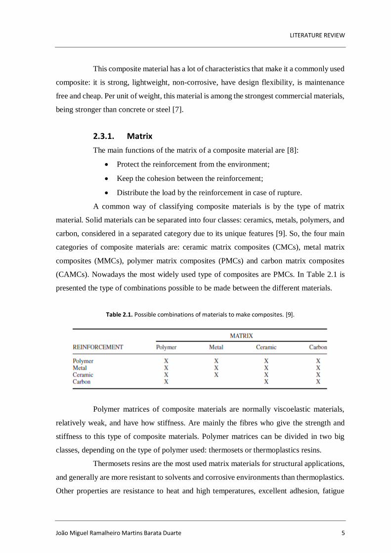
A common way of classifying composite materials is by the type of matrix
material. Solid materials can be separated into four classes: ceramics, metals, polymers, and
carbon, considered in a separated category due to its unique features [9]. So, the four main
categories of composite materials are: ceramic matrix composites (CMCs), metal matrix
composites (MMCs), polymer matrix composites (PMCs) and carbon matrix composites
(CAMCs). Nowadays the most widely used type of composites are PMCs. In Table 2.1 is
presented the type of combinations possible to be made between the different materials.
Table 2.1. Possible combinations of materials to make composites. [9].
Polymer matrices of composite materials are normally viscoelastic materials,
relatively weak, and have how stiffness. Are mainly the fibres who give the strength and
stiffness to this type of composite materials. Polymer matrices can be divided in two big
classes, depending on the type of polymer used: thermosets or thermoplastics resins.
Thermosets resins are the most used matrix materials for structural applications,
and generally are more resistant to solvents and corrosive environments than thermoplastics.
Other properties are resistance to heat and high temperatures, excellent adhesion, fatigue

Composite panels subjected to multi-impacts at different energy levels
6 2018
strength and excellent finishing. This resin passes through a curing process at elevated
temperatures, where resin cures permanently by irreversible cross linking [10], it makes the
material rigid and impossible to be reformed [9].
Thermoplastics resins don’t cure permanently, meaning that can be reformed and
reshaped. The resin remains solid at room temperature, but it can be heated and reshaped, by
a physical process, unlike the thermoset resins. These resins are more complex to process
when making a composite material than thermoset resins, and are also inadequate for
structural applications.
Some of the most common resins used are unsaturated polyesters, epoxies, and
vinyl esters; the least used resins are the polyurethanes and phenolics [10]. The most used
resin in glass fibre reinforced composites is unsaturated polyester, a thermoset resin [5].
Polyester resins can be classified has saturated or unsaturated resins. More than
75% of all polyester resins used in the world are from unsaturated polyester. This happens
because of their characteristics, it’s dimensional stable, has an affordable cost, it’s easy to
handle, process and fabricate. It can also be fire retardant and corrosion resistant. All of this
makes unsaturated polyester resins the best choice considering a balance between
performance and structural capacities [10]. In Table 2.2 are presented some typical
properties of these resins.
Table 2.2. Typical mechanical properties of Polyester Resins [10].
Tensile
Strength (MPa)
Modulus of
Elasticity
(GPa)
Density
(g/cm3)
Compressive
Strength
(MPa)
Flexural
Strength
(MPa)
Polyester
resins 40-85 1.3-4.5 1.1-1.4 140-410 205-690
2.3.2. Reinforcements
When talking about reinforcements, the discontinuous part, composite materials
can be divided in three main categories: particle-reinforced, fibre-reinforced and structural
(Figure 2.2).

LITERATURE REVIEW
João Miguel Ramalheiro Martins Barata Duarte 7
Figure 2.2. Scheme that shows the classification of reinforcements of composite materials [2].
The most common reinforcements used in composite materials are particles and
fibres (aligned continuous or discontinuous). The structural composites result from the
combination of composites with homogeneous materials.
In fibre-reinforced composites, the reinforcement (the fibres) are the main reason
to the great importance they achieved and to the improvement in their properties, when
compared to traditional materials they replace. The most important fibres for mechanical
engineering applications are the glass fibres, carbon fibres, several types of ceramics, and
high-modulus organics [9].
Glass fibres are made from glass, first it’s heathen until it molten, then it’s forced
to pass through superfine holes, creating thin glass filaments. These fibres are then woven
into large material pieces [11]. There are three main types of this fibres, E-glass, S-glass,
and C-glass. The first one is specially for electrical applications, the second one for high
strength parts, and the C-glass for high corrosion resistance purposes. The most widely used
reinforcement is the E-glass, which can be produced from silica sand, limestone and other
minerals, materials easy to obtain from raw materials like sand [5].
The original purpose of E-glass fibres was to provide isolation for electrical
wires, but later it was found that these fibres have an excellent fibre forming capabilities,
one of the many reasons for being widely used nowadays. Other reasons for this massive
utilization are these properties of E-glass fibres: low cost, high production rates, non-
flammable, relatively low density, impact resistance, and high strength [12]. Some
mechanical properties of typical E-glass fibres are presented in Table 2.3.
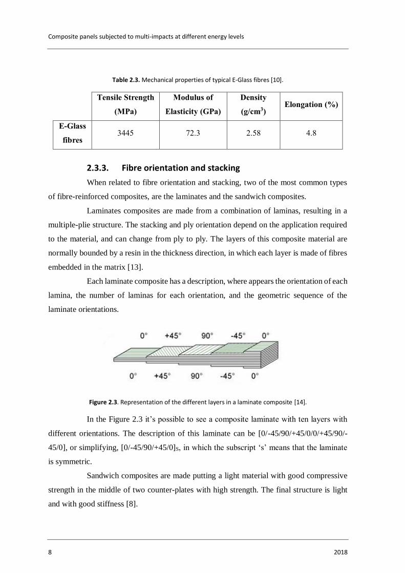
Composite panels subjected to multi-impacts at different energy levels
8 2018
Table 2.3. Mechanical properties of typical E-Glass fibres [10].
Tensile Strength
(MPa)
Modulus of
Elasticity (GPa)
Density
(g/cm3) Elongation (%)
E-Glass
fibres 3445 72.3 2.58 4.8
2.3.3. Fibre orientation and stacking
When related to fibre orientation and stacking, two of the most common types
of fibre-reinforced composites, are the laminates and the sandwich composites.
Laminates composites are made from a combination of laminas, resulting in a
multiple-plie structure. The stacking and ply orientation depend on the application required
to the material, and can change from ply to ply. The layers of this composite material are
normally bounded by a resin in the thickness direction, in which each layer is made of fibres
embedded in the matrix [13].
Each laminate composite has a description, where appears the orientation of each
lamina, the number of laminas for each orientation, and the geometric sequence of the
laminate orientations.
Figure 2.3. Representation of the different layers in a laminate composite [14].
In the Figure 2.3 it’s possible to see a composite laminate with ten layers with
different orientations. The description of this laminate can be [0/-45/90/+45/0/0/+45/90/-
45/0], or simplifying, [0/-45/90/+45/0]S, in which the subscript ‘s’ means that the laminate
is symmetric.
Sandwich composites are made putting a light material with good compressive
strength in the middle of two counter-plates with high strength. The final structure is light
and with good stiffness [8].

LITERATURE REVIEW
João Miguel Ramalheiro Martins Barata Duarte 9
2.4. Applications of composite materials
Composites materials can’t be considered the best type of material for every
application; besides their strengths they also have weaknesses, both presented in the next
paragraphs.
Strengths:
• Weight reduction, comparing to the materials they are replacing. The
main reason to choose a composite material is the specific
strength/stiffness;
• High strength, in result of the combination of properties from different
materials;
• Better durability, leading to less need of maintenance. A good example
of that is the excellent corrosion resistance in maritime applications;
• Design flexibility. Composites are made to suit a specific design for an
application, adding specific materials to help in that.
Weakness:
• Low toughness comparing to traditional materials;
• Service temperature is limited.
One of the oldest composites still in use is concrete, a mix of small stones or
gravel with cement and sand. This composite was improved by adding metal bars, which
lead to an increase of its tensile strength besides the good compressive strength of concrete
[6]. This improved concrete is called reinforced concrete.
Like it was said before, of all four classes of materials, polymer matrix
composites (PMC) are the dominant type of composite materials [9]. This class of composite
materials is present in almost all people daily lives, and some of the most common uses are:
• Aircraft industry;
• Marine industry;
• Sports equipment;
• Automotive components;
• Military equipment’s;
• Renewable energy industry;
• Constructions materials;

Composite panels subjected to multi-impacts at different energy levels
10 2018
• Space industry;
• Medical applications;
• Oil and gas industry.
Composites have been used in marine applications since several decades ago,
and the racing yachts are the marine structure that uses more composite materials. The main
objective is to achieve big velocities and have big resistance to impact, which can be obtain
with a low weight and maximum stiffness structure. The composites which are more used in
this application are the carbon fibre reinforced composites.
In the oil and gas industry, composite materials are being used in a lot of
applications, such as protection, pressure vessels, equipment and transportation pipes. The
piping systems used in oil transportation needs to resist to crude oil, high pressures and sea
water (for offshore applications). The properties that composite materials can offer, like high
service temperatures, good chemical resistance or good mechanical properties lead to their
application in oil transportation pipes [5].
One of the most known applications of composite materials is in the aircraft
industry, especially on airplanes fuselage. The airplane Boeing 787 is a good example of
this, having 50% of is airframe made with composite materials, like is presented in the
scheme of Figure 2.4. The change from the typical materials, like aluminium alloys, to
composites, allowed to reduce the weight of the aircraft in 20%. Almost half of the
composites used are carbon fibre reinforced plastic composites [15].
Figure 2.4. Scheme of the materials from which the airplane Boeing 787 is made [15].
LITERATURE REVIEW
João Miguel Ramalheiro Martins Barata Duarte 11
The research of composite materials continues, and nanomaterials and bio-based
polymers are some of the areas of greatest interest for researchers.
Every year, almost 2 million tons of unsaturated polyester resin components are
produced worldwide [16]. It can be used for sports equipment, car bodies, swimming pools,
surfboards, boat hulls, etc.
In aviation and aerospace, per example, this material can be used to produce
engine cowlings, luggage racks and antenna enclosures. It can also be used in medical
applications, like instrument enclosures or X-ray beds, due to X-ray transparency. This
material is also used in wind energy applications, almost every wind turbine blade is made
of a Glass-Fibre Reinforced Polymer.
2.5. Multi- Impact on Composite Materials
Due to their superior specific strength and stiffness, FRP composites have been
widely used in structural applications subjected to quasi static loading. However, in
aerospace, pipelines, or military applications, per example, these structures can be subjected
to high strain rates loadings coming from impact events. When this happens, the behaviour
of composite structures is normally poorer and more fragile than ductile materials such as
metals [17].
Impact events are usually classified using one of these three characteristics, by
velocity of impact, height of the drop weight or impact energy.
Although there is no official agreement in the classification of impacts, most of
the authors agree that it can be divided in two categories: low velocity impacts and high
velocity impacts. The transition between these two types is also not clear, and the opinions
of the authors diverge. According to [18] low velocity impacts happen for velocities lower
than 10 m/s. On the other hand, [19] stated that this type of impact occurs for impact speeds
smaller than 100m/s.
The low velocity impacts are considered one of the most dangerous loads on
composites materials, they can seriously affect the performance of these materials and are
also difficult to detect visually [20]. With these impacts different types of damage can occur:
matrix cracking, fibre-matrix deboning or fibre fracture. Nevertheless, the most common
Composite panels subjected to multi-impacts at different energy levels
12 2018
consequence of low impact events in composite materials is the delamination between layers
with different orientations [21].
Compressive and tensile strength are two of the most affected properties by these
events. Compressive strength is affected by the delamination phenomenon, being considered
a design limitation parameter. Normally, premature buckling happens has a consequence of
internal delaminations, which leads to a drop of the compressive strength. Tensile strength
also shows a decrease when an impact load exists, but is much less noticeable than
compressive one [21].
The energy of an impact load is normally absorbed by internal damage
mechanisms, result of an interaction of many damage types, preventing the appearance of
exterior signs of damage perceptible by visual inspection [21].
High velocity impacts are easier to detect, and a single impact can be enough to
break the structure. A bullet impact is a good example of a high velocity impact event. The
damage made by these are visible without any special technique, what makes easier their
detection and quick reparation [8].
To evaluate the behaviour of a material when subjected to impact events, an
experimental procedure is required, and to apply it a specified device is also needed. There
are two main typed of impact tests, pendulum and drop weight tests.
In pendulum tests a sample is used in the vertical position and a hammer is
released from a known high and it will crush into the specimen. The main objective of this
test is to calculate the energy lost in breaking the sample. Izod, Charpy (Figure 2.5) and
tensile impact are some of the most common pendulum tests. Simple impact tests, like these
ones, are useful, but don’t provide enough information about what’s happening to the sample
test during the impact. In the case of composites, per example, that can fail internally and
don’t show any damage externally, the information provided by these tests can be misleading
[22].

LITERATURE REVIEW
João Miguel Ramalheiro Martins Barata Duarte 13
Figure 2.5. Charpy test scheme [23].
In drop weight tests (Figure 2.6) a weight is drop in a vertical direction, guided
by a mechanism during the free fall. Both energy and velocity of impact can be changed for
the impact event. Some drop weight machines can provide information such as impact
energy, load, displacement or velocity versus time. Drop weight impact tests have some
advantages over other type of impact tests [22]:
• Can be used in moulded samples, moulded parts, etc;
• Doesn’t have a preferential direction of failure due to be a unidirectional
test. The failure appears in the weakest point of the test sample and
spread from there;
• The specimens can be considered failures even without breaking. The
failure can be defined by deformation, crack initiation, or complete
fracture, depending on the specifications needed.
Drop weight tests are considered the best simulation procedures of functional
impact events, and consequently closer to real life environments.

Composite panels subjected to multi-impacts at different energy levels
14 2018
Figure 2.6. Drop weight test machine scheme [24].
Nowadays almost all impact tests are instrumented, this means that load,
deformation and velocity during the entire period of impact event can be continuously
recorded as a function of time. This is achieved using electronic sensing instrumentation,
and can be applied to both test types explained above.
Multi-Impact tests are characterized by consecutive impacts in a sample of
material to be tested, and in each impact several properties can be measured and compared
between impacts, such as damage area, energy absorbed, maximum load, maximum
displacement, etc. These tests allow to predict the behaviour of a certain material or piece
when subjected to multi impacts.
The interest of the scientific community in the theme of multi-impact in
composite materials has been increasing in recent years. This can be understood in the graph
presented in Figure 2.7, where number of citations per year of articles about multi-impact in
composites is presented. The number of citations has been increasing in the last years, and a
big ride can be observed between 2012 and 2016.
Figure 2.7. Graphic showing the number of articles cited about multi-impact composites, between 1994 and
2017 [25].

LITERATURE REVIEW
João Miguel Ramalheiro Martins Barata Duarte 15
How it was shown, multi-impact fatigue test in composites is a theme studied by
a lot of researchers, but almost all of them are multi-impact events with the same level of
energy. This means that all the consecutive impacts applied in the sample of study has the
same energy.
On the other hand, multi-impact fatigue with different energy levels is something
that, to the author knowledge, was done just by [21]. This type of test is similar to the one
referred above, the only difference is that the energy applied changes between consecutive
impacts.
According to [21] the damage in the specimen increases with the value of the
higher impact event in each sequence. It was proved that a single impact of 3 J in the GFRP
composite in study was more detrimental when comparing to a cumulative damage made by
the multi-impact events with the sum of total energy of 3J. It was also proved that the energy
dissipated by the damage spread increases with the value of impact energy.
Table 2.4. Research done by the author related to multi-impact fatigue tests on composites.
Author (s) Title Ref.
Abir, M. R., Tay, T. E.,
Ridha, M., & Lee, H. P.
Modelling damage growth in composites subjected
to impact and compression after impact [26]
Ahmad, F., Hong, J. W.,
Choi, H. S., & Park, M. K.
Hygro effects on the low-velocity impact behavior
of unidirectional CFRP composite plates for aircraft
applications.
[27]
Amaro, A. M., Reis, P. N. B.,
& Neto, M. A.
Experimental study of temperature effects on
composite laminates subjected to multi-impacts. [20]
Amaro, A. M., Reis, P. N. B.,
de Moura, M. F. S. F., &
Neto, M. A.
Multi-Impact Response of Composite Laminates
with Open Holes. [28]
Amaro, A. M., Reis, P. N. B.,
de Moura, M. F. S. F., &
Neto, M. A.
Influence of multi-impacts on GFRP composites
laminates. [21]
Amaro, A. M., Reis, P. N. B.,
Santos, J. B., Santos, M. J., &
Neto, M. A.
Effect of the electric current on the impact fatigue
strength of CFRP composites. [29]
Ashcroft, I. A., Casas-
Rodriguez, J. P., &
Silberschmidt, V. V.
Mixed-mode crack growth in bonded composite
joints under standard and impact-fatigue loading. [30]
Azouaoui, K., Azari, Z., &
Pluvinage, G.
Evaluation of impact fatigue damage in glass/epoxy
composite laminate. [31]

Composite panels subjected to multi-impacts at different energy levels
16 2018
Azouaoui, K.,
Benmedakhene, S., Laksimi,
a., Azari, Z., & Pluvinage, G
Impact fatigue damage of glass/epoxy plates
predicted from three parameters model [32]
Azouaoui, K., Ouali, N.,
Ouroua, Y., Mesbah, A., &
Boukharouba, T.
Damage characterisation of glass/polyester
composite plates subjected to low-energy impact
fatigue.
[33]
Azouaoui, K., Rechak, S.,
Azari, Z., Benmedakhene, S.,
Laksimi, A., & Pluvinage, G.
Modelling of damage and failure of glass/epoxy
composite plates subject to impact fatigue. [34]
Barber, B. W., & Radford, D.
W.
Impact-fatigue behavior of composite tube/metal
end fitting bonded joints. [35]
Beheshty, M. H., & Harris, B.
A constant-life model of fatigue behaviour for
carbon-fibre composites: the effect of impact
damage.
[36]
Beheshty, M. H., Harris, B.,
& Adam, T.
An empirical fatigue-life model for high-
performance fibre composites with and without
impact damage.
[37]
Butler, R., Almond, D. P.,
Hunt, G. W., Hu, B., &
Gathercole, N.
Compressive fatigue limit of impact damaged
composite laminates. [38]
Coelho, S. R. M., Reis, P. N.
B., Ferreira, J. A. M., &
Pereira, A. M.
Effects of external patch configuration on repaired
composite laminates subjected to multi-impacts. [39]
de Vasconcellos, D. S.,
Sarasini, F., Touchard, F.,
Chocinski-Arnault, L., Pucci,
M., Santulli, C., …
Sorrentino, L.
Influence of low velocity impact on fatigue
behaviour of woven hemp fibre reinforced epoxy
composites.
[40]
Deka, L. J., Bartus, S. D., &
Vaidya, U. K.
Multi-site impact response of S2-glass/epoxy
composite laminates. [41]
Dhakal, H. N., Zhang, Z. Y.,
Bennett, N., & Reis, P. N. B.
Low-velocity impact response of non-woven hemp
fibre reinforced unsaturated polyester composites:
Influence of impactor geometry and impact velocity
[42]
Ding, Y. Q., Yan, Y., &
McIlhagger, R.
Effect of impact and fatigue loads on the strength of
plain weave carbon-epoxy composites. [43]
Dubary, N., Taconet, G.,
Bouvet, C., & Vieille, B.
Influence of temperature on the impact behavior and
damage tolerance of hybrid woven-ply thermoplastic
laminates for aeronautical applications.
[44]
Farrar, C., Hemez, F., Park,
G., Sohn, H., Robertson, A.,
& Williams, T.
Developing impact and fatigue damage prognosis
solutions for composites. [45]
Feng, D., & Aymerich, F. Finite element modelling of damage induced by
low-velocity impact on composite laminates. [46]
Feng, Y., He, Y., Tan, X.,
An, T., & Zheng, J.
Investigation on impact damage evolution under
fatigue load and shear-after-impact-fatigue (SAIF)
behaviors of stiffened composite panels.
[47]

LITERATURE REVIEW
João Miguel Ramalheiro Martins Barata Duarte 17
Freeman, B., Schwingler, E.,
Mahinfalah, M., & Kellogg,
K.
The effect of low-velocity impact on the fatigue life
of Sandwich composites. [48]
Garnier, C., Lorrain, B., &
Pastor, M.-L.
Impact damage evolution under fatigue loading by
InfraRed Thermography on composite structures. [49]
Garnier, C., Pastor, M.-L.,
Lorrain, B., & Pantalé, O. Fatigue behavior of impacted composite structures. [50]
Jang, B. P., Kowbel, W., &
Jang, B. Z.
Impact behavior and impact-fatigue testing of
polymer composites [51]
KATERELOS, D. G.,
PAIPETIS, A., &
KOSTOPOULOS, V.
A simple model for the prediction of the fatigue
delamination growth of impacted composite panels. [52]
Kim, S. J., & Hwang, I. H. Prediction of fatigue damage for composite laminate
using impact response. [53]
Koo, J.-M., Choi, J.-H., &
Seok, C.-S.
Evaluation for residual strength and fatigue
characteristics after impact in CFRP composites. [54]
Kostopoulos, V.,
Baltopoulos, A., Karapappas,
P., Vavouliotis, A., &
Paipetis, A.
Impact and after-impact properties of carbon fibre
reinforced composites enhanced with multi-wall
carbon nanotubes.
[55]
Lee, M., Cha, M. S., & Kim,
N. H.
Multi-scale modeling of composites subjected to
high speed impact. [56]
Lhymn, C. Impact fatigue of PPS/glass composite -
microscopy [57]
Lhymn, C. Impact fatigue of PPS/glass composites [58]
Margueres, P., Meraghni, F.,
& Benzeggagh, M. L.
Comparison of stiffness measurements and damage
investigation techniques for a fatigued and post-
impact fatigued GFRP composite obtained by RTM
process.
[59]
May, M., Nossek, M.,
Petrinic, N., Hiermaier, S., &
Thoma, K.
Adaptive multi-scale modeling of high velocity
impact on composite panels. [60]
Melin, L. G., & Schön, J.
Buckling behaviour and delamination growth in
impacted composite specimens under fatigue load:
an experimental study.
[61]
Mitrovic, M., Hahn, H. T.,
Carman, G. P., &
Shyprykevich, P.
Effect of loading parameters on the fatigue behavior
of impact damaged composite laminates. [62]
Montero, M. V., Barjasteh,
E., Baid, H. K., Godines, C.,
Abdi, F., & Nikbin, K.
Multi-Scale Impact and Compression-After-Impact
Modeling of Reinforced Benzoxazine/Epoxy
Composites using Micromechanics Approach.
[63]
Ouroua, Y., Azouaoui, K.,
Mesbah, A., Ouali, N., &
Boukharouba, T.
Some insights into the impact fatigue damage
behaviour in laminated composites. [64]
Ray, D., Sarkar, B. ., & Bose,
N. .
Impact fatigue behaviour of vinylester resin matrix
composites reinforced with alkali treated jute fibres. [65]
Composite panels subjected to multi-impacts at different energy levels
18 2018
Ren, Y., Qiu, L., Yuan, S., &
Su, Z.
A diagnostic imaging approach for online
characterization of multi-impact in aircraft
composite structures based on a scanning spatial-
wavenumber filter of guided wave.
[66]
Roy, R., Sarkar, B. K., &
Bose, N. R.
Impact fatigue of glass fibre–vinylester resin
composites. [67]
Roy, R., Sarkar, B. K., &
Bose, N. R.
Behaviour of E-glass fibre reinforced vinylester
resin composites under impact fatigue. [68]
Roy, R., Sarkar, B. K., Rana,
A. K., & Bose, N. R.
Impact fatigue behaviour of carbon fibre-reinforced
vinylester resin composites. [69]
Russo, P., Langella, A., Papa,
I., Simeoli, G., & Lopresto,
V.
Thermoplastic polyurethane/glass fabric composite
laminates: Low velocity impact behavior under
extreme temperature conditions.
[70]
Santos, R. A. M., Reis, P. N.
B., Santos, M. J., & Coelho,
C. A. C. P.
Effect of distance between impact point and hole
position on the impact fatigue strength of composite
laminates.
[71]
Santos, R. A. M., Reis, P. N.
B., Silva, F. G. A., & de
Moura, M. F. S. F.
Influence of inclined holes on the impact strength of
CFRP composites. [72]
Sarkar, B. K., & Ray, D.
Effect of the defect concentration on the impact
fatigue endurance of untreated and alkali treated
jute–vinylester composites under normal and liquid
nitrogen atmosphere.
[73]
Shi, Y., Pinna, C., & Soutis,
C.
Modelling impact damage in composite laminates:
A simulation of intra- and inter-laminar cracking. [74]
Sınmazçelik, T., Arıcı, A. A.,
& Günay, V.
Impact–fatigue behaviour of unidirectional carbon
fibre reinforced polyetherimide (PEI) composites. [75]
Sohn, M. ., Hu, X. ., Kim, J. .,
& Walker, L.
Impact damage characterisation of carbon
fibre/epoxy composites with multi-layer
reinforcement.
[76]
Soliman, E. M., Sheyka, M.
P., & Taha, M. R.
Low-velocity impact of thin woven carbon fabric
composites incorporating multi-walled carbon
nanotubes.
[17]
Sun, B., Hu, D., & Gu, B.
(2009).
Transverse impact damage and energy absorption of
3-D multi-structured knitted composite. [77]
Tai, N. ., Yip, M. ., & Lin, J. Effects of low-energy impact on the fatigue behavior
of carbon/epoxy composites. [78]
Tai, N. H., Ma, C. C. M., Lin,
J. M., & Wu, G. Y.
Effects of thickness on the fatigue-behavior of
quasi-isotropic carbon / epoxy composites before
and after low energy impacts
[79]
Taraghi, I., Fereidoon, A., &
Taheri-Behrooz, F.
Low-velocity impact response of woven
Kevlar/epoxy laminated composites reinforced with
multi-walled carbon nanotubes at ambient and low
temperatures.
[80]
Uyaner, M., Kara, M., &
Şahin, A.
Fatigue behavior of filament wound E-glass/epoxy
composite tubes damaged by low velocity impact. [81]

LITERATURE REVIEW
João Miguel Ramalheiro Martins Barata Duarte 19
Whitlow, T., & Sathish, S.
Characterization of multi-layered impact damage in
polymer matrix composites using lateral
thermography.
[82]
Yuanjian, T., & Isaac, D. H. Combined impact and fatigue of glass fiber
reinforced composites. [83]
Jefferson Andrew, J.,
Arumugam, V.,
Saravanakumar, K., Dhakal,
H. N., & Santulli, C.
Compression after impact strength of repaired GFRP
composite laminates under repeated impact loading. [84]
David-West, O. S., Nash, D.
H., & Banks, W. M.
An experimental study of damage accumulation in
balanced CFRP laminates due to repeated impact. [85]
Hosur, M. V., Karim, M. R.,
& Jeelani, S.
Experimental investigations on the response of
stitched/unstitched woven S2-glass/SC15 epoxy
composites under single and repeated low velocity
impact loading.
[86]
Richardson, M. O. W., &
Wisheart, M. J.
Review of low-velocity impact properties of
composite materials. [87]
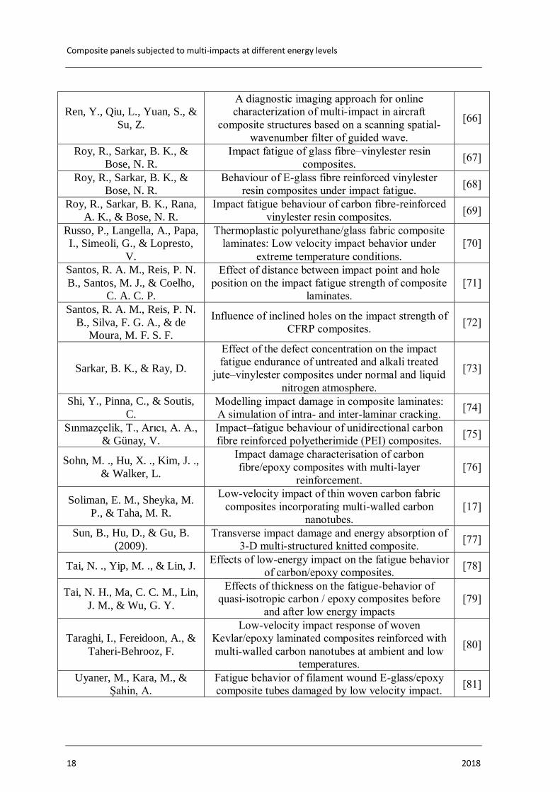
The research done to sustain this experimental study is presented in Table 2.4,
where all the 65 articles related to the issue in study are presented. From all these articles,
the most relevant ones were choosing to be presented throughout this Masters dissertation.

Composite panels subjected to multi-impacts at different energy levels
20 2018
MATERIALS AND EXPERIMENTAL PROCEDURE
João Miguel Ramalheiro Martins Barata Duarte 21
3. MATERIALS AND EXPERIMENTAL PROCEDURE
3.1. Introduction
This chapter intends to present all the materials, procedures and equipment used
in the experimental analysis. The main objective of this work, as explained before, is to study
the behaviour of composite materials subjected to multi impacts with different energy levels.
3.2. Test Samples (E-Glass/Polyester Laminate Composite)
The specimens are made of a glass fibre reinforced composite with E-Glass
fibres reinforcement in a matrix of polyester resin. The volume fraction of E-Glass fibre is
??? and it’s present in ?? layers. This material was prepared in ????? and processed in
agreement with manufacturer recommendations.
The process to obtain this laminate composite was ???, and the steps taken were:
???. The stacking sequence of this laminate is [90,0,90,0], and some of their mechanical
properties are presented in Table 3.1.
Table 3.1. Mechanical properties of E-Glass/Polyester Laminate Composite.
The test plates were cut from a bigger piece, resulting in samples with
dimensions of 100 x 100 x 2.4 mm3, which can be seen in Figure 3.1.
Composite panels subjected to multi-impacts at different energy levels
22 2018
Figure 3.1. Photography of a test piece used in the experimental tests.
3.3. Impact Tests Machine
All the impact tests were performed in an impact machine by weight drop,
property of DEM (FCTUC), which is placed in their facilities. The machine is CEAST 9340,
presented in Figure 3.2 a), developed by INSTRON®, which can deliver energy in the range
of 0.30 – 405 J [88]. This impact energy depends on the height and weight of the impactor.
The data acquisition system available, showed in Figure 3.2 b), allows to obtain time, load,
displacement, energy and velocity throughout the impact.

MATERIALS AND EXPERIMENTAL PROCEDURE
João Miguel Ramalheiro Martins Barata Duarte 23
a) b)
Figure 3.2. Equipment: a) Impact test machine CEAST 9340, and b) Data Acquisition System (DAS), both property of DEM (FCTUC).
During the tests the weight of the impactor was always the same, and what
changed was the height, allowing to obtain different impact energies, which is presented in
Table 3.2. The test samples were simply supported in a circular support of 70 mm of
diameter, where the impactor strokes at the centre of the sample obtained by centrally
supporting the 100 x 100 mm2 specimen. The mass of the impactor was 3.4 Kg and its
diameter 10 mm. Every test was done at room temperature (23oC).

Composite panels subjected to multi-impacts at different energy levels
24 2018
Table 3.2. Impact characteristics.
Energy [J] Height of impactor [mm] Impact Velocity [m/s]
3 0.090 1.330
4 0.119 1.530
5 0.149 1.710
6 0.180 1.880
8 0.240 2.170
10 0.301 2.430
3.4. Analysed Data
3.4.1. Number of Impacts
The first goal of this work is to find a valid model to relate the number of impacts
to failure with the impact energy. This is achieved using three test plates for each level of
energy (4J, 6J, 8J and 10J), and applying impacts to failure. The number of impacts is then
registered and all this data is used, with the help of a linear cumulative damage rule, to find
a valid model that relates impact energy with number of impacts.
In the study done in [33] and [69] the authors created a curve similar to S-N
classic fatigue curve, with the impact energy as a function of the failure impact number. In
[33], was conclude that this curve follows the classical fatigue behaviour, following a power
law.
One of the objectives of this dissertation is to understand if the model created
using a linear cumulative damage rule is reliable to demonstrate the behaviour of composites
when subjected to multi-impacts of different energy levels.
After obtaining the model based on the linear cumulative damage rule, multi-
impacts with different energy levels will be applied to the samples, and the results will be
compared to the theoretical prediction.
3.4.2. Area of Damage
After certain impact tests, some samples were inspected to evaluate the shape
and size of the visible damaged zone. The glass-laminated plates are translucent, so it is
possible to observe, measure and photograph the projection of the damaged area in counter-
light using a powerful light source.

MATERIALS AND EXPERIMENTAL PROCEDURE
João Miguel Ramalheiro Martins Barata Duarte 25
The specimens were framed in a window so that all the light could fall upon
them. Then they were photographed and the visible damaged zone measured using a calliper,
presented in Figure 3.3.
Figure 3.3. Calliper measuring visible damaged zone.
The area of damaged zone was approximated to a parallelepiped, because it’s
easier to measure with the calliper. The error obtain with this approximation in each
measurement will be similar, so the comparation between the different value of areas will be
reliable. When comparing this parameter along the impacts, the objective is to compare the
evolution of it and not its exact size.
The damaged area increases with number of impacts, but after certain number of
impacts it does no increase significantly [86]. According to [33], the damaged area grows
considerably for a high number of impacts when the energy of impact is low (3.5J and 4J),
and it grows rapidly for a low number of impacts when the energy of impact is high (≥ 5J).
It was observed that the area of damage as function of impact number presents a linear
evolution when in presence of cyclic impact events, and also that the higher the impact
energy, the bigger is the slope of the straight line which relates them.

Composite panels subjected to multi-impacts at different energy levels
26 2018

RESULTS AND DISCUSSION
João Miguel Ramalheiro Martins Barata Duarte 27
4. RESULTS AND DISCUSSION
Figure 4.1 shows the profile of typical curves obtained for different impact
energies.
a)
b)
Figure 4.1. Typical load a) and energy b) versus time curves for different values of impact energy, for the 1st impact.
0
1000
2000
3000
4000
5000
6000
0 1 2 3 4 5 6 7
Load
[N
]
Time [ms]
4 J 6 J
8 J 10 J
0
2
4
6
8
10
0 1 2 3 4 5 6 7 8 9
Ener
gy [J
]
Time [ms]
4 J 6 J
8 J 10 J
Composite panels subjected to multi-impacts at different energy levels
28 2018
Figure 4.1 a) presents typical load versus time curves for the first impact when
four different impact energies are applied. The behaviour of this curves is typical and agrees
with those reported in literature [21], [55], [76], [86]. It’s perceptible that the load increases
up to a maximum value followed by a drop corresponding to the impactor rebound. Both
maximum load and slop of the curve increase with the increasing of the impact energy.
Figure 4.1 b) represents a typical energy versus time curves for different values
of impact energy. After the peak of maximum energy exists a plateau, and its beginning
indicates the contact loss between the impactor and the specimen [20], [21], [28]. The
difference between the maximum energy value and the energy defined by the plateau is the
elastic energy, energy retained by the impactor and used to rebound after impact [55]. This
property will be presented as a percentage of the impact energy applied.
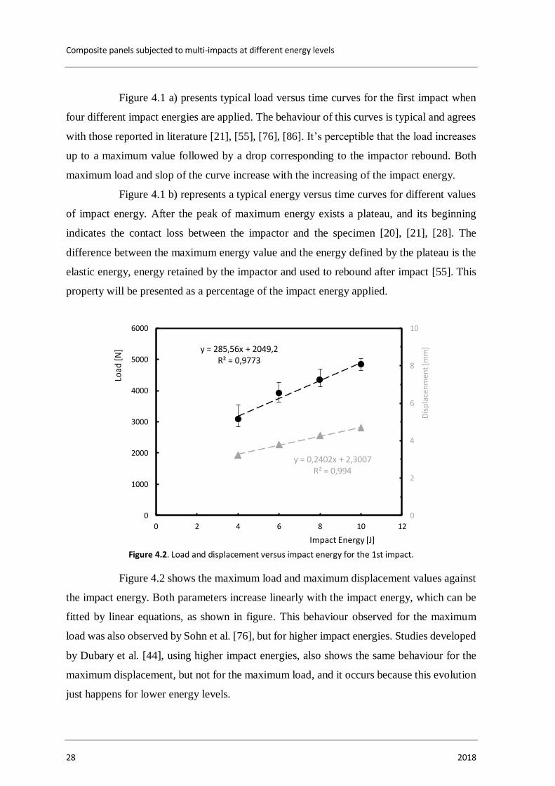
Figure 4.2. Load and displacement versus impact energy for the 1st impact.
Figure 4.2 shows the maximum load and maximum displacement values against
the impact energy. Both parameters increase linearly with the impact energy, which can be
fitted by linear equations, as shown in figure. This behaviour observed for the maximum
load was also observed by Sohn et al. [76], but for higher impact energies. Studies developed
by Dubary et al. [44], using higher impact energies, also shows the same behaviour for the
maximum displacement, but not for the maximum load, and it occurs because this evolution
just happens for lower energy levels.
y = 285,56x + 2049,2R² = 0,9773
y = 0,2402x + 2,3007R² = 0,994
0
2
4
6
8
10
0
1000
2000
3000
4000
5000
6000
0 2 4 6 8 10 12
Dis
pla
cen
men
t [m
m]
Load
[N
]
Impact Energy [J]

RESULTS AND DISCUSSION
João Miguel Ramalheiro Martins Barata Duarte 29
Error bars presented in Figure 4.2 represent the maximum and minimum values
obtained from the three tests performed for each condition. It is possible to conclude that the
dispersion observed is very low, especially in terms of displacement, where the bars are not
visible due to their reduced dispersion. The standard deviation obtained range from 0.9% for
the maximum displacement observed for 6 J, and 10.4 % that is related to the maximum load
obtained for 4 J.
Figure 4.3. Elastic energy and impact bending stiffness (IBS) versus impact energy for the 1st impact.
Elastic energy, the energy that is dissipated by the plate test at the impact, shows
a linear evolution with the impact energy (Figure 4.3), presenting a decrease with the
increasing values of impact energy due to higher damages introduced [39], [84], [90]. For
an impact energy of 4 J, the elastic energy is about 73.5%, while for 10 J it is 53.5% of the
impact energy value. This behaviour is typical of composite materials, like it is shown by
the literature [20], [21], [39], [55]. The standard deviation of these results present values
between 1.1% and 7.1% for 10 J and 6 J impact, respectively.
Impact bending stiffness (IBS) is known as an important property for evaluation
of damage resistance of a composite [20], [39], [85], [90]. The slope of the ascending section
of the load-displacement plot is the bending stiffness, and it varies with the composite
configuration [85]. According to Figure 4.3 this property seems to change with the impact
energy, increasing directly with its value. For 4 J the IBS is 956.61 N/mm and it increases
y = -3,491x + 88,854R² = 0,9701
y = 32,054x + 841,4R² = 0,9714
800
1000
1200
1400
1600
1800
2000
0
10
20
30
40
50
60
70
80
90
100
0 2 4 6 8 10 12
Imp
act
Ben
din
g St
iffn
ess
[N/m
m]
Elas
tic
Ener
gy [%
]
Impact Energy [J]

Composite panels subjected to multi-impacts at different energy levels
30 2018
to 1150.67 N/mm for 10 J. The values of standard deviation range from 38.6% for 4 J to
50.7% for 10 J.
Both elastic energy and impact bending stiffness can be used to understand the
damage evolution of a composite subjected to impact events. For the first impact, like it was
referred before, these properties vary in an opposite tendency with the impact energy.
Finally, the contact time of impact was also recorded, and the values obtained
are between 6.5 ms for 4 J and 5.9 ms for 10 J.
a) b)
c) d)
Figure 4.4. Typical damage observed in the test samples after the 1st impact for an impact energy of: a) 4 J; b) 6 J; c) 8 J; d) 10 J
Figure 4.4 presents the area of the damage observed in the first impact for
different energies. It is possible to observe an increasing of the damage for higher impact
energies, what is in good agreement with literature [33], [44], [55], [86]. The damaged area
for the first impact of 4 J is around 498.5 mm2, and about 1252.0 mm2 for 10 J.
10 mm 10 mm
10 mm 10 mm

RESULTS AND DISCUSSION
João Miguel Ramalheiro Martins Barata Duarte 31
In order to obtain the impact fatigue life, the samples were subjected to multi-
impacts with the same energy level. The final failure is considered when full perforation
(when the impactor completely moves through the sample) occurs.
Figure 4.5. Impact energy versus number of impacts to failure.
Figure 4.5 shows the impact energy versus number of impacts to failure, with
both scales logarithmized. This representation is based on the typical fatigue S-N curves,
where the stress is substituted by the impact energy. The number of impacts to failure varies
inversely with the impact energy, and this behaviour is according with the literature [33],
[39], [44], [64], [68].
The impact energy versus number of impacts can be express by the equation
(4.1), with R=0.9703:
𝐸 = 12.138 × 𝑁𝑓−0.223 (4.1)
where, 𝐸 is the impact energy and 𝑁𝑓 the number of impacts to failure.
Similar to the analysis done for the first impact, the same parameters were
analysed in a dimensionless format (N/Nf), where the N is the number of impacts at any
given instant of the test and Nf is the number of impacts to failure. The last impact isn’t
presented because full perforation occurred.
1
10
100
1 10 100 1000
Ener
gy [J
]
Nr. of Impacts
(3 ×)
(3 ×)(2 ×)

Composite panels subjected to multi-impacts at different energy levels
32 2018
a)
b)
Figure 4.6. Maximum impact load (a) and maximum displacement (b) versus N/Nf.
Figure 4.6 represents the effect of the multi-impacts on the maximum load and
maximum displacement. It’s possible to observe, for all impact energies, that the maximum
0
1000
2000
3000
4000
5000
6000
0 0,2 0,4 0,6 0,8 1
Load
[N
]
N/Nf
4 J6 J8 J10 J
0
1
2
3
4
5
6
7
8
0 0,2 0,4 0,6 0,8 1
Dis
pla
cem
ent
[mm
]
N/Nf
4 J6 J8 J10 J

RESULTS AND DISCUSSION
João Miguel Ramalheiro Martins Barata Duarte 33
load decreases with the number of impacts, while the maximum displacement increases,
which is in good agreement with open literature [8], [20], [28], [34], [39]. Curves for 4 J and
6 J can be fitted by polynomial of order three, presenting three stages, as consequence of
damage accumulation [20], [34], [39]. Curves for 8 J and 10 J can be fitted by a polynomial
of order two, showing fast evolution, due to the severity of the damage.
a)
b)
Figure 4.7. Elastic energy (a) and impact bending stiffness (b) versus N/Nf.
0
10
20
30
40
50
60
70
80
90
100
0 0,2 0,4 0,6 0,8 1
Elas
tic
Ener
gy [%
]
N/Nf
4 J
6 J
8 J
0
200
400
600
800
1000
1200
1400
1600
0 0,2 0,4 0,6 0,8 1
Imp
act
Ben
din
g St
iffn
ess
[N/m
m]
N/Nf
10 J
8 J
6 J

Composite panels subjected to multi-impacts at different energy levels
34 2018
Figure 4.7 presents the evolution of the damage in terms of elastic energy and
impact bending stiffness. According to Figure 4.7 a), the impact energies of 8 J and 10 J can
be fitted by a polynomial of order two, which means that, after starting the damage, its
progress is very fast. On the other hand, for energies of 4 J and 6 J the data are fitted by
polynomial curves of order three. In this case, three stages can be seen in those curves. In
the beginning, the elastic energy decreases quickly as consequence of the damage
introduced, and matrix cracking is the predominant damage mode. In the second stage, the
curve shows a linear evolution, and it’s when the fast delamination propagation takes place
until saturation. The elastic energy drops suddenly in the third stage, because the fibre
breakage decreases the local rigidity at the point of impact.[91]. For the 4 J, the first stage
represents about 25%, the second one 35%, and the last one 40% of the total lifetime, while
these values are around 20%, 25% and 55%, respectively for 6 J.
Figure 4.7 b) shows the IBS evolution with number of impacts to failure. Similar
to Figure 4.7 a), for 8 J and 10 J, the data are fitted by a polynomial of order two, while for
4 J and 6 J they are fitted by a polynomial of order three. One more time, for the first case
(energies of 8 J and 10 J), the damage progress is very abrupt, while for the other energies
three stages of damage can be identified, which is in agreement with literature [20], [31],
[32], [39]. The progression of damage in these three stages is the same that was described
for the elastic energy. For the 4 J the first stage represents about 25% of the total life, the
second one 35%, and the third one the remaining 40%. In terms of 6 J, these values are about
20%, 30% and 50%, respectively.
The evolution of elastic energy and impact bending stiffness relate to each other
and with damage evolution. The percentage of each stage for the curves of 4 J and 6 J is
similar for both parameters. This occurs because of the relation between both: with the
decreasing values of elastic energy, the energy absorbed increases allowed by the damage
mechanisms of the composite, which takes to a decrease of the plate stiffness (IBS).
From the previous analysis, it is possible to observe that the damage evolution
is very similar for all impact energies studied. However, for higher energies, the damage
progress occurs faster.

RESULTS AND DISCUSSION
João Miguel Ramalheiro Martins Barata Duarte 35
a) b)
c) d)
Figure 4.8. Typical damage observed for the impact energy of 4 J after: a) 1st impact; b) 45th impact; c) 105th impact; d) penultimate impact.
Figure 4.8 presents, for example, the damage’s evolution for 4 J. The average
area for the 1st impact is 498.5 mm2, for the 45th impact is around 1819.6 mm2, for the 105th
is 2035.5 mm2, and for the penultimate one about 2117.4 mm2. The last three impacts
referred previously represent an increase, relatively to the 1st impact, around 265.0%,
308.3% and 324.8%, respectively. The standard deviation values are around 4.3%, 4.0%,
2.5% and 2.9%, respectively.
Finally, the development of reliable methods for predicting impact fatigue lives
is important, although this task is complex in composite laminates as a consequence of the
multiple failure modes. For this purpose, experimental tests composed of two blocks,
changing from a low energy level to a higher energy level (L–H sequence) or vice versa (H–
L sequence), were performed. The first block was defined as one third of the impact fatigue
life, obtained with constant energy, and the second one was applied up to failure.
On the other hand, based on a linear cumulative damage rule, the impact fatigue
life is estimated assuming that the damage caused by each block should not be affected by
10 mm
10 mm
10 mm
10 mm

Composite panels subjected to multi-impacts at different energy levels
36 2018
the impact load history. According to this rule, the failure during an impact test with variable
energies must occur when:
∑𝑛𝑖𝑁𝑖
= 1
𝑘
𝑖=0
(4.2)
where 𝑛𝑖 is the number of cycles applied at an energy level block corresponding to a lifetime
of 𝑁𝑖. Therefore, the damage summation (𝐷) during a variable frequency fatigue test should
tend to 1.
Figure 4.9. Experimental number of impacts versus theoretical number of impacts.
In this context, Figure 4.9 presents the comparison between estimated and
experimental results. It is possible to observe that the average ratio between predictions and
experimental lives are not close to unit. Therefore, it can be concluded that the linear
cumulative damage rule is not applicable to predict the fatigue life in multi-impact tests with
variable energy levels for GFRP.
0
20
40
60
80
100
120
140
160
0 20 40 60 80 100 120 140 160
Exp
erim
enta
l nu
mb
er o
f im
pac
ts
Theoretical number of impacts
4 J + 5 J
5 J + 4 J

CONCLUSIONS AND SUGGESTIONS FOR FUTURE WORK
João Miguel Ramalheiro Martins Barata Duarte 37
5. CONCLUSIONS AND SUGGESTIONS FOR FUTURE WORK
5.1. Introduction
After finishing the tests and analysing the results according to the objectives
imposed initially, it’s now possible to reach to some important conclusions.
It is also possible to think in future work that can be done to support the
conclusions and to study multi-impact events on composites in different ways.
5.2. Conclusions
According to the main goal proposed for the present study, the most significant
conclusions are:
1. Maximum load and maximum displacement increase with the increasing
of the impact energy;
2. For the first impact, elastic energy decreases with the increasing of
impact energy, and the impact bending stiffness shows the opposite
tendency;
3. The impact energy versus number of impacts to failure can be fitted by a
power function, like the S-N curves for fatigue;
4. Maximum load increase with the number of impacts and maximum
displacement shows the opposite tendency;
5. The evolution of elastic energy and impact bending stiffness with number
of impacts show curves with three stages for low energy levels;
6. Both IBS and elastic energy describe with enough precision the evolution
of the damage;
7. The linear cumulative damage rule is not applicable to predict the fatigue
life in multi-impact tests with variable energy levels for GFRP.
Composite panels subjected to multi-impacts at different energy levels
38 2018
5.3. Suggestions for Future Work
From the conclusions obtained and all constrains occurred along this study, it is
possible to suggest some ideas for future works:
1. To perform multi-impact tests at lower energies, in order to have a more
realistic curve of impact energy versus number of impacts to failure;
2. Develop tests with sequences composed by different energy blocks;
3. Develop a similar study for other composite materials;
4. Study the influence of different environmental conditions on the impact
fatigue life.

BIBLIOGRAPHY
João Miguel Ramalheiro Martins Barata Duarte 39
BIBLIOGRAPHY
[1] W. F. Smith, Principles of Materials Science and Engineering, Third Ed. McGraw-
Hill, Inc., 1998.
[2] W. D. Callister, Fundamentals of Materials Science and Engineering, Fifth Ed. John
Wiley & Sons, Inc., 2001.
[3] ThoughtCo., “History of Composites, The Evolution of Lightweight Composite
Materials.” [Online]. Available: https://www.thoughtco.com/history-of-composites-
820404. [Accessed: 20-May-2018].
[4] M. F. Ashby, Materials Selection in Mechanical Design, Second Ed. Oxford:
Butterworth-Heinemann, 1999.
[5] CompositesUK, “Introduction to Composite Materials.” [Online]. Available:
https://compositesuk.co.uk/composite-materials/introduction. [Accessed: 20-May-
2018].
[6] Royal Society of Chemistry, “Composites Materials.” [Online]. Available:
http://www.rsc.org/Education/Teachers/Resources/Inspirational/resources/4.3.1.pdf.
[Accessed: 21-May-2018].
[7] B-HYGIENIC, “FRP material – Fibreglass Reinforced Polyester.” [Online].
Available: https://www.b-hygienic.com/frp-fibreglass-reinforced-polyester/.
[Accessed: 28-May-2018].
[8] J. J. Costa, “O efeito abrasivo da resistência ao impacto de materiais compósitos,”
University of Coimbra, 2014.
[9] M. Kutz, Mechanical Engineers’ Handbook, Fourth Ed. John Wiley & Sons, Inc.,
2015.
[10] S. Bagherpour, “Fibre Reinforced Polyester Composites (Composition Perfect),”
Polyester, pp. 135–166, 2012.
[11] ThoughtCo., “What is Fiberglass?” [Online]. Available:
https://www.thoughtco.com/what-is-fiberglass-or-glass-fiber-820469. [Accessed:
31-May-2018].
Composite panels subjected to multi-impacts at different energy levels
40 2018
[12] AZO Materials, “E-Glass Fibre.” [Online]. Available:
https://www.azom.com/article.aspx?ArticleID=764. [Accessed: 04-Jun-2018].
[13] R. Velmurugan, “Composite Materials,” Lecture 29 (Module IV – Macro-mechanics
of laminate). [Online]. Available:
http://nptel.ac.in/courses/101106038/mod04lec01.pdf. [Accessed: 22-May-2018].
[14] QUARTUS Engineering, “Composites 101.” [Online]. Available:
https://www.quartus.com/resources/composites-101/. [Accessed: 22-May-2018].
[15] Boeing, “Boeing 787, From the ground up.” [Online]. Available:
http://www.boeing.com/commercial/aeromagazine/articles/qtr_4_06/article_04_2.ht
ml. [Accessed: 27-May-2018].
[16] ThoughtCo., “Uses of Fibergalass.” [Online]. Available:
https://www.thoughtco.com/uses-of-fiberglass-820412. [Accessed: 04-Jun-2018].
[17] E. M. Soliman, M. P. Sheyka, and M. R. Taha, “Low-velocity impact of thin woven
carbon fabric composites incorporating multi-walled carbon nanotubes,” Int. J.
Impact Eng., vol. 47, pp. 39–47, Sep. 2012.
[18] C. D. D., Carbon Fiber Composites. Boston: Butterworth - Heinemann, 1994.
[19] A. S., Impact on Composites Structures. Cambridge: University Press, 1998.
[20] A. M. Amaro, P. N. B. Reis, and M. A. Neto, “Experimental study of temperature
effects on composite laminates subjected to multi-impacts,” Compos. Part B Eng.,
vol. 98, pp. 23–29, Aug. 2016.
[21] A. M. Amaro, P. N. B. Reis, M. F. S. F. de Moura, and M. A. Neto, “Influence of
multi-impacts on GFRP composites laminates,” Compos. Part B Eng., vol. 52, pp.
93–99, Sep. 2013.
[22] INSTRON®, “Impact Test Types.” [Online]. Available: http://www.instron.us/en-
us/our-company/library/test-types/impact-testing/test-types. [Accessed: 25-Jun-
2018].
[23] School of Materials Science and Engineering, “1: Charpy Impact Test.” [Online].
Available: http://www.materials.unsw.edu.au/tutorials/online-tutorials/1-charpy-
impact-test. [Accessed: 26-Jun-2018].
[24] UNIVER, “Test Solutions.” [Online]. Available: http://www.univer-test.com/en/sol-
detail.asp?id=177. [Accessed: 26-Jun-2018].

BIBLIOGRAPHY
João Miguel Ramalheiro Martins Barata Duarte 41
[25] Web of Science, “Web of Science.” [Online]. Available:
https://apps.webofknowledge.com/CitationReport.do?product=WOS&search_mode
=CitationReport&SID=E5KfSAoxfHJEbTniIZF&page=1&cr_pqid=1&viewType=s
ummary&colName=WOS. [Accessed: 26-Jun-2018].
[26] M. R. Abir, T. E. Tay, M. Ridha, and H. P. Lee, “Modelling damage growth in
composites subjected to impact and compression after impact,” Compos. Struct., vol.
168, pp. 13–25, 2017.
[27] F. Ahmad, J. W. Hong, H. S. Choi, and M. K. Park, “Hygro effects on the low-velocity
impact behavior of unidirectional CFRP composite plates for aircraft applications,”
Compos. Struct., vol. 135, pp. 276–285, 2016.
[28] A. M. Amaro, P. N. B. Reis, M. F. S. F. de Moura, and M. A. Neto, “Multi-Impact
Response of Composite Laminates with Open Holes,” Wiley Online Libr., 2016.
[29] A. M. Amaro, P. N. B. Reis, J. B. Santos, M. J. Santos, and M. A. Neto, “Effect of
the electric current on the impact fatigue strength of CFRP composites,” Compos.
Struct., vol. 182, pp. 191–198, Dec. 2017.
[30] I. A. Ashcroft, J. P. Casas-Rodriguez, and V. V. Silberschmidt, “Mixed-mode crack
growth in bonded composite joints under standard and impact-fatigue loading,” J.
Mater. Sci., vol. 43, no. 20, pp. 6704–6713, 2008.
[31] K. Azouaoui, Z. Azari, and G. Pluvinage, “Evaluation of impact fatigue damage in
glass/epoxy composite laminate,” Int. J. Fatigue, vol. 32, no. 2, pp. 443–452, Feb.
2010.
[32] K. Azouaoui, S. Benmedakhene, a. Laksimi, Z. Azari, and G. Pluvinage, “Impact
fatigue damage of glass/epoxy plates predicted from three parameters model,” 12th
Int. Conf. Fract. 2009, ICF-12, vol. 5, pp. 3795–3804, 2009.
[33] K. Azouaoui, N. Ouali, Y. Ouroua, A. Mesbah, and T. Boukharouba, “Damage
characterisation of glass/polyester composite plates subjected to low-energy impact
fatigue,” J. Sound Vib., vol. 308, no. 3–5, pp. 504–513, Dec. 2007.
[34] K. Azouaoui, S. Rechak, Z. Azari, S. Benmedakhene, A. Laksimi, and G. Pluvinage,
“Modelling of damage and failure of glass/epoxy composite plates subject to impact
fatigue,” Int. J. Fatigue, vol. 23, no. 10, pp. 877–885, Nov. 2001.
[35] B. W. Barber and D. W. Radford, “Impact-fatigue behavior of composite tube/metal
end fitting bonded joints,” Compos. Eng., vol. 5, no. 8, pp. 995–1009, Jan. 1995.

Composite panels subjected to multi-impacts at different energy levels
42 2018
[36] M. H. Beheshty and B. Harris, “A constant-life model of fatigue behaviour for carbon-
fibre composites: the effect of impact damage,” Compos. Sci. Technol., vol. 58, no. 1,
pp. 9–18, Jan. 1998.
[37] M. H. Beheshty, B. Harris, and T. Adam, “An empirical fatigue-life model for high-
performance fibre composites with and without impact damage,” Compos. Part A
Appl. Sci. Manuf., vol. 30, no. 8, pp. 971–987, Aug. 1999.
[38] R. Butler, D. P. Almond, G. W. Hunt, B. Hu, and N. Gathercole, “Compressive fatigue
limit of impact damaged composite laminates,” Compos. Part A Appl. Sci. Manuf.,
vol. 38, no. 4, pp. 1211–1215, Apr. 2007.
[39] S. R. M. Coelho, P. N. B. Reis, J. A. M. Ferreira, and A. M. Pereira, “Effects of
external patch configuration on repaired composite laminates subjected to multi-
impacts,” Compos. Struct., vol. 168, pp. 259–265, May 2017.
[40] D. S. de Vasconcellos et al., “Influence of low velocity impact on fatigue behaviour
of woven hemp fibre reinforced epoxy composites,” Compos. Part B Eng., vol. 66,
pp. 46–57, Nov. 2014.
[41] L. J. Deka, S. D. Bartus, and U. K. Vaidya, “Multi-site impact response of S2-
glass/epoxy composite laminates,” Compos. Sci. Technol., vol. 69, no. 6, pp. 725–
735, May 2009.
[42] H. N. Dhakal, Z. Y. Zhang, N. Bennett, and P. N. B. Reis, “Low-velocity impact
response of non-woven hemp fibre reinforced unsaturated polyester composites:
Influence of impactor geometry and impact velocity,” Compos. Struct., vol. 94, no. 9,
pp. 2756–2763, 2012.
[43] Y. Q. Ding, Y. Yan, and R. McIlhagger, “Effect of impact and fatigue loads on the
strength of plain weave carbon-epoxy composites,” J. Mater. Process. Technol., vol.
55, no. 2, pp. 58–62, Nov. 1995.
[44] N. Dubary, G. Taconet, C. Bouvet, and B. Vieille, “Influence of temperature on the
impact behavior and damage tolerance of hybrid woven-ply thermoplastic laminates
for aeronautical applications,” Compos. Struct., vol. 168, pp. 663–674, 2017.
[45] C. Farrar, F. Hemez, G. Park, H. Sohn, A. Robertson, and T. Williams, “Developing
impact and fatigue damage prognosis solutions for composites,” JOM, vol. 56, no. 3,
pp. 40–42, Mar. 2004.

BIBLIOGRAPHY
João Miguel Ramalheiro Martins Barata Duarte 43
[46] D. Feng and F. Aymerich, “Finite element modelling of damage induced by low-
velocity impact on composite laminates,” Compos. Struct., vol. 108, pp. 161–171,
2014.
[47] Y. Feng, Y. He, X. Tan, T. An, and J. Zheng, “Investigation on impact damage
evolution under fatigue load and shear-after-impact-fatigue (SAIF) behaviors of
stiffened composite panels,” Int. J. Fatigue, vol. 100, pp. 308–321, Jul. 2017.
[48] B. Freeman, E. Schwingler, M. Mahinfalah, and K. Kellogg, “The effect of low-
velocity impact on the fatigue life of Sandwich composites,” Compos. Struct., vol. 70,
no. 3, pp. 374–381, Sep. 2005.
[49] C. Garnier, B. Lorrain, and M.-L. Pastor, “Impact damage evolution under fatigue
loading by InfraRed Thermography on composite structures.”
[50] C. Garnier, M.-L. Pastor, B. Lorrain, and O. Pantalé, “Fatigue behavior of impacted
composite structures,” Compos. Struct., vol. 100, pp. 443–450, Jun. 2013.
[51] B. P. Jang, W. Kowbel, and B. Z. Jang, “Impact behavior and impact-fatigue testing
of polymer composites,” Compos. Sci. Technol., vol. 44, no. 2, pp. 107–118, Jan.
1992.
[52] D. G. KATERELOS, A. PAIPETIS, and V. KOSTOPOULOS, “A simple model for
the prediction of the fatigue delamination growth of impacted composite panels,”
Fatigue <html_ent glyph="@amp;" ascii="&"/> Fract. Eng. Mater. Struct.,
vol. 27, no. 10, pp. 911–922, Oct. 2004.
[53] S. J. Kim and I. H. Hwang, “Prediction of fatigue damage for composite laminate
using impact response,” Int. J. Fatigue, vol. 28, no. 10, pp. 1334–1339, Oct. 2006.
[54] J.-M. Koo, J.-H. Choi, and C.-S. Seok, “Evaluation for residual strength and fatigue
characteristics after impact in CFRP composites,” Compos. Struct., vol. 105, pp. 58–
65, Nov. 2013.
[55] V. Kostopoulos, A. Baltopoulos, P. Karapappas, A. Vavouliotis, and A. Paipetis,
“Impact and after-impact properties of carbon fibre reinforced composites enhanced
with multi-wall carbon nanotubes,” Compos. Sci. Technol., vol. 70, no. 4, pp. 553–
563, Apr. 2010.
[56] M. Lee, M. S. Cha, and N. H. Kim, “Multi-scale modeling of composites subjected to
high speed impact,” in AIP Conference Proceedings, 2017, vol. 1793, no. 1, p.
100028.

Composite panels subjected to multi-impacts at different energy levels
44 2018
[57] C. Lhymn, “Impact fatigue of PPS/glass composite - microscopy,” J. Mater. Sci. Lett.,
vol. 4, no. 12, pp. 1429–1433, Dec. 1985.
[58] C. Lhymn, “Impact fatigue of PPS/glass composites,” J. Mater. Sci. Lett., vol. 4, no.
10, pp. 1221–1224, Oct. 1985.
[59] P. Margueres, F. Meraghni, and M. L. Benzeggagh, “Comparison of stiffness
measurements and damage investigation techniques for a fatigued and post-impact
fatigued GFRP composite obtained by RTM process,” Compos. Part A Appl. Sci.
Manuf., vol. 31, no. 2, pp. 151–163, Feb. 2000.
[60] M. May, M. Nossek, N. Petrinic, S. Hiermaier, and K. Thoma, “Adaptive multi-scale
modeling of high velocity impact on composite panels,” Compos. Part A Appl. Sci.
Manuf., vol. 58, pp. 56–64, Mar. 2014.
[61] L. G. Melin and J. Schön, “Buckling behaviour and delamination growth in impacted
composite specimens under fatigue load: an experimental study,” Compos. Sci.
Technol., vol. 61, no. 13, pp. 1841–1852, Oct. 2001.
[62] M. Mitrovic, H. T. Hahn, G. P. Carman, and P. Shyprykevich, “Effect of loading
parameters on the fatigue behavior of impact damaged composite laminates,”
Compos. Sci. Technol., vol. 59, no. 14, pp. 2059–2078, Nov. 1999.
[63] M. V. Montero, E. Barjasteh, H. K. Baid, C. Godines, F. Abdi, and K. Nikbin, “Multi-
Scale Impact and Compression-After-Impact Modeling of Reinforced
Benzoxazine/Epoxy Composites using Micromechanics Approach,” J. Multiscale
Model., vol. 08, no. 01, p. 1750002, Mar. 2017.
[64] Y. Ouroua, K. Azouaoui, A. Mesbah, N. Ouali, and T. Boukharouba, “Some insights
into the impact fatigue damage behaviour in laminated composites.”
[65] D. Ray, B. . Sarkar, and N. . Bose, “Impact fatigue behaviour of vinylester resin matrix
composites reinforced with alkali treated jute fibres,” Compos. Part A Appl. Sci.
Manuf., vol. 33, no. 2, pp. 233–241, Feb. 2002.
[66] Y. Ren, L. Qiu, S. Yuan, and Z. Su, “A diagnostic imaging approach for online
characterization of multi-impact in aircraft composite structures based on a scanning
spatial-wavenumber filter of guided wave,” Mech. Syst. Signal Process., vol. 90, pp.
44–63, Jun. 2017.

BIBLIOGRAPHY
João Miguel Ramalheiro Martins Barata Duarte 45
[67] R. Roy, B. K. Sarkar, and N. R. Bose, “Impact fatigue of glass fibre–vinylester resin
composites,” Compos. Part A Appl. Sci. Manuf., vol. 32, no. 6, pp. 871–876, Jun.
2001.
[68] R. Roy, B. K. Sarkar, and N. R. Bose, “Behaviour of E-glass fibre reinforced
vinylester resin composites under impact fatigue,” Bull. Mater. Sci., vol. 24, no. 2, pp.
137–142, Apr. 2001.
[69] R. Roy, B. K. Sarkar, A. K. Rana, and N. R. Bose, “Impact fatigue behaviour of
carbon fibre-reinforced vinylester resin composites,” Bull. Mater. Sci., vol. 24, no. 1,
pp. 79–86, Feb. 2001.
[70] P. Russo, A. Langella, I. Papa, G. Simeoli, and V. Lopresto, “Thermoplastic
polyurethane/glass fabric composite laminates: Low velocity impact behavior under
extreme temperature conditions,” Compos. Struct., vol. 166, pp. 146–152, 2017.
[71] R. A. M. Santos, P. N. B. Reis, M. J. Santos, and C. A. C. P. Coelho, “Effect of
distance between impact point and hole position on the impact fatigue strength of
composite laminates,” Compos. Struct., vol. 168, pp. 33–39, May 2017.
[72] R. A. M. Santos, P. N. B. Reis, F. G. A. Silva, and M. F. S. F. de Moura, “Influence
of inclined holes on the impact strength of CFRP composites,” Compos. Struct., vol.
172, pp. 130–136, 2017.
[73] B. K. Sarkar and D. Ray, “Effect of the defect concentration on the impact fatigue
endurance of untreated and alkali treated jute–vinylester composites under normal and
liquid nitrogen atmosphere,” Compos. Sci. Technol., vol. 64, no. 13–14, pp. 2213–
2219, Oct. 2004.
[74] Y. Shi, C. Pinna, and C. Soutis, “Modelling impact damage in composite laminates:
A simulation of intra- and inter-laminar cracking,” Compos. Struct., vol. 114, no. 1,
pp. 10–19, 2014.
[75] T. Sınmazçelik, A. A. Arıcı, and V. Günay, “Impact–fatigue behaviour of
unidirectional carbon fibre reinforced polyetherimide (PEI) composites,” J. Mater.
Sci., vol. 41, no. 19, pp. 6237–6244, Oct. 2006.
[76] M. . Sohn, X. . Hu, J. . Kim, and L. Walker, “Impact damage characterisation of
carbon fibre/epoxy composites with multi-layer reinforcement,” Compos. Part B
Eng., vol. 31, no. 8, pp. 681–691, Jan. 2000.

Composite panels subjected to multi-impacts at different energy levels
46 2018
[77] B. Sun, D. Hu, and B. Gu, “Transverse impact damage and energy absorption of 3-D
multi-structured knitted composite,” Compos. Part B Eng., vol. 40, no. 6, pp. 572–
583, Sep. 2009.
[78] N. . Tai, M. . Yip, and J. . Lin, “Effects of low-energy impact on the fatigue behavior
of carbon/epoxy composites,” Compos. Sci. Technol., vol. 58, no. 1, pp. 1–8, Jan.
1998.
[79] N. H. Tai, C. C. M. Ma, J. M. Lin, and G. Y. Wu, “Effects of thickness on the fatigue-
behavior of quasi-isotropic carbon / epoxy composites before and after low energy
impacts,” vol. 59, pp. 1753–1762, 1999.
[80] I. Taraghi, A. Fereidoon, and F. Taheri-Behrooz, “Low-velocity impact response of
woven Kevlar/epoxy laminated composites reinforced with multi-walled carbon
nanotubes at ambient and low temperatures,” Mater. Des., vol. 53, pp. 152–158, Jan.
2014.
[81] M. Uyaner, M. Kara, and A. Şahin, “Fatigue behavior of filament wound E-
glass/epoxy composite tubes damaged by low velocity impact,” Compos. Part B Eng.,
vol. 61, pp. 358–364, May 2014.
[82] T. Whitlow and S. Sathish, “Characterization of multi-layered impact damage in
polymer matrix composites using lateral thermography,” in AIP Conference
Proceedings, 2017, vol. 1806, no. 1, p. 100001.
[83] T. Yuanjian and D. H. Isaac, “Combined impact and fatigue of glass fiber reinforced
composites,” Compos. Part B Eng., vol. 39, no. 3, pp. 505–512, Apr. 2008.
[84] J. Jefferson Andrew, V. Arumugam, K. Saravanakumar, H. N. Dhakal, and C.
Santulli, “Compression after impact strength of repaired GFRP composite laminates
under repeated impact loading,” Compos. Struct., vol. 133, pp. 911–920, Dec. 2015.
[85] O. S. David-West, D. H. Nash, and W. M. Banks, “An experimental study of damage
accumulation in balanced CFRP laminates due to repeated impact,” Compos. Struct.,
vol. 83, no. 3, pp. 247–258, May 2008.
[86] M. V. Hosur, M. R. Karim, and S. Jeelani, “Experimental investigations on the
response of stitched/unstitched woven S2-glass/SC15 epoxy composites under single
and repeated low velocity impact loading,” Compos. Struct., vol. 61, no. 1–2, pp. 89–
102, Jul. 2003.

BIBLIOGRAPHY
João Miguel Ramalheiro Martins Barata Duarte 47
[87] M. O. W. Richardson and M. J. Wisheart, “Review of low-velocity impact properties
of composite materials,” Compos. Part A Appl. Sci. Manuf., vol. 27, no. 12, pp. 1123–
1131, Jan. 1996.
[88] INSTRON®, “CEAST 9340 Drop Tower Impact System.” [Online]. Available:
http://www.instron.us/en-us/products/testing-systems/impact-systems/drop-weight-
testers/9340-drop-tower. [Accessed: 12-Jun-2018].
[89] WEIBULL.COM, “Miner’s Rule and Cumulative Damage Models.” [Online].
Available: http://www.weibull.com/hotwire/issue116/hottopics116.htm. [Accessed:
13-Jun-2018].
[90] A. M. Amaro, P. N. B. Reis, M. A. Neto, and C. Louro, “Effects of alkaline and acid
solutions on glass/epoxy composites,” Polym. Degrad. Stab., vol. 98, no. 4, pp. 853–
862, Apr. 2013.
[91] B. Schrauwen and T. Peijs, “Influence of Matrix Ductility and Fibre Architecture on
the Repeated Impact Response of Glass-Fibre-Reinforced Laminated Composites,”
Appl. Compos. Mater., vol. 9, no. 6, pp. 331–352, Nov. 2002.