Modeling of Composite Laminates Subjected to Multi Axial Loadings

Composite Laminates Typically, the basic building block block of a composite material structural component is a _______________________________________________________________. These individual _____________________________________________ are stacked and processed together (at various orientations) to form a _________________________________________ of the desired properties. The laminate orientation code is used by the composites community to describe the lay-up patterns of composite laminates.
Laminate Orientation Code1
1. Plies are listed in sequence starting with the ________________________________________, with __________________________________________ used to indicate the beginning and end of the code
2. For a symmetric laminate, only the plies on one side of the midplane are shown, and a subscript ________________________________________ follows the closing bracket. Subscript T is used to indicate that the ______________________________________ is shown (although the T is often omitted)
3. Each ply is denoted by a number representing its __________________________________________________________ as measured from the geometric x-axis of the laminate to the lamina principal material coordinate direction (1-axis).
4. When two or more plies of identical properties and orientation are adjacent to each other, a single number representing _______________________________________________, with a numerical subscript indicating the number of _____________________________________________ is used.
5. If the angles of otherwise identical plies are different, or if the angles are the same but the material properties are different, the plies are separated in the code by a ________________________________.
1 Adopted from Adams, Carlsson, and Pipes, Experimental Characterization of Advanced Composite Materials (2003)
Section
8

68
6. When a symmetric laminate contains an odd number of plies of the same material, e.g. -30, 90, 45, 90, and -30◦, the center ply is designated with an __________________________, i.e., ________________________ .
7. When adjacent plies are at angles of the same magnitude but of opposite sign, the appropriate use of plus and minus signs (or minus plus signs) is employed, e.g. +20,+20, -30, and +30◦ is designated _______________________________________________ .
8. Repeating sequences of plies are called sets and are enclosed in _______________________________________. A set is coded by the same rules that apply to a single ply. For example, a six-ply 45, 0, 90, 45, 0, and 90◦ laminate would be designated as [(45/0/90)2]T or [(45/0/90)]2T
9. If a laminate contains plies of more than one type of _____________________________________________________, a distinguishing subscript (or superscript) is used with each ply angle to define the characteristics of that ply. For example, [0g/90k/45c]S for a glass, Kevlar®, and carbon/fiber laminate.
Example
Lay-up the following composite with your partner, [90/± (0/45)]3S

69
Lamina Stress Strain Relations In laminate plate theory, each lamina is assumed to behave as a homogeneous orthotropic material. The principal material directions (1, 2, & 3) correspond to the ___________________________ (1), in plane transverse direction (2), and _____________________________ direction (3) as shown below.
The stress strain relationship is
where γij = 2εij (engineering shear strain is equal to 2 times the tensorial strain). This same relationship is represented in the ASM handbook as2:
For plane stress (thin samples) we can assume that σ13= σ23= σ33 which is the same as saying τ13= τ23=σ3 Then the linear equations above simplify to
2 Note, I’ll switch between these two notations (σ1= σ11, σ12=τ12, γ12=2ε12) regularly so don’t get confused.
70
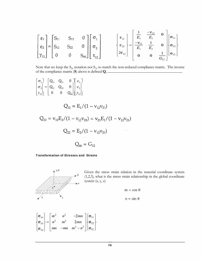
Note that we keep the S66 notation not S33 to match the non-reduced compliance matrix. The inverse of the compliance matrix (S) above is defined Q, _______________________________________.
⎥⎥⎥
⎦
⎤
⎢⎢⎢
⎣
⎡
⎥⎥⎥
⎦
⎤
⎢⎢⎢
⎣
⎡=
⎥⎥⎥
⎦
⎤
⎢⎢⎢
⎣
⎡
12
2
1
66
2212
1211
12
2
1
0000
γεε
τσσ
QQQQQ
Transformation of Stresses and Strains
Given the stress strain relation in the material coordinate system (1,2,3), what is the stress strain relationship in the global coordinate system (x, y, z)

71
Note that the engineering strain must be converted to tensorial strain in order to use the ________________________________________ [θ].
Alternately, the strain can be transformed directly by using a different transformation matrix:
It is now possible to determine the stress strain relationship in terms of the x-cordinate:

72
Note that there are additional terms in the Q bar matrix (Q16, and Q26) which relate ______________________________________________________________________ and vice versa. This effect of a shear strain resulting from an extensional stress is shown below.

73
Example
Calculate the Q bar matrix for each ply in a [0/90]S laminate if each ply in the laminate is a glass/epoxy lamina with a 70% fiber volume fraction. Assume the modulus of glass and matrix to be Ef=85 GPa, Em=3.4 GPa, νLTf=0.36, νm=0.30, Gf=35.42 GPa, Gm=1.308 GPa
74
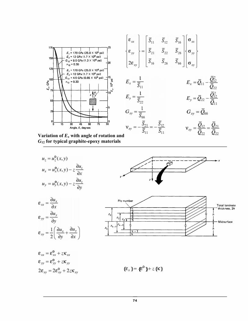
Variation of Ex with angle of rotation and G12 for typical graphite-epoxy materials

75
where

76
Laminate elastic constants for high-modulus graphite-epoxy system, [±θ]s

77
Example
Assuming the composite in the previous example, with each ply thickness equal to 0.3 mm and a loading of:
o Calculate the laminate stiffness [A,B,D] Matrix.
o Find the midplane strains [εx0, εy0, γxy0] and curvatures [κx, κy, κxy].
o Find the maximum strains and stresses in the material direction (1, 2, 3) for each ply.
{ }
{ } m/mN432
N/m300700500
−⎪⎭
⎪⎬
⎫
⎪⎩
⎪⎨
⎧=
⎪⎭
⎪⎬
⎫
⎪⎩
⎪⎨
⎧=
M
N

78
Special Laminates:
Recall that the strains and curvatures are related to applied loads through the ABD matrix:
In the general case this can result in __________________________________________ between bending, extension, torsion, and shear as illustrated below:
(from Barbero Intro to Composite Design)
In the general case, application of a load in one direction can make all 6 strains and curvatures terms non-zero. Several special laminates can be designed based on ____________________________ to eliminate some of these couplings by forcing the respective ABD matrix elements to be zero.
⎪⎪⎪⎪
⎭
⎪⎪⎪⎪
⎬
⎫
⎪⎪⎪⎪
⎩
⎪⎪⎪⎪
⎨
⎧
⎥⎥⎥⎥⎥⎥⎥⎥
⎦
⎤
⎢⎢⎢⎢⎢⎢⎢⎢
⎣
⎡
=
⎪⎪⎪⎪
⎭
⎪⎪⎪⎪
⎬
⎫
⎪⎪⎪⎪
⎩
⎪⎪⎪⎪
⎨
⎧
xy
y
x
xy
y
x
xy
y
x
xy
y
x
DDDBBBDDDBBBDDDBBBBBBAAABBBAAABBBAAA
MMMNNN
κκκγεε
0
0
0
662616662616
262212262212
161211161211
662616662616
262212262212
161211161211

79
_________________________________________ Laminates
• Description: For every layer at +θ, there is another at -θ, and for each 0° layer there is a 90° layer
• Example: __________________________________________
• Characteristics:
– Qbar16(θ )= -Qbar16(-θ)
– Qbar26(θ )= -Qbar26(-θ)
• Important characteristics:
– A16=A26=0
• Mechanical characteristic:
– no ____________________________________ coupling.
Symmetric Laminates
• Layers of the same material, thickness, and orientation are symmetrical w.r.t. to _____________________________________.
• Example: [+θ/- θ /- θ /+ θ]
– both balanced and symmetric
• Important characteristics:
– Bij=0
• Mechanical characteristics
– no ___________________________________________ coupling
Antisymmetric Laminates
• Pairs of layers of opposite orientation but the same material and thickness symmetrical w.r.t .middle surface of laminate.

80
• Example: [+θ /- θ /+ θ /- θ]
• Important characteristics:
– ______________________
– ______________________
• Not easy to analyze since B16 and B26 coupling terms are non-zero
Quasi-isotropic Laminates
• A laminate that behaves like an isotropic plate
• in-plane is similar to isotropic plates
• bending stiffness is different from isotropic plates
• Given by
– where k is the layer number; N=total layers (>=3), q0 is arbitrary initial angle
• Equal number of plies at
– 0, 45, -45, 90 or
– 0, 60, -60
• A matrix _________________________________
• B & D matrices are not
• Mechanical uses…..
0θπθ +=Nk
k

81
Cross-Ply and Angle-Ply Laminates
• cross-ply: 0° and 90° layers only
– 16 and 26 entries for A and D =0
– Easy for analysis if symmetric also, i.e., B=0
• angle-ply: ± θ ° layers only
– symmetric or antisymmetric balanced laminate
– symmetric: __________________________
– antisymmetric: _________________________

82
Lamina Failure Criterion: Many different failure theories have been suggested based on measured strengths in the __________
___________________________________________. Three of the most popular strength criteria
are:________________________ ________________________ ______________________ .
These failure theories recognize that most composite materials have different strengths in
_________________ and __________________.

83
Lamina failure theories can be classified as:
(1) ______________________________________________________
• No interaction among different stress components on failure is considered
• Examples: Max stress and Max strain
(2) ______________________________________________________
• All stress components are included in one expression (failure criterion)
• Examples: Tsai-Hill and Tsai-Wu theories
Maximum Stress Failure Criterion
The max stress criterion assumes that failure occurs when any one of the in-plane stresses attains its limiting value independent of the other components of stress.

84
Maximum Strain Failure Criterion
The max strain criterion assumes that failure occurs when any one of the in-plane reaches its ultimate value in uniaxial tension, compression, or pure shear.
Tsai-Wu Failure Criterion
Analogous to von-Mises stress criterion for isotropic materials, Tsai and Wu proposed a theory by assuming the existence of a ___________________________ in the stress space. The criterion takes the following form for plane stress:

85
Failure under combined stress is assumed to occur when _________________________ of the above equation is equal to or greater than one. All of the parameters (except F12) can be expressed in terms of basic strengths.
F12 can be estimated from the following relationship.
The Tsai-Wu criterion has been found to be quite accurate in predicting strength and is widely used.