COMPOSITE CRUSH SIMULATION – EMERGING TECHNOLOGIES … · COMPOSITE CRUSH SIMULATION – EMERGING...
12
COMPOSITE CRUSH SIMULATION – EMERGING TECHNOLOGIES AND METHODOLOGIES COMPOSITE CRUSH SIMULATION – EMERGING TECHNOLOGIES AND METHODOLOGIES Graham Barnes Engenuity Limited, UK Stuart Nixon SIMULIA, UK Marc Schrank SIMULIA, USA THEME Composites KEYWORDS Composites, Carbon, Laminate, Layup, Crush, Crashworthiness, Occupant Safety, Vehicle Crash, Collapse, Energy Absorption, Energy Management, Composite Impact, Crash Simulation, Lightweight, Minimum Weight, Low Emissions, Failure, Sled, Aerospace, Automotive SUMMARY In the quest to lower environmental impact while maintaining vehicle performance, automakers and aerospace companies are knocking on the same door – that is, increasing use of composite materials in order to reduce structural mass. It can be expected that material costs will drop considerably over the next few to several years, as the capacity to produce such materials begins to catch up with the growing demand. The benefits of using these materials are well-documented, including their substantial capacity to absorb energy in an impact scenario. Composite structures generally behave much differently than their metallic equivalents in a crash event when subjected to large compressive and dynamic forces. Whereas a metal structure will typically undergo large plastic deformations to absorb the kinetic energy of the event, a well-engineered composite member subjected to large axial compression will pulverize in a progressive manner from one end to the other as the “crush front” moves along Visit the SIMULIA Resource Center for more customer examples. Visit the SIMULIA Resource Center for more customer examples.
Transcript of COMPOSITE CRUSH SIMULATION – EMERGING TECHNOLOGIES … · COMPOSITE CRUSH SIMULATION – EMERGING...
COMPOSITE CRUSH SIMULATION – EMERGING TECHNOLOGIES
AND METHODOLOGIES
COMPOSITE CRUSH SIMULATION – EMERGING
TECHNOLOGIES AND METHODOLOGIES
Graham Barnes
Engenuity Limited, UK
Stuart Nixon
SIMULIA, UK
Marc Schrank
SIMULIA, USA
THEME
Composites
KEYWORDS
Composites, Carbon, Laminate, Layup, Crush, Crashworthiness, Occupant
Safety, Vehicle Crash, Collapse, Energy Absorption, Energy Management,
Composite Impact, Crash Simulation, Lightweight, Minimum Weight, Low
Emissions, Failure, Sled, Aerospace, Automotive
SUMMARY
In the quest to lower environmental impact while maintaining vehicle
performance, automakers and aerospace companies are knocking on the same
door – that is, increasing use of composite materials in order to reduce
structural mass. It can be expected that material costs will drop considerably
over the next few to several years, as the capacity to produce such materials
begins to catch up with the growing demand. The benefits of using these
materials are well-documented, including their substantial capacity to absorb
energy in an impact scenario.
Composite structures generally behave much differently than their metallic
equivalents in a crash event when subjected to large compressive and dynamic
forces. Whereas a metal structure will typically undergo large plastic
deformations to absorb the kinetic energy of the event, a well-engineered
composite member subjected to large axial compression will pulverize in a
progressive manner from one end to the other as the “crush front” moves along
Visit the SIMULIA Resource Center for more customer examples.
Visit the SIMULIA Resource Center for more customer examples.
COMPOSITE CRUSH SIMULATION – EMERGING TECHNOLOGIES
AND METHODOLOGIES
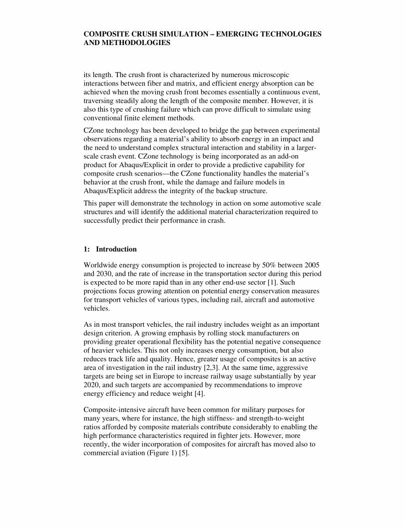
its length. The crush front is characterized by numerous microscopic
interactions between fiber and matrix, and efficient energy absorption can be
achieved when the moving crush front becomes essentially a continuous event,
traversing steadily along the length of the composite member. However, it is
also this type of crushing failure which can prove difficult to simulate using
conventional finite element methods.
CZone technology has been developed to bridge the gap between experimental
observations regarding a material’s ability to absorb energy in an impact and
the need to understand complex structural interaction and stability in a larger-
scale crash event. CZone technology is being incorporated as an add-on
product for Abaqus/Explicit in order to provide a predictive capability for
composite crush scenarios—the CZone functionality handles the material’s
behavior at the crush front, while the damage and failure models in
Abaqus/Explicit address the integrity of the backup structure.
This paper will demonstrate the technology in action on some automotive scale
structures and will identify the additional material characterization required to
successfully predict their performance in crash.
1: Introduction
Worldwide energy consumption is projected to increase by 50% between 2005
and 2030, and the rate of increase in the transportation sector during this period
is expected to be more rapid than in any other end-use sector [1]. Such
projections focus growing attention on potential energy conservation measures
for transport vehicles of various types, including rail, aircraft and automotive
vehicles.
As in most transport vehicles, the rail industry includes weight as an important
design criterion. A growing emphasis by rolling stock manufacturers on
providing greater operational flexibility has the potential negative consequence
of heavier vehicles. This not only increases energy consumption, but also
reduces track life and quality. Hence, greater usage of composites is an active
area of investigation in the rail industry [2,3]. At the same time, aggressive
targets are being set in Europe to increase railway usage substantially by year
2020, and such targets are accompanied by recommendations to improve
energy efficiency and reduce weight [4].
Composite-intensive aircraft have been common for military purposes for
many years, where for instance, the high stiffness- and strength-to-weight
ratios afforded by composite materials contribute considerably to enabling the
high performance characteristics required in fighter jets. However, more
recently, the wider incorporation of composites for aircraft has moved also to
commercial aviation (Figure 1) [5].
COMPOSITE CRUSH SIMULATION – EMERGING TECHNOLOGIES
AND METHODOLOGIES
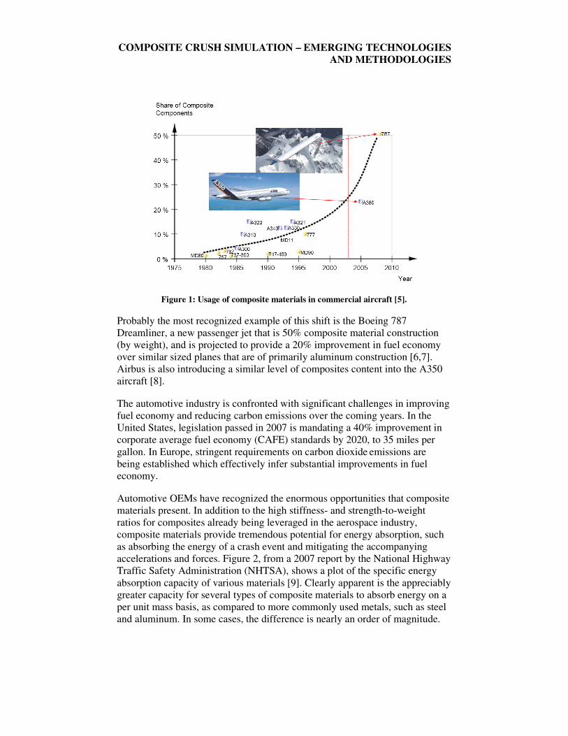
Figure 1: Usage of composite materials in commercial aircraft [5].
Probably the most recognized example of this shift is the Boeing 787
Dreamliner, a new passenger jet that is 50% composite material construction
(by weight), and is projected to provide a 20% improvement in fuel economy
over similar sized planes that are of primarily aluminum construction [6,7].
Airbus is also introducing a similar level of composites content into the A350
aircraft [8].
The automotive industry is confronted with significant challenges in improving
fuel economy and reducing carbon emissions over the coming years. In the
United States, legislation passed in 2007 is mandating a 40% improvement in
corporate average fuel economy (CAFE) standards by 2020, to 35 miles per
gallon. In Europe, stringent requirements on carbon dioxide emissions are
being established which effectively infer substantial improvements in fuel
economy.
Automotive OEMs have recognized the enormous opportunities that composite
materials present. In addition to the high stiffness- and strength-to-weight
ratios for composites already being leveraged in the aerospace industry,
composite materials provide tremendous potential for energy absorption, such
as absorbing the energy of a crash event and mitigating the accompanying
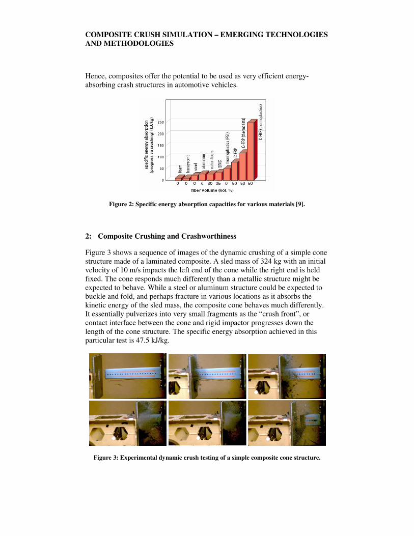
accelerations and forces. Figure 2, from a 2007 report by the National Highway
Traffic Safety Administration (NHTSA), shows a plot of the specific energy
absorption capacity of various materials [9]. Clearly apparent is the appreciably
greater capacity for several types of composite materials to absorb energy on a
per unit mass basis, as compared to more commonly used metals, such as steel
and aluminum. In some cases, the difference is nearly an order of magnitude.
COMPOSITE CRUSH SIMULATION – EMERGING TECHNOLOGIES
AND METHODOLOGIES
Hence, composites offer the potential to be used as very efficient energy-
absorbing crash structures in automotive vehicles.
Figure 2: Specific energy absorption capacities for various materials [9].
2: Composite Crushing and Crashworthiness
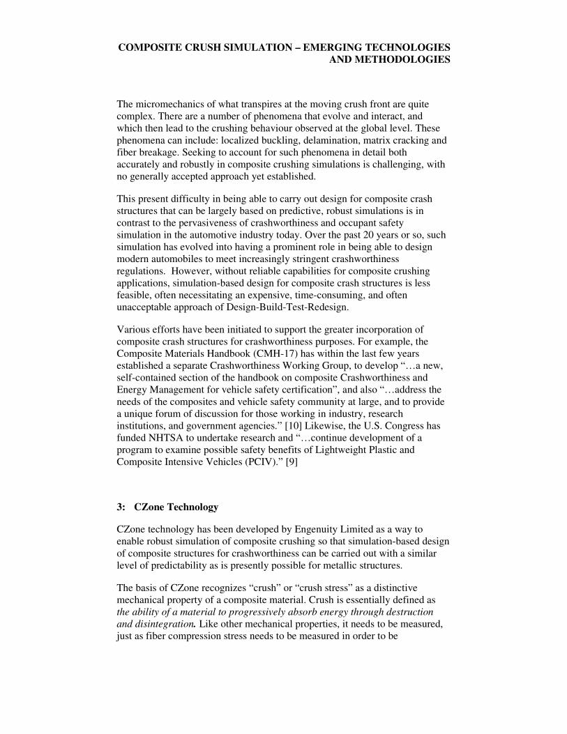
Figure 3 shows a sequence of images of the dynamic crushing of a simple cone
structure made of a laminated composite. A sled mass of 324 kg with an initial
velocity of 10 m/s impacts the left end of the cone while the right end is held
fixed. The cone responds much differently than a metallic structure might be
expected to behave. While a steel or aluminum structure could be expected to
buckle and fold, and perhaps fracture in various locations as it absorbs the
kinetic energy of the sled mass, the composite cone behaves much differently.
It essentially pulverizes into very small fragments as the “crush front”, or
contact interface between the cone and rigid impactor progresses down the
length of the cone structure. The specific energy absorption achieved in this
particular test is 47.5 kJ/kg.
Figure 3: Experimental dynamic crush testing of a simple composite cone structure.
COMPOSITE CRUSH SIMULATION – EMERGING TECHNOLOGIES
AND METHODOLOGIES
The micromechanics of what transpires at the moving crush front are quite
complex. There are a number of phenomena that evolve and interact, and
which then lead to the crushing behaviour observed at the global level. These
phenomena can include: localized buckling, delamination, matrix cracking and
fiber breakage. Seeking to account for such phenomena in detail both
accurately and robustly in composite crushing simulations is challenging, with
no generally accepted approach yet established.
This present difficulty in being able to carry out design for composite crash
structures that can be largely based on predictive, robust simulations is in
contrast to the pervasiveness of crashworthiness and occupant safety
simulation in the automotive industry today. Over the past 20 years or so, such
simulation has evolved into having a prominent role in being able to design
modern automobiles to meet increasingly stringent crashworthiness
regulations. However, without reliable capabilities for composite crushing
applications, simulation-based design for composite crash structures is less
feasible, often necessitating an expensive, time-consuming, and often
unacceptable approach of Design-Build-Test-Redesign.
Various efforts have been initiated to support the greater incorporation of
composite crash structures for crashworthiness purposes. For example, the
Composite Materials Handbook (CMH-17) has within the last few years
established a separate Crashworthiness Working Group, to develop “…a new,
self-contained section of the handbook on composite Crashworthiness and
Energy Management for vehicle safety certification”, and also “…address the
needs of the composites and vehicle safety community at large, and to provide
a unique forum of discussion for those working in industry, research
institutions, and government agencies.” [10] Likewise, the U.S. Congress has
funded NHTSA to undertake research and “…continue development of a
program to examine possible safety benefits of Lightweight Plastic and
Composite Intensive Vehicles (PCIV).” [9]
3: CZone Technology
CZone technology has been developed by Engenuity Limited as a way to
enable robust simulation of composite crushing so that simulation-based design
of composite structures for crashworthiness can be carried out with a similar
level of predictability as is presently possible for metallic structures.
The basis of CZone recognizes “crush” or “crush stress” as a distinctive
mechanical property of a composite material. Crush is essentially defined as
the ability of a material to progressively absorb energy through destruction
and disintegration. Like other mechanical properties, it needs to be measured,
just as fiber compression stress needs to be measured in order to be
COMPOSITE CRUSH SIMULATION – EMERGING TECHNOLOGIES
AND METHODOLOGIES
implemented in a finite element analysis simulation. Crush stress provides the
ongoing resistance when a portion of the composite structure is destroyed
against an impacting body, and it is this resistance that effectively becomes the
input force into the rest of the finite element model.
CZone technology is being made available commercially within the Abaqus
finite element software suite, in particular Abaqus/Explicit, an explicit
dynamics solver used across several industries for various applications,
including crashworthiness and occupant safety. The integration of CZone
within the framework of a commercial finite element software suite has the
noteworthy benefit that the wide range of features and functionality already
available in the commercial software package can be used in conjunction with
the specialized crushing simulation capabilities of CZone.
4: Calibration of Crush Stress
The crush stress mechanical property required for CZone usage can be
obtained through various test methods. The most feasible and cost-effective is
crush testing of coupons extracted from flat plaques or sheets of the candidate
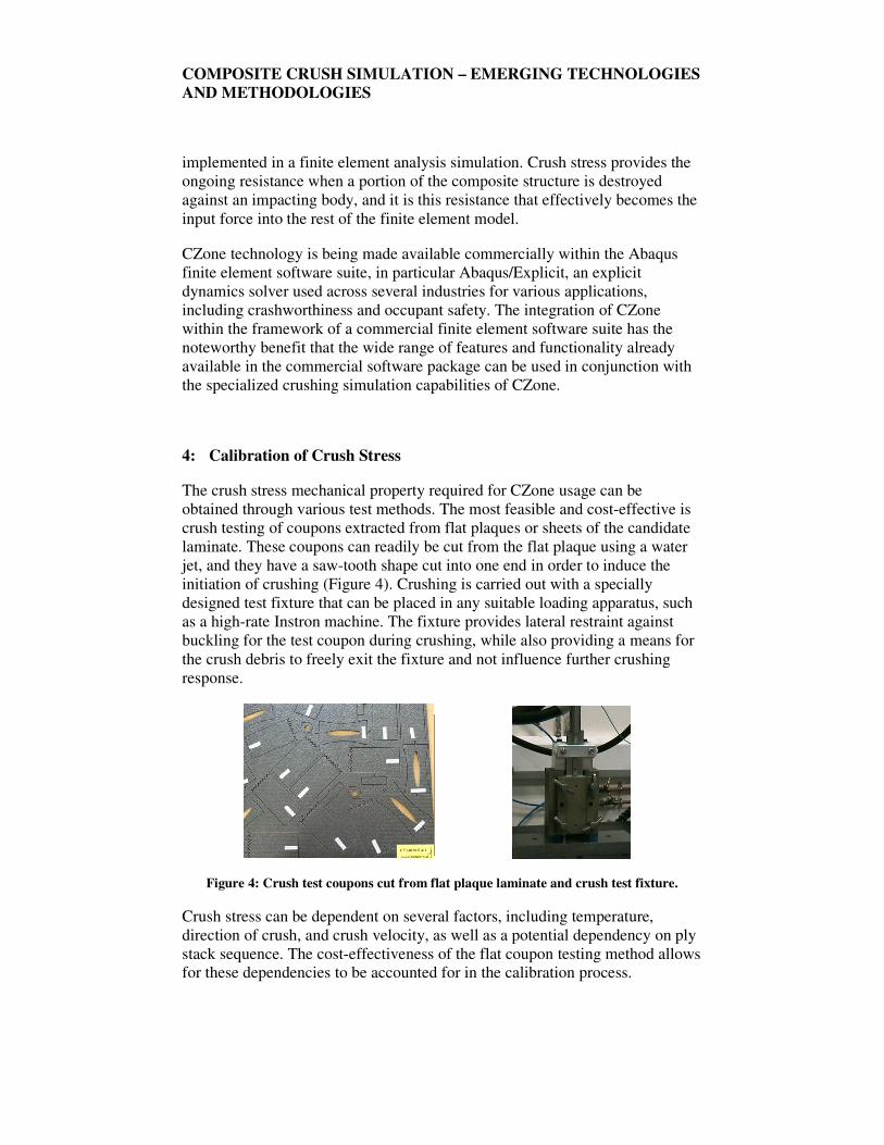
laminate. These coupons can readily be cut from the flat plaque using a water
jet, and they have a saw-tooth shape cut into one end in order to induce the
initiation of crushing (Figure 4). Crushing is carried out with a specially
designed test fixture that can be placed in any suitable loading apparatus, such
as a high-rate Instron machine. The fixture provides lateral restraint against
buckling for the test coupon during crushing, while also providing a means for
the crush debris to freely exit the fixture and not influence further crushing
response.
Figure 4: Crush test coupons cut from flat plaque laminate and crush test fixture.
Crush stress can be dependent on several factors, including temperature,
direction of crush, and crush velocity, as well as a potential dependency on ply
stack sequence. The cost-effectiveness of the flat coupon testing method allows
for these dependencies to be accounted for in the calibration process.

COMPOSITE CRUSH SIMULATION – EMERGING TECHNOLOGIES
AND METHODOLOGIES
Some recent experimental evidence suggests that crush stress for certain
composite materials exhibits an influence of geometry. In relatively flat regions
of the structure ahead of the crush front (prior to crushing), partial
delamination between plies can occur, influencing the subsequent crush stress.
Whereas in geometries that have sufficient curvature normal to the crushing
direction, this delamination is suppressed, thereby enhancing the measured
crush stress. This difference in measured crush stress can be accommodated for
in crushing simulations by assigning appropriate crush stress values to regions
of the original composite structure that are either considered flat or curved.
Recent work to enhance the flat coupon test fixture by incorporating a pin
restraint device for the coupon seems to reasonably induce the same type of
delamination suppression as due to curved geometry.
Not all composite materials exhibit good crushing behavior, and CZone
technology is not intended for those materials that do not crush well. The flat
coupon test method can be used effectively to not only calibrate crush stress,
but also to screen candidate materials in order to assess their ability to sustain
crush. Two primary characteristics are monitored: the average crush stress over
the length or duration of crush, as well as the stability or consistency of the
crush stress. Three examples of ‘Good’, ‘Fair’, and ‘Poor’ crushability are
shown in Figure 5. For the example showing Poor crush characteristics, the
large variations in crush stress over the length or duration of the test indicate
large fragments of the coupon that break away during the test, with no
continuous crush front ever really being established, similar to the test coupon
also shown in this figure.
Figure 5: Examples of crushing characteristics exhibited by different composite
materials, along with test coupon exhibiting poor crush characteristics.
COMPOSITE CRUSH SIMULATION – EMERGING TECHNOLOGIES
AND METHODOLOGIES
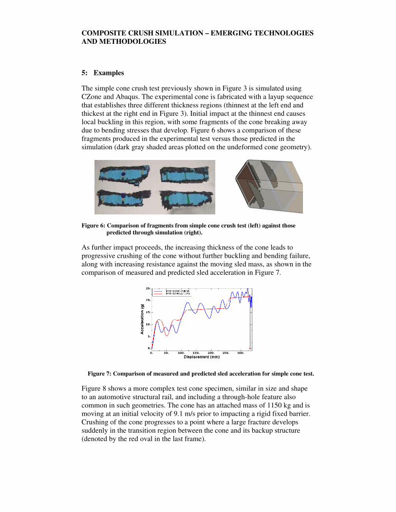
5: Examples
The simple cone crush test previously shown in Figure 3 is simulated using
CZone and Abaqus. The experimental cone is fabricated with a layup sequence
that establishes three different thickness regions (thinnest at the left end and
thickest at the right end in Figure 3). Initial impact at the thinnest end causes
local buckling in this region, with some fragments of the cone breaking away
due to bending stresses that develop. Figure 6 shows a comparison of these
fragments produced in the experimental test versus those predicted in the
simulation (dark gray shaded areas plotted on the undeformed cone geometry).
Figure 6: Comparison of fragments from simple cone crush test (left) against those
predicted through simulation (right).
As further impact proceeds, the increasing thickness of the cone leads to
progressive crushing of the cone without further buckling and bending failure,
along with increasing resistance against the moving sled mass, as shown in the
comparison of measured and predicted sled acceleration in Figure 7.
Figure 7: Comparison of measured and predicted sled acceleration for simple cone test.
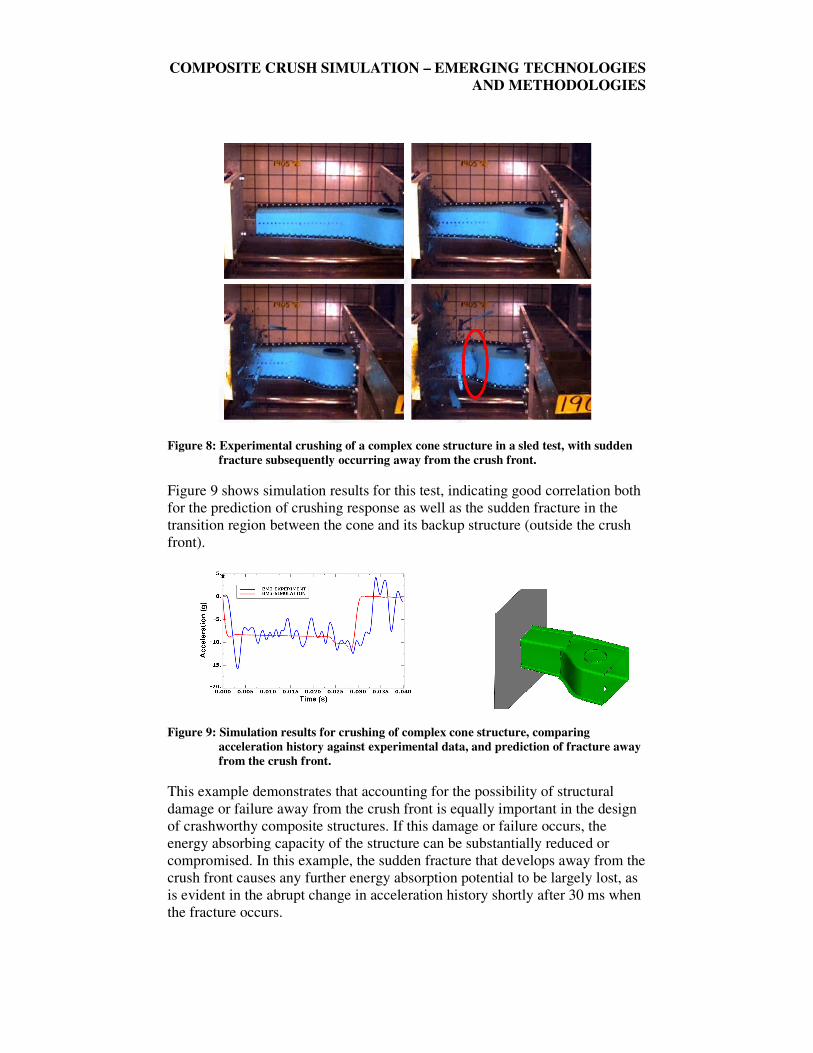
Figure 8 shows a more complex test cone specimen, similar in size and shape
to an automotive structural rail, and including a through-hole feature also
common in such geometries. The cone has an attached mass of 1150 kg and is
moving at an initial velocity of 9.1 m/s prior to impacting a rigid fixed barrier.
Crushing of the cone progresses to a point where a large fracture develops
suddenly in the transition region between the cone and its backup structure
(denoted by the red oval in the last frame).
COMPOSITE CRUSH SIMULATION – EMERGING TECHNOLOGIES
AND METHODOLOGIES
Figure 8: Experimental crushing of a complex cone structure in a sled test, with sudden
fracture subsequently occurring away from the crush front.
Figure 9 shows simulation results for this test, indicating good correlation both
for the prediction of crushing response as well as the sudden fracture in the
transition region between the cone and its backup structure (outside the crush
front).
Figure 9: Simulation results for crushing of complex cone structure, comparing
acceleration history against experimental data, and prediction of fracture away
from the crush front.
This example demonstrates that accounting for the possibility of structural
damage or failure away from the crush front is equally important in the design
of crashworthy composite structures. If this damage or failure occurs, the
energy absorbing capacity of the structure can be substantially reduced or
compromised. In this example, the sudden fracture that develops away from the
crush front causes any further energy absorption potential to be largely lost, as
is evident in the abrupt change in acceleration history shortly after 30 ms when
the fracture occurs.
COMPOSITE CRUSH SIMULATION – EMERGING TECHNOLOGIES
AND METHODOLOGIES
This example also demonstrates CZone technology working in concert with
existing features available in Abaqus/Explicit. CZone addresses the crushing
response at the interface between the cone structure and rigid wall, while
Abaqus/Explicit addresses all other aspects of the simulation, including the
potential for damage and fracture away from the crush front, in this case
utilizing the Tsai-Wu failure criterion [11].
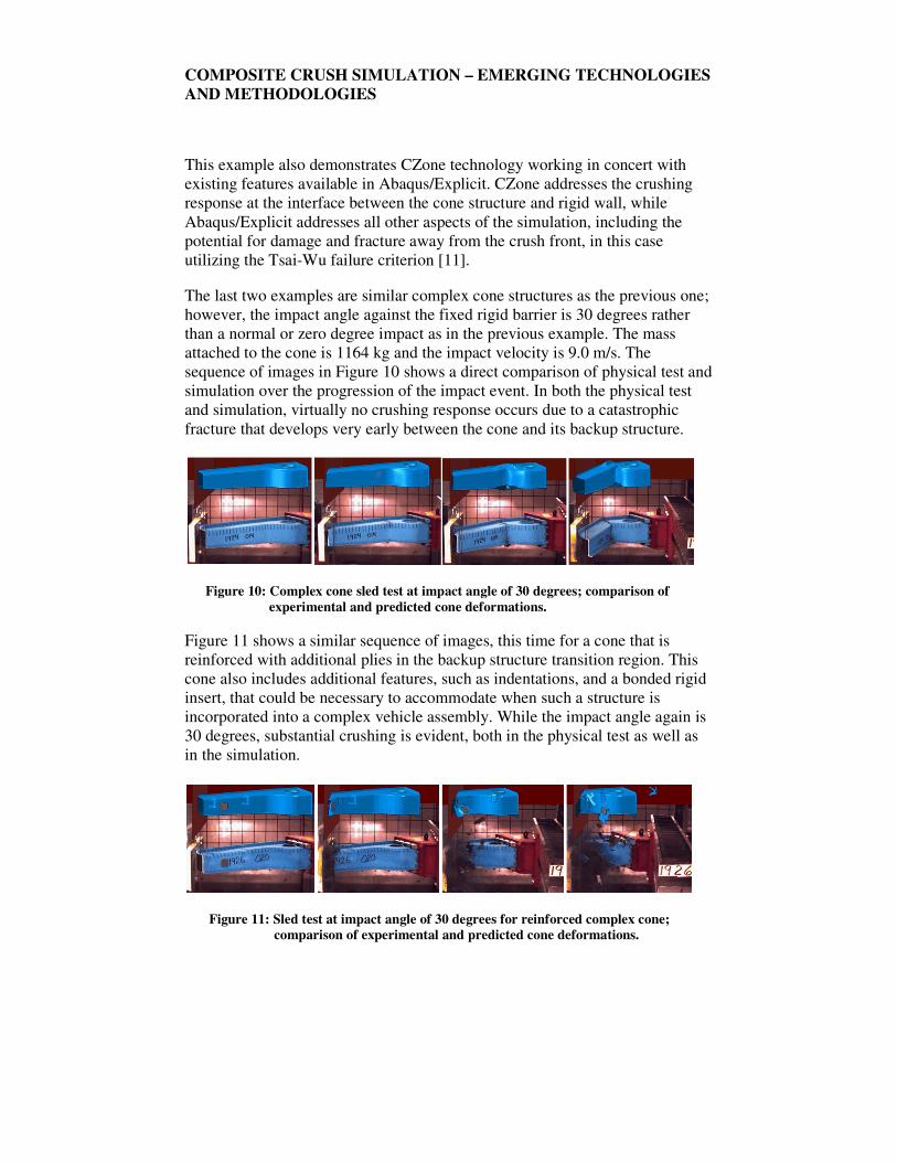
The last two examples are similar complex cone structures as the previous one;
however, the impact angle against the fixed rigid barrier is 30 degrees rather
than a normal or zero degree impact as in the previous example. The mass
attached to the cone is 1164 kg and the impact velocity is 9.0 m/s. The
sequence of images in Figure 10 shows a direct comparison of physical test and
simulation over the progression of the impact event. In both the physical test
and simulation, virtually no crushing response occurs due to a catastrophic
fracture that develops very early between the cone and its backup structure.
Figure 10: Complex cone sled test at impact angle of 30 degrees; comparison of
experimental and predicted cone deformations.
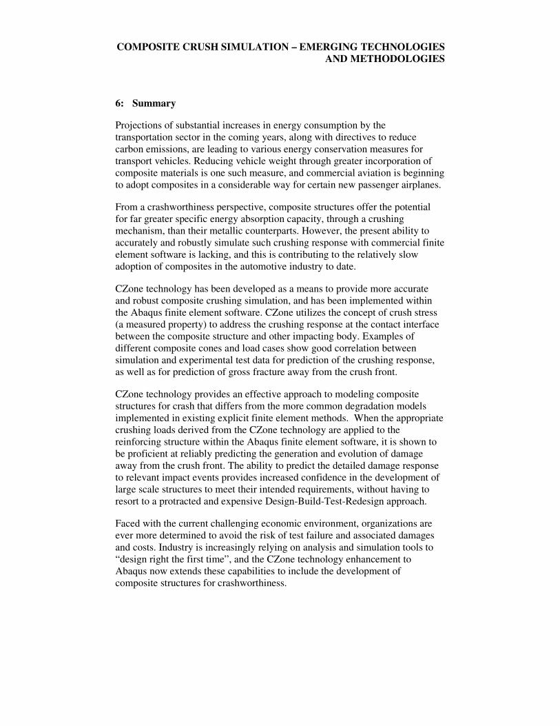
Figure 11 shows a similar sequence of images, this time for a cone that is
reinforced with additional plies in the backup structure transition region. This
cone also includes additional features, such as indentations, and a bonded rigid
insert, that could be necessary to accommodate when such a structure is
incorporated into a complex vehicle assembly. While the impact angle again is
30 degrees, substantial crushing is evident, both in the physical test as well as
in the simulation.
Figure 11: Sled test at impact angle of 30 degrees for reinforced complex cone;
comparison of experimental and predicted cone deformations.
COMPOSITE CRUSH SIMULATION – EMERGING TECHNOLOGIES
AND METHODOLOGIES
6: Summary
Projections of substantial increases in energy consumption by the
transportation sector in the coming years, along with directives to reduce
carbon emissions, are leading to various energy conservation measures for
transport vehicles. Reducing vehicle weight through greater incorporation of
composite materials is one such measure, and commercial aviation is beginning
to adopt composites in a considerable way for certain new passenger airplanes.
From a crashworthiness perspective, composite structures offer the potential
for far greater specific energy absorption capacity, through a crushing
mechanism, than their metallic counterparts. However, the present ability to
accurately and robustly simulate such crushing response with commercial finite
element software is lacking, and this is contributing to the relatively slow
adoption of composites in the automotive industry to date.
CZone technology has been developed as a means to provide more accurate
and robust composite crushing simulation, and has been implemented within
the Abaqus finite element software. CZone utilizes the concept of crush stress
(a measured property) to address the crushing response at the contact interface
between the composite structure and other impacting body. Examples of
different composite cones and load cases show good correlation between
simulation and experimental test data for prediction of the crushing response,
as well as for prediction of gross fracture away from the crush front.
CZone technology provides an effective approach to modeling composite
structures for crash that differs from the more common degradation models
implemented in existing explicit finite element methods. When the appropriate
crushing loads derived from the CZone technology are applied to the
reinforcing structure within the Abaqus finite element software, it is shown to
be proficient at reliably predicting the generation and evolution of damage
away from the crush front. The ability to predict the detailed damage response
to relevant impact events provides increased confidence in the development of
large scale structures to meet their intended requirements, without having to
resort to a protracted and expensive Design-Build-Test-Redesign approach.
Faced with the current challenging economic environment, organizations are
ever more determined to avoid the risk of test failure and associated damages
and costs. Industry is increasingly relying on analysis and simulation tools to
“design right the first time”, and the CZone technology enhancement to
Abaqus now extends these capabilities to include the development of
composite structures for crashworthiness.
COMPOSITE CRUSH SIMULATION – EMERGING TECHNOLOGIES
AND METHODOLOGIES
REFERENCES
1. Energy Information Administration, International Energy Outlook 2008,
Report No. DOE/EIA-0484(2008), September 2008
2. INGLETON, S., FOUND, M.S., and ROBINSON, A.M. – Design of
composite vehicle end structures in railway rolling stock. Experimental
Techniques and Design in Composite Materials 4, Ed. Found, M.S.,
Taylor & Francis, 2002
3. NewRail, The Research Requirements of the Transport Sectors to
Facilitate an Increased Usage of Composite Materials. Part III: The
Composite Material Research Requirements of the Rail Industry,
COMPOSIT Thematic Network, June 2004
4. European Rail Research Advisory Council, Strategic Rail Research
Agenda 2020, May 2007
5. EADS Deutschland GmbH, The Research Requirements of the Transport
Sectors to Facilitate an Increased Usage of Composite Materials. Part I:
The Composite Material Research Requirements of the Aerospace
Industry, COMPOSIT Thematic Network, June 2004
6. Boeing Company, http://www.boeing.com
7. SMOCK, D., Boeing 787 Dreamliner Represents Composites Revolution,
Design News, June 4, 2007
8. EADS/Airbus, http://www.airbus.com
9. National Highway Traffic Safety Administration, A Safety Roadmap for
Future Plastics and Composites Intensive Vehicles, Report No. DOT HS
810 863, November 2007
10. Composite Materials Handbook, http://www.cmh17.org/general.aspx
11. TSAI, S.W. and WU, E.M. – A general theory of strength for anisotropic
materials. Journal of Composite Materials. Vol. 5, pp. 58-80, 1971
Visit the SIMULIA Resource Center for more customer examples.