Component-Level Selection and Qualification for the Global ...
9
Component-Level Selection and Qualification for the Global Ecosystem Dynamics Investigation (GEDI) Laser Altimeter Transmitter Erich A. Frese a , Furqan L. Chiragh b , Robert Switzer a , Aleksey A. Vasilyev c , Joe Thomes d , D. Barry Coyle d , Paul R. Stysley d a ASRC Federal Space and Defense, 7000 Muirkirk Meadows Dr #100, Laurel, MD 20707 b Pinnacle Engineering & Management Solutions, 11779 Somerset Ave., Princess Anne, MD 21853 c Trident Vantage Systems, LLC, 10210 Greenbelt Rd #400, Lanham, MD 20706 d NASA Goddard Space Flight Center, Laser and Electro-Optics Branch, Greenbelt, MD 20771 ABSTRACT Flight quality solid-state lasers require a unique and extensive set of testing and qualification processes, both at the system and component levels to insure the laser's promised performance. As important as the overall laser transmitter design is, the quality and performance of individual subassemblies, optics, and electro-optics dictate the final laser unit’s quality. The Global Ecosystem Dynamics Investigation (GEDI) laser transmitters employ all the usual components typical for a diode-pumped, solid-state laser, yet must each go through their own individual process of specification, modeling, performance demonstration, inspection, and destructive testing. These qualification processes and results for the laser crystals, laser diode arrays, electro-optics, and optics, will be reviewed as well as the relevant critical issues encountered, prior to their installation in the GEDI flight laser units. Keywords: HOMER, LIDAR, GEDI, Altimeter, Laser, Nd:YAG INTRODUCTION The in-house development of the Global Ecosystem Dynamics Investigation (GEDI) laser transmitters required first- hand knowledge (when possible) of all optical component characteristics, margins, materials, manufacture, defects, and total performance in order to deliver the most reliable solid state lasers possible to the GEDI instrument. This 2 Figure 1. The GEDI laser is an oscillator-only design, developed around a conductively cooled, side-pumped zig zag Nd:YAG slab, optimized for maximum efficiency and inherent TEM00 operation. The laser is electro-optically Q-switched and uses a gaussian reflective output coupler to improve beam quality, reduce pointing jitter, and improve stability with an apertureless design. The laser is aligned, sealed, then flipped 180o to gain access to the thermal interface surface “under” the laser head.
Transcript of Component-Level Selection and Qualification for the Global ...

Component-Level Selection and Qualification for the Global Ecosystem Dynamics Investigation (GEDI) Laser Altimeter
Transmitter Erich A. Fresea, Furqan L. Chiraghb, Robert Switzera, Aleksey A. Vasilyevc, Joe Thomesd, D.
Barry Coyled, Paul R. Stysleyd
aASRC Federal Space and Defense, 7000 Muirkirk Meadows Dr #100, Laurel, MD 20707 bPinnacle Engineering & Management Solutions, 11779 Somerset Ave., Princess Anne, MD
21853 cTrident Vantage Systems, LLC, 10210 Greenbelt Rd #400, Lanham, MD 20706
dNASA Goddard Space Flight Center, Laser and Electro-Optics Branch, Greenbelt, MD 20771
ABSTRACT Flight quality solid-state lasers require a unique and extensive set of testing and qualification processes, both at the system and component levels to insure the laser's promised performance. As important as the overall laser transmitter design is, the quality and performance of individual subassemblies, optics, and electro-optics dictate the final laser unit’s quality. The Global Ecosystem Dynamics Investigation (GEDI) laser transmitters employ all the usual components typical for a diode-pumped, solid-state laser, yet must each go through their own individual process of specification, modeling, performance demonstration, inspection, and destructive testing. These qualification processes and results for the laser crystals, laser diode arrays, electro-optics, and optics, will be reviewed as well as the relevant critical issues encountered, prior to their installation in the GEDI flight laser units.
Keywords: HOMER, LIDAR, GEDI, Altimeter, Laser, Nd:YAG
INTRODUCTION The in-house development of the Global Ecosystem Dynamics Investigation (GEDI) laser transmitters required first-hand knowledge (when possible) of all optical component characteristics, margins, materials, manufacture, defects, and total performance in order to deliver the most reliable solid state lasers possible to the GEDI instrument. This 2
Figure 1. The GEDI laser is an oscillator-only design, developed around a conductively cooled, side-pumped zig zag Nd:YAG slab, optimized for maximum efficiency and inherent TEM00 operation. The laser is electro-optically Q-switched and uses a gaussian reflective output coupler to improve beam quality, reduce pointing jitter, and improve stability with an apertureless design. The laser is aligned, sealed, then flipped 180o to gain access to the thermal interface surface “under” the laser head.

year mission will be installed aboard the International Space Station and measure the 3D volume and structure of the Earth’s biomass using laser altimetry and digitized waveform recovery techniques.1 The GEDI laser transmitters, of which three will be on board, need to generate and send > 5 Billion laser pulses at > 10 mJ to the Earth, with sub-16 ns pulse widths, running at 242 pulses/sec, with high precision pointing knowledge and low jitter. Since the lasers will be operational for most part only over land masses, the total shot count is roughly 1/3 the total value of a 242 Hz system running continuously, or ~ 2.5 Billion shots/year/laser. The GEDI laser is an oscillator-only design, relatively large for a TEM00 transmitter, in lieu of a more typical master oscillator power amplifier (MOPA) design used for pulse energies >10 mJ. The Oscillator-only design demanded ~1/3 fewer optics than an equivalent MOPA design. This reduced optics count allowed us to focus more attention on critical component testing and selection for every part. In particular, we focussed much attention on the Nd:YAG laser slabs, the laser diode arrays (LDA), and the KD*P electro-optic Q-Switches (QS). We performed extensive testing on all of these components with customized testing hardware developed in-house. Our High Output Maximum Efficiency Resonator (HOMER) laser design provided the TRL-6 (technology readiness level) or “flight qualified” requirement needed for the GEDI project, with proven long life, high efficiency, and good stability.2,3
1. ND:YAG GAIN MEDIUM The heart of any solid state laser is its gain material. In this case, we baselined 1.1% doped, Nd:YAG slabs, side
pumped with seven, 4-bar laser diode arrays, each rated at
Figure 2. One of the GEDI laser design goals was for minimum part count. This reduced the man-power, costs, and schedule hits associated with the added procurement, characterization, testing, selection, and subassembly of the critical optical, electro-optical, and semiconductor components, associated with an equivalent MOPA design. The main components are: 1. End Mirror, 2. Risley Prism pair (X2), 3. Laser Head (slab, pump lens, & laser diodes), 4, Thin Film Polarizer, 5. Q-Switch, 6. 1/4 Wave Plate, 7. Gaussian Reflective Mirror, 8. Window and Mini-Beam Expander.
Figure 3a and 3b. The Nd:YAG GEDI slab is bonded to the MbCu heat sink for matched thermal expansion, which is mounted to the aluminum bridge structure, suspending the slab over the collimated laser diode arrays. The slab’s pump face is AR coated for 809 nm, with the bonded surface coated with TIR enhanced SiO2 and HR coated at 809 nm for double pass pumping.

100 W/bar at full power. The slabs are 5 x 2.6 x 100 mm zig zag slab, with 22 bounces, and coated for a double-pass pump length of 5.2 mm. The tip angles, slightly less than the effective Brewster’s angle, are 26.5o in order to reduce the slabs’ 2.6 mm axis to ~ 2 mm, in an attempt to match the effective width of the interior “collimated” pump beam. This helps to produce a symmetrical pump region as well as use the slabs’ effective zig-zag plane aperture (Y-axis) to hold the cavity mode structure to TEM00.4 With a Brewster’s angle tip, the laser cavity would produce a shorter gain length, requiring greater pump powers, producing higher thermal lensing, and the possibility of TEM01 beam.
1.1. Gain Medium (Slab) Testing Method & Performance
The testing of the slabs was performed on a Class 100 clean flow bench for the Engineering Test Unit (ETU) and a Class 10,000 clean room for the flight slabs. Figures 3a and 3b show details on the Nd:YAG slab manufacture and its mounting structure for low stress heat removal. Each slab went through an extensive acceptance and testing criteria due to the design’s high aspect ratio (length:thickness) and difficulty to manufacture. The final tip-tip length is set only after the final thickness and final polish is set onto long side faces during manufacture. Only then the final tip-tip length is calculated from this measured thickness, tip angle, and optical index. This is why each slab has a specific length, within the calculated specification from the drawings. These dimensions, with the absolute optical index of its origin Nd:YAG boule, determines how “clean” a 1064 nm test beam travels through the slab’s zig zag path.
For passive optical testing, we used a highly-polarized collimated fiber coupled laser diode carefully controlled between 1-10 mW. The beam profiles, with and without slab, were captured using a CCD and beam imaging software. A schematic and photograph of the slab characterization setup is shown in Figure 4. Verification testing was completed on both non-bonded and bonded slabs to verify the slab’s platform, quality of workmanship, and in-
Figure 4a and 4b. The Nd:YAG GEDI slab passive optical testing system is shown. This provided high resolution data on the slabs’ performance under pre- and post-bonding cases, measured the effective clear aperture (the result of tip angle, thickness, length, and optical index), and andy issues the pump-related 808 nm coatings may have on the lasers’ 1064 nm gain zig-zag path.
Figure 5a and 5b. The laser slab optical test setup details and beam quality results are shown. Precision slab placement, both bonded and unbounded, provide the capability for effective aperture and material quality assessment as well.

house bonding continuity. An X-Y translation stage was used to align the slab into the diode laser’s beam path. Great care needed to be taken when aligning the slab such that the probe beam was passed through the slab cleanly, the beam and slab was absolutely level and on the same plain, and that any distortion or pointing change would be due to slab quality alone and not the testing apparatus. By analyzing images of the probe beam with the slab in and out of the beam path, we were able to determine if the manufactured dimensions were within the limits needed for our lasers. The optical power exiting the output facet of the slab was documented and used to determine the unused insertion power. This loss was also a key factor in determining the acceptance of slabs for flight purposes.
Finally, the effective clear aperture was measured by locating the probe beams’ centroid with and without slabs, and translating slabs vertically to calculate the range of clip-free position. These data told us if the slab was “too short” or “too long” tip-tip for that specific unit’s thickness and tip angle. Figure 5 shows a bonded slab during testing and CCD images of the probe beam with and without the slab.
2. LASER DIODE ARRAY (LDA) An understanding of Laser Diode Array (LDA) degradation has important consequences for laser applications such as LIDAR and understanding the lifetime of the lasers they are in. Since the laser diodes are the optical power
Figure 6. The selected laser diode arrays are 4-bar stacks of 100 W rated bars emitting 808 nm. These are industry standard ”G packages” connectively cooled with 7 stacks aligned in series optically and electrically.
Figure 7. Laser Diode Array Characterization station, including emitter-level IR facet imaging, real-time optical and electrical performance tracking, and precision thermal feedback and control.
source for the GEDI laser, their reliable operation is critical to the performance of the entire instrument.5 In the selection process we tested and aged our LDAs for over 3.2 Billion shots in order to select diodes for our flight lot, well over a 1 year equivalent value of 2.5 Billion. The GEDI laser baselined a set of seven, 4-bar stacks of Quasi-CW laser diode arrays. Each set of 4 bars were mounted in a standard G-package, or back cooled assembly, with the 4 bars electrically in series. Using a custom in-house testing LDA testing apparatus, we stressed the LDAs under operational conditions for extended periods of time in order to measure and trend their performance and any detectable variations. We monitored energy, wavelength, and all hotspots on the LDAs emitting facets. Collected data was analyzed in order to create groupings of LDAs that would create optimal pumping configurations for laser performance. The 4-bar arrays were delivered with a 400-um pitch, with 60 emitters/bar and a total maximum output of 100W at 100 A. Each emitter was 150-um in length and spacing between emitters was 10-um as shown in Figure 6.
2.1. Laser Diode Array (LDA) Testing Method & Performance
In order to meet GEDI mission requirements, the testing requirements for the LDAs called for operation at a current of 55A, a baseline current pulse width of 65 us, a repetition rate of 242 Hz, and an operational temperature of 35 °C. These drive parameters are well below the peak rated conditions of 100 A and 200 us, but to increase reliability and lifetime, a maximum derating set point was desired over power. As an initial baseline, the LDAs were operated at a current of 55A, a current pulse width of 200 us, a repetition rate of 30 Hz and an operational temperature of 25 °C before and after testing to detail any changes in the LDAs’ benchmark performances.
Additionally, Images were taken of the LDAs using a 50X microscope before and after testing to check for degradation of the diode bars. The custom, in-house imaging system provided the ability to scan across multiple diodes arrays under operation to take real time emission data, as seen in Figure 7. With this setup we were able to test six LDAs simultaneously by translating our detector setup from LDA to LDA. The data collected allowed us to
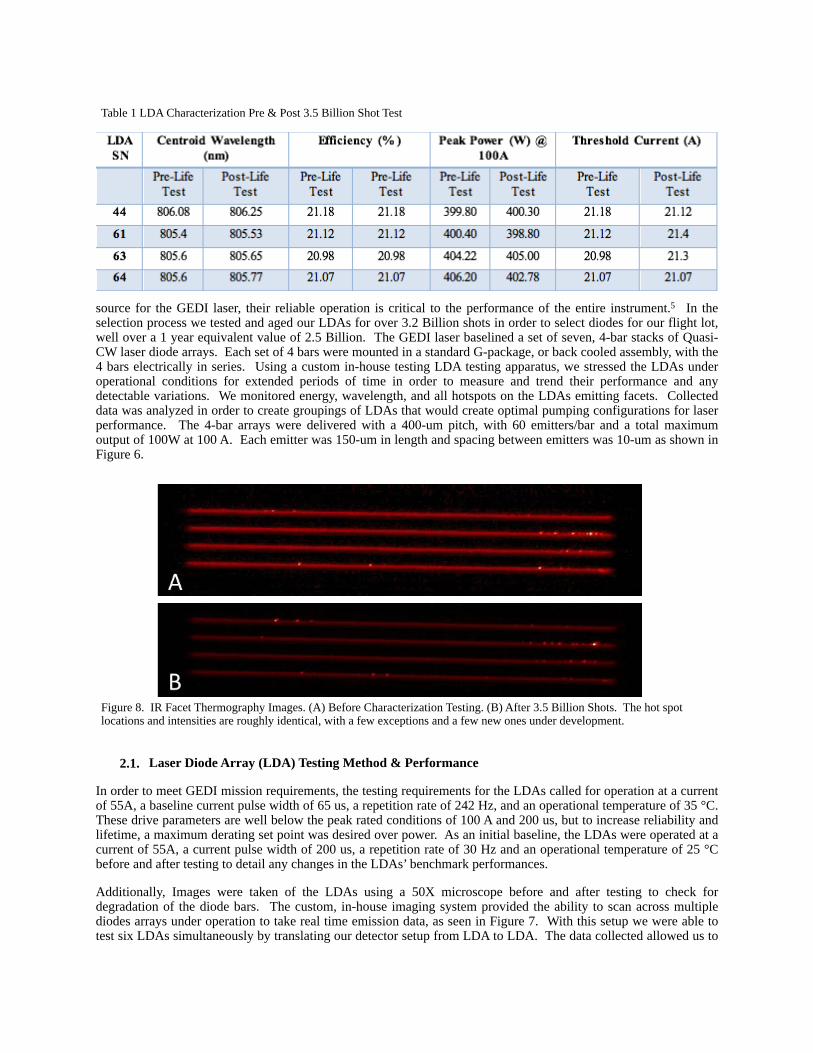
Figure 8. IR Facet Thermography Images. (A) Before Characterization Testing. (B) After 3.5 Billion Shots. The hot spot locations and intensities are roughly identical, with a few exceptions and a few new ones under development.
Table 1 LDA Characterization Pre & Post 3.5 Billion Shot Test

analyze P-I curves and efficiency, LDA spectrum via image spectroscopy, near-field imaging of the LDAs, IR facet thermography, and polarization. The ability to monitor the wavelengths of multiple LDAs provided extremely useful when it came to selecting LDA combinations in order to optimize the pumping of your gain media.
Pre- and post-characterization of the LDAs performance, including centroid wavelength, efficiency, peak power, and threshold current, showed that after > 3.5 Billion pulses, all tested devices were nearly unchanged. The IR facet thermography allowed us to monitor any hot spots on the LDA bars as shown in Figure 8. Extreme hot spots typically indicate potential failure points for bars operating for long periods of time. These hot spots can shift the operational characteristics of each LDA, usually in wavelength. Additionally, if the number of hot spots increase over time, this could create thermal lensing effects that will degrade the coupling of the LDAs to their gain media and change the solid state laser’s performance over time. Through these observations, we were able to measure the hot spot temperatures as well as the number of spots. After 3.5 Billion shots on the LDAs, we did not notice an increase of hot spots, but the maximum temperature of the hot spots did increase. This is not of too much concern to us because we will be operating the LDAs well below the operational values of our test.6 We were able to operate our test sample of LDAs for > 3.5 Billion shots at GEDI laser parameters while seeing minimal changes to their required performance. The 3.5 Billion shots value was more than expected to be completed during GEDI’s 2-year scheduled mission lifetime.
3. OPTICS INSPECTION AND TESTING 3.1. Passive Optics
Optical components are key to the cavity of the laser’s performance, so each item had to be verified and validated in dimension, material, coating, and performance. This was done through a process that included visual and microscopic inspection, optical throughput testing, active testing, polarization contrast ratio analysis (when applicable), and dimensional analysis. Each optic was visually inspected with a microscope using at least 5X magnification under general ambient lighting. This was to test for any surface of material imperfections from the manufacture or any damage due to shipment or packaging. A UV “black” light was also used for detecting foreign debris or contamination, such as finger prints, abnormal features, or contaminants in the coatings. If any was found, filtered nitrogen gas was used to remove the contaminates off of the optical surfaces. Back-lighting the optics was helpful for pinholes and defects in the optical coatings. Since no optic is “perfect” under magnification, each components’ acceptance criteria was set and evaluated by the laser team and each optic was graded based on the optics purpose, and labeled pass or fail.
Dimensional analysis was performed to measure the physical dimensions of each optical component to its mechanical drawing. One might think the overall dimensions of laser optics are not as important as the coating and surface qualities. However, these optics are all bonded in a dedicated Titanium cell or mount with carefully pre-
Figure 9. GEDI Laser 7 x 4-bar pump arrangement on laser head, shown undergoing test operation. (808 nm shows as “pink” on a digital camera.) Note the G4 heat sinks are slightly staggered from side to side. This alignment was performed under a low-power microscope to align each array’s adjacent bar emitter, as the bars are not installed exactly in the heat sink’s center.

determined bond lines and thicknesses. These gaps are critical to minimize stresses on the optics as the lasers undergo thermal cycling in environmental testing as well as in orbit. The bonding material, bonding locations, and material quantities were selected carefully to further minimize latent stress or any movement over temperatures. Thus, tight physical tolerances were important to the total acceptance data of all the cavity optics, and not simply their optical performance. The main evaluated dimensions were height, and width for square optics, diameter for circular optics, and thickness for all.
Finally, laser induced damage threshold testing was performed on a spare or sample optic with each coating or manufacturing run. For example, if a total quantity of thirty, 0.5o risley wedges were procured, then eventually delivered in four batches over the course of their manufacture, then four separate samples were pulled from each batch for LIDT testing. If successful, only then could that lot be allowed to undergo further testing. The LIDT data was calculated for each intra-cavity surface throughout the oscillator in two methods; as the nominal fluence and intensity level for 10 ns-level pulses, as well as the peak intensities that would be periodically present for the 100 ps regime due to longitudinal mode beating, inherent in every non-single frequency Q-Switched laser. If the LIDT testing for any delivered batch of optical components, including laser slabs, failed our minimal specified levels, that set was marked as “fail”, and replaced by the manufacturer. Ideally, the LIDT results would arrive before the in-house characterization studies began for each delivery, but this was not always the case. Ultimately, these physical and operational parameters, with margin and tolerances, were calculated and designed for each laser optic and used for the initial procurements and as well as the final grading criteria. The final data sets were compiled for each optic by type, by the inspection team, and evaluated by the lead laser engineer for final pass or fail determination. Only then would we set aside components for flight opto-mechanical bonding and sub-assembly efforts.
3.2. Electro-optic Q-Switch
Another important optical element in the GEDI laser cavity is the electro-optic Q-Switch (QS). Unlike any other optic in the system, the QS arrives from the manufacturer in an “assembled” form; a teflon cylinder with hermetically sealed quartz windows, and an electrically contacted cylindrical KD*P is crystal suspended inside. By applying a short high voltage (HV) signal across this capacitive device, via electrodes protruding from the housing, the laser cavity’s net polarization is precisely controlled and likewise, a fast and powerful “Q-Switched” laser pulse is produced. Next to the Nd:YAG laser slab, the Q-Switch is the most critical optic in the GEDI laser cavity. Acceptance testing the QS units meant we needed to develop custom tests unlike the other optics.
Figure 10a & 10b. Passive optical loss testing for the general laser optic components, and the active birefringence performance testing of the QS, respectively. All the optics went through the characterization profile (shown left) before their respective performance test tailored to its specific purpose; such as the 14 wave plate (polarization rotation) or output coupler (reflectivity and curvature). These test, combined with attention the dimensional, coating, surface, and quality of assembly (where applicable), determined the final flight unit selections for all components.
1064nmLaser Diode
1064nmIsolator
30:70 Beam Splitter Cube
Beam Expander
635nm Laser Diode
635nm Collimator
Tip/Tilt stage with 1064nm Collimator
Mirror
Q Switch
Optical Detector 1 (Source Monitor)
50:50 Beam Splitter
Iris
Polarizing Cube
¼ Wave Plate
Iris
APD Photodiode
O-ScopeQ Switch HV Driver
Active Contrast RatioTesting: Q-Switch

Figure 10b shows the intrinsic, or passive, contrast ratio testing setup which helped define the crystalline structure of the QS itself. Initially, the optic was removed from the setup and the test laser diode’s power was minimized using the power meters and a ½ wave-plate. This was recorded as the background signal value. This test was then performed again with the QS inserted in the path and adjustments made in pitch, yaw, and roll until the power meter signal was minimized. The setup in Figure 12 is the active contrast ratio setup. For this test, DC and pulsed high voltage was applied to the QS and a photodiode monitored the throughput laser energy. Monitoring the photodiode on an Oscilloscope we adjusted the high voltage driver to the QS in order to maximize the exiting laser energy. This provides us with the QS’ contrast ratio during its active state, of HV state.
Most critical was the QS’s passive and active birefringence (contrast ratio), as well as electrostatic sensitivities to clamping forces on it’s perimeter. Essentially, the performance of the QS device was sensitive to hard tightly the cell was “squeezed” in its mounting structure. To minimize this effect, we were careful to design a non-conductive cylindrical clamping mount which only squeezed circumferentially on the QS end rings and not in the center. This insured no added electro-static stresses were applied to the crystal under cavity alignment and component torquing. However, if over torqued, this effect was readily witnessed, even with the precision mounting hardware, and much care was taken under final assembly. To mitigate passive birefringent effects from fastener torquing, we performed this action while under laser cavity operation, and monitored the laser pulse’s net polarization contrast ratio in real time while each fastener on the QS mount was installed.
Finally, the QS required independent 3-axis rotational alignment adjustment capability, independent of the intracavity risley pairs used for end mirror alignment. The final QS mounting structure, adapted from important performance performance and characterization results discussed earlier, was critical in the final success of the GEDI laser. A combination of Titanium (for rigidity and strength) as well as Ultem (for high voltage isolation and low thermal expansion) was used for the final design. Roll, pitch, and yaw of the QS cell was adjustable by hand, with dedicated sets of fasteners with pre-load and capability for reliable adjustment.
4. CONCLUSIONS
The low part count of the oscillator-only GEDI laser design was important in allowing maximum effort in the qualification of every laser component and the in-house testing of as many characteristics as possible. Even the simplest of optics, such as the enclosure windows, were subjected to rigorous processes of verification of promised specifications and expected performance. These processes described above were customized for each optic’s
Figure 11a, 11b, 11c. The KD*P Q-Switch assembly was possibly the most difficult laser component to qualify for flight. Its unique sensitivities to alignment, temperature, and clamping forces required a highly customized mounting assembly. The mount was made of Ultem (low thermal expansion, and low conductivity) and titanium base, or cradle. Figure “c” shows the QS assembly as it sits in the GEDI laser cavity, between the thin film polarizer (near) and the 1/4 wave plate (far).

specific task for successful laser operation. Furthermore, we were able to gain high confidence in each part selected and the overall expectation that each part will successfully perform over the GEDI mission lifetime of 2 years, plus margin.
The laser slab’s high aspect ratio proved difficult to manufacture but we were able to work closely with the suppliers and fine tune their process for achieving the necessary parallelism and dimensional tolerances required. The LDAs were thoroughly tested in house, both in a dedicated batch for lifetime, as well as the flight units and operated specifically at the designed specifications for GEDI laser operation. The QS cells went through extreme acceptance testing, mostly because of their inherent environmental sensitivities, but also to show these devices would survive and perform over the extremes of rocket launch and space deployment. Overall, the early removal of unsatisfactory optics prevented the activities of further costly and unneeded testing, as well as probable issues arising during final flight laser assembly. The accumulated in-house test data across all components proved critical in the final selection and “grading” of the accepted optics, and allowed the final laser transmitters to meet or exceed the GEDI requirements.
REFERENCES
1. “Global Ecosystem Dynamics Investigation Lidar”, <https://eospso.nasa.gov/missions/global-ecosystem-dynamics-investigation-lidar>
2. Coyle, Donald, et. al., "Efficient, reliable, long-lifetime, diode-pumped Nd:YAG laser for space-based vegetation topographical altimetry," Applied Optics 43, 5236-5242 (2004).
3. Stysley, Paul, et. al, "Long term performance of the High Output Maximum Efficiency Resonator (HOMER) laser for NASA ׳s Global Ecosystem Dynamics Investigation (GEDI) lidar," Optics & Laser Technology 68, 67-72 (2015).
4. Melanie Ott, Donald Barry Coyle, John Canham, and Henning Leidecker, “Qualification and Issues with Space Flight Laser Systems and Components,” International Society for Optical Engineering Conference on Lasers and Applications in Science and Engineering, Solid State Lasers XV, Technology and Devices, SPIE Vol. 6100 (2006).
5. Anthony W. Yu, Mark A. Stephen, Steven X. Li, George B. Shaw, Antonios Seas, Edward Dowdye, Elisavet Troupaki, Peter Liiva, Demetrios Poulios, Kathy Mascetti, "Space laser transmitter development for ICESat-2 mission," Proc. SPIE 7578, Solid State Lasers XIX: Technology and Devices, 757809 (2010).
6. Paul R. Stysley, D. Barry Coyle, Greg B. Clarke, Erich Frese, Gordon Blalock, Peter Morey, Richard B. Kay, Demetrios Poulios, Michael Hersh, "Laser production for NASA's Global Ecosystem Dynamics Investigation (GEDI) lidar," Proc. SPIE 9832, Laser Radar Technology and Applications XXI, 983207 (13 May 2016);