Complete Rawl Product Catalogue
154
Product Catalogue Cl/SfB Xt6 October 2007
Transcript of Complete Rawl Product Catalogue

Product Catalogue
RA
WL
FIX
ING
SP
rod
uct C
ata
log
ue
Octo
be
r 20
07
Rawlplug LtdSkibo Drive
Thornliebank Industrial Estate
Glasgow G46 8JR, UK
Sales Tel: +44 (0) 141 638 2255
Sales Fax: +44 (0) 141 273 2333
Export Sales Fax: +44 (0) 141 273 2336
Technical Tel: +44 (0) 1530 812857
Technical Fax: +44 (0) 1530 812862
Email: [email protected] or [email protected]
Rawlplug Ireland LtdUnit 14, Park West Industrial
Dublin 12, Ireland
Tel: +353 (0) 1 629 8479
Fax: +353 (0) 1 623 7053
Rawl France SarlZI Mitry-Compans
BP 536
12-14 Rue Marc Seguin
77295 Mitry-Mory cedex, France
Tel: +33 1 60 21 50 20
Fax: +33 1 64 67 19 84
e-mail: [email protected]
Rawl Scandinavia ABLysingsvägen 18
593 53 Västervik, Sweden
Tel: +46 (0) 490 30660
Fax: +46 (0) 490 30670
Koelner-Rawlplug Middle East FZEP.O. Box 261024
Jebel Ali Free Zone
Dubai
United Arab Emirates
Tel: + 971 4 8839501
Fax: + 971 4 8839502
e-mail: [email protected]
Website: www.rawlplug.com
® Rawl and Rawlplug are registered trade marks of RAWLPLUG Ltd.
Cl/SfB Xt6
October 2007
OKLADKA.indd 1OKLADKA.indd 1 2007-10-16 11:25:362007-10-16 11:25:36

2 Technical Advisory Service Tel: +44 (0) 1530 812 857, Fax: +44 (0) 1530 812 862
The Technical Department off ers a variety of services to specifi ers, distributors and users of Rawl Fixings products.
Technical AdviceFixing specialists will off er immediate advice and
recommendations over the telephone.
Field EngineersAre available to off er fi xing advice at your offi ce
or on site.
Site TestingRawl Fixings engineers will conduct site testing to ensure the appropriate fi xing is specifi ed and used. A detailed report is provided with recom-mendations.
Technical (CPD) SeminarsWe will be pleased to provide technical seminars, to ensure personnel involved in the specifi cation and selection of structural anchors are up-to-date with developments and standards.
Contractor TrainingRawl Fixings engineers will be pleased to carry out practical training for contractors to ensure anchors are installed correctly.
Technical Calculation Software An innovative calculation CD ROM from Rawl
Fixings. Allows calculations and product selections
to be made in concrete. Includes both mechanical and chemical anchor
solutions. For your free CD, please e-mail Rawl Fixings
To ensure that we continue to meet the future requirements of the industry,
Rawlplug has a policy of continuous product development supported by
extensive design and test centre facilities. Rawlplug therefore reserves the
right to modify product designs without prior notice. Rawlplug also reserves
the right to modify information contained within this guide without notify-
ing existing holders of the document. While this document gives guidance
relating to the use and nature of the products and variety of applications, the
ultimate responsibility for correct selection of a product for a specifi c appli-
cation must lie with the customer. Rawlplug recommendations are made in
good faith but do not constitute a guarantee.
OKLADKA.indd 2OKLADKA.indd 2 2007-10-16 11:25:452007-10-16 11:25:45
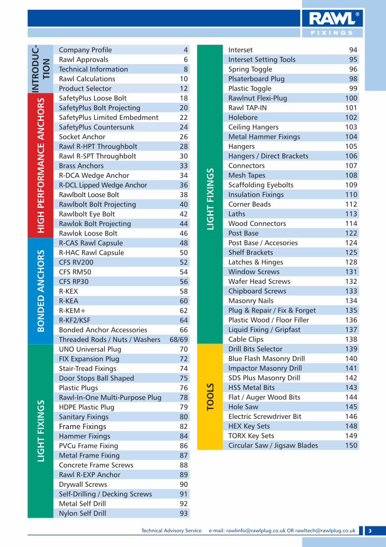
3Technical Advisory Service e-mail: [email protected] OR [email protected]
INTR
OD
UC
-TI
ON
Company Pro� le 4Rawl Approvals 6Technical Information 8Rawl Calculations 10Product Selector 12
HIG
H P
ERFO
RMA
NC
E A
NC
HO
RS
SafetyPlus Loose Bolt 18SafetyPlus Bolt Projecting 20SafetyPlus Limited Embedment 22SafetyPlus Countersunk 24Socket Anchor 26Rawl R-HPT Throughbolt 28Rawl R-SPT Throughbolt 30Brass Anchors 33R-DCA Wedge Anchor 34R-DCL Lipped Wedge Anchor 36Rawlbolt Loose Bolt 38Rawlbolt Bolt Projecting 40Rawlbolt Eye Bolt 42Rawlok Bolt Projecting 44Rawlok Loose Bolt 46
BON
DED
AN
CH
ORS
R-CAS Rawl Capsule 48R-HAC Rawl Capsule 50CFS RV200 52CFS RM50 54CFS RP30 56R-KEX 58R-KEA 60R-KEM+ 62R-KF2/KSF 64Bonded Anchor Accessories 66Threaded Rods / Nuts / Washers 68/69
LIG
HT
FIX
ING
S
UNO Universal Plug 70FIX Expansion Plug 72Stair-Tread Fixings 74Door Stops Ball Shaped 75Plastic Plugs 76Rawl-In-One Multi-Purpose Plug 78HDPE Plastic Plug 79Sanitary Fixings 80Frame Fixings 82Hammer Fixings 84PVCu Frame Fixing 86Metal Frame Fixing 87Concrete Frame Screws 88Rawl R-EXP Anchor 89Drywall Screws 90Self-Drilling / Decking Screws 91Metal Self Drill 92Nylon Self Drill 93
Interset 94
LIG
HT
FIX
ING
S
Interset Setting Tools 95Spring Toggle 96Plsaterboard Plug 98Plastic Toggle 99Rawlnut Flexi-Plug 100Rawl TAP-IN 101Holebore 102Ceiling Hangers 103Metal Hammer Fixings 104Hangers 105Hangers / Direct Brackets 106Connectors 107Mesh Tapes 108Scaffolding Eyebolts 109Insulation Fixings 110Corner Beads 112Laths 113Wood Connectors 114Post Base 122Post Base / Accesories 124Shelf Brackets 125Latches & Hinges 128Window Screws 131Wafer Head Screws 132Chipboard Screws 133Masonry Nails 134Plug & Repair / Fix & Forget 135Plastic Wood / Floor Filler 136Liquid Fixing / Gripfast 137Cable Clips 138
TOO
LS
Drill Bits Selector 139Blue Flash Masonry Drill 140Impactor Masonry Drill 141SDS Plus Masonry Drill 142HSS Metal Bits 143Flat / Auger Wood Bits 144Hole Saw 145Electric Screwdriver Bit 146HEX Key Sets 148TORX Key Sets 149Circular Saw / Jigsaw Blades 150
RAWL_KATALOG_2007_2008.indb 3RAWL_KATALOG_2007_2008.indb 3 2007-10-15 14:26:102007-10-15 14:26:10

4 Technical Advisory Service Tel: +44 (0) 1530 812 857, Fax: +44 (0) 1530 812 862
HeritageFor 88 years, the Rawlplug brand
has been synonymous with
innovation, reliability and safety in
the development and manufacture
of construction anchors and ancillary
products.
In 1919, John J. Rawlings, a London builder, developed and
patented the first ever specialist wall fixing. His revolutionary Fibre
Plug was the product from which the modern range of Rawlplug
fixings was to develop.
The company expanded dramatically and today it is one of the
world’s leading fixing manufacturers with distribution on every
continent.
Innovation remains at the heart of Rawlplug’s success, including
significant developments of torque controlled anchors and bonded
anchor systems for safety critical applications.
High Quality ManufacturingRawlplug and Rawl Fixings products are manufactured using some
of the most advanced production facilities in the industry. Rawlplug
and Rawl Fixings anchors are renowned for their consistent high
quality and performance.
The company’s quality system is approved to BS EN ISO 9001: 2000
for design and manufacture.
The company also places great emphasis on providing a safe
working environment for its employees.
Link - up ®
Product ApprovalThe proven quality and performance of Rawlplug and Rawl Fixings
anchors is demonstrated by the numerous independent approvals that
Rawlplug and Rawl Fixings products carry. In fact, in 1999, Rawlplug
became the first UK manufacturer to obtain European approvals (ETA)
for the R-HPT and R-SPT throughbolt range.
Other international approvals include:
COMPANY PROFILE
RAWL_KATALOG_2007_2008.indb 4RAWL_KATALOG_2007_2008.indb 4 2007-10-15 14:26:242007-10-15 14:26:24

5Technical Advisory Service e-mail: [email protected] OR [email protected]
Technical Support ServiceRawlplug’s Technical Advisory Service offers free advice on the
correct selection and installation of anchors to distributors,
specifiers and users around the world. Staffed by qualified engineers
with many years of experience, the technical support service
provides:
� 24 hour access: available by phone, fax and internet
� Advice on anchor design and selection
� Advice on usage & application, including contractor training
� Recommendations on fixing solutions
� On site testing (mainly UK)
� Technical seminars
� Distributor training
This service is supported by field engineers available to visit design
offices and contractors at short notice.
Technical literature, and a CD-Rom design disc is available to
users, specifiers and distributors. Full up-to-date information on all
Rawlplug activities is available on the Rawlplug website
www.rawlplug.co.uk.
In addition, Rawlplug distributors are serviced by dedicated and
experienced customer support teams. Each team can provide
distributors and users with advice on:
� Product availability
� Pricing and order placement
� Order and despatch status
� Literature
� Quotations
� Product samples
Worldwide Distribution NetworkFast, reliable availability of Rawlplug and Rawl Fixings products is
guaranteed thanks to our extensive international network.
Rawlplug has subsidiaries in Scandinavia, Ireland, France & UAE.
Area sales managers cover all areas of the UK, Europe and the
Middle East providing distributor support, site training and advice.
Product Development &
Testing Facilities Achievement and maintenance of the numerous approvals is largely
due to the extensive technical facility at Rawlplug’s modern testing
centre in Glasgow. Equipped with 3D solid modelling technology,
finite element analysis systems and the latest testing equipment,
Rawlplug’s testing capability is amongst the best in the world.
COMPANY PROFILE
RAWL_KATALOG_2007_2008.indb 5RAWL_KATALOG_2007_2008.indb 5 2007-10-15 14:26:422007-10-15 14:26:42

6 Technical Advisory Service Tel: +44 (0) 1530 812 857, Fax: +44 (0) 1530 812 862
BackgroundOctober 1997 marked the first significant step in the development, selection
and use of structural and safety critical anchor bolts. The European
Commission adopted the first ever European Technical Approval Guideline
(ETAG) for any construction product.
ETAG 001, Parts 1 and 3 “Metal Anchors for use in Concrete”
These parts of the ETAG cover torque controlled anchors such as Rawl R-HPT
and Rawl R-SPT Throughbolts. Adoption of the ETAG 001 marked the first
stage of harmonisation of product approval systems throughout Europe.
This harmonisation has been sought after by manufacturers, specifiers and
end users for many years, allowing products to be compared on a like for like
basis and the free passage of products within Europe.
ETAG 001, Part 4 “Metal Anchors for use in Concrete”
Adopted in December 1998, it covers deformation controlled anchors such as
the Rawl Wedge Anchor (more commonly known as “drop-in” anchor).
ScopeETAG 001 covers all structural and safety relevant applications where there
is risk to human life or considerable economic consequence. It is extremely
difficult to clearly identify the applications where approved products should
be selected or which are covered by the scope of the ETAG.
Testing and AssessmentEuropean Technical Approvals (ETA’s) can only be awarded after satisfying the
demanding requirements of the comprehensive test programme described
within ETAG 001, “Metal Anchors for use in Concrete”.
Suitability tests determine the functionality of the anchor under the most
likely and extreme deviations from installation and service conditions. This
would include: variations in concrete strengths, tolerances of hole diameter,
deviations in installation torques, repeated and sustained loads, cracked
concrete and the subsequent movement of such cracks.
Admissible Service Condition tests are used to establish characteristic loads
(i.e. tensile, shear and combined), and all edge spacing distances when
installed in accordance with the manufacturers instructions.
Stringent assessment criteria are also applied to all tests. Load/displacement
graphs must show positive gradients with no sign of slipping of the anchor.
The mean ultimate load in all suitability tests must attain a given percentage
of the reference values obtained in the Admissible Service Condition tests and
all test results must have limited scatter.
The net effect of the new comprehensive range of tests and stringent
assessment criteria will reduce current load performances and increase the
edge distances and spacings for all products, in comparison with current
published and accepted performance.
ManufacturingThe manufacturer must also satisfy and demonstrate to an independent
control body that they have effective control of the manufacturing
specifications and processes for the approved product. This control is product
specific and is far more complex and detailed than the general BS EN ISO
9001:2000 specification. This ensures the highest quality is maintained for
these safety critical products, a policy which Rawlplug has always upheld.
CE MarkingTo affix CE marking to an anchor, it must have two important documents:
1) A European Technical Approval (ETA) in accordance with the ETAG 001
“Metal Anchors for use in Concrete”.
2) A certificate of attestation from an independent control body.
Only then can an anchor possess CE marking.
RAWL APPROVALS
RAWL_KATALOG_2007_2008.indb 6RAWL_KATALOG_2007_2008.indb 6 2007-10-15 14:26:572007-10-15 14:26:57

7Technical Advisory Service e-mail: [email protected] OR [email protected]
BenefitsETAG approved and CE marked products will enable specifiers, distributors,
contractors and end users to have the utmost confidence in specifying, selling
and installing these products, where safety and reliability are paramount and
where performance and quality can be assured.
Rawl FixingsRawlplug and Rawl Fixings have continued to develop their range of products
to meet these requirements to ensure their customers can satisfy current and
future market needs with new, improved anchors with increased safety.
Rawl Fixings has been awarded ETA approvals and CE marking for the new
range of Rawl R-HPT and Rawl R-SPT Throughbolts i.e. ETA’s 98/0003 and
05/0078 and certificates of attestation 0836-CPD-004 and 0836-CPD-003.
Rawlplug and Rawl Fixings were the first UK manufacturer of any construction
products to be awarded an ETA and CE marking.
This ensures that customers are supplied with world class products of the
highest quality and technical performance which can be independently
certified.
FutureThis new approach to approvals has led to unknown territory where there is
generally low awareness of the detail and on the impact it will have on the
use of these products. This particularly applies to the definition and the scope
of cracked concrete, structural and safety critical applications. To complicate
matters further each member state within the EC has still to prescribe a
transition period for their market place, whereby existing national approval
systems will run their course and eventually be superceded by the new
approach to ETA’s. This is likely to be a protracted and diverse procedure.
During this transition period national approvals will still be accepted,
although the performance data has been based on different testing and
assessment criteria. Direct comparison of performance data between approval
systems cannot be made. Therefore products which are currently used in the
market place can still be used during this transition period. This situation is
complex and confusing, but during this stage customers can rely on Rawlplug
and Rawl Fixings to provide guidance on selection and supply of approved
products to meet their requirements.
Rawlplug and Rawl Fixings continue to be represented on the working groups
which compile future guidelines and building regulations, thus ensuring that
their customers are kept up-to-date with current developments and that their
requirements are continuously considered.
Rawlplug Ltd. is proud to be a member of the Construction Fixings Association
(CFA) which represents major fixings suppliers within the UK
and whose aims are summarised in the phrase:
Ensuring Best Fixings Practice
The Association achieves this by:
e Publishing a series of free Guidance Notes*
e Contributing to the development of European Guidelines for
Technical Approval of anchors
e Being directly involved in the development of European and
British Standards
e Working with other influential bodies such as CIRIA and BBA to
improve the understanding and use of the fixings.
e Supporting specific industries in the development of guidelines
for their use of fixings.
All CFA Members are committed to providing technically proven products
manufactured to recognised Quality Assurance procedures and backed up
with comprehensive technical support services including performance data,
applications advice, site testing and training in the correct use of our products.
* Downloadable free from the website which also carries articles,
news and technical advice www.fixingscfa.co.uk
For more information contact:
The Secretary,
Construction Fixings Association65 Dean Street, Oakham, LE15 6AF
Tel & Fax 01664-474755email: [email protected]
RAWL APPROVALS
RAWL_KATALOG_2007_2008.indb 7RAWL_KATALOG_2007_2008.indb 7 2007-10-15 14:27:052007-10-15 14:27:05

8 Technical Advisory Service Tel: +44 (0) 1530 812 857, Fax: +44 (0) 1530 812 862
Fig.1
Fig.2
Fig.3
Fig.4
Direction of Loading
Slotted Holes in Fixture.When � xing anchors through slotted holes it is important to ensure that there is adequate surface contact between the washer and the � xture to guarantee a positive clamping force. If in doubt a square plate washer with a thickness of 3mm or greater would be recommended in place of the standard washer supplied.
Diamond Drilled Holes.When holes are formed in the structure using a diamond drilling system extra care is required to ensure that the holes are thoroughly cleaned by brushing and blowing at least three times. Also to create a key for the anchor, (particularly if a bonded anchor is installed), the sides of the hole should be roughened up by inserting a standard masonry bit into the hole attached to a hammer action drilling machine.A resin with minimal shrinkage such as Rawl R-KEX should be selected for diamond drilled holes.
The direction of the applied load must be considered to determine the most appropriate anchor. The tension and shear components must be less than the recommended load/design resistance in the direction concerned.
Tensile LoadsTensile loads are applied along the axis of the fixing (see fig. 1). Common examples include suspended ceiling applications and the suspension of mechanical services, pipework and ductwork etc.
Shear LoadsShear loads act at right angles to the axis of a fixing and directly against the face of the structural material (see fig. 2). Shear performance is governed mainly by the shear strength of the bolt material and compressive strength of the supporting substrate.
Oblique/Combined LoadsOblique loads are a combination of tension and shear components (see fig.3). If the angle of applied oblique load is within 10o of pure tension or pure shear, the safe working load for that direction may be assumed. Otherwise, the applied oblique load should be resolved into its shear and tensile components.
Offset LoadsOffset loads act at right angles to the fixing axis but are offset from the surface (see fig. 4). In this situation, the deflection of the bolt, due to bending, needs to be considered as well as the shear capacity of the anchor.
TECHNICAL INFORMATION
RAWL_KATALOG_2007_2008.indb 8RAWL_KATALOG_2007_2008.indb 8 2007-10-15 14:27:482007-10-15 14:27:48

9Technical Advisory Service e-mail: [email protected] OR [email protected]
Fig.5
Installation
Recommended Tightening TorquesIn torque controlled expansion anchors a clamping force is exerted through the fixture into the base material. The clamping force is directly proportional to the tightening torque. Tightening the anchor enables the expander to key into the surrounding substrate providing a secure fixing (see fig. 5).
Tightening to Rawl Fixings’ recommended tightening torques ensures that the clamping force is greater than the published safe working loads. These torques should not be exceeded as this may overstress the bolt and/or base material. Adjustable torque wrenches of the ‘break back’ type are recommended for setting fixings.
Expanding Fixings
Torque controlled anchors transmit expansion forces by locally
compressing the substrate. The forces are exerted at the point
of expansion, not over the whole length of the fixing.
On applying the load to the anchor, additional forces are exerted
as shown by the light blue area ie. concrete cone (see fig.6).
It is this projected area which relates to the performance of the
anchor. Therefore as the embedment depth is increased the larger
the cone and the greater the performance of the anchor (see fig.7).
Any reduction in the projected area, for example when anchors
are placed too close together or too near the edge of the concrete
(see fig.8 and fig. 9) will result in reduced performance and should
be avoided if possible.
Where unavoidable, the appropriate reduction factors shown
for reduced spacing or edge distance should be applied to the
recommended load/design resistance indicated for the anchor.
Fig.6
Fig.8Fig.7
Fig.9
TECHNICAL INFORMATION
Anchor choice may be affected by certain aspects of the installation, for instance the desirability of a through fixing. The fixture can then be used as a template, and the fixing made through nominal clearance holes without the need for the object to be removed and replaced.
Key PointsTo achieve published performance values, it is essential that all anchors are installed correctly in accordance with Rawl Fixings’ installation instructions. Some basic points to remember are:� Drill correct diameter hole, to the correct depth.� Clean the hole thoroughly. This is important for all anchors, but critical for bonded anchors.� Use the correct setting equipment and procedure.� Tighten to the recommended torque.
RAWL_KATALOG_2007_2008.indb 9RAWL_KATALOG_2007_2008.indb 9 2007-10-15 14:27:552007-10-15 14:27:55
10 Technical Advisory Service Tel: +44 (0) 1530 812 857, Fax: +44 (0) 1530 812 862
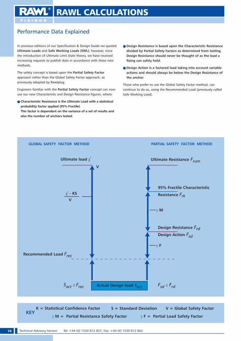
In previous editions of our Specification & Design Guide we quoted Ultimate Loads and Safe Working Loads (SWL), however, since the introduction of Ultimate Limit State theory, we have received increasing requests to publish data in accordance with these new methods.
The safety concept is based upon the Partial Safety Factor approach rather than the Global Safety Factor approach, as previously adopted by Rawlplug.
Engineers familiar with the Partial Safety Factor concept can now use our new Characteristic and Design Resistance figures, where:
e Characteristic Resistance is the Ultimate Load with a statistical probability factor applied (95% Fractile). This factor is dependent on the variance of a set of results and also the number of anchors tested.
e Design Resistance is based upon the Characteristic Resistance divided by Partial Safety Factors as determined from testing. Design Resistance should never be thought of as the load a fixing can safely hold.
e Design Action is a factored load taking into account variable actions and should always be below the Design Resistance of the anchor.
Those who prefer to use the Global Safety Factor method, can continue to do so, using the Recommended Load (previously called Safe Working Load).
Performance Data Explained
K = Statistical Confidence Factor S = Standard Deviation V = Global Safety Factor
� M = Partial Resistance Safety Factor � F = Partial Load Safety FactorKEY
GLOBAL SAFETY FACTOR METHOD
Ultimate Resistance Frum
95% Fractile Characteristic
Resistance Frk
Design Resistance FrdDesign Action Fsd
Recommended Load Frec
Fsd � FrdSact ��Frec
PARTIAL SAFETY FACTOR METHOD
� M
� F
Actual Design load Sact
����KS
V
-
V
Ultimate load �-
RAWL CALCULATIONS
RAWL_KATALOG_2007_2008.indb 10RAWL_KATALOG_2007_2008.indb 10 2007-10-15 14:27:592007-10-15 14:27:59

11Technical Advisory Service e-mail: [email protected] OR [email protected]
Combined Load (concrete only)When selecting an anchor, which will carry a combined load, ensure that the bolt size selected satisfies the following equations:
AF = Across flatsCcr,N = Characteristic edge distance in
tensionCcr,V = Characteristic edge distance in
sheard = Bolt thread sizeDcsk = Countersunk bolt head diameter
df = Hole diameter in fixturedo = Hole diameter in concreteDw = Washer diameterE = Diameter of eyeFd = Design loadFrec = Recommended loadFRu,m = Mean ultimate loadFRk = Characteristic load (95% fractile)
fuk = Ultimate tensile strengthH = Diameter of hookfyk
= Yield strengthhef = Effective embedment depth
(distance from surface to point of expansion)
hmin = Minimum substrate thicknessho = Minimum hole depthl = Bolt lengthlcsk = Countersunk head depthlg = Thread lengthNact = Applied tensile loadNrec = Recommended load in tensionNRd = Design resistance in tensionNRk = Characteristic resistance in tension
Nsd = Design action tensionS = Shield lengthScr = Characteristic edge distance
in tension & shearSw = Bolt head diameterTfix = Fixture thicknessTinst = Recommended torqueVact
= Applied shear loadVRk = Characteristic resistance in shearVRd = Design resistance in shearVrec = Recommended load in shearVsd
= Design action shear�M = Partial safety factor for material
�Q = Partial safety factor for actions
Glossary of abbreviations
Partial Method
Nsd
Nrd
+V
sd
Vrd
≤1.0
(Edge and spacing reduction factors, if applicable, should be applied to the tensile and shear design resistance loads.)
This calculation is not valid for shear.
Concrete Strength Calculation
x√Nrec
/ Nrd
in
30N/mm2 Concrete
Actual Concrete Strength
30
(Loads shown are for 30N/mm2 (C20/25) concrete. For other grades of concrete between 20 and 50N/mm2 where the anchor is in tension the load can be calculated using this formula.)
Note: The method of calculating combined loads in concrete has been revised in line with ETAG. The equation is calculated to the power of 1.5 and the result should be equal to or less than 1.0.
Installation Depth
Re-Bar/Resin Design Concept
Load
Ultimate Load
Minimum fuk
550N/mm2
Minimum fyk
460N/mm2
95%Fractile
��
�Q
FRu,m
FRk
Fd F
rec
NB Example of interpolationIf edge distance equals 45mm for an M8 stud then the edge factor will be equal to 50% of the difference between the edge factors for 40mm and 50mm.Example40mm edge factor = 0.850mm edge factor = 0.9ThereforeEdge factor for 45mm = 0.85
≤1.2
Global Method
(Edge and spacing reduction factors, if applicable, should be applied to the safe tensile and shear loads.) +
Nact
Nrec
Vact
Vrec
RAWL CALCULATIONS
≤1.0
1.5 1.5
1.5 1.5
RAWL_KATALOG_2007_2008.indb 11RAWL_KATALOG_2007_2008.indb 11 2007-10-15 14:28:122007-10-15 14:28:12

12 Technical Advisory Service Tel: +44 (0) 1530 812 857, Fax: +44 (0) 1530 812 862
DESCRIPTION ETA PAGE THREAD RANGE
HIG
H P
ERFO
RMA
NC
E A
NC
HO
RS
SafetyPlus Loosebolt 18 M8-M20
SafetyPlus Bolt Projecting 20 M8-M20
SafetyPlus Limited Embedment 22 M8-M16
SafetyPlus Countersunk 24 M8-M16
Socket Anchor 26 M8-M20
R-HPT Throughbolt � 28 M6-M20
R-SPT Throughbolt � 30 M6-M24
Brass Anchor 33 M5-M16
Wedge Anchor Pending 2007 34 M6-M20
Lipped Wedge Anchor Pending 2007 36 M6-M16
Rawlbolt Loose Bolt 38 M6-M24
Rawlbolt Bolt Projecting 40 M6-M24
Rawlbolt Eyebolt 42 M6-M12
Rawlok Bolt Projecting 44 M5-M12
Rawlok Loosebolt Incl St Stl 46 M6-M10
BON
DED
AN
CH
ORS
R-CAS 48 M8-M30
R-HAC 50 M8-M30
CFS RV200 Pending 2007 52 M8-M24
CFS RM50 54 M8-M24
CFS RP30 56 M8-M24
R-KEX 58 M8-M30
R-KEA 60 M8-M24
R-KEM + 62 M8-M24
R-KF2/R-KSF 64 M8-M24
Bonded Anchor Accessories 66
Threaded Rod, Nuts and Washers 68/69 M6-M20
LIG
HT
FIX
ING
S
UNO Universal Plug 70
FIX Expansion Plug 72
Stair-Tread Fixings 74
Door Stops Ball Shaped 75
Plastic Plugs 76
Rawl-In-One Multi-Purpose Plug 78
HDPE Plastic Plug 79
PRODUCT SELECTOR
RAWL_KATALOG_2007_2008.indb 12RAWL_KATALOG_2007_2008.indb 12 2007-10-15 14:28:222007-10-15 14:28:22

13Technical Advisory Service e-mail: [email protected] OR [email protected]
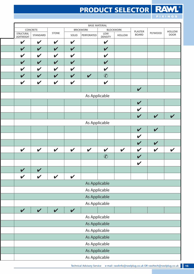
PRODUCT SELECTOR
BASE MATERIAL
CONCRETESTONE
BRICKWORK BLOCKWORKPLASTER BOARD PLYWOOD HOLLOW
DOORSTRUCTURAL LIGHTWEIGHT STANDARD SOLID PERFORATED LOW
DENSITY HOLLOW
� �
� �
� �
� �
� �
� � �
� � �
� � � � �
� �
� �
� � � � �
� � � � �
� � � � �
� � � � �
� � � � �
� �
� �
� �
� � � � � �
� � � � � � �
� �
� �
� � � � � �
� � � � � � �
As Applicable
As Applicable
� � � � � � � � � �
� � � � �
� � �
� � �
� � � �
� � � � � � �
� � � � �
RAWL_KATALOG_2007_2008.indb 13RAWL_KATALOG_2007_2008.indb 13 2007-10-15 14:30:322007-10-15 14:30:32

14 Technical Advisory Service Tel: +44 (0) 1530 812 857, Fax: +44 (0) 1530 812 862
DESCRIPTION ETA PAGE THREAD RANGE
LIG
HT
FIX
ING
S
Sanitary Fixings 80
Frame Fixings 82
Hammer Fixings 84
PVCu Frame Fixing 86
Metal Frame Fixings 87
Concrete Frame Screws 88
Rawl R-EXP Anchor 89
Drywall Screws 90
Self-Drilling / Decking Screws 91
Metal Self Drill 92
Nylon Self Drill 93
Interset 94 M4-M8
Interset Setting Tools 95
Spring Toggle 96 M3-M6
Plasterboard Plug 98
Plastic Toggle 99
Rawlnut Flexi-Plug 100 M3-M12
Rawl TAP-IN 101
Holebore 102
Ceiling Hangers 103
Metal Hammer Fixings 104
Hangers 105/106
Direct Brackets 106
Connectors 107
Mesh Tapes 108
Scaffolding Eybolts 109
Insulation Fixings 110
Corner Beads 112
Laths 113
Wood Connectors 114
Post Base 122
Post Base / Accesories 124
Shelf Brackets 125
PRODUCT SELECTOR
RAWL_KATALOG_2007_2008.indb 14RAWL_KATALOG_2007_2008.indb 14 2007-10-15 14:30:452007-10-15 14:30:45
15Technical Advisory Service e-mail: [email protected] OR [email protected]
PRODUCT SELECTOR
BASE MATERIAL
CONCRETESTONE
BRICKWORK BLOCKWORKPLASTER BOARD PLYWOOD HOLLOW
DOORSTRUCTURAL LIGHTWEIGHT STANDARD SOLID PERFORATED LOW
DENSITY HOLLOW
� � � � �
� � � � �
� � � � �
� � � � �
� � � � �
� � � � � �
� � � � �
�
As Applicable
�
�
� � �
As Applicable
� �
�
� �
� � � � � � � � � �
� �
�
� �
� � � �
As Applicable
As Applicable
As Applicable
As Applicable
� � � � �
As Applicable
As Applicable
As Applicable
As Applicable
As Applicable
As Applicable
As Applicable
RAWL_KATALOG_2007_2008.indb 15RAWL_KATALOG_2007_2008.indb 15 2007-10-15 14:32:532007-10-15 14:32:53

16 Technical Advisory Service Tel: +44 (0) 1530 812 857, Fax: +44 (0) 1530 812 862
DESCRIPTION ETA PAGE THREAD RANGE
LIG
HT
FIX
ING
S
Latches & Hinges 128
Window Screws 131
Wafer Head Screws 132
Chipboard Screws 133
Masonry Nails 134
Plug & Repair / Fix & Forget 135
Plastic Wood / Floor Filler 136
Liquid Fixing / Gripfast 137
Cable Clips 138
TOO
LS
Blue Flash Masonry Drill 139
Impactor Masonry Drill 141
SDS Plus Masonry Drill 142
HSS Metal Bits 143
Flat / Auger Wood Bits 144
Hole Saw 145
Electric Screwdriver Bit 146
HEX Key Sets 148
TORX Key Sets 149
Circular Saw / Jigsaw Blades 150
PRODUCT SELECTOR
RAWL_KATALOG_2007_2008.indb 16RAWL_KATALOG_2007_2008.indb 16 2007-10-15 14:33:002007-10-15 14:33:00

17Technical Advisory Service e-mail: [email protected] OR [email protected]
PRODUCT SELECTOR
BASE MATERIAL
CONCRETESTONE
BRICKWORK BLOCKWORKPLASTER BOARD PLYWOOD HOLLOW
DOORSTRUCTURAL LIGHTWEIGHT STANDARD SOLID PERFORATED LOW
DENSITY HOLLOW
As Applicable
As Applicable
As Applicable
As Applicable
�
As Applicable
As Applicable
As Applicable
As Applicable
As Applicable
As Applicable
As Applicable
As Applicable
As Applicable
As Applicable
As Applicable
RAWL_KATALOG_2007_2008.indb 17RAWL_KATALOG_2007_2008.indb 17 2007-10-15 14:33:412007-10-15 14:33:41
18 Technical Advisory Service Tel: +44 (0) 1530 812 857, Fax: +44 (0) 1530 812 862
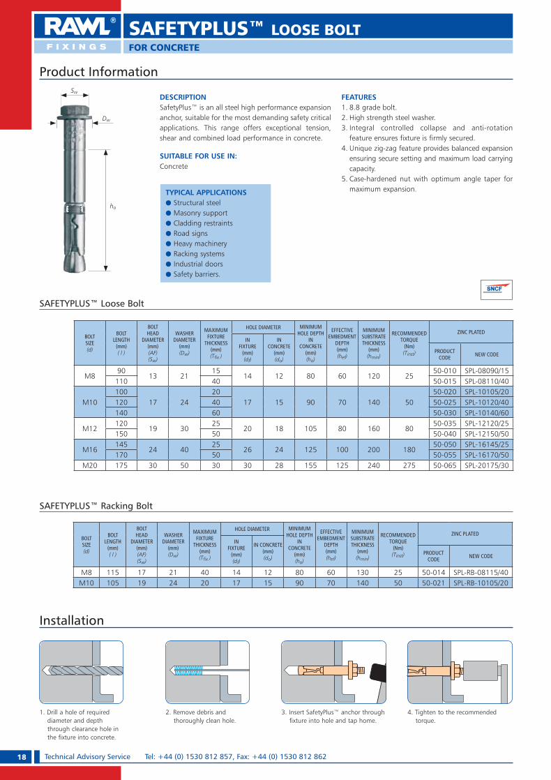
DESCRIPTIONSafetyPlus™ is an all steel high performance expansion anchor, suitable for the most demanding safety critical applications. This range offers exceptional tension, shear and combined load performance in concrete.
SUITABLE FOR USE IN:Concrete
FEATURES1. 8.8 grade bolt.2. High strength steel washer.3. Integral controlled collapse and anti-rotation
feature ensures fixture is firmly secured.4. Unique zig-zag feature provides balanced expansion
ensuring secure setting and maximum load carrying capacity.
5. Case-hardened nut with optimum angle taper for maximum expansion.
SAFETYPLUS™ Loose Bolt
Product Information
SAFETYPLUS™ LOOSE BOLTFOR CONCRETE
Installation
1. Drill a hole of required diameter and depth through clearance hole in the fixture into concrete.
2. Remove debris and thoroughly clean hole.
3. Insert SafetyPlus™ anchor through fixture into hole and tap home.
4. Tighten to the recommended torque.
BOLT SIZE(d)
BOLTLENGTH
(mm)( l )
BOLTHEAD
DIAMETER(mm)(AF)(Sw)
WASHER DIAMETER
(mm)(Dw)
MAXIMUMFIXTURE
THICKNESS(mm) (T� x )
HOLE DIAMETER MINIMUM HOLE DEPTH
IN CONCRETE
(mm)(ho)
EFFECTIVE EMBEDMENT
DEPTH(mm)(hef)
MINIMUMSUBSTRATE THICKNESS
(mm)(hmin)
RECOMMENDED TORQUE
(Nm)(Tinst)
ZINC PLATEDIN
FIXTURE(mm)(df)
IN CONCRETE
(mm)(do)
PRODUCT CODE NEW CODE
M890
13 2115
14 12 80 60 120 2550-010 SPL-08090/15
110 40 50-015 SPL-08110/40
M10100
17 2420
17 15 90 70 140 5050-020 SPL-10105/20
120 40 50-025 SPL-10120/40140 60 50-030 SPL-10140/60
M12120
19 3025
20 18 105 80 160 8050-035 SPL-12120/25
150 50 50-040 SPL-12150/50
M16145
24 4025
26 24 125 100 200 18050-050 SPL-16145/25
170 50 50-055 SPL-16170/50M20 175 30 50 30 30 28 155 125 240 275 50-065 SPL-20175/30
SAFETYPLUS™ Racking Bolt
BOLT SIZE(d)
BOLTLENGTH
(mm)( l )
BOLTHEAD
DIAMETER(mm)(AF)(Sw)
WASHER DIAMETER
(mm)(Dw)
MAXIMUMFIXTURE
THICKNESS(mm) (T� x )
HOLE DIAMETER MINIMUM HOLE DEPTH
IN CONCRETE
(mm)(ho)
EFFECTIVE EMBEDMENT
DEPTH(mm)(hef)
MINIMUMSUBSTRATE THICKNESS
(mm)(hmin)
RECOMMENDED TORQUE
(Nm)(Tinst)
ZINC PLATEDIN
FIXTURE(mm)(df)
IN CONCRETE(mm)(do)
PRODUCT CODE NEW CODE
M8 115 17 21 40 14 12 80 60 130 25 50-014 SPL-RB-08115/40M10 105 19 24 20 17 15 90 70 140 50 50-021 SPL-RB-10105/20
Dw
Sw
ho
TYPICAL APPLICATIONSe Structural steele Masonry supporte Cladding restraintse Road signse Heavy machinerye Racking systemse Industrial doorse Safety barriers.
RAWL_KATALOG_2007_2008.indb 18RAWL_KATALOG_2007_2008.indb 18 2007-10-15 14:33:412007-10-15 14:33:41
19Technical Advisory Service e-mail: [email protected] OR [email protected]
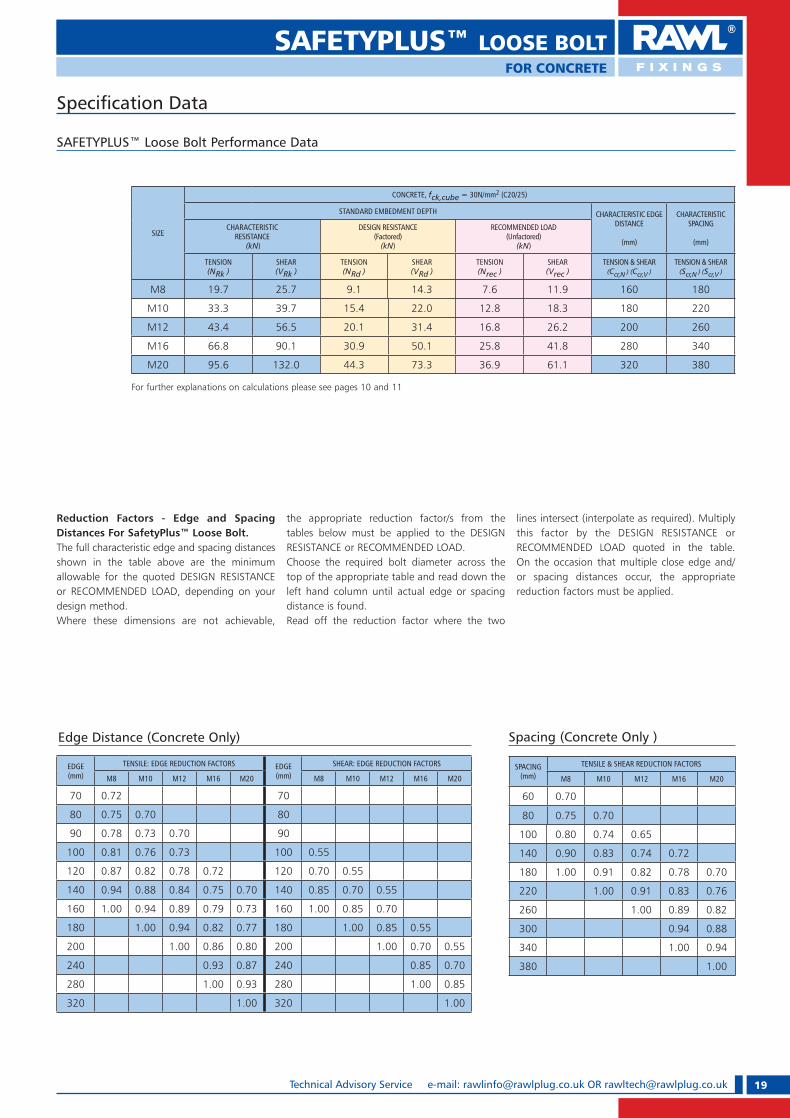
SAFETYPLUS™ LOOSE BOLTFOR CONCRETE
Speci� cation Data
SAFETYPLUS™ Loose Bolt Performance Data
SIZE
CONCRETE, fck,cube = 30N/mm2 (C20/25)
STANDARD EMBEDMENT DEPTH CHARACTERISTIC EDGE DISTANCE
(mm)
CHARACTERISTIC SPACING
(mm)
CHARACTERISTICRESISTANCE
(kN)
DESIGN RESISTANCE (Factored)
(kN)
RECOMMENDED LOAD (Unfactored)
(kN)
TENSION (NRk )
SHEAR(VRk )
TENSION (NRd )
SHEAR(VRd )
TENSION (Nrec )
SHEAR (Vrec )
TENSION & SHEAR (Ccr,N ) (Ccr,V )
TENSION & SHEAR (Scr,N ) (Scr,V )
M8 19.7 25.7 9.1 14.3 7.6 11.9 160 180
M10 33.3 39.7 15.4 22.0 12.8 18.3 180 220
M12 43.4 56.5 20.1 31.4 16.8 26.2 200 260
M16 66.8 90.1 30.9 50.1 25.8 41.8 280 340
M20 95.6 132.0 44.3 73.3 36.9 61.1 320 380
For further explanations on calculations please see pages 10 and 11
Reduction Factors - Edge and Spacing Distances For SafetyPlus™ Loose Bolt.The full characteristic edge and spacing distances shown in the table above are the minimum allowable for the quoted DESIGN RESISTANCE or RECOMMENDED LOAD, depending on your design method. Where these dimensions are not achievable,
the appropriate reduction factor/s from the tables below must be applied to the DESIGN RESISTANCE or RECOMMENDED LOAD. Choose the required bolt diameter across the top of the appropriate table and read down the left hand column until actual edge or spacing distance is found. Read off the reduction factor where the two
lines intersect (interpolate as required). Multiply this factor by the DESIGN RESISTANCE or RECOMMENDED LOAD quoted in the table. On the occasion that multiple close edge and/or spacing distances occur, the appropriate reduction factors must be applied.
Edge Distance (Concrete Only)
EDGE(mm)
TENSILE: EDGE REDUCTION FACTORS EDGE(mm)
SHEAR: EDGE REDUCTION FACTORS
M8 M10 M12 M16 M20 M8 M10 M12 M16 M20
70 0.72 70
80 0.75 0.70 80
90 0.78 0.73 0.70 90
100 0.81 0.76 0.73 100 0.55
120 0.87 0.82 0.78 0.72 120 0.70 0.55
140 0.94 0.88 0.84 0.75 0.70 140 0.85 0.70 0.55
160 1.00 0.94 0.89 0.79 0.73 160 1.00 0.85 0.70
180 1.00 0.94 0.82 0.77 180 1.00 0.85 0.55
200 1.00 0.86 0.80 200 1.00 0.70 0.55
240 0.93 0.87 240 0.85 0.70
280 1.00 0.93 280 1.00 0.85
320 1.00 320 1.00
Spacing (Concrete Only )
SPACING(mm)
TENSILE & SHEAR REDUCTION FACTORS
M8 M10 M12 M16 M20
60 0.70
80 0.75 0.70
100 0.80 0.74 0.65
140 0.90 0.83 0.74 0.72
180 1.00 0.91 0.82 0.78 0.70
220 1.00 0.91 0.83 0.76
260 1.00 0.89 0.82
300 0.94 0.88
340 1.00 0.94
380 1.00
RAWL_KATALOG_2007_2008.indb 19RAWL_KATALOG_2007_2008.indb 19 2007-10-15 14:33:502007-10-15 14:33:50

20 Technical Advisory Service Tel: +44 (0) 1530 812 857, Fax: +44 (0) 1530 812 862
DESCRIPTIONA high performance steel expansion anchor, suitable for the most demanding safety critical applications. This range offers exceptional tension, shear and com-bined load performance in concrete.
SUITABLE FOR USE IN:Concrete
FEATURES1. 8.8 grade stud with slot for final adjustment.2. High strength steel washer.3. Sleeve provides maximum shear load performance.4. Integral controlled collapse and anti-rotation
feature ensures fixture is firmly secured.5. Unique zig-zag feature provides balanced expansion
ensuring secure setting and maximum load carrying capacity.
6. Case-hardened nut with optimum angle taper for maximum expansion.
7. Nut and washer allow for fixture to be removed and relocated easily.
SAFETYPLUS™ Bolt Projecting
Product Information
Installation
1. Drill a hole of required diameter and depth through clearance hole in the fixture into concrete.
2. Remove debris and thoroughly clean hole.
3. Insert SafetyPlus™ anchor through fixture into hole and tap home.
4. Tighten to the recommended torque.
BOLT SIZE(d)
BOLTLENGTH
(mm)( l )
NUT DIAMETER
(mm)(AF)(Sw)
WASHER DIAMETER
(mm)(Dw)
MAXIMUMFIXTURE
THICKNESS(mm) (T� x )
HOLE DIAMETER MINIMUM HOLE DEPTH
IN CONCRETE
(mm)(ho)
EFFECTIVE EMBEDMENT
DEPTH(mm)(hef)
MINIMUMSUBSTRATE THICKNESS
(mm)(hmin)
RECOMMENDED TORQUE
(Nm)(Tinst)
ZINC PLATED
IN FIXTURE(mm)(df)
IN CONCRETE(mm)(do)
PRODUCT CODE NEW CODE
M8 95 13 21 15 14 12 80 60 120 25 50-110 SPL-BP-08095/15
M10 110 17 24 20 17 15 90 70 140 50 50-120 SPL-BP-10110/20
M12135
19 3025
20 18 105 80 160 8050-135 SPL-BP-12135/25
160 50 50-140 SPL-BP-12160/50
M16160
24 4025
26 24 125 100 200 18050-150 SPL-BP-16160/25
185 50 50-155 SPL-BP-16185/50
M20 190 30 50 30 30 28 155 125 240 275 50-165 SPL-BP-20190/30
Sw
Dw
ho
SAFETYPLUS™ BOLT PROJECTINGFOR CONCRETE
TYPICAL APPLICATIONSe Structural steele Masonry supporte Cladding restraintse Road signse Heavy machinerye Racking systemse Industrial doorse Safety barriers.
RAWL_KATALOG_2007_2008.indb 20RAWL_KATALOG_2007_2008.indb 20 2007-10-15 14:33:542007-10-15 14:33:54

21Technical Advisory Service e-mail: [email protected] OR [email protected]
SAFETYPLUS™ BOLT PROJECTINGFOR CONCRETE
Speci� cation Data
SAFETYPLUS™ Bolt Projecting Performance Data
Reduction Factors - Edge and Spacing Distances For SafetyPlus™ Bolt Projecting.The full characteristic edge and spacing distances shown in the table above are the minimum allowable for the quoted DESIGN RESISTANCE or RECOMMENDED LOAD, depending on your design method. Where these dimensions are not achievable,
the appropriate reduction factor/s from the tables below must be applied to the DESIGN RESISTANCE or RECOMMENDED LOAD.Choose the required bolt diameter across the top of the appropriate table and read down the left hand column until actual edge or spacing distance is found. Read off the reduction factor where the two lines intersect (interpolate as
required). Multiply this factor by the DESIGN RESISTANCE or RECOMMENDED LOAD quoted in the table. On the occasion that multiple close edge and/or spacing distances occur, the appropriate reduction factors must be applied.
Edge Distance (Concrete Only)
EDGE(mm)
TENSILE: EDGE REDUCTION FACTORS EDGE(mm)
SHEAR: EDGE REDUCTION FACTORS
M8 M10 M12 M16 M20 M8 M10 M12 M16 M20
70 0.72 70
80 0.75 0.70 80
90 0.78 0.73 0.70 90
100 0.81 0.76 0.73 100 0.55
120 0.87 0.82 0.78 0.72 120 0.70 0.55
140 0.94 0.88 0.84 0.75 0.70 140 0.85 0.70 0.55
160 1.00 0.94 0.89 0.79 0.73 160 1.00 0.85 0.70
180 1.00 0.94 0.82 0.77 180 1.00 0.85 0.55
200 1.00 0.86 0.80 200 1.00 0.70 0.55
240 0.93 0.87 240 0.85 0.70
280 1.00 0.93 280 1.00 0.85
320 1.00 320 1.00
Spacing (Concrete Only)
SPACING(mm)
TENSILE & SHEAR REDUCTION FACTORS
M8 M10 M12 M16 M20
60 0.70
80 0.75 0.70
100 0.80 0.74 0.65
140 0.90 0.83 0.74 0.72
180 1.00 0.91 0.82 0.78 0.70
220 1.00 0.91 0.83 0.76
260 1.00 0.89 0.82
300 0.94 0.88
340 1.00 0.94
380 1.00
SIZE
Concrete, fck,cube = 30N/mm2 (C20/25)
STANDARD EMBEDMENT DEPTH CHARACTERISTIC EDGE DISTANCE
(mm)
CHARACTERISTIC SPACING
(mm)CHARACTERISTIC RESISTANCE
(kN)
DESIGN RESISTANCE (Factored)
(kN)
RECOMMENDED LOAD (Unfactored)
(kN)
TENSION (NRk )
SHEAR(VRk )
TENSION (NRd )
SHEAR(VRd )
TENSION (Nrec )
SHEAR (Vrec )
TENSION & SHEAR (Ccr,N ) (Ccr,V )
TENSION & SHEAR (Scr,N ) (Scr,V )
M8 19.7 25.7 9.1 14.3 7.6 11.9 160 180
M10 33.3 39.7 15.4 22.0 12.8 18.3 180 220
M12 43.4 56.5 20.1 31.4 16.8 26.2 200 260
M16 66.8 90.1 30.9 50.1 25.8 41.8 280 340
M20 95.6 132.0 44.3 73.3 36.9 61.1 320 380
For further explanations on calculations please see pages 10 and 11
RAWL_KATALOG_2007_2008.indb 21RAWL_KATALOG_2007_2008.indb 21 2007-10-15 14:34:002007-10-15 14:34:00

22 Technical Advisory Service Tel: +44 (0) 1530 812 857, Fax: +44 (0) 1530 812 862
DESCRIPTIONA high performance steel expansion anchor, suitable for the most demanding safety critical applications. This range offers exceptional tension, shear and com-bined load performance in concrete.
SUITABLE FOR USE IN:Concrete
FEATURES1. 8.8 grade bolt.2. High strength steel washer.3. Sleeve provides maximum shear load performance.4. Integral controlled collapse and anti-rotation feature
ensures fixture is firmly secured.5. Unique zig-zag feature provides balanced expansion
ensuring secure setting and maximum load carrying capacity.
6. Case-hardened nut with optimum angle taper for maximum expansion.
SAFETYPLUS™ Limited Embedment
Product Information
Installation
1. Drill a hole of required diameter and depth through clearance hole in the fixture into concrete.
2. Remove debris and thoroughly clean hole.
3. Insert SafetyPlus™ anchor through fixture into hole and tap home.
4. Tighten to the recommended torque.
BOLT SIZE(d)
BOLTLENGTH
(mm)( l )
BOLTHEAD
DIAMETER(mm)(AF)(Sw)
WASHER DIAMETER
(mm)(Dw)
MAXIMUMFIXTURE
THICKNESS(mm) (T� x )
HOLE DIAMETER MINIMUM HOLE DEPTH
IN CONCRETE
(mm)(ho)
EFFECTIVE EMBEDMENT
DEPTH(mm)(hef)
MINIMUMSUBSTRATE THICKNESS
(mm)(hmin)
RECOMMENDED TORQUE
(Nm)(Tinst)
ZINC PLATED
IN FIXTURE(mm)(df)
IN CONCRETE(mm)(do)
PRODUCT CODE NEW CODE
M8 80 13 21 25 14 12 55 40 100 25 50-005 SPL-LE-08080/25
M10 90 17 24 25 17 15 70 50 110 50 50-018 SPL-LE-10090/25
M12 100 19 30 25 20 18 85 60 130 80 50-033 SPL-LE-12100/25
M16 130 24 40 30 26 24 100 75 165 180 50-048 SPL-LE-16130/30
Dw
Sw
ho
SAFETYPLUS™ LIMITED EMBEDMENTFOR CONCRETE
TYPICAL APPLICATIONSe Structural steel worke Road signse Industrial doorse Masonry supporte Heavy machinerye Safety barrierse Cladding restraintse Racking systems.
RAWL_KATALOG_2007_2008.indb 22RAWL_KATALOG_2007_2008.indb 22 2007-10-15 14:34:032007-10-15 14:34:03

23Technical Advisory Service e-mail: [email protected] OR [email protected]
Speci� cation Data
SAFETYPLUS™ Limited Embedment Performance Data
Reduction Factors - Edge and Spacing Distances For SafetyPlus™ Limited Embedment.The full characteristic edge and spacing distances shown in the table above are the minimum allowable for the quoted DESIGN RESISTANCE or RECOMMENDED LOAD, depending on your design method.
Where these dimensions are not achievable, the appropriate reduction factor/s from the tables below must be applied to the DESIGN RESISTANCE or RECOMMENDED LOAD.Choose the required bolt diameter across the top of the appropriate table and read down the left hand column until actual edge or spacing distance is found. Read off the reduction factor
where the two lines intersect (interpolate as required). Multiply this factor by the DESIGN RESISTANCE or RECOMMENDED LOAD quoted in the table. On the occasion that multiple close edge and/or spacing distances occur, the appropriate reduction factors must be applied.
Edge Distance (Concrete Only)
EDGE (mm)
TENSILE: EDGE REDUCTION FACTORS EDGE (mm)
SHEAR: EDGE REDUCTION FACTORS
M8 M10 M12 M16 M8 M10 M12 M16
60 0.70 60
70 0.78 0.70 70
80 0.85 0.78 0.70 80
90 0.93 0.85 0.78 90 0.75
110 1.00 0.93 0.85 0.70 110 0.84 0.70
130 1.00 0.93 0.78 130 0.92 0.80 0.73
150 1.00 0.85 150 1.00 0.90 0.82 0.80
170 0.93 170 1.00 0.91 0.87
200 1.00 200 1.00 0.93
230 230 1.00
Spacing (Concrete Only)
SPACING(mm)
TENSILE & SHEAR REDUCTION FACTORS
M8 M10 M12 M16
120 0.70
140 0.80 0.74
160 0.90 0.83 0.74
180 1.00 0.91 0.82 0.83
200 1.00 0.91 0.88
220 1.00 0.94
240 1.00
SAFETYPLUS™ LIMITED EMBEDMENTFOR CONCRETE
SIZE
Concrete, fck,cube = 30N/mm2 (C20/25)
STANDARD EMBEDMENT DEPTH CHARACTERISTIC EDGE DISTANCE
(mm)
CHARACTERISTIC SPACING
(mm)CHARACTERISTIC RESISTANCE
(kN)DESIGN RESISTANCE (Factored)
(kN)RECOMMENDED LOAD (Unfactored)
(kN)
TENSION (NRk )
SHEAR(VRk )
TENSION (NRd )
SHEAR(VRd )
TENSION (Nrec )
SHEAR (Vrec )
TENSION(Ccr,N )
SHEAR(Ccr,V )
TENSION & SHEAR (Scr,N ) (Scr ,V)
M8 12.0 18.9 5.6 10.5 4.7 8.8 110 150 180
M10 18.9 29.5 8.7 16.5 7.3 13.8 130 170 200
M12 26.2 44.0 12.1 24.5 10.1 20.4 150 200 220
M16 47.0 77.2 21.7 42.9 18.1 35.8 200 230 240
For further explanations on calculations please see pages 10 and 11
RAWL_KATALOG_2007_2008.indb 23RAWL_KATALOG_2007_2008.indb 23 2007-10-15 14:34:082007-10-15 14:34:08
24 Technical Advisory Service Tel: +44 (0) 1530 812 857, Fax: +44 (0) 1530 812 862
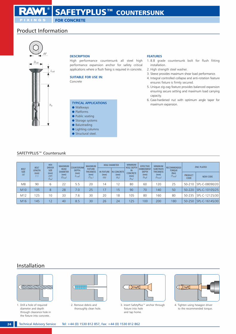
DESCRIPTIONHigh performance countersunk all steel high performance expansion anchor for safety critical applications where a flush fixing is required in concrete.
SUITABLE FOR USE IN:Concrete
FEATURES1. 8.8 grade countersunk bolt for flush fitting
installation.2. High strength steel washer.3. Sleeve provides maximum shear load performance.4. Integral controlled collapse and anti-rotation feature
ensures fixture is firmly secured.5. Unique zig-zag feature provides balanced expansion
ensuring secure setting and maximum load carrying capacity.
6. Case-hardened nut with optimum angle taper for maximum expansion.
SAFETYPLUS™ Countersunk
Product Information
Installation
1. Drill a hole of required diameter and depth through clearance hole in the fixture into concrete..
2. Remove debris and thoroughly clean hole.
3. Insert SafetyPlus™ anchor through fixture into hole and tap home.
4. Tighten using hexagon driver to the recommended torque.
BOLT SIZE(d)
BOLTLENGTH
(mm)( l )
HEXDRIVER
SIZE(mm)(AF)(Sw)
MAXIMUMHEAD
DIAMETER(mm)(Dcsk)
COUNTERSINK DEPTH.(mm)(Lcsk)
MAXIMUMFIXTURE
THICKNESS(mm) (T� x )
HOLE DIAMETER MINIMUM HOLE DEPTH
IN CONCRETE
(mm)(ho)
EFFECTIVE EMBEDMENT
DEPTH(mm)(hef)
MINIMUMSUBSTRATE THICKNESS
(mm)(hmin)
RECOMMENDED TORQUE
(Nm)(Tinst)
ZINC PLATED
IN FIXTURE(mm)(df)
IN CONCRETE(mm)(do)
PRODUCT CODE NEW CODE
M8 90 6 22 5.5 20 14 12 80 60 120 25 50-210 SPL-C-08090/20
M10 105 8 28 7.0 25 17 15 90 70 140 50 50-220 SPL-C-10105/25
M12 125 10 33 7.6 30 20 18 105 80 160 80 50-235 SPL-C-12125/30
M16 145 12 40 8.5 30 26 24 125 100 200 180 50-250 SPL-C-16145/30
Dcsk
ho
AF
SAFETYPLUS™ COUNTERSUNKFOR CONCRETE
Lcsk
TYPICAL APPLICATIONSe Walkwayse Platformse Public seatinge Storage systemse Balustradinge Lighting columnse Structural steel.
RAWL_KATALOG_2007_2008.indb 24RAWL_KATALOG_2007_2008.indb 24 2007-10-15 14:34:132007-10-15 14:34:13

25Technical Advisory Service e-mail: [email protected] OR [email protected]
SAFETYPLUS™ COUNTERSUNKFOR CONCRETE
SAFETYPLUS™ Countersunk Performance Data
SIZE
CONCRETE, fck,cube = 30N/mm2 (C20/25)
STANDARD EMBEDMENT DEPTH CHARACTERISTIC EDGE DISTANCE
(mm)
CHARACTERISTIC SPACING
(mm)CHARACTERISTIC RESISTANCE
(kN)DESIGN RESISTANCE (Factored)
(kN)RECOMMENDED LOAD (Unfactored)
(kN)
TENSION (NRk )
SHEAR(VRk )
TENSION (NRd )
SHEAR(VRd )
TENSION (Nrec )
SHEAR (Vrec )
TENSION & SHEAR (Ccr,N ) (Ccr,V )
TENSION & SHEAR (Scr,N ) (Scr ,V)
M8 19.7 25.7 9.1 14.3 7.6 11.9 160 180
M10 33.3 39.7 15.4 22.0 12.8 18.3 180 220
M12 43.4 56.5 20.1 31.4 16.8 26.2 200 260
M16 66.8 90.1 30.9 50.1 25.8 41.8 280 340
For further explanations on calculations please see pages 10 and 11
Reduction Factors - Edge and Spacing Distances For SafetyPlus™ Countersunk.The full characteristic edge and spacing distances shown in the table above are the minimum allowable for the quoted DESIGN RESISTANCE or RECOMMENDED LOAD, depending on your design method. Where these dimensions are not achievable,
the appropriate reduction factor/s from the tables below must be applied to the DESIGN RESISTANCE or RECOMMENDED LOAD.Choose the required bolt diameter across the top of the appropriate table and read down the left hand column until actual edge or spacing distance is found. Read off the reduction factor where the two lines intersect (interpolate as
required). Multiply this factor by the DESIGN RESISTANCE or RECOMMENDED LOAD quoted in the table. On the occasion that multiple close edge and/or spacing distances occur, the appropriate reduction factors must be applied.
Edge Distance (Concrete Only)
EDGE (mm)
TENSILE: EDGE REDUCTION FACTORS EDGE (mm)
SHEAR: EDGE REDUCTION FACTORS
M8 M10 M12 M16 M8 M10 M12 M16
70 0.72 70
80 0.75 0.70 80
90 0.78 0.73 0.70 90
100 0.81 0.76 0.73 100 0.55
120 0.87 0.82 0.78 0.72 120 0.70 0.55
140 0.94 0.88 0.84 0.75 140 0.85 0.70 0.55
160 1.00 0.94 0.89 0.79 160 1.00 0.85 0.70
180 1.00 0.94 0.82 180 1.00 0.85 0.55
200 1.00 0.86 200 1.00 0.70
240 0.93 240 0.85
280 1.00 280 1.00
Spacing (Concrete Only)
SPACING(mm)
TENSILE & SHEAR REDUCTION FACTORS
M8 M10 M12 M16
60 0.70
80 0.75 0.70
100 0.80 0.74 0.65
140 0.90 0.83 0.74 0.72
180 1.00 0.91 0.82 0.78
220 1.00 0.91 0.83
260 1.00 0.89
300 0.94
340 1.00
Speci� cation Data
RAWL_KATALOG_2007_2008.indb 25RAWL_KATALOG_2007_2008.indb 25 2007-10-15 14:34:192007-10-15 14:34:19

26 Technical Advisory Service Tel: +44 (0) 1530 812 857, Fax: +44 (0) 1530 812 862
SOCKET ANCHORFOR CONCRETE
DESCRIPTIONA versatile problem-solving fixing, providing a permanent high performance threaded socket for a wide variety of studding applications, including deep embedment applications.
SUITABLE FOR USE IN:Concrete
FEATURES1. Internally threaded socket for stud or rebar.2. Integral controlled collapse and anti-rotation
feature ensures fixture is firmly secured.3. Unique zig-zag feature provides balanced
expansion ensuring secure setting and maximum load carrying capacity.
4. Case-hardened nut with optimum angle taper for maximum expansion.
Product Information
SOCKET ANCHOR
THREAD SIZE(d)
ANCHORLENGTH
(mm)( l )
INTERNAL THREAD LENGTH
(mm)(lg )
HOLE DIAMETER SET FLUSH TO SURFACE SET AT DEPTH MAX. RECOMMENDED TORQUE (Nm) ZINC PLATED
INFIXTURE
(mm)(df )
INCONCRETE
(mm)(do )
MINIMUM HOLE
DEPTH(mm)(df )
EFFECTIVE EMBEDMENT
DEPTH(mm)(hef )
MINIMUMSUBSTRATE THICKNESS
(mm)(hmin )
MINIMUM HOLE
DEPTH(mm)(df )
EFFECTIVE EMBEDMENT
DEPTH(mm)(hef )
MINIMUMSUBSTRATE THICKNESS
(mm)(hmin )
4.6 STUD(Tinst )
8.8 STUD(Tinst )
PRODUCTCODE NEW CODE
M8 55 8 10 12 65 45 90 80 60 120 11 19 86-510 SOC-08
M10 67 13 12 15 75 55 110 90 70 140 22 37 86-515 SOC-10
M12 80 17 14 18 90 65 130 105 80 160 39 65 86-520 SOC-12
M16 95 18 18 24 105 80 160 125 100 200 96 163 86-525 SOC-16
M20 115 24 24 28 125 95 190 155 125 250 187 280 86-530 SOC-20
Installation
1. Screw studding into socket. Assemble two nuts at the other end of the studding.
2. Ensuring nuts are securely locked together, apply the recommended torque through the top nut. Carefully slacken and remove nuts.
3. Apply fixture, washer and hexagon nut. 4. Apply torque to ensure clamping of fixture against concrete surface.
ho
lg
TYPICAL APPLICATIONSe Starter bare Formwork supportse Temporary workse Heavy machinerye Lighting columnse Structural steelworks.
RAWL_KATALOG_2007_2008.indb 26RAWL_KATALOG_2007_2008.indb 26 2007-10-15 14:34:212007-10-15 14:34:21

27Technical Advisory Service e-mail: [email protected] OR [email protected]
SOCKET ANCHORFOR CONCRETE
SOCKET ANCHOR Performance Data
Reduction Factors - Edge and Spacing Distances for Socket Anchor.The full characteristic edge and spacing distances shown in the table above are the minimum allowable for the quoted DESIGN RESISTANCE or RECOMMENDED LOAD, depending on your design method. Where these dimensions are not achievable,
the appropriate reduction factor/s from the tables below must be applied to the DESIGN RESISTANCE or RECOMMENDED LOAD.Choose the required bolt diameter across the top of the appropriate table and read down the left hand column until actual edge or spacing distance is found. Read off the reduction factor where the two lines intersect (interpolate as
required). Multiply this factor by the DESIGN RESISTANCE or RECOMMENDED LOAD quoted in the table. On the occasion that multiple close edge and/or spacing distances occur, the appropriate reduction factors must be applied
Edge Distance (Concrete Only)
EDGE (mm)
TENSILE: EDGE REDUCTION FACTORS
M8 M10 M12 M16 M20
70 0.7280 0.75 0.7090 0.78 0.73 0.70100 0.81 0.76 0.73120 0.87 0.82 0.78 0.72140 0.94 0.88 0.84 0.75 0.70160 1.00 0.94 0.89 0.79 0.73180 1.00 0.94 0.82 0.77200 1.00 0.86 0.80240 0.93 0.87280 1.00 0.93320 1.00
Speci� cation Data
SIZE
CONCRETE, fck,cube = 30N/mm2 (C20/25)
ANCHOR SET FLUSH TO THE SURFACE* ANCHOR SET FLUSH AT DEPTH**CHARACTERISTIC EDGE DISTANCE
(mm)
CHARACTERISTIC SPACING
(mm)CHARACTERISTIC
RESISTANCE(kN)
DESIGN RESISTANCE (Factored)
(kN)
RECOMMENDED LOAD (Unfactored)
(kN)
CHARACTERISTIC RESISTANCE
(kN)
DESIGN RESISTANCE (Factored)
(kN)
RECOMMENDED LOAD (Unfactored)
(kN)
TENSION (NRk )
TENSION (NRd )
TENSION (Nrec )
TENSION (NRk )
TENSION (NRd )
TENSION(Nrec )
TENSION(Ccr,N )
TENSION (Scr,N )
M8 11.9 5.5 4.6 19.7 9.1 7.6 160 180M10 18.9 8.8 7.3 33.3 15.4 12.8 180 220M12 26.4 12.2 10.2 43.4 20.1 16.8 200 260M16 46.5 21.6 18.0 66.8 30.9 25.8 280 340M20 66.6 30.8 25.7 95.6 44.3 36.9 320 380
* NOTE: Grade of stud 4.6For further explanations on calculations please see pages 10 and 11
** NOTE: Grade of stud 8.8
SIZE
CONCRETE, fck,cube = 60N/mm2 (C50/60)
ANCHOR SET FLUSH TO THE SURFACE* ANCHOR SET FLUSH AT DEPTH**CHARACTERISTIC EDGE DISTANCE
(mm)
CHARACTERISTIC SPACING
(mm)CHARACTERISTIC
RESISTANCE(kN)
DESIGN RESISTANCE (Factored)
(kN)
RECOMMENDED LOAD (Unfactored)
(kN)
CHARACTERISTIC RESISTANCE
(kN)
DESIGN RESISTANCE (Factored)
(kN)
RECOMMENDED LOAD (Unfactored)
(kN)
TENSION (NRk )
TENSION (NRd )
TENSION (Nrec )
TENSION (NRk )
TENSION (NRd )
TENSION (Nrec )
TENSION (Ccr,N )
TENSION (Scr,N )
M8 12.2 5.6 4.7 25.7 11.9 9.9 160 180M10 19.2 8.9 7.4 43.2 20.0 16.7 180 220M12 28.0 13.0 10.8 56.0 25.9 21.6 200 260M16 52.3 24.2 20.2 87.4 40.5 33.8 280 340M20 81.3 37.6 31.3 124.4 57.6 48.0 320 380
* NOTE: Grade of stud 4.6For further explanations on calculations please see pages 10 and 11
** NOTE: Grade of stud 8.8
Spacing (Concrete Only)
SPACING(mm)
TENSILE & SHEAR REDUCTION FACTORS
M8 M10 M12 M16 M20
60 0.7080 0.75 0.70100 0.80 0.74 0.65140 0.90 0.83 0.74 0.72180 1.00 0.91 0.82 0.78 0.70220 1.00 0.91 0.83 0.76260 1.00 0.89 0.82300 0.94 0.88340 1.00 0.94380 1.00
RAWL_KATALOG_2007_2008.indb 27RAWL_KATALOG_2007_2008.indb 27 2007-10-15 14:34:222007-10-15 14:34:22
28 Technical Advisory Service Tel: +44 (0) 1530 812 857, Fax: +44 (0) 1530 812 862
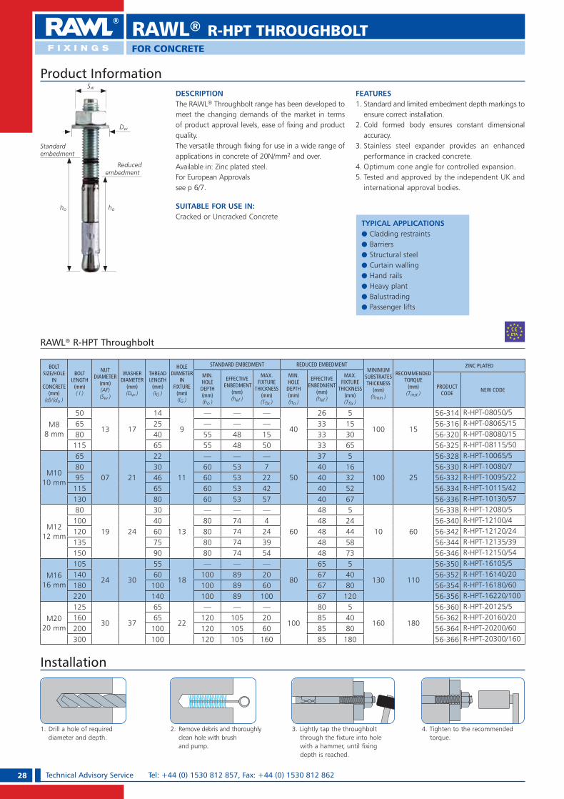
DESCRIPTIONThe RAWL® Throughbolt range has been developed to meet the changing demands of the market in terms of product approval levels, ease of fixing and product quality.The versatile through fixing for use in a wide range of applications in concrete of 20N/mm2 and over.Available in: Zinc plated steel.For European Approvals see p 6/7.
SUITABLE FOR USE IN:Cracked or Uncracked Concrete
FEATURES1. Standard and limited embedment depth markings to
ensure correct installation.2. Cold formed body ensures constant dimensional
accuracy.3. Stainless steel expander provides an enhanced
performance in cracked concrete.4. Optimum cone angle for controlled expansion.5. Tested and approved by the independent UK and
international approval bodies.
Product Information
RAWL® R-HPT Throughbolt
Installation
1. Drill a hole of required diameter and depth.
2. Remove debris and thoroughly clean hole with brush and pump.
3. Lightly tap the throughbolt through the fixture into hole with a hammer, until fixing depth is reached.
4. Tighten to the recommended torque.
ho
Dw
Sw
Standardembedment
Reducedembedment
ho
RAWL® R-HPT THROUGHBOLTFOR CONCRETE
BOLTSIZE/HOLE
IN CONCRETE
(mm)(d)/(do )
BOLTLENGTH
(mm)( l )
NUT DIAMETER
(mm)(AF)(Sw )
WASHER DIAMETER
(mm)(Dw )
THREADLENGTH
(mm)(lG )
HOLEDIAMETER
IN FIXTURE
(mm)(lG )
STANDARD EMBEDMENT REDUCED EMBEDMENTMINIMUM
SUBSTRATES THICKNESS
(mm)(hmin )
RECOMMENDEDTORQUE
(mm)(Tinst )
ZINC PLATED
MIN.HOLE
DEPTH(mm)(ho )
EFFECTIVE ENBEDMENT
(mm)(hef )
MAX.FIXTURE
THICKNESS(mm)(T� x )
MIN.HOLE
DEPTH(mm)(ho )
EFFECTIVEENBEDMENT
(mm)(hef )
MAX.FIXTURE
THICKNESS(mm)(T� x )
PRODUCT CODE NEW CODE
M88 mm
50
13 17
14
9
— — —
40
26 5
100 15
56-314 R-HPT-08050/565 25 — — — 33 15 56-316 R-HPT-08065/1580 40 55 48 15 33 30 56-320 R-HPT-08080/15115 65 55 48 50 33 65 56-325 R-HPT-08115/50
M1010 mm
65
07 21
22
11
— — —
50
37 5
100 25
56-328 R-HPT-10065/580 30 60 53 7 40 16 56-330 R-HPT-10080/795 46 60 53 22 40 32 56-332 R-HPT-10095/22115 65 60 53 42 40 52 56-334 R-HPT-10115/42130 80 60 53 57 40 67 56-336 R-HPT-10130/57
M1212 mm
80
19 24
30
13
— — —
60
48 5
10 60
56-338 R-HPT-12080/5100 40 80 74 4 48 24 56-340 R-HPT-12100/4120 60 80 74 24 48 44 56-342 R-HPT-12120/24135 75 80 74 39 48 58 56-344 R-HPT-12135/39150 90 80 74 54 48 73 56-346 R-HPT-12150/54
M1616 mm
105
24 30
55
18
— — —
80
65 5
130 110
56-350 R-HPT-16105/5140 60 100 89 20 67 40 56-352 R-HPT-16140/20180 100 100 89 60 67 80 56-354 R-HPT-16180/60220 140 100 89 100 67 120 56-356 R-HPT-16220/100
M2020 mm
125
30 37
65
22
— — —
100
80 5
160 180
56-360 R-HPT-20125/5160 65 120 105 20 85 40 56-362 R-HPT-20160/20200 100 120 105 60 85 80 56-364 R-HPT-20200/60300 100 120 105 160 85 180 56-366 R-HPT-20300/160
TYPICAL APPLICATIONSe Cladding restraintse Barriers e Structural steele Curtain wallinge Hand railse Heavy plante Balustradinge Passenger lifts
RAWL_KATALOG_2007_2008.indb 28RAWL_KATALOG_2007_2008.indb 28 2007-10-15 14:34:242007-10-15 14:34:24

29Technical Advisory Service e-mail: [email protected] OR [email protected]
RAWL® R-HPT THROUGHBOLTFOR CONCRETE
Speci� cation Data
RAWL® R-HPT Throughbolt Projecting Performance Data
Reduction Factors - Edge and Spacing Distances for Rawl® R-HPT.The full characteristic edge and spacing distances shown in the table above are the minimum allowable for the quoted DESIGN RESISTANCE or RECOMMENDED LOAD, depending on your design method. Where these dimensions are not achievable,
the appropriate reduction factor/s from the tables below must be applied to the DESIGN RESISTANCE or RECOMMENDED LOAD.Choose the required bolt diameter across the top of the appropriate table and read down the left hand column until actual edge or spacing distance is found. Read off the reduction factor where the two lines intersect (interpolate as
required). Multiply this factor by the DESIGN RESISTANCE or RECOMMENDED LOAD quoted in the table. On the occasion that multiple close edge and/or spacing distances occur, the appropriate reduction factors must be applied.
Edge Distance (Concrete Only) Spacing (Concrete Only)
For further explanations on calculations please see pages 10 and 11
SIZE
CONCRETE, fck,cube = 30N/mm2 (C20/25)
STANDARD EMBEDMENT DEPTH REDUCED EMBEDMENT DEPTH CHARACTERISTIC EDGE
DISTANCE (mm)
CHARACTERISTIC SPACING
(mm)CHARACTERISTIC
LOAD (kN)
DESIGN LOAD (kN)
RECOMMENDED LOAD (kN)
CHARACTERISTIC LOAD (kN)
DESIGN LOAD (kN)
RECOMMENDED LOAD (kN)
TENSION (NRk )
SHEAR(VRk )
TENSION (NRd )
SHEAR(VRd )
TENSION (Nrec )
SHEAR (Vrec )
TENSION (NRk )
SHEAR(VRk )
TENSION (NRd )
SHEAR(VRd )
TENSION (Nrec )
SHEAR (Vrec )
TENSION(Ccr,N )
SHEAR(Ccr,V )
TENSION & SHEAR (Scr,N ) (Scr,V )
M8 11.1 16.8 5.1 9.3 4.3 7.8 9.2 9.6 4.3 5.3 3.6 4.4 80 80 100
M10 17.5 19.3 8.1 10.7 6.8 8.9 11.1 15.3 5.2 8.5 4.3 7.1 100 100 120
M12 26.3 32.2 12.2 17.9 10.2 14.9 17.2 23.3 8.0 12.9 6.7 10.8 120 120 150
M16 42.6 48.8 19.7 27.1 16.4 22.6 25.6 44.0 11.9 24.2 9.9 20.2 160 160 180
M20 60.3 75.9 27.9 42.1 23.3 35.1 47.1 65.6 21.8 36.5 18.2 30.4 190 190 260
EDGE (mm)TENSILE: EDGE REDUCTION FACTORS SHEAR: EDGE REDUCTION FACTORS
M8 M10 M12 M16 M20 M8 M10 M12 M16 M20
40 0.60
50 0.73 0.62
60 0.87 0.65 0.74 0.60
80 1.00 0.83 0.65 1.00 0.80 0.67
100 1.00 0.83 0.65 1.00 0.84 0.62
120 1.00 0.77 0.65 1.00 0.74 0.58
140 0.88 0.77 0.87 0.73
160 1.00 0.88 1.00 0.82
190 1.00 1.00
SPACING(mm)
TENSILE & SHEAR REDUCTION FACTORS
M8 M10 M12 M16 M20
40
50 0.65
60 0.77 0.65
80 0.88 0.77 0.65
100 1.00 0.88 0.77 0.65
120 1.00 0.88 0.77
150 1.00 0.88 0.74
180 1.00 0.83
220 0.91
260 1.00
SIZE
CONCRETE, fck,cube = 30N/mm2 (C20/25)
STANDARD EMBEDMENT DEPTH REDUCED EMBEDMENT DEPTH CHARACTERISTIC EDGE
DISTANCE (mm)
CHARACTERISTIC SPACING
(mm)CHARACTERISTIC
LOAD(kN)
DESIGN LOAD (kN)
RECOMMENDED LOAD (kN)
CHARACTERISTIC LOAD (kN)
DESIGN LOAD (kN)
RECOMMENDED LOAD (kN)
TENSION (NRk )
SHEAR(VRk )
TENSION (NRd )
SHEAR(VRd )
TENSION (Nrec )
SHEAR (Vrec )
TENSION (NRk )
SHEAR(VRk )
TENSION (NRd )
SHEAR(VRd )
TENSION (Nrec )
SHEAR (Vrec )
TENSION(Ccr,N )
SHEAR(Ccr,V )
TENSION & SHEAR (Scr,N ) (Scr,V )
M8 6.7 15.1 3.1 8.4 2.6 7.0 5.5 8.6 2.6 4.8 2.2 4.0 80 80 100
M10 10.9 17.6 5.0 9.7 4.2 8.1 6.9 13.9 3.2 7.7 2.7 6.4 100 100 120
M12 16.8 29.6 7.8 16.5 6.5 13.7 11.0 21.4 5.1 11.9 4.3 9.9 120 120 150
M16 28.1 45.4 13.0 25.2 10.8 21.0 16.9 40.9 7.9 22.5 6.5 18.8 160 160 180
M20 41.0 71.3 19.0 39.6 15.8 33.0 32.0 61.7 14.8 34.3 12.4 28.6 190 190 260
Non-Cracked Concrete Performance Data
Cracked Concrete Performance Data
RAWL_KATALOG_2007_2008.indb 29RAWL_KATALOG_2007_2008.indb 29 2007-10-15 14:34:272007-10-15 14:34:27
30 Technical Advisory Service Tel: +44 (0) 1530 812 857, Fax: +44 (0) 1530 812 862
RAWL® R-SPT THROUGHBOLTFOR CONCRETE
SUITABLE FOR USE IN:Concrete
FEATURES1. Embedment depth markings
to ensure correct installation.2. Cold formed body ensures
constant dimensional accuracy.3. Optimum cone angle
for controlled expansion.4. Tested and approved by
the independent UK and international approval bodies.
DESCRIPTIONThe RAWL® Throughbolt range has been developed to meet the changing demands of the market in terms of product approval levels, ease of fixing and product quality.The versatile through fixing for use in a wide range of applications in concrete of 20N/mm2 and over.Available in: Zinc plated steel, Hot dip galvanized, Stainless steel grade A4.For European Approvals see p. 6/7
Product Information
ho
Dw
Sw
Standardembedment
Reducedembedment
ho
RAWL® R-SPT Throughbolt - Zinc Plated
BOLTSIZE(d)
HOLE IN
CONCRETE(mm)(do )
BOLTLENGTH
(mm)( l )
NUT DIAMETER
(mm)(AF)(Sw )
WASHER DIAMETER
(mm)(Dw )
THREADLENGTH
(mm)(lG )
HOLEDIAMETERIN FIXTURE
(mm)(lG )
STANDARD EMBEDMENT REDUCED EMBEDMENTMINIMUM SUBSTRATE THIC KNESS
(mm)(hmin )
REC.TORQUE
(mm)(Tinst )
ZINC PLATED
MINIMUM HOLE DEPTH(mm)(ho )
EFFECTIVEEMBEDMENT
(mm)(hef )
MAXIMUMFIXTURE
THICKNESS(mm)(T� x )
MINIMUM HOLE
DEPTH(mm)(ho )
EFFECTIVEEMBEDMENT
(mm)(hef )
MAXIMUMFIXTURE
THICKNESS(mm)(T� x )
PRODUCT CODE NEW CODE
M6 6
40
10 12.5
15
6.5
— — — 24 16 7
100 5
56-102 R-SPT-06040/755 25 — — — 30 22 16 56-104 R-SPT-06055/1670 35 50 42 12 30 22 32 56-108 R-SPT-06070/1285 50 50 42 26 30 22 46 56-110 R-SPT-06085/2695 60 50 42 36 30 22 56 56-112 R-SPT-06095/36
M8 8
50
13 17
14
9
— — — 40 26 5
100 15
56-114 R-SPT-08050/565 25 — — — 40 33 15 56-116 R-SPT-08065/1580 40 55 48 15 40 33 30 56-120 R-SPT-08080/1595 55 55 48 30 40 33 45 56-122 R-SPT-08095/30115 75 55 48 50 40 33 65 56-125 R-SPT-08115/50150 70 55 48 85 40 33 100 56-123 R-SPT-08115/85
M10 10
65
17 21
21
11
— — — 50 37 5
100 25
56-129 R-SPT-10065/580 30 60 52 7 50 40 16 56-128 R-SPT-10080/795 45 60 52 22 50 40 32 56-132 R-SPT-10095/22115 65 60 52 42 50 40 52 56-136 R-SPT-10115/42130 80 60 52 57 50 40 67 56-138 R-SPT-10130/57150 100 60 52 77 50 40 87 56-137 R-SPT-10150/77
M12 12
80
19 24
30
13
— — — 60 48 5
110 45
56-139 R-SPT-12080/5100 40 80 69 4 60 48 24 56-140 R-SPT-12100/4120 60 80 69 24 60 48 44 56-144 R-SPT-12120/24135 75 80 69 39 60 48 58 56-148 R-SPT-12135/39150 90 80 69 54 60 48 73 56-150 R-SPT-12150/54180 100 80 69 84 60 48 103 56-147 R-SPT-12180/84220 120 80 69 124 60 48 143 56-149 R-SPT-12220/124235 140 80 69 139 60 48 158 56-146 R-SPT-12235/139
M16 16
90
24 30
32
18
— — — 50 37 20
130 110
56-154 R-SPT-16090/20105 55 — — — 80 67 5 56-153 R-SPT-16105/25125 45 100 89 5 80 67 25 56-155 R-SPT-16125/5140 60 100 89 20 80 67 40 56-152 R-SPT-16140/20150 70 100 89 30 80 67 50 56-163 R-SPT-16150/30180 100 100 89 60 80 67 80 56-156 R-SPT-16180/60220 140 100 89 100 80 67 120 56-158 R-SPT-16220/100280 140 100 89 160 80 67 180 56-157 R-SPT-16280/160
M20 20
125
30 37
65
22
— — — 100 85 5
160 180
56-159 R-SPT-20125/5160 65 120 105 20 100 85 40 56-160 R-SPT-20160/20200 100 120 105 60 100 85 80 56-164 R-SPT-20200/60300 100 120 105 160 100 85 180 56-166 R-SPT-20300/160
M24 24180
36 4465
26135 112 20 120 92 35
200 32056-168 R-SPT-24180/20
260 65 135 112 100 120 92 115 56-172 R-SPT-24260/100300 105 135 112 140 120 92 155 56-175 R-SPT-24300/140
TYPICAL APPLICATIONSe Cladding restrainte Curtain walle Balustradinge Barrierse Handrailse Rackinge Structural Steele Bollards.
RAWL_KATALOG_2007_2008.indb 30RAWL_KATALOG_2007_2008.indb 30 2007-10-15 14:34:292007-10-15 14:34:29

31Technical Advisory Service e-mail: [email protected] OR [email protected]
RAWL® R-SPT THROUGHBOLTFOR CONCRETE
RAWL® R-SPT Throughbolt - Hot Dip Galvanized
BOLTSIZE(d)
HOLE IN
CONCRETE(mm)(do )
BOLTLENGTH
(mm)( l )
NUT DIAMETER
(mm)(AF)(Sw )
WASHER DIAMETER
(mm)(Dw )
THREADLENGTH
(mm)(lG )
HOLEDIAMETERIN FIXTURE
(mm)(lG )
STANDARD EMBEDMENT REDUCED EMBEDMENTMINIMUM SUBSTRATE THICKNESS
(mm)(hmin )
REC.TORQUE
(mm)(Tinst )
HOT DIP GALVANIZED
MINIMUM HOLE DEPTH(mm)(ho )
EFFECTIVEEMBEDMENT
(mm)(hef )
MAXIMUMFIXTURE
THICKNESS(mm)(T� x )
MINIMUM HOLE
DEPTH(mm)(ho )
EFFECTIVEEMBEDMENT
(mm)(hef )
MAXIMUMFIXTURE
THICKNESS(mm)(T� x )
PRODUCT CODE NEW CODE
M8 8
50
13 17
14
9
— — — 40 26 5
100 15
56-814 R-SPT-HD-08050/5
65 25 — — — 40 33 15 56-816 R-SPT-HD-08065/15
80 40 55 48 15 40 33 30 56-820 R-SPT-HD-08080/15
95 55 55 48 30 40 33 45 56-822 R-SPT-HD-08095/30
115 75 55 48 50 40 33 65 56-825 SPT-HD-08115/50
M10 10
65
17 21
21
11
— — — 50 37 5
100 25
56-829 R-SPT-HD-10065/5
80 30 60 52 7 50 39 16 56-828 R-SPT-HD-10080/7
95 45 60 52 22 50 40 32 56-832 R-SPT-HD-10095/22
115 65 60 52 42 50 40 52 56-836 R-SPT-HD-10115/42
130 80 60 52 57 50 40 67 56-838 R-SPT-HD-10130/57
M12 12
80
19 24
30
13
— — — 60 48 5
110 45
56-839 R-SPT-HD-12080/5
100 40 80 69 4 60 48 24 56-840 R-SPT-HD-12100/4
120 60 80 69 24 60 48 44 56-844 R-SPT-HD-12120/24
135 75 80 69 39 60 48 58 56-848 R-SPT-HD-12135/39
150 90 80 69 54 60 48 75 56-850 R-SPT-HD-12150/54
180 100 80 69 84 60 48 105 56-847 R-SPT-HD-12180/84
M16 16
105
24 30
55
18
— — — 80 65 5
130 110
56-853 R-SPT-HD-16105/25
140 60 100 89 20 80 67 40 56-852 R-SPT-HD-16140/20
180 100 100 89 60 80 67 80 56-856 R-SPT-HD-16180/60
220 140 100 89 100 80 67 120 56-858 R-SPT-HD-16220/100
M20 20
125
30 37
65
22
— — — 100 80 5
160 180
56-859 R-SPT-HD-20125/5
160 65 120 105 20 100 85 40 56-860 R-SPT-HD-20160/20
200 100 120 105 60 100 85 80 56-864 R-SPT-HD-20200/60
M24 24 260 36 44 65 26 135 112 100 120 92 115 200 320 56-872 R-SPT-HD-24260/100
Product Information
RAWL® R-SPT Throughbolt - Stainless Steel Grade 316 (A4)
BOLTSIZE(d)
HOLE IN
CONCRETE(mm)(do )
BOLTLENGTH
(mm)( l )
NUT DIAMETER
(mm)(AF)(Sw )
WASHER DIAMETER
(mm)(Dw )
THREADLENGTH
(mm)(lG )
HOLEDIAMETERIN FIXTURE
(mm)(lG )
STANDARD EMBEDMENT REDUCED EMBEDMENTMINIMUM SUBSTRATE THICKNESS
(mm)(hmin )
REC.TORQUE
(mm)(Tinst )
STAINLESS STEEL GRADE 316 (A4)
MINIMUM HOLE DEPTH(mm)(ho )
EFFECTIVEEMBEDMENT
(mm)(hef )
MAXIMUMFIXTURE
THICKNESS(mm)(T� x )
MINIMUM HOLE
DEPTH(mm)(ho )
EFFECTIVEEMBEDMENT
(mm)(hef )
MAXIMUMFIXTURE
THICKNESS(mm)(T� x )
PRODUCT CODE NEW CODE
M6 655
10 12.525
6.5— — — 30 22 16
100 556-604 R-SPT-A4-06055/16
85 50 50 42 26 30 22 46 56-610 R-SPT-A4-06085/26
M8 8
50
13 17
14
9
— — — 40 26 5
100 15
56-614 R-SPT-A4-08050/5
65 25 — — — 40 33 15 56-616 R-SPT-A4-08065/15
80 40 55 48 15 40 33 30 56-620 R-SPT-A4-08080/15
105 25 55 48 40 40 33 55 56-624 R-SPT-A4-080105/40
M10 10
65
17 21
21
11
— — — 50 37 5
100 25
56-627 R-SPT-A4-10065/5
80 30 60 52 7 50 39 16 56-628 R-SPT-A4-10080/7
95 45 60 52 22 50 40 32 56-632 R-SPT-A4-10095/22
115 65 60 52 42 50 40 52 56-636 R-SPT-A4-10115/42
130 80 60 52 57 50 40 67 56-638 R-SPT-A4-10130/57
M12 12
100
19 24
40
13
80 69 4 60 48 24
110 45
56-640 R-SPT-A4-12100/4
120 60 80 69 24 60 48 44 56-644 R-SPT-A4-12120/24
135 75 80 69 39 60 48 58 56-648 R-SPT-A4-12135/39
150 90 80 69 54 60 48 75 56-650 R-SPT-A4-12150/54
M16 16
105
24 30
55
18
— — — 80 65 5
130 110
56-651 R-SPT-A4-16105/25
140 60 100 89 20 80 67 40 56-652 R-SPT-A4-16140/20
180 100 100 89 60 80 67 80 56-656 R-SPT-A4-16180/60
220 140 100 89 100 80 67 120 56-658 R-SPT-A4-16220/100
M20 20
125
30 37
65
22
— — — 100 80 5
160 180
56-659 R-SPT-A4-20125/5
160 65 120 105 20 100 85 40 56-660 R-SPT-A4-20160/20
200 100 120 105 60 100 85 80 56-664 R-SPT-A4-20200/60
300 100 120 105 160 100 85 180 56-666 R-SPT-A4-20300/160
M24 24 260 36 44 65 26 135 112 100 120 92 115 200 320 56-672 R-SPT-A4-24260/100
RAWL_KATALOG_2007_2008.indb 31RAWL_KATALOG_2007_2008.indb 31 2007-10-15 14:34:342007-10-15 14:34:34

32 Technical Advisory Service Tel: +44 (0) 1530 812 857, Fax: +44 (0) 1530 812 862
RAWL® R-SPT THROUGHBOLT
Installation
1. Drill a hole of required diameter and depth.
2. Remove debris and thoroughly clean hole with brush and pump.
3. Lightly tap the throughbolt through the fixture into hole with a hammer, until fixing depth is reached.
4. Tighten to the recommended torque.
Speci� cation Data
EDGE (mm)
TENSILE: EDGE REDUCTION FACTORS SHEAR: EDGE REDUCTION FACTORSM6 M8 M10 M12 M16 M20 M24 M6 M8 M10 M12 M16 M20 M24
30 0.6040 0.73 0.6050 0.87 0.70 0.6060 1.00 0.81 0.65 0.74 0.5080 1.00 0.83 0.70 1.00 0.74 0.61100 1.00 0.85 0.65 1.00 0.87 0.60110 0.92 0.71 1.00 0.70120 1.00 0.77 0.65 0.81 0.60140 0.88 0.75 0.61 1.00 0.74 0.60160 1.00 0.85 0.70 0.86 0.71 0.62180 0.95 0.79 1.00 0.83 0.72190 1.00 0.83 0.88 0.78210 0.91 1.0 0.89230 1.0 1.0
SPACING(mm)
TENSILE & SHEAR REDUCTION FACTORS
M6 M8 M10 M12 M16 M20 M2430405060 0.6580 0.77 0.67100 0.88 0.75 0.68120 1.00 0.85 0.76 0.70150 1.00 0.90 0.80 0.70170 1.00 0.86 0.75 0.70210 1.00 0.85 0.79 0.70230 0.90 0.83 0.74270 1.00 0.91 0.83310 1.00 0.91350 1.00
Edge Distance Zinc Plated (Concrete Only) Spacing (Concrete Only)EDGE (mm)
TENSILE: EDGE REDUCTION FACTORS SHEAR: EDGE REDUCTION FACTORSM6 M8 M10 M12 M16 M20 M24 M6 M8 M10 M12 M16 M20 M24
30 0.6040 0.73 0.60 0.6450 0.87 0.73 0.82 0.6260 1.00 0.87 0.65 1.00 0.74 0.6080 1.00 0.83 0.65 1.00 0.80 0.67100 1.00 0.83 0.65 1.00 0.84 0.62120 1.00 0.77 0.65 1.00 0.74 0.58140 0.88 0.77 0.65 0.87 0.73 0.58160 1.00 0.88 0.74 1.00 0.82 0.66190 1.00 0.83 1.00 0.78220 0.91 0.88250 1.00 1.00
SPACING(mm)
TENSILE & SHEAR REDUCTION FACTORS
M6 M8 M10 M12 M16 M20 M243040 0.6550 0.77 0.6560 0.88 0.77 0.6580 1.00 0.88 0.77 0.65100 1.00 0.88 0.77 0.65120 1.00 0.88 0.77150 1.00 0.88 0.74180 1.00 0.83 0.74190 0.91 0.83220 1.00 0.91260 1.00
For further explanations on calculations please see pages 10 and 11
SIZE
CONCRETE, fck,cube = 30N/mm2 (C20/25)
STANDARD EMBEDMENT DEPTH REDUCED EMBEDMENT DEPTH CHARACTERISTIC EDGE
DISTANCE (mm)
CHARACTERISTIC SPACING
(mm)CHARACTERISTIC LOAD(kN)
DESIGN RESISTANCE (Factored) (kN)
RECOMMENDED LOAD (Unfactored) (kN)
CHARACTERISTIC LOAD (kN)
DESIGN RESISTANCE (Factored) (kN)
RECOMMENDED LOAD (Unfactored) (kN)
TENSION (NRk )
SHEAR(VRk )
TENSION (NRd )
SHEAR(VRd )
TENSION (Nrec )
SHEAR (Vrec )
TENSION (NRk )
SHEAR(VRk )
TENSION (NRd )
SHEAR(VRd )
TENSION (Nrec )
SHEAR (Vrec )
TENSION & SHEAR (Ccr,N ) (Ccr,V )
TENSION & SHEAR (Scr,N ) (Scr,V )
M6 6.8 7.1 3.1 3.9 2.6 3.3 4.5 4.7 2.1 2.6 1.8 2.2 60 80M8 10.5 13.6 4.9 7.5 4.1 6.3 8.5 10.1 4.0 5.6 3.3 4.7 80 100M10 15.1 18.4 7.0 10.2 5.8 8.5 10.7 15.3 5.0 8.5 4.2 7.1 100 120M12 23.7 26.6 11.0 14.8 9.2 12.3 15.0 22.9 7.0 12.7 5.8 10.6 120 150M16 36.6 50.3 17.0 28.0 14.2 23.3 23.0 42.5 10.7 23.6 8.9 19.7 160 180M20 45.7 73.3 21.2 40.7 17.7 33.9 38.0 63.2 17.6 35.1 14.7 29.3 190 260M24 52.8 94.5 24.4 52.5 20.3 43.8 48.9 87.2 22.7 48.4 18.9 40.3 250 300
Reduction Factors - Edge and Spacing Distances for Rawl® SPT.The full characteristic edge and spacing distances shown in the table above are the minimum allowable for the quoted DESIGN RESISTANCE or RECOMMENDED LOAD, depending on your design method.
Where these dimensions are not achievable, the appropriate reduction factor/s from the tables below must be applied to the DESIGN RESISTANCE or RECOMMENDED LOAD. Choose the required bolt diameter across the top of the appropriate table and read down the left hand column until actual edge or spacing distance is found.
Read off the reduction factor where the two lines intersect (interpolate as required). Multiply this factor by the DESIGN RESISTANCE or RECOMMENDED LOAD quoted in the table. On the occasion that multiple close edge and/or spacing distances occur, the appropriate reduction factors must be applied.
RAWL® SPT Throughbolt Zinc Plated Performance Data
RAWL® SPT Throughbolt Stainless Steel Performance Data
FOR CONCRETE
SIZE
CONCRETE, fck,cube = 30N/mm2 (C20/25)
STANDARD EMBEDMENT DEPTH REDUCED EMBEDMENT DEPTH CHARACTERISTIC EDGE
DISTANCE (mm)
CHARACTERISTIC SPACING
(mm)CHARACTERISTIC LOAD(kN)
DESIGN LOAD (factored) (kN)
RECOMMENDED LOAD (unfactored) (kN)
CHARACTERISTIC LOAD (kN)
DESIGN LOAD (factored) (kN)
RECOMMENDED LOAD (unfactored) (kN)
TENSION (NRk )
SHEAR(VRk )
TENSION (NRd )
SHEAR(VRd )
TENSION (Nrec )
SHEAR (Vrec )
TENSION (NRk )
SHEAR(VRk )
TENSION (NRd )
SHEAR(VRd )
TENSION (Nrec )
SHEAR (Vrec )
TENSION (Ccr,N )
SHEAR (Ccr,V )
TENSION & SHEAR (Scr,N ) (Scr,V )
M6 7.6 8.0 3.5 4.4 2.9 3.7 5.0 5.7 2.3 3.2 1.9 2.7 60 80 120M8 11.1 14.7 5.1 8.1 4.3 6.8 9.2 11.3 4.3 6.3 3.6 5.3 80 100 150M10 17.5 23.1 8.1 12.8 6.8 10.7 11.1 19.3 5.2 10.7 4.3 8.9 100 110 170M12 26.3 33.5 12.2 18.6 10.2 15.5 17.2 28.7 8.0 15.9 6.7 13.3 120 140 210M16 40.5 61.4 18.8 34.1 15.7 28.4 28.1 51.8 13.0 28.8 10.8 24.0 160 180 270M20 54.3 96.0 25.1 53.3 20.9 44.4 47.1 79.4 21.8 36.5 18.2 30.4 190 210 310M24 64.7 131.2 30.0 72.9 25.0 60.8 60.9 103.4 28.2 57.5 23.5 47.9 230 230 350
Edge Distance Stainless Steel (Concrete Only) Spacing (Concrete Only)
RAWL_KATALOG_2007_2008.indb 32RAWL_KATALOG_2007_2008.indb 32 2007-10-15 14:34:362007-10-15 14:34:36

33Technical Advisory Service e-mail: [email protected] OR [email protected]
BRASS ANCHORSFOR CONCRETE, BRICKWORK AND STONE
DESCRIPTIONBrass Anchor for medium loads.Anchor is set by torquing the screw or stud inducing expansion.Possibility of anchoring in substrates where a deep hole cannot be drilled.Surface-flush anchorage allows the attached item to be removed and refitted several times.Suitable for all screws and studs with a metric thread.
SUITABLE FOR USE IN:Non-cracked concrete � 20 N/mm2 Solid Brickwork Stone
Product Information
Brass Anchors
M - THREADSIZE(mm)
D - HOLEDIAMETER
(mm)
H - HOLEDEPTH(mm)
L - ANCHORLENGTH
(mm)
QUANTITY PRODUCT CODEPACK OUTER
M5 7 22 20 100 2400 TM-05
M6 8 27 25 100 2400 TM-06
M8 10 32 30 100 2400 TM-08
M10 12 43 40 100 2400 TM-10
M12 15 40 38 50 1200 TM-12
M16 20 48 45 50 1200 TM-16
Installation
TYPICAL APPLICATIONSe Pipese Suspended ceilingse Scaffoldingse Ventilation systemse Gatese Gratingse Consolese Cable trayse Steel constructions
RAWL_KATALOG_2007_2008.indb 33RAWL_KATALOG_2007_2008.indb 33 2007-10-15 14:34:402007-10-15 14:34:40
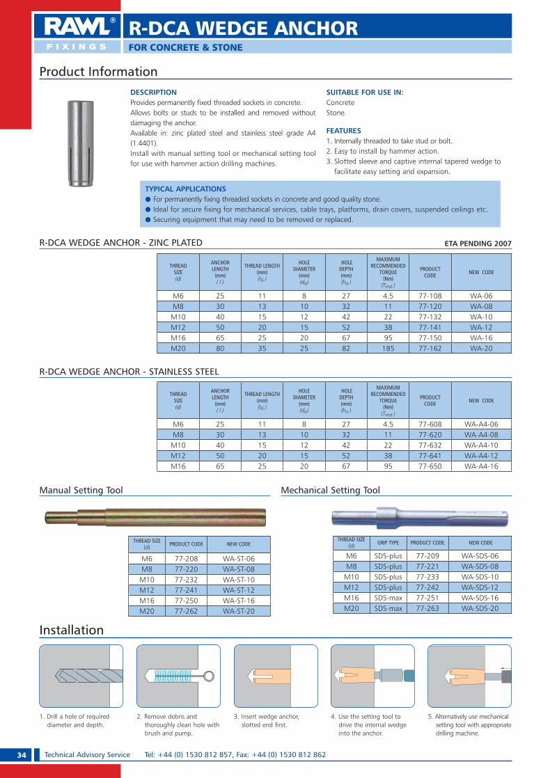
34 Technical Advisory Service Tel: +44 (0) 1530 812 857, Fax: +44 (0) 1530 812 862
R-DCA WEDGE ANCHORFOR CONCRETE & STONE
DESCRIPTIONProvides permanently fixed threaded sockets in concrete. Allows bolts or studs to be installed and removed without damaging the anchor. Available in: zinc plated steel and stainless steel grade A4 (1.4401). Install with manual setting tool or mechanical setting tool for use with hammer action drilling machines.
SUITABLE FOR USE IN:ConcreteStone.
FEATURES1. Internally threaded to take stud or bolt.2. Easy to install by hammer action.3. Slotted sleeve and captive internal tapered wedge to
facilitate easy setting and expansion.
Product Information
Installation
1. Drill a hole of required diameter and depth.
2. Remove debris and thoroughly clean hole with brush and pump.
3. Insert wedge anchor, slotted end first.
5. Alternatively use mechanical setting tool with appropriate drilling machine.
4. Use the setting tool to drive the internal wedge into the anchor.
R-DCA WEDGE ANCHOR - ZINC PLATED
THREADSIZE(d)
ANCHORLENGTH
(mm)( l )
THREAD LENGTH(mm)(lG )
HOLE DIAMETER
(mm)(do)
HOLE DEPTH(mm)(ho )
MAXIMUMRECOMMENDED
TORQUE(Nm)
(Tinst )
PRODUCT CODE NEW CODE
M6 25 11 8 27 4.5 77-108 WA-06M8 30 13 10 32 11 77-120 WA-08
M10 40 15 12 42 22 77-132 WA-10M12 50 20 15 52 38 77-141 WA-12M16 65 25 20 67 95 77-150 WA-16M20 80 35 25 82 185 77-162 WA-20
Manual Setting Tool
THREAD SIZE(d) PRODUCT CODE NEW CODE
M6 77-208 WA-ST-06M8 77-220 WA-ST-08
M10 77-232 WA-ST-10M12 77-241 WA-ST-12M16 77-250 WA-ST-16M20 77-262 WA-ST-20
Mechanical Setting Tool
THREAD SIZE(d) GRIP TYPE PRODUCT CODE NEW CODE
M6 SDS-plus 77-209 WA-SDS-06M8 SDS-plus 77-221 WA-SDS-08M10 SDS-plus 77-233 WA-SDS-10M12 SDS-plus 77-242 WA-SDS-12M16 SDS-max 77-251 WA-SDS-16M20 SDS-max 77-263 WA-SDS-20
R-DCA WEDGE ANCHOR - STAINLESS STEEL
THREADSIZE(d)
ANCHORLENGTH
(mm)( l )
THREAD LENGTH(mm)(lG )
HOLE DIAMETER
(mm)(do)
HOLE DEPTH(mm)(ho )
MAXIMUMRECOMMENDED
TORQUE(Nm)
(Tinst )
PRODUCT CODE NEW CODE
M6 25 11 8 27 4.5 77-608 WA-A4-06M8 30 13 10 32 11 77-620 WA-A4-08
M10 40 15 12 42 22 77-632 WA-A4-10M12 50 20 15 52 38 77-641 WA-A4-12M16 65 25 20 67 95 77-650 WA-A4-16
ETA PENDING 2007
TYPICAL APPLICATIONSe For permanently fixing threaded sockets in concrete and good quality stone.e Ideal for secure fixing for mechanical services, cable trays, platforms, drain covers, suspended ceilings etc.e Securing equipment that may need to be removed or replaced.
RAWL_KATALOG_2007_2008.indb 34RAWL_KATALOG_2007_2008.indb 34 2007-10-15 14:34:422007-10-15 14:34:42

35Technical Advisory Service e-mail: [email protected] OR [email protected]
FOR CONCRETE & STONE
R-DCA WEDGE ANCHOR
For further explanations on calculations please see pages 10 and 11
Speci� cation Data
R-DCA WEDGE ANCHOR Performance Data
SIZE
CONCRETE, fck,cube = 30N/mm2 (C20/25)
CHARACTERISTIC RESISTANCE (kN)
DESIGN RESISTANCE (Factored) (kN)
RECOMMENDED LOAD (Unfactored) (kN)
CHARACTERISTIC EDGE DISTANCE (mm) *
CHARACTERISTIC SPACING (mm)
TENSION (NRk)
SHEAR(VRk)
TENSION (NRd)
SHEAR(VRd)
TENSION (Nrec)
SHEAR (Vrec)
TENSION (Ccr,N)
SHEAR(Ccr,V)
TENSION & SHEAR (Scr,N) (Scr,V)
M6 7.9 4.3 3.7 2.4 3.1 2.0 80 80 90
M8 9.5 7.5 4.4 4.1 3.7 3.4 90 90 110
M10 15.9 11.8 7.4 6.6 6.2 5.5 120 120 140
M12 20.3 17.2 9.4 9.6 7.8 8.0 160 160 170
M16 31.8 32.0 14.7 17.8 12.3 14.8 220 220 250
M20 43.1 49.9 20.0 27.7 16.7 23.1 250 250 300
Reduction Factors - Edge and Spacing Distances for Wedge AnchorThe full characteristic edge and spacing distances shown in the table above are the minimum allowable for the quoted DESIGN RESISTANCE or RECOMMENDED LOAD, depending on your design method.Where these dimensions are not achievable,
the appropriate reduction factor/s from the tables below must be applied to the DESIGN RESISTANCE or RECOMMENDED LOAD.Choose the required bolt diameter across the top of the appropriate table and read down the left hand column until actual edge or spacing distance is found. Read off the reduction factor where the two
lines intersect (interpolate as required). Multiply this factor by the DESIGN RESISTANCE or RECOMMENDED LOAD quoted in the table.On the occasion that multiple close edge and/or spacing distances occur, the appropriate reduction factors must be applied.
Minimum Edge Distance (Concrete Only)
EDGE (mm)
TENSILE: EDGE REDUCTION FACTORS EDGE (mm)
SHEAR: EDGE REDUCTION FACTORS
M6 M8 M10 M12 M16 M20 M6 M8 M10 M12 M16 M20
70 7080 1.00 80 1.0090 1.00 90 1.00100 100120 1.00 120 1.00140 140160 1.00 160 1.00190 190220 1.00 220 1.00250 1.00 250 1.00
Spacing (Concrete Only)
SPACING(mm)
TENSILE & SHEAR REDUCTION FACTORS
M6 M8 M10 M12 M16 M20
50 0.8060 0.85 0.8070 0.90 0.84 0.8090 1.00 0.92 0.86 0.80110 1.00 0.91 0.85 0.80140 1.00 0.93 0.84 0.80170 1.00 0.88 0.84210 0.94 0.89250 1.00 0.94300 1.00
* It is recommended that Wedge anchors are not installed below the “characteristic” edge distances quoted in the table above.
RAWL_KATALOG_2007_2008.indb 35RAWL_KATALOG_2007_2008.indb 35 2007-10-15 14:34:522007-10-15 14:34:52

36 Technical Advisory Service Tel: +44 (0) 1530 812 857, Fax: +44 (0) 1530 812 862
R-DCL LIPPED WEDGE ANCHORFOR CONCRETE & STONE
DESCRIPTIONThe Lipped Wedge Anchor provides an easy to install fixing.Allows for bolts and studs to be installed and removed without effecting the anchor. Available in zinc plated steel.Install with manual setting tool or mechanical setting tool for use with hammer action drilling machines.
SUITABLE FOR USE IN:ConcreteStone.
FEATURES1. Internally threaded to take stud or bolt.2. Easy to install flush to the surface.3. Ideal for setting in cavity ceilings.
Product Information
Installation
1. Drill a hole of required diameter and depth.
2. Remove debris and thoroughly clean hole with brush and pump.
3. Insert wedge anchor, slotted end first.
5. Alternatively use mechanical setting tool with appropriate drilling machine.
4. Use the setting tool to drive the internal wedge into the anchor.
R-DCL WEDGE ANCHOR - Zinc plated
THREADSIZE(d)
ANCHORLENGTH
(mm)( l )
THREAD LENGTH
(mm)(lG )
HOLE DIAMETER
(mm)(do)
HOLE DEPTH(mm)(ho )
MAXIMUMRECOMMENDED
TORQUE(Nm)
(Tinst )
PRODUCT CODE NEW CODE
M6 25 11 8 27 4.5 77-908 LWA-06L
M8 30 13 10 32 11 77-920 LWA-08L
M10 40 15 12 42 22 77-932 LWA-10L
M12 50 20 15 52 38 77-941 LWA-12L
M16 65 25 20 67 95 77-950 LWA-16L
Manual Setting Tool
THREAD SIZE(d) NEW CODE PRODUCT CODE
M6 77-208 WAN-ST-06-W1
M8 77-220 WAN-ST-08-W1
M10 77-232 WAN-ST-10-W1
M12 77-241 WAN-ST-12-W1
M16 77-250 WAN-ST-16-W1
Mechanical Setting Tool
THREAD SIZE(d) GRIP TYPE NEW CODE PRODUCT CODE
M6 SDS-plus 77-209 WAN-SDS-06-W1
M8 SDS-plus 77-221 WAN-SDS-08-W1
M10 SDS-plus 77-233 WAN-SDS-10-W1
M12 SDS-plus 77-242 WAN-SDS-12-W1
M16 SDS-max 77-251 WAN-SDS-16-W1
ETA PENDING 2007
TYPICAL APPLICATIONSe Fixing mechanical servicese Cable trayse Platformse Drain coverse Suspended ceilings.
RAWL_KATALOG_2007_2008.indb 36RAWL_KATALOG_2007_2008.indb 36 2007-10-15 14:34:532007-10-15 14:34:53
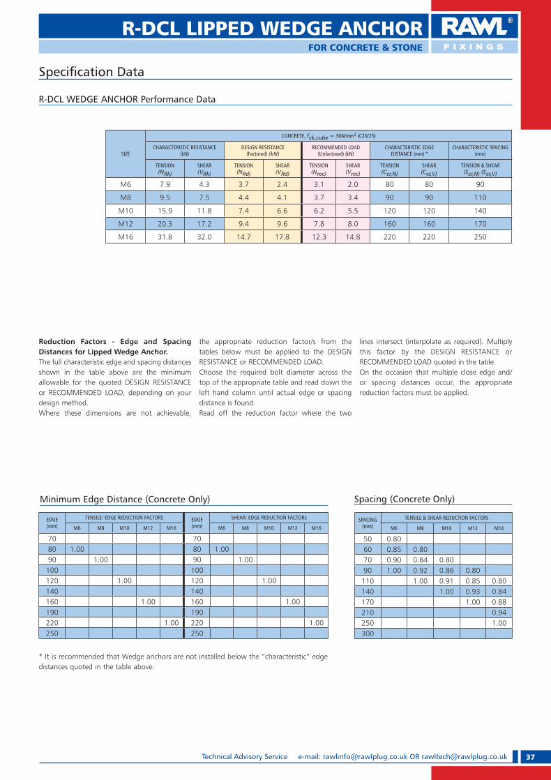
37Technical Advisory Service e-mail: [email protected] OR [email protected]
R-DCL LIPPED WEDGE ANCHORFOR CONCRETE & STONE
Speci� cation Data
R-DCL WEDGE ANCHOR Performance Data
SIZE
CONCRETE, fck,cube = 30N/mm2 (C20/25)
CHARACTERISTIC RESISTANCE (kN)
DESIGN RESISTANCE (Factored) (kN)
RECOMMENDED LOAD (Unfactored) (kN)
CHARACTERISTIC EDGE DISTANCE (mm) *
CHARACTERISTIC SPACING (mm)
TENSION (NRk)
SHEAR(VRk)
TENSION (NRd)
SHEAR(VRd)
TENSION (Nrec)
SHEAR (Vrec)
TENSION (Ccr,N)
SHEAR(Ccr,V)
TENSION & SHEAR (Scr,N) (Scr,V)
M6 7.9 4.3 3.7 2.4 3.1 2.0 80 80 90
M8 9.5 7.5 4.4 4.1 3.7 3.4 90 90 110
M10 15.9 11.8 7.4 6.6 6.2 5.5 120 120 140
M12 20.3 17.2 9.4 9.6 7.8 8.0 160 160 170
M16 31.8 32.0 14.7 17.8 12.3 14.8 220 220 250
Reduction Factors - Edge and Spacing Distances for Lipped Wedge Anchor.The full characteristic edge and spacing distances shown in the table above are the minimum allowable for the quoted DESIGN RESISTANCE or RECOMMENDED LOAD, depending on your design method.Where these dimensions are not achievable,
the appropriate reduction factor/s from the tables below must be applied to the DESIGN RESISTANCE or RECOMMENDED LOAD.Choose the required bolt diameter across the top of the appropriate table and read down the left hand column until actual edge or spacing distance is found. Read off the reduction factor where the two
lines intersect (interpolate as required). Multiply this factor by the DESIGN RESISTANCE or RECOMMENDED LOAD quoted in the table.On the occasion that multiple close edge and/or spacing distances occur, the appropriate reduction factors must be applied.
Minimum Edge Distance (Concrete Only)
EDGE (mm)
TENSILE: EDGE REDUCTION FACTORS EDGE (mm)
SHEAR: EDGE REDUCTION FACTORS
M6 M8 M10 M12 M16 M6 M8 M10 M12 M16
70 7080 1.00 80 1.0090 1.00 90 1.00100 100120 1.00 120 1.00140 140160 1.00 160 1.00190 190220 1.00 220 1.00250 250
Spacing (Concrete Only)
SPACING(mm)
TENSILE & SHEAR REDUCTION FACTORS
M6 M8 M10 M12 M16
50 0.8060 0.85 0.8070 0.90 0.84 0.8090 1.00 0.92 0.86 0.80110 1.00 0.91 0.85 0.80140 1.00 0.93 0.84170 1.00 0.88210 0.94250 1.00300
* It is recommended that Wedge anchors are not installed below the “characteristic” edge distances quoted in the table above.
RAWL_KATALOG_2007_2008.indb 37RAWL_KATALOG_2007_2008.indb 37 2007-10-15 14:35:022007-10-15 14:35:02
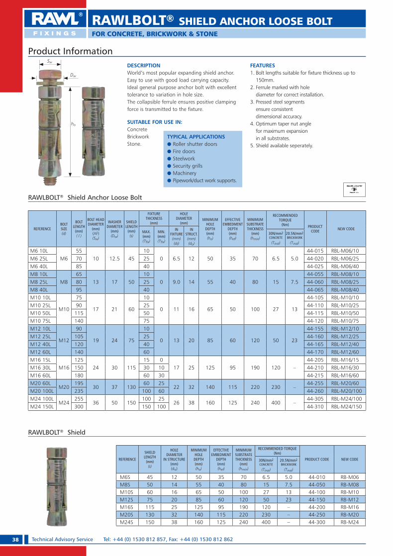
38 Technical Advisory Service Tel: +44 (0) 1530 812 857, Fax: +44 (0) 1530 812 862
DESCRIPTIONWorld’s most popular expanding shield anchor. Easy to use with good load carrying capacity.Ideal general purpose anchor bolt with excellent tolerance to variation in hole size.The collapsible ferrule ensures positive clamping force is transmitted to the fixture.
SUITABLE FOR USE IN:ConcreteBrickworkStone.
FEATURES1. Bolt lengths suitable for fixture thickness up to
150mm.2. Ferrule marked with hole
diameter for correct installation.3. Pressed steel segments
ensure consistent dimensional accuracy.
4. Optimum taper nut angle for maximum expansion in all substrates.
5. Shield available seperately.
Product Information
RAWLBOLT® Shield Anchor Loose Bolt
REFERENCEBOLT SIZE(d)
BOLTLENGTH
(mm)( l )
BOLT HEAD DIAMETER
(mm)(AF)(Sw)
WASHER DIAMETER
(mm)(Dw)
SHIELDLENGTH
(mm)(s)
FIXTURE THICKNESS
(mm)
HOLE DIAMETER
(mm) MINIMUM
HOLEDEPTH(mm)(ho)
EFFECTIVE EMBEDMENT
DEPTH(mm)(hef)
MINIMUMSUBSTRATE THICKNESS
(mm)(hmin)
RECOMMENDED TORQUE
(Nm) PRODUCT CODE NEW CODE
MAX.(mm)(T� x)
MIN.(mm)(T� x)
IN FIXTURE(mm)(df)
IN STRUCT.(mm)(do)
30N/mm2CONCRETE
(Tinst)
20.5N/mm2BRICKWORK
(Tinst)
M6 10LM6
5510 12.5 45
100 6.5 12 50 35 70 6.5 5.0
44-015 RBL-M06/10M6 25L 70 25 44-020 RBL-M06/25M6 40L 85 40 44-025 RBL-M06/40M8 10L
M865
13 17 5010
0 9.0 14 55 40 80 15 7.544-055 RBL-M08/10
M8 25L 80 25 44-060 RBL-M08/25M8 40L 95 40 44-065 RBL-M08/40M10 10L
M10
75
17 21 60
10
0 11 16 65 50 100 27 13
44-105 RBL-M10/10M10 25L 90 25 44-110 RBL-M10/25M10 50L 115 50 44-115 RBL-M10/50M10 75L 140 75 44-120 RBL-M10/75M12 10L
M12
90
19 24 75
10
0 13 20 85 60 120 50 23
44-155 RBL-M12/10M12 25L 105 25 44-160 RBL-M12/25M12 40L 120 40 44-165 RBL-M12/40M12 60L 140 60 44-170 RBL-M12/60M16 15L
M16125
24 30 11515 0
17 25 125 95 190 120 –44-205 RBL-M16/15
M16 30L 150 30 10 44-210 RBL-M16/30M16 60L 180 60 30 44-215 RBL-M16/60M20 60L
M20195
30 37 13060 25
22 32 140 115 220 230 –44-255 RBL-M20/60
M20 100L 235 100 60 44-260 RBL-M20/100M24 100L
M24255
36 50 150100 25
26 38 160 125 240 400 –44-305 RBL-M24/100
M24 150L 300 150 100 44-310 RBL-M24/150
RAWLBOLT® SHIELD ANCHOR LOOSE BOLTFOR CONCRETE, BRICKWORK & STONE
ho
Sw
Dw
REFERENCE
SHIELDLENGTH
(mm)(s)
HOLE DIAMETER
IN STRUCTURE(mm)(do)
MINIMUM HOLE
DEPTH(mm)(ho)
EFFECTIVE EMBEDMENT
DEPTH(mm)(hef)
MINIMUMSUBSTRATE THICKNESS
(mm)(hmin)
RECOMMENDED TORQUE(Nm)
PRODUCT CODE NEW CODE30N/mm2CONCRETE
(Tinst)
20.5N/mm2BRICKWORK
(Tinst)
M6S 45 12 50 35 70 6.5 5.0 44-010 RB-M06M8S 50 14 55 40 80 15 7.5 44-050 RB-M08M10S 60 16 65 50 100 27 13 44-100 RB-M10M12S 75 20 85 60 120 50 23 44-150 RB-M12M16S 115 25 125 95 190 120 – 44-200 RB-M16M20S 130 32 140 115 220 230 – 44-250 RB-M20M24S 150 38 160 125 240 400 – 44-300 RB-M24
RAWLBOLT® Shield
TYPICAL APPLICATIONSe Roller shutter doorse Fire doorse Steelworke Security grillse Machinerye Pipework/duct work supports.
RAWL_KATALOG_2007_2008.indb 38RAWL_KATALOG_2007_2008.indb 38 2007-10-15 14:35:042007-10-15 14:35:04
39Technical Advisory Service e-mail: [email protected] OR [email protected]
Speci� cation Data
1. Drill a hole of required diameter and depth. Note: When fixing into brickwork, mortar joints should be avoided.
2. Remove debris and thoroughly clean hole with brush and pump.
3. Remove bolt and washer. Insert shield and place fixture over the hole.
4. Insert bolt with washer through the fixture and tighten to the recommended torque.
Installation
RAWLBOLT® Shield Anchor Loose Bolt Performance Data
SIZE
CONCRETE, fck,cube = 30N/mm2 (C20/25) Brickwork = 20.5 N/mm2
CHARACTERISTIC RESISTANCE (kN)
DESIGN RESISTANCE (Factored) (kN)
RECOMMENDED LOAD (Unfactored) (kN)
CHARACTERISTIC EDGE DISTANCE (mm)
CHARACTERISTIC SPACING (mm)
RECOMMENDED LOAD (Unfactored) (kN)
TENSION (NRk)
SHEAR(VRk)
TENSION (NRd)
SHEAR(VRd)
TENSION (Nrec)
SHEAR (Vrec)
TENSION (Ccr,N)
SHEAR(Ccr,V)
TENSION & SHEAR (Scr,N) (Scr,V)
TENSION & SHEAR (Nrec) (Vrec)
M6 9.6 8.2 4.5 4.5 3.8 3.8 80 100 120 1.8
M8 12.1 12.8 5.6 7.1 4.7 5.9 100 120 150 2.3
M10 16.7 20.9 7.7 11.6 6.4 9.7 120 160 180 2.9
M12 24.6 30.5 11.4 16.9 9.5 14.1 160 180 250 4.3
M16 57.4 55.3 26.6 30.7 22.2 25.6 190 260 290Bolts above M12
are not recommended in brickwork.
M20 79.4 88.1 36.8 48.9 30.7 40.8 250 300 330 When calculating loads in brickwork, apply the published edge distance and spacing for
concrete and assume these figures to be the absolute minimums.
Concrete reduction factors must NOT be applied.
M24 99.0 122.8 45.8 68.2 38.2 56.8 280 350 420
For further explanations on calculations please see pages 10 and 11
Reduction Factors - Edge and Spacing Distances for Rawlbolt Shield Anchor Loose BoltThe full characteristic edge and spacing distances shown in the table above are the minimum allowable for the quoted DESIGN RESISTANCE or RECOMMENDED LOAD, depending on your design method.
Where these dimensions are not achievable, the appropriate reduction factor/s from the tables below must be applied to the DESIGN RESISTANCE or RECOMMENDED LOAD.Choose the required bolt diameter across the top of the appropriate table and read down the left hand column until actual edge or spacing distance is found.
Read off the reduction factor where the two lines intersect (interpolate as required). Multiply this factor by the DESIGN RESISTANCE or RECOMMENDED LOAD quoted in the table. On the occasion that multiple close edge and/or spacing distances occur, the appropriate reduction factors must be applied.
Edge Distance (Concrete Only)
EDGE (mm)
TENSILE: EDGE REDUCTION FACTORS EDGE (mm)
SHEAR: EDGE REDUCTION FACTORS
M6 M8 M10 M12 M16 M20 M24 M6 M8 M10 M12 M16 M20 M24
50 0.70 60 0.5060 0.80 0.70 70 0.6470 0.90 0.80 0.70 80 0.76 0.5080 1.00 0.90 0.80 0.70 100 1.00 0.75 0.50
100 1.00 0.90 0.78 0.70 120 1.00 0.69 0.50120 1.00 0.85 0.78 0.70 160 1.00 0.85140 0.93 0.85 0.76 0.70 170 0.93 0.50160 1.00 0.93 0.82 0.76 180 1.00 0.55190 1.00 0.88 0.82 220 0.76 0.50220 0.94 0.88 260 1.00 0.75 0.50250 1.00 0.94 300 1.00 0.75280 1.00 350 1.00
Spacing (Concrete Only)
SPACING(mm)
TENSILE & SHEAR REDUCTION FACTORS
M6 M8 M10 M12 M16 M20 M24
60 0.7080 0.80 0.70100 0.90 0.80 0.70120 1.00 0.90 0.80 0.70150 1.00 0.90 0.78 0.70180 1.00 0.85 0.78 0.70210 0.93 0.85 0.78 0.70250 1.00 0.93 0.85 0.76290 1.00 0.93 0.82330 1.00 0.88370 0.94420 1.00
Brickwork ApplicationWhen installing into brickwork and there is a combined load in tension and shear, the resultant load must not exceed the quoted performance figure.
RAWLBOLT® SHIELD ANCHOR LOOSE BOLT
RAWL_KATALOG_2007_2008.indb 39RAWL_KATALOG_2007_2008.indb 39 2007-10-15 14:35:082007-10-15 14:35:08

40 Technical Advisory Service Tel: +44 (0) 1530 812 857, Fax: +44 (0) 1530 812 862
DESCRIPTIONWorld’s most popular expanding shield anchor. Easy to use with good load carrying capacity.Ideal general purpose anchor bolt with excellent tolerance to variation in hole size.The collapsible ferrule ensures positive clamping force is transmitted to the fixture.
SUITABLE FOR USE IN:ConcreteBrickworkStone.
FEATURES1. Provides a projecting stud to support fixture
during installation and removal.2. Ferrule marked with hole diameter for correct
installation.3. Pressed steel segments ensure consistent
dimensional accuracy.4. Optimum taper nut angle for maximum
expansion in all substrates.
Product Information
RAWLBOLT® Shield Anchor Bolt Projecting
REFERENCEBOLT SIZE(d)
BOLTLENGTH
(mm)( l )
NUT DIAMETER
(mm)(AF)(Sw)
WASHER DIAMETER
(mm)(Dw)
SHIELDLENGTH
(mm)(s)
FIXTURE THICKNESS
(mm)
HOLE DIAMETER(mm) MINIMUM
HOLEDEPTH(mm)(ho)
EFFECTIVE EMBEDMENT
DEPTH(mm)(hef)
MINIMUMSUBSTRATE THICKNESS
(mm)(hmin)
RECOMMENDED TORQUE
(Nm) PRODUCT CODE NEW CODE
MAX.(mm)(T� x)
MIN.(mm)(T� x)
IN FIXTURE
(mm)(df)
IN STRUCT.
(mm)(do)
30N/mm2CONCRETE
(Tinst)
20.5N/mm2BRICKWORK
(Tinst)
M6 10PM6
6510 12.5 45
100 6.5 12 50 35 70 6.5 5.0
44-505 RBP-M06/10M6 25P 80 25 44-510 RBP-M06/25M6 60P 15 60 44-515 RBP-M06/60M8 10P
M875
13 17 5010
0 9.0 14 55 40 80 15 7.544-555 RBP-M08/10
M8 25P 90 25 44-560 RBP-M08/25M8 60P 125 60 44-565 RBP-M08/60M10 15P
M1090
17 21 6015
0 11 16 65 50 100 27 1344-605 RBP-M10/15
M10 30P 105 30 44-610 RBP-M10/30M10 60P 135 60 44-615 RBP-M10/60M12 15P
M12110
19 24 7515
0 13 20 85 60 120 50 2344-655 RBP-M12/15
M12 30P 125 30 44-660 RBP-M12/30M12 75P 170 75 44-665 RBP-M12/75M16 15P
M16150
24 30 11515 0
17 25 125 95 190 120 –44-705 RBP-M16/15
M16 35P 170 35 10 44-710 RBP-M16/35M16 75P 210 75 35 44-715 RBP-M16/75M20 15P
M20170
30 37 13015 0
22 32 140 115 220 230 –44-755 RBP-M20/15
M20 30P 185 30 10 44-760 RBP-M20/30M20 100P 255 100 30 44-765 RBP-M20/100M24 75P
M24255
36 50 15075 0
26 38 160 125 240 400 –44-805 RBP-M24/75
M24 120P 300 120 75 44-810 RBP-M24/150
ho
Sw
Dw
1. Drill a hole of required diameter and depth. Note: When fixing into brickwork, mortar joints should be avoided.
2. Remove debris and thoroughly clean hole with brush and pump.
3. Remove nut and washer and insert anchor into hole. Position fixture over the thread.
4. Add washer and nut and tighten to recommended torque.
Installation
RAWLBOLT® SHIELD ANCHOR BOLT PROJECTINGFOR CONCRETE, BRICKWORK & STONE
TYPICAL APPLICATIONSe Roller shutter doorse Fire doorse Wall platese Security grillse Machinerye Signs e Fencing.
RAWL_KATALOG_2007_2008.indb 40RAWL_KATALOG_2007_2008.indb 40 2007-10-15 14:35:102007-10-15 14:35:10

41Technical Advisory Service e-mail: [email protected] OR [email protected]
Speci� cation Data
RAWLBOLT® Shield Anchor Bolt Projecting Performance Data
SIZE
CONCRETE, fck,cube = 30N/mm2 (C20/25) BRICKWORK = 20.5 N/mm2
CHARACTERISTIC RESISTANCE (kN)
DESIGN RESISTANCE (Factored) (kN)
RECOMMENDED LOAD (Unfactored) (kN)
CHARACTERISTIC EDGE DISTANCE (mm)
CHARACTERISTIC SPACING (mm)
RECOMMENDED LOAD (Unfactored) (kN)
TENSION (NRk)
SHEAR(VRk)
TENSION (NRd)
SHEAR(VRd)
TENSION (Nrec)
SHEAR (Vrec)
TENSION (Ccr,N)
SHEAR(Ccr,V)
TENSION & SHEAR (Scr,N) (Scr,V)
TENSION & SHEAR (Nrec) (Vrec)
M6 9.6 8.2 4.5 4.5 3.8 3.8 80 100 120 1.8
M8 12.1 12.8 5.6 7.1 4.7 5.9 100 120 150 2.3
M10 16.7 20.9 7.7 11.6 6.4 9.7 120 160 180 2.9
M12 24.6 30.5 11.4 16.9 9.5 14.1 160 180 250 4.3
M16 57.4 55.3 26.6 30.7 22.2 25.6 190 260 290Bolts above M12
are not recommended in brickwork.
M20 79.4 88.1 36.8 48.9 30.7 40.8 250 300 330When calculating loads in
brickwork, apply the published edge distance and spacing for
concrete and assume these figures to be the absolute minimums.
Concrete reduction factors must NOT be applied.
M24 99.0 122.8 45.8 68.2 38.2 56.8 280 350 420
For further explanations on calculations please see pages 10 and 11
Reduction Factors - Edge and Spacing Distances for Rawlbolt Bolt ProjectingThe full characteristic edge and spacing distances shown in the table above are the minimum allowable for the quoted DESIGN RESISTANCE or RECOMMENDED LOAD, depending on your design method.Where these dimensions are not achievable,
the appropriate reduction factor/s from the tables below must be applied to the DESIGN RESISTANCE or RECOMMENDED LOAD. Choose the required bolt diameter across the top of the appropriate table and read down the left hand column until actual edge or spacing distance is found. Read off the reduction factor where the two lines intersect (interpolate as required).
Multiply this factor by the DESIGN RESISTANCE or RECOMMENDED LOAD quoted in the table. On the occasion that multiple close edge and/or spacing distances occur, the appropriate reduction factors must be applied.
Edge Distance (Concrete Only)
EDGE (mm)
TENSILE: EDGE REDUCTION FACTORS EDGE (mm)
SHEAR: EDGE REDUCTION FACTORS
M6 M8 M10 M12 M16 M20 M24 M6 M8 M10 M12 M16 M20 M24
50 0.70 60 0.5060 0.80 0.70 70 0.6470 0.90 0.80 0.70 80 0.76 0.5080 1.00 0.90 0.80 0.70 100 1.00 0.75 0.50100 1.00 0.90 0.78 0.70 120 1.00 0.69 0.50120 1.00 0.85 0.78 0.70 160 1.00 0.85140 0.93 0.85 0.76 0.70 170 0.93 0.50160 1.00 0.93 0.82 0.76 180 1.00 0.55190 1.00 0.88 0.82 220 0.76 0.50220 0.94 0.88 260 1.00 0.75 0.50250 1.00 0.94 300 1.00 0.75280 1.00 350 1.00
Spacing (Concrete Only)
SPACING(mm)
TENSILE & SHEAR REDUCTION FACTORS
M6 M8 M10 M12 M16 M20 M24
60 0.7080 0.80 0.70100 0.90 0.80 0.70120 1.00 0.90 0.80 0.70150 1.00 0.90 0.78 0.70180 1.00 0.85 0.78 0.70210 0.93 0.85 0.78 0.70250 1.00 0.93 0.85 0.76290 1.00 0.93 0.82330 1.00 0.88370 0.94420 1.00
Brickwork ApplicationWhen installing into brickwork and there is a combined load in tension and shear, the resultant load must not exceed the quoted performance figure.
RAWLBOLT® SHIELD ANCHOR BOLT PROJECTINGFOR CONCRETE, BRICKWORK & STONE
RAWL_KATALOG_2007_2008.indb 41RAWL_KATALOG_2007_2008.indb 41 2007-10-15 14:35:122007-10-15 14:35:12

42 Technical Advisory Service Tel: +44 (0) 1530 812 857, Fax: +44 (0) 1530 812 862
DESCRIPTIONSuitable for temporary or permanent anchorage.Supplied complete with shield, washer and hex nut.Must not be used for safety harness applications or for lifting where shock load could be applied.
SUITABLE FOR USE IN:ConcreteBrickworkStone.
FEATURES1. Eye designed & manufactured for maximum
performance.2. Ferrule marked with hole diameter to ensure
correct installation.3. Pressed steel segments ensure consistent dimensional accuracy.4. Optimum geometry taper angle for maximum expansion in all substrates.
Product Information
1. Drill a hole of required diameter and depth. Note: When fixing into brickwork, mortar joints should be avoided.
2. Remove debris and thoroughly clean hole with brush and pump.
3. Insert the Eye Bolt and position accordingly.
Installation
4. Tighten to recommended torque, using the nut (not the eye).
RAWLBOLT® Shield Anchor Eye Bolt
REFERENCEBOLT SIZE(d)
SHIELDLENGTH
(mm)(s)
OVERALL LENGTH
(mm)(l)
HOLE DIAMETER
IN STRUCTURE(mm) (do)
MINIMUM HOLE
DEPTH(mm)(ho)
EFFECTIVE EMBEDMENT
DEPTH(mm)(hef)
APPROXIMATEDIAMETER
IN EYE(mm)(E)
RECOMMENDED TORQUE(Nm)
PRODUCT CODE NEW CODE30N/mm2
CONCRETE
(Tinst)
20.5N/mm2 BRICKWORK
(Tinst)
M6E M6 45 73 12 50 35 10 6.5 5 44-432 RBL-06EM8E M8 50 87 14 55 40 12 15 7.5 44-437 RBL-08E
M10E M10 60 108 16 65 50 14 27 13 44-442 RBL-10EM12E M12 75 130 20 85 60 17 50 23 44-447 RBL-12E
RAWLBOLT® SHIELD ANCHOR EYE BOLT
Speci� cation Data (Concrete Only)
RAWLBOLT® Shield Anchor Eye Bolt Performance Data
SIZE
CONCRETE, fck,cube = 30N/mm2 (C20/25)
CHARACTERISTIC RESISTANCE (kN)
DESIGN RESISTANCE (Factored) (kN)
RECOMMENDED LOAD (Unfactored) (kN)
CHARACTERISTIC EDGE DISTANCE
(mm)
CHARACTERISTIC SPACING
(mm)
RECOMMENDED LOAD (Unfactored) (kN)
CHARACTERISTIC EDGE DISTANCE
(mm)
CHARACTERISTIC SPACING
(mm)
TENSION (NRk)
TENSION (NRd)
TENSION (Nrec)
TENSION ( Ccr,N )
TENSION(Scr,N )
OBLIQUE 45o
(Frec )SHEAR
( Ccr,V )SHEAR
(Scr,V )
M6 5.3 2.4 2.0 80 120 0.57 70 80
M8 9.6 4.5 3.8 100 150 1.67 85 100
M10 15.2 7.0 5.8 120 180 2.31 100 120
M12 22.1 10.2 8.5 160 250 3.23 130 160
For further explanations on calculations please see pages 10 and 11
For brickwork data in tension only, refer to standard Rawlbolt brickwork table on preceding pages
FOR CONCRETE, BRICKWORK & STONE
hoTYPICAL APPLICATIONSe Supporting guy ropes, stays
& cables.e Supporting ladder restraints.
RAWL_KATALOG_2007_2008.indb 42RAWL_KATALOG_2007_2008.indb 42 2007-10-15 14:35:132007-10-15 14:35:13

43Technical Advisory Service e-mail: [email protected] OR [email protected]
DESCRIPTIONSuitable for temporary or permanent anchorage.Supplied complete with shield, washer and hex nut.Must not be used for safety harness applications or for lifting where shock load could be applied.
SUITABLE FOR USE IN:ConcreteBrickworkStone.
FEATURES1. Eye designed & manufactured for maximum
performance.2. Ferrule marked with hole diameter to ensure
correct installation.3. Pressed steel segments ensure consistent dimensional accuracy.4. Optimum geometry taper angle for maximum expansion in all substrates.
Product Information
ho
1. Drill a hole of required diameter and depth. Note: When fixing into brickwork, mortar joints should be avoided.
2. Remove debris and thoroughly clean hole with brush and pump.
3. Insert the Hook Bolt and position accordingly.
Installation
4. Tighten to recommended torque, using the nut (not the hook).
RAWLBOLT® Shield Anchor Hook Bolt
REFERENCEBOLT SIZE(d)
SHIELDLENGTH
(mm)(s)
OVERALL LENGTH
(mm)(l)
HOLE DIAMETER
IN STRUCTURE(mm) (do)
MINIMUM HOLE
DEPTH(mm)(ho)
EFFECTIVE EMBEDMENT
DEPTH(mm)(hef)
APPROXIMATEDIAMETERIN HOOK
(mm)(H)
RECOMMENDED TORQUE(Nm)
PRODUCT CODE NEW CODE30N/mm2
CONCRETE
(Tinst)
20.5N/mm2BRICKWORK
(Tinst)
M6H M6 45 83 12 50 35 8 6.5 5 44-401 RBL-06HM8H M8 50 98 14 55 40 10 15 7.5 44-406 RBL-08H
M10H M10 60 120 16 65 50 12 27 13 44-411 RBL-10HM12H M12 75 145 20 85 60 16 50 23 44-416 RBL-12H
Speci� cation Data
RAWLBOLT® Shield Anchor Hook Bolt Performance Data
SIZE
BRICKWORK AND CONCRETE, fck,cube = 30N/mm2 (C20/25)
CHARACTERISTIC RESISTANCE (kN)
DESIGN RESISTANCE (Factored) (kN)
RECOMMENDED LOAD (Unfactored) (kN)
CHARACTERISTIC EDGE DISTANCE
(mm)
CHARACTERISTIC SPACING
(mm)
Tension (NRk)
Tension (NRd)
Tension (Nrec)
Tension ( Ccr,N )
Tension(Scr,N )
M6 2.2 1.0 0.8 70 80
M8 4.2 1.9 1.6 85 100
M10 6.5 3.0 2.5 100 120
M12 9.4 4.3 3.6 120 140
For further explanations on calculations please see pages 10 and 11
RAWLBOLT® SHIELD ANCHOR HOOK BOLTFOR CONCRETE, BRICKWORK & STONE
H
TYPICAL APPLICATIONSe Supporting guy ropes, stays
& cables.e Supporting ladder restraints.
RAWL_KATALOG_2007_2008.indb 43RAWL_KATALOG_2007_2008.indb 43 2007-10-15 14:35:162007-10-15 14:35:16

44 Technical Advisory Service Tel: +44 (0) 1530 812 857, Fax: +44 (0) 1530 812 862
RAWLOK® BOLT PROJECTINGFOR CONCRETE, BRICK, BLOCK & STONE
DESCRIPTIONThe Rawlok® is a torque controlled expansion anchor comprising a split sleeve and a bolt incorporating an expander wedge. It is a through fixing, thus allowing the hole in the substrate to be drilled through the pre-positioned fixture, eliminating the need for marking out, ensuring fast and simple installation.
SUITABLE FOR USE IN:ConcreteBrickworkBlockworkStone.
FEATURES1. Bolt and drill size marked
on sleeve to ensure correct installation.2. Integral collapse feature to ensure maximum
clamping force is applied to the fixture.3. Anchor designed for optimum performance in
most base material types.3. One piece flange nut.
Product Information
RAWLOK® Bolt Projecting - Zinc plated
minimum ho
Dw
Sw
1. Drill a hole of required diameter and depth. Note: Fixing into mortar joints should be avoided.
2. Remove debris and thoroughly clean hole with brush and pump.
3. Insert Rawlok® Sleeve Anchor through the fixture into the hole.
Installation
4. Tighten to recommended torque with torque wrench.
BOLT SIZE(d)
BOLTLENGTH
(mm)( l )
NUT DIAMETER
(mm)(AF)(Sw)
FLANGE DIAMETER
(mm)(Dw)
MAXIMUMFIXTURE
THICKNESS(mm)(T� x)
MINIMUM HOLE DEPTH
IN STRUCTURE(mm)(ho)
MINIMUM EFFECTIVE
EMBEDMENTDEPTH(mm)(hef)
MINIMUMSUBSTRATES THICKNESS
(mm)(hmin)
HOLE DIAMETER RECOMMENDED TIGHTENING TORQUE(Nm)(ZINC PLATED)
IN FIXTURE
(mm)(df)
IN STRUCTURE
(mm)(do)
CONCRETE30N/mm2
(Tinst)
BRICKWORK 20.5N/mm2
(Tinst)
BLOCKWORK
14N/mm2
(Tinst)
BLOCKWORK
7N/mm2
(Tinst)PRODUCT
CODE NEW CODE
M5 56 8 12 25 30 26 50 8 6.5 2.5 2.5 1.5 1.0 69-506 RLK-P-05056
M640
10 1410
35 26 55 10 8 6.0 6.0 3.0 2.069-508 RLK-P-06040
65 35 69-510 RLK-P-06065
M850
13 1710
40 36 65 12 10 11.0 11.0 6.0 4.069-514 RLK-P-08050
75 36 69-516 RLK-P-0807595 55 69-518 RLK-P-08095
M10
60
15 21
10
55 43 85 14 12 22.0 22.0 11.0 8.0
69-520 RLK-P-1006075 27 69-522 RLK-P-10070
100 50 69-524 RLK-P-10100130 80 69-525 RLK-P-10130
M12110
18 2655
60 50 90 18 16 38.0 38.0 25.0 12.069-528 RLK-P-12110
145 85 69-530 RLK-P-12145
TYPICAL APPLICATIONSe Stadium seatinge Radiatorse Satellite dishese Signse Shutterse Garage doors
RAWL_KATALOG_2007_2008.indb 44RAWL_KATALOG_2007_2008.indb 44 2007-10-15 14:35:202007-10-15 14:35:20

45Technical Advisory Service e-mail: [email protected] OR [email protected]
Speci� cation Data
RAWLOK® Bolt Projecting Performance Data
SIZE
CONCRETE, fck,cube = 30N/mm2 (C20/25)
CHARACTERISTIC LOAD (kN)
DESIGN LOAD FACTORED(kN)
RECOMMENDED LOAD UNFACTORED
(kN)
CHARACTERISTIC EDGE DISTANCE (mm)
CHARACTERISTIC SPACING (mm)
TENSION (NRk )
SHEAR(VRk )
TENSION (NRd )
SHEAR(VRd )
TENSION (Nrec )
SHEAR (Vrec )
TENSION (Ccr,N )
SHEAR(Ccr,V )
TENSION & SHEAR (Scr,N) (Scr,V)
M5 5.0 3.6 2.3 2.0 1.9 1.9 60 60 60
M6 6.9 5.4 3.2 3.0 2.7 2.5 70 80 80
M8 9.3 9.0 4.3 5.0 3.6 4.2 80 100 100
M10 11.4 12.6 5.3 7.0 4.4 5.8 100 120 120
M12 14.5 19.8 6.7 11.0 5.6 9.2 120 160 160
For further explanations on calculations please see pages 10 and 11When calculating loads in brickwork and blockwork apply the published edge distance and spacing for concrete and assume these figures to be the absolute minimums. Concrete reduction factors must NOT be applied.
Reduction Factors - Edge and Spacing Distances for Rawlok® Sleeve Anchor Bolt Projecting.The full characteristic edge and spacing distances shown in the table above are the minimum allowable for the quoted DESIGN RESISTANCE or RECOMMENDED LOAD, depending on your design method.
Where these dimensions are not achievable, the appropriate reduction factor/s from the tables below must be applied to the DESIGN RESISTANCE or RECOMMENDED LOAD. Choose the required bolt diameter across the top of the appropriate table and read down the left hand column until actual edge or spacing distance is found.
Read off the reduction factor where the two lines intersect (interpolate as required).Multiply this factor by the DESIGN RESISTANCE or RECOMMENDED LOAD quoted in the table. On the occasion that multiple close edge and/or spacing distances occur, the appropriate reduction factors must be applied.
Edge Distance (Concrete Only)
EDGE(mm)
TENSILE: EDGE REDUCTION FACTORS EDGE(mm)
SHEAR: EDGE REDUCTION FACTORS
M5 M6 M8 M10 M12 M5 M6 M8 M10 M12
40 0.75 40 0.5850 0.87 0.79 50 0.79 0.5360 1.00 0.89 0.81 60 1.00 0.69 0.5070 1.00 0.91 0.77 70 0.84 0.62 0.4880 1.00 0.85 80 1.00 0.75 0.5890 0.92 0.81 90 0.87 0.69 0.45100 1.00 0.87 100 1.00 0.79 0.53120 1.00 120 1.00 0.69140 140 0.84160 160 1.00
Spacing (Concrete Only)
SPACING(mm)
TENSILE & SHEAR REDUCTION FACTORS
M5 M6 M8 M10 M12
40 0.8050 0.90 0.7760 1.00 0.85 0.7670 0.92 0.82 0.7580 1.00 0.88 0.8090 0.94 0.85 0.74100 1.00 0.90 0.77120 1.00 0.85140 0.92160 1.00
RAWLOK® BOLT PROJECTINGFOR CONCRETE, BRICK, BLOCK & STONE
SIZE
BRICKWORK, fck = 20.5N/mm2 BLOCKWORK, fck = 14N/mm2 BLOCKWORK, fck = 7N/mm2
CHARACTERISTIC LOAD(kN)
DESIGN LOAD(kN)
RECOMMENDED LOAD (kN)
CHARACTERISTIC LOAD (kN)
DESIGN LOAD(kN)
RECOMMENDED LOAD (kN)
CHARACTERISTIC LOAD (kN)
DESIGN LOAD(kN)
RECOMMENDED LOAD (kN)
TENSION (NRk )
SHEAR(VRk )
TENSION (NRd )
SHEAR(VRd )
TENSION (Nrec )
SHEAR (Vrec )
TENSION (NRk )
SHEAR(VRk )
TENSION (NRd )
SHEAR(VRd )
TENSION (Nrec )
SHEAR (Vrec )
TENSION (NRk )
SHEAR(VRk )
TENSION (NRd )
SHEAR(VRd )
TENSION (Nrec )
SHEAR(Vrec )
M5 2.4 3.4 1.1 1.9 0.9 1.6 1.9 3.4 0.9 1.9 0.8 1.6 1.5 2.3 0.7 1.3 0.6 1.1
M6 3.7 5.2 1.7 2.9 1.4 2.4 3.2 5.2 1.5 2.9 1.3 2.4 2.4 2.5 1.1 1.4 0.9 1.2
M8 5.0 8.6 2.3 4.8 1.9 4.0 4.5 8.6 2.1 4.8 1.8 4.0 3.5 2.7 1.6 1.5 1.3 1.3
M10 6.0 10.3 2.8 5.7 2.3 4.8 5.6 10.3 2.6 5.7 2.2 4.8 4.5 3.1 2.1 1.7 1.8 1.4
M12 7.3 13.1 3.4 7.3 2.8 6.1 6.9 13.1 3.2 7.3 2.7 6.1 5.8 3.4 2.7 1.9 2.3 1.6
RAWL_KATALOG_2007_2008.indb 45RAWL_KATALOG_2007_2008.indb 45 2007-10-15 14:35:222007-10-15 14:35:22

46 Technical Advisory Service Tel: +44 (0) 1530 812 857, Fax: +44 (0) 1530 812 862
DESCRIPTIONAll purpose expansion anchor for use in medium weight applications in brickwork, blockwork and hard masonry.Through fixing, allows drilling through pre-positioned fixture.No marking out required.Available in yellow passivated zinc plated steel and stainless steel.
SUITABLE FOR USE IN:ConcreteBrickworkBlockworkStone.
FEATURES1. 5.8 grade bolt for high
performance.2. Bolt and drill size marked on sleeve for accurate
installation.3. Integral collapse feature to ensure maximum
clamping force is applied to the fixture.4. Anchor designed for optimum performance in
most base materials.
Product Information
RAWLOK® LOOSE BOLTFOR CONCRETE, BRICK, BLOCK & STONE
RAWLOK® Loose Bolt - Zinc plated
minimum ho
Dw
S w
BOLT SIZE(d)
BOLTLENGTH
(mm)( l )
HEAD DIAMETER
(mm)(AF)(Sw)
WASHER DIAMETER
(mm)(Dw)
MAXIMUMFIXTURE
THICKNESS(mm)(T� x)
MINIMUM HOLE DEPTH
INSTRUCTURE(mm)(ho)
MINIMUMSUBSTRATES THICKNESS
(mm)(hmin)
MINIMUM EFFECTIVE
EMBEDMENTDEPTH(mm)(hef)
HOLE DIAMETER RECOMMENDED TIGHTENING TORQUE (Nm)
PRODUCT CODE NEW CODEIN
FIXTURE(mm)(df)
INSTRUCTURE
(mm)(do)
CONCRETE30N/mm2
(Tinst)
BRICKWORK20.5N/mm2
(Tinst)
BLOCKWORK14N/mm2
(Tinst)
BLOCKWORK7N/mm2
(Tinst)
M860
13 2415
45 70 32 12 10 11.0 11.0 6.0 4.069-715 RLK-L-08060
80 35 69-716 RLK-L-08080
M1070
17 3014
55 85 40 14 12 22.0 22.0 11.0 8.069-722 RLK-L-10070
100 44 69-721 RLK-L-10100
RAWLOK® Loose Bolt - Stainless Steel
BOLT SIZE(d)
BOLTLENGTH
(mm)( l )
HEAD DIAMETER
(mm)(AF)(Sw)
WASHER DIAMETER
(mm)(Dw)
MAXIMUMFIXTURE
THICKNESS(mm)(T� x)
MINIMUM HOLE DEPTH
INSTRUCTURE(mm)(ho)
MINIMUMSUBSTRATES THICKNESS
(mm)(hmin)
MINIMUM EFFECTIVE
EMBEDMENTDEPTH(mm)(hef)
HOLE DIAMETER RECOMMENDED TIGHTENING TORQUE (Nm)
PRODUCT CODE NEW CODEIN
FIXTURE(mm)(df)
INSTRUCTURE
(mm)(do)
CONCRETE30N/mm2
(Tinst)
BRICKWORK20.5N/mm2
(Tinst)
BLOCKWORK14N/mm2
(Tinst)
BLOCKWORK7N/mm2
(Tinst)
M6 40 10 14 10 35 55 26 10 8 6.0 6.0 3.0 2.0 69-308 RLK-A2-06040
M8 50 13 17 10 40 65 36 12 10 11.0 11.0 6.0 4.0 69-314 RLK-A2-08050
M10 75 15 21 27 55 85 43 14 12 22.0 22.0 11.0 8.0 69-322 RLK-A2-10075
RAWLOK® Countersunk - Zinc plated
BOLT SIZE(d)
BOLTLENGTH
(mm)( l )
HEAD DIAMETER
(mm)(AF)(Sw)
MAXIMUMFIXTURE
THICKNESS(mm)(T� x)
MINIMUM HOLE DEPTH
IN STRUCTURE
(mm)(ho)
MINIMUMSUBSTRATES THICKNESS
(mm)(hmin)
MINIMUM EFFECTIVE
EMBEDMENTDEPTH(mm)(hef)
HOLE DIAMETER RECOMMENDED TIGHTENING TORQUE (Nm)
PRODUCT CODE NEW CODEIN
FIXTURE(mm)(df)
IN STRUCTURE
(mm)(do)
CONCRETE30N/mm2
(Tinst)
BRICKWORK20.5N/mm2
(Tinst)
BLOCKWORK14N/mm2
(Tinst)
BLOCKWORK7N/mm2
(Tinst)
M553
1225
30 50 27 8 6.5 2.5 2.5 1.5 169-572 RLK-C-05053
80 46 69-574 RLK-C-05080
min.ho
W
TYPICAL APPLICATIONSe Stadium seatinge Radiatorse Signse Satellite dishese Wall platese Shutterse Garage doors.
RAWL_KATALOG_2007_2008.indb 46RAWL_KATALOG_2007_2008.indb 46 2007-10-15 14:35:232007-10-15 14:35:23

47Technical Advisory Service e-mail: [email protected] OR [email protected]
1. Drill a hole of required diameter and depth. Note: When fixing into brickwork, mortar joints should be avoided.
2. Remove debris and thoroughly clean hole with brush and pump.
3. Insert Rawlok® Sleeve Anchor through the fixture into the hole.
Installation
4. Tighten to recommended torque with torque wrench.
Speci� cation Data
RAWLOK® Loose Bolt/Countersunk Performance Data
SIZE
CONCRETE, fck,cube = 30N/mm2 (C20/25)
CHARACTERISTIC LOAD (kN)
DESIGN LOAD FACTORED(kN)
RECOMMENDED LOAD UNFACTORED
(kN)
CHARACTERISTIC EDGE DISTANCE (mm)
CHARACTERISTIC SPACING (mm)
TENSION (NRk )
SHEAR(VRk )
TENSION (NRd )
SHEAR(VRd )
TENSION (Nrec )
SHEAR (Vrec )
TENSION (Ccr,N )
SHEAR(Ccr,V )
TENSION & SHEAR (Scr,N) (Scr,V)
M5 5.0 3.6 2.3 2.0 1.9 1.7 60 60 60
M6 6.9 5.4 3.2 3.0 2.7 2.5 70 80 80
M8 9.3 9.0 4.3 5.0 3.6 4.2 80 100 100
M10 11.4 12.6 5.3 7.0 4.4 5.8 100 120 120
Reduction Factors - Edge and Spacing Distances for Rawlok® Loose Bolt.The full characteristic edge and spacing distances shown in the table above are the minimum allowable for the quoted DESIGN RESISTANCE or RECOMMENDED LOAD, depending on your design method.
Where these dimensions are not achievable, the appropriate reduction factor/s from the tables below must be applied to the DESIGN RESISTANCE or RECOMMENDED LOAD. Choose the required bolt diameter across the top of the appropriate table and read down the left hand column until actual edge or spacing distance is found.
Read off the reduction factor where the two lines intersect (interpolate as required).Multiply this factor by the DESIGN RESISTANCE or RECOMMENDED LOAD quoted in the table. On the occasion that multiple close edge and/or spacing distances occur, the appropriate reduction factors must be applied.
Edge Distance (Concrete Only)
EDGE (mm)
TENSILE: EDGE REDUCTION FACTORS EDGE (mm)
SHEAR: EDGE REDUCTION FACTORS
M5 M6 M8 M10 M5 M6 M8 M10
40 0.75 40 0.5850 0.87 0.79 50 0.79 0.5360 1.00 0.89 0.81 60 1.00 0.69 0.5070 1.00 0.91 0.77 70 0.84 0.62 0.4880 1.00 0.85 80 1.00 0.75 0.5890 0.92 90 0.87 0.69100 1.00 100 1.00 0.79120 120 1.00
Spacing (Concrete Only)
SPACING(mm)
TENSILE & SHEAR REDUCTION FACTORS
M5 M6 M8 M10
40 0.8050 0.90 0.7760 1.00 0.85 0.7670 0.92 0.82 0.7580 1.00 0.88 0.8090 0.94 0.85100 1.00 0.90120 1.00
SIZE
BRICKWORK, fck = 20.5N/mm2 BLOCKWORK, fck = 14N/mm2 BLOCKWORK, fck = 7N/mm2
CHARACTERISTIC LOAD (kN)
DESIGN LOAD (kN)
RECOMMENDED LOAD (kN)
CHARACTERISTIC LOAD (kN)
DESIGN LOAD (kN)
RECOMMENDED LOAD (kN)
CHARACTERISTIC LOAD (kN)
DESIGN LOAD (kN)
RECOMMENDED LOAD (kN)
TENSION (NRk )
SHEAR(VRk )
TENSION (NRd )
SHEAR(VRd )
TENSION (Nrec )
SHEAR (Vrec )
TENSION (NRk )
SHEAR(VRk )
TENSION (NRd )
SHEAR(VRd )
TENSION (Nrec )
SHEAR (Vrec )
TENSION (NRk )
SHEAR(VRk )
TENSION (NRd )
SHEAR(VRd )
TENSION (Nrec )
SHEAR (Vrec )
M5 2.4 3.4 1.1 1.9 0.9 1.6 1.9 3.4 0.9 1.9 0.8 1.6 1.5 2.3 0.7 1.3 0.6 1.1
M6 3.7 5.2 1.7 2.9 1.4 2.4 3.2 5.2 1.5 2.9 1.3 2.4 2.4 2.5 1.1 1.4 0.9 1.2
M8 5.0 8.6 2.3 4.8 1.9 4.0 4.5 8.6 2.1 4.8 1.8 4.0 3.5 2.7 1.6 1.5 1.3 1.3
M10 6.0 10.3 2.8 5.7 2.3 4.8 5.6 10.3 2.6 5.7 2.2 4.8 4.5 3.1 2.1 1.7 1.8 1.4
RAWLOK® LOOSE BOLTFOR CONCRETE, BRICKWORK & STONE
For further explanations on calculations please see pages 10 and 11When calculating loads in brickwork and blockwork apply the published edge distance and spacing for concrete and assume these figures to be the absolute minimums. Concrete reduction factors must NOT be applied.
RAWL_KATALOG_2007_2008.indb 47RAWL_KATALOG_2007_2008.indb 47 2007-10-15 14:35:252007-10-15 14:35:25
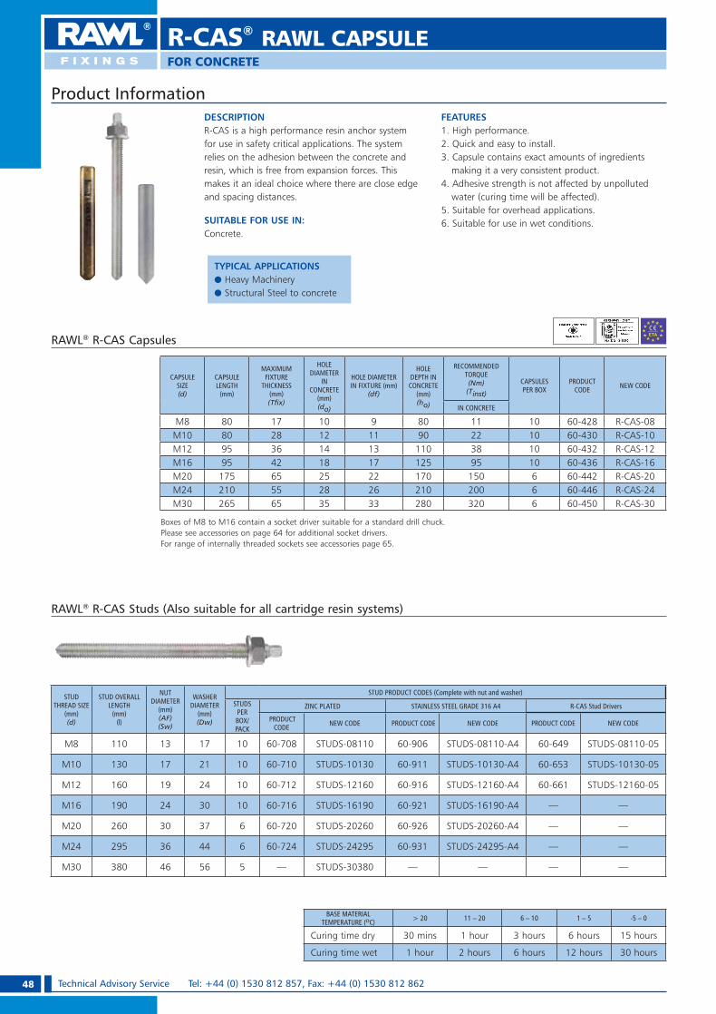
48 Technical Advisory Service Tel: +44 (0) 1530 812 857, Fax: +44 (0) 1530 812 862
DESCRIPTIONR-CAS is a high performance resin anchor system for use in safety critical applications. The system relies on the adhesion between the concrete and resin, which is free from expansion forces. This makes it an ideal choice where there are close edge and spacing distances.
SUITABLE FOR USE IN:Concrete.
FEATURES1. High performance.2. Quick and easy to install.3. Capsule contains exact amounts of ingredients
making it a very consistent product.4. Adhesive strength is not affected by unpolluted
water (curing time will be affected).5. Suitable for overhead applications.6. Suitable for use in wet conditions.
Product Information
RAWL® R-CAS Studs (Also suitable for all cartridge resin systems)
BASE MATERIAL TEMPERATURE (oC) > 20 11 – 20 6 – 10 1 – 5 -5 – 0
Curing time dry 30 mins 1 hour 3 hours 6 hours 15 hours
Curing time wet 1 hour 2 hours 6 hours 12 hours 30 hours
STUDTHREAD SIZE
(mm) (d)
STUD OVERALL LENGTH
(mm)(l)
NUTDIAMETER
(mm)(AF)(Sw)
WASHER DIAMETER
(mm) (Dw)
STUD PRODUCT CODES (Complete with nut and washer)
STUDSPER BOX/PACK
ZINC PLATED STAINLESS STEEL GRADE 316 A4 R-CAS Stud Drivers
PRODUCT CODE NEW CODE PRODUCT CODE NEW CODE PRODUCT CODE NEW CODE
M8 110 13 17 10 60-708 STUDS-08110 60-906 STUDS-08110-A4 60-649 STUDS-08110-05
M10 130 17 21 10 60-710 STUDS-10130 60-911 STUDS-10130-A4 60-653 STUDS-10130-05
M12 160 19 24 10 60-712 STUDS-12160 60-916 STUDS-12160-A4 60-661 STUDS-12160-05
M16 190 24 30 10 60-716 STUDS-16190 60-921 STUDS-16190-A4 — —
M20 260 30 37 6 60-720 STUDS-20260 60-926 STUDS-20260-A4 — —
M24 295 36 44 6 60-724 STUDS-24295 60-931 STUDS-24295-A4 — —
M30 380 46 56 5 — STUDS-30380 — — — —
RAWL® R-CAS Capsules
Boxes of M8 to M16 contain a socket driver suitable for a standard drill chuck. Please see accessories on page 64 for additional socket drivers.For range of internally threaded sockets see accessories page 65.
CAPSULE SIZE (d)
CAPSULE LENGTH
(mm)
MAXIMUM FIXTURE
THICKNESS (mm) (T� x)
HOLE DIAMETER
IN CONCRETE
(mm)(do)
HOLE DIAMETER IN FIXTURE (mm)
(df)
HOLE DEPTH IN CONCRETE
(mm)(ho)
RECOMMENDED TORQUE (Nm)
(Tinst)
CAPSULES PER BOX
PRODUCT CODE NEW CODE
IN CONCRETE
M8 80 17 10 9 80 11 10 60-428 R-CAS-08M10 80 28 12 11 90 22 10 60-430 R-CAS-10M12 95 36 14 13 110 38 10 60-432 R-CAS-12M16 95 42 18 17 125 95 10 60-436 R-CAS-16M20 175 65 25 22 170 150 6 60-442 R-CAS-20M24 210 55 28 26 210 200 6 60-446 R-CAS-24M30 265 65 35 33 280 320 6 60-450 R-CAS-30
R-CAS® RAWL CAPSULE
FOR CONCRETE
TYPICAL APPLICATIONSe Heavy Machinerye Structural Steel to concrete
RAWL_KATALOG_2007_2008.indb 48RAWL_KATALOG_2007_2008.indb 48 2007-10-15 14:35:262007-10-15 14:35:26

49Technical Advisory Service e-mail: [email protected] OR [email protected]
Installation
1. Drill correct diameter and depth of hole for the stud or socket.
2. Clean the hole using brush and air three times.
3. Insert R-CAS capsule into the hole. Connect stud or socket to drilling machine using the appropriate driver system.
4. Offer stud or socket up to capsule and switch on machine. Drive stud or socket into capsule. To prevent over mixing, stop as soon as bottom of hole is reached. Leave undisturbed until resin has set.
5. Position fixture and tighten to recommended torque.
RAWL® R-CAS Performance Data
SIZE
CONCRETE, fck,cube = 30N/mm2 (C20/25)
CHARACTERISTIC RESISTANCE (kN)
DESIGN RESISTANCE (Factored) (kN)
RECOMMENDED LOAD (Unfactored) (kN)
CHARACTERISTIC EDGE DISTANCE (mm)
CHARACTERISTIC SPACING
(mm)
TENSION (NRk)
SHEAR(VRk)
TENSION (NRd)
SHEAR (VRd)
TENSION (Nrec)
SHEAR (Vrec)
TENSION (Ccr,N)
SHEAR(Ccr,V)
TENSION & SHEAR(Scr,N) (Scr,V)
M8 15.4 9.9 8.3 7.9 5.9 5.7 100 130 130
M10 23.8 15.7 11.3 12.6 8.1 9.0 130 150 150
M12 35.1 22.9 15.9 18.3 11.4 13.1 150 170 170
M16 64.4 42.5 28.0 34.0 20.0 24.3 170 190 190
M20 103.9 66.8 43.3 53.4 30.9 38.2 220 220 220
M24 138.3 95.7 55.3 76.6 39.5 54.7 260 260 260
M30 213.9 152.5 85.5 122.0 61.1 87.1 340 340 340
For further explanations on calculations please see pages 10 and 11
Edge Distance (Concrete Only)
EDGE (mm)
TENSILE: EDGE REDUCTION FACTORS SHEAR: EDGE REDUCTION FACTORS
M8 M10 M12 M16 M20 M24 M30 M8 M10 M12 M16 M20 M24 M30
60 0.76 0.5070 0.82 0.75 0.58 0.5080 0.88 0.80 0.74 0.66 0.57 0.5090 0.94 0.85 0.78 0.75 0.64 0.56100 1.0 0.90 0.83 0.77 0.83 0.71 0.62 0.52110 0.95 0.87 0.81 0.92 0.78 0.69 0.58 0.50130 1.0 0.96 0.89 0.77 1.0 0.93 0.81 0.68 0.59 0.50150 1.0 0.96 0.83 0.76 1.0 0.94 0.79 0.68 0.57170 1.0 0.88 0.81 1.0 0.89 0.77 0.65 0.50190 0.94 0.86 0.75 1.0 0.86 0.73 0.56220 1.0 0.93 0.80 1.0 0.85 0.65260 1.0 0.88 1.0 0.76300 0.92 0.88340 1.0 1.0
Spacing (Concrete Only)
SPACING(mm)
TENSILE & SHEAR REDUCTION FACTORS
M8 M10 M12 M16 M20 M24 M30
60 0.8070 0.83 0.8080 0.87 0.83 0.8090 0.90 0.86 0.83100 0.93 0.89 0.85 0.81110 0.97 0.91 0.87 0.83 0.80130 1.0 0.97 0.92 0.87 0.84 0.80150 1.0 0.97 0.92 0.87 0.83170 1.0 0.96 0.91 0.86 0.80190 1.0 0.95 0.89 0.82220 1.0 0.94 0.85260 1.0 0.90300 0.95340 1.0
Reduction Factors – Edge and Spacing Distances.The full characteristic edge and spacing distances shown in the table above are the minimum allowable for the quoted DESIGN RESISTANCE or RECOMMENDED LOAD, depending on your design method.Where these dimensions are not achievable, the appropriate reduction factor/s from the tables below must be applied to the DESIGN RESISTANCE or RECOMMENDED LOAD. Choose the required bolt diameter across the
top of the appropriate table and read down the left hand column until actual edge or spacing distance is found. Read off the reduction factor where the two lines intersect (interpolate as required). Multiply this factor by the DESIGN RESISTANCE or RECOMMENDED LOAD quoted in the table. On the occasion that multiple close edge and/or spacing distances occur, the appropriate reduction factors must be applied.
Speci� cation Data
R-CAS® RAWL CAPSULE
FOR CONCRETE
RAWL_KATALOG_2007_2008.indb 49RAWL_KATALOG_2007_2008.indb 49 2007-10-15 14:35:382007-10-15 14:35:38

50 Technical Advisory Service Tel: +44 (0) 1530 812 857, Fax: +44 (0) 1530 812 862
R-HAC® RAWL CAPSULE
DESCRIPTIONR-HAC capsule range is a high performance fixing system that offers a quick and simple method of fixing either threaded studs or rebar into solid concrete.Simply installed by hammering the stud or rebar through the capsule using a hammer or mechanical drill.Not suitable for overhead applications.
SUITABLE FOR USE IN:Concrete.
FEATURES1. High performance. 2. Quick and easy to install.3. No expensive tooling required for installation.4. Long shelf life.5. Double capsules can be used for deep
embedment.6. Ideal for starter bar applications.
Installation
1. Drill appropriate hole for anchor taking care to achieve the exact hole depth.
5. Pour new concrete.4. The rebar is simply hammered through the capsule using a manual hammer (M8 - M12) or mechanical hammer (M16 - M30). Leave undisturbed until resin has set.
3. Insert capsule(s).2. Clean the hole using brush and air three times.
RAWL® R-HAC (Studding)
CAPSULE DIAMETER
(mm)
CAPSULE LENGTH
(mm)
HOLE DIAMETER
IN CONCRETE(mm)(do)
HOLE DIAMETER IN FIXTURE
(mm)(df)
HOLE DEPTHIN CONCRETE
(mm)(ho)
RECOMMENDED TORQUE(Nm)
(Tinst)
CAPSULES PER BOX/PACK
CAPSULES CODES
PRODUCT CODE NEW CODE
M8 85 10 9 85 6 10 60-600 R-HAC-08M10 85 12 11 85 12 10 60-601 R-HAC-10M12 95 14 13 110 20 10 60-602 R-HAC-12M16 95 18 17 140 45 10 60-603 R-HAC-16M20 140 25 22 180 100 6 60-604 R-HAC-20M24 215 28 26 210 150 6 60-605 R-HAC-24M30 270 35 32 265 300 6 60-606 R-HAC-30
Rebar
CAPSULE TYPE
REBAR NOMINAL DIAMETER
(mm)(d)
ACTUAL DIAMETER
(mm)(df)
HOLE DIAMETER IN CONCRETE
(mm) (do)
HOLEDEPTH(mm)(ho)
NUMBER OF
CAPSULES
HOLE DEPTH (mm)(ho)
NUMBER OF CAPSULES
PRODUCT CODE
PRODUCT CODE NEW CODE
M10 10 11.5 13 85 1 170 2 60-601 R-HAC-10M12 12 13.9 15 110 1 220 2 60-602 R-HAC-12M16 16 18.7 20 140 1 280 2 60-603 R-HAC-16M20 20 23.4 25 180 1 360 2 60-604 R-HAC-20M24 25 29.2 30 210 1 420 2 60-605 R-HAC-24M30 32 37.4 38 265 1 530 2 60-606 R-HAC-30
BASE MATERIAL TEMPERATURE (°C) > 20 11 – 20 1 – 10 -5 – 0
Curing time 1 hour 2 hours 5 hours 10 hours
If you are bonding rebar into reinforced concrete, where the size, position etc. of the reinforcing is known, then design principles contained within Eurocode 2 can be adopted instead of the design recommendations contained within this manual.
Product Information
FOR CONCRETE
TYPICAL APPLICATIONSe Starter Bar (Rebar)e Studding
RAWL_KATALOG_2007_2008.indb 50RAWL_KATALOG_2007_2008.indb 50 2007-10-15 14:35:402007-10-15 14:35:40

51Technical Advisory Service e-mail: [email protected] OR [email protected]
R-HAC® RAWL CAPSULE
Reduction Factors – Edge and Spacing Distances.The full characteristic edge and spacing distances shown in the table above are the minimum allowable for the quoted DESIGN RESISTANCE or RECOMMENDED LOAD, depending on your design method.Where these dimensions are not achievable, the appropriate reduction factor/s from the tables below must be applied to the DESIGN RESISTANCE or RECOMMENDED LOAD. Choose the required bolt diameter across the
top of the appropriate table and read down the left hand column until actual edge or spacing distance is found. Read off the reduction factor where the two lines intersect (interpolate as required). Multiply this factor by the DESIGN RESISTANCE or RECOMMENDED LOAD quoted in the table. On the occasion that multiple close edge and/or spacing distances occur, the appropriate reduction factors must be applied.
RAWL® R-HAC Performance Data
SIZE
CONCRETE, fck,cube = 30N/mm2 (C20/25)
CHARACTERISTIC RESISTANCE(kN)
DESIGN RESISTANCE (Factored)
(kN)
RECOMMENDED LOAD (Unfactored)
(kN)
CHARACTERISTIC EDGE DISTANCE(mm)
CHARACTERISTIC SPACING
(mm)
TENSION(NRk)
SHEAR(VRk)
TENSION(NRd)
SHEAR(VRd)
TENSION(Nrec)
SHEAR(Vrec)
TENSION(Ccr,N)
SHEAR(Ccr,V)
TENSION & SHEAR(Scr,N) (Scr,V)
M8 12.3 9.9 6.1 7.9 4.4 5.7 80 100 100
M10 19.4 15.7 9.7 12.6 6.9 9.0 90 130 130
M12 29.2 22.9 13.9 18.3 9.9 13.1 110 150 150
M16 51.2 42.5 23.3 34.0 16.6 24.3 130 170 170
M20 76.8 66.8 33.4 53.4 23.9 38.2 150 190 210
M24 94.6 95.7 39.4 76.6 28.1 54.7 190 240 240
M30 119.6 153.3 47.9 122.6 34.2 87.6 240 280 280
Edge Distance (Concrete Only)
EDGE(mm)
TENSILE : EDGE REDUCTION FACTORS SHEAR : EDGE REDUCTION FACTORS
M8 M10 M12 M16 M20 M24 M30 M8 M10 M12 M16 M20 M24 M30
50 0.77 0.5060 0.85 0.80 0.60 0.5070 0.92 0.87 0.78 0.70 0.58 0.5080 1.00 0.93 0.84 0.80 0.66 0.5790 1.00 0.89 0.82 0.90 0.75 0.64 0.56100 0.95 0.86 0.80 1.00 0.83 0.71 0.62 0.56110 1.00 0.91 0.84 0.77 0.92 0.78 0.69 0.61 0.50130 1.00 0.92 0.83 1.00 0.92 0.81 0.72 0.59150 1.00 0.90 0.82 1.00 0.94 0.83 0.68 0.50170 0.97 0.86 1.00 0.94 0.77 0.58190 1.00 0.90 1.00 0.86 0.65210 0.94 0.95 0.73240 1.00 1.00 0.85280 1.00
Spacing (Concrete Only)
SPACING(mm)
TENSILE & SHEAR REDUCTION FACTORS
M8 M10 M12 M16 M20 M24 M30
50 0.8060 0.84 0.8070 0.88 0.83 0.8080 0.92 0.87 0.8390 0.96 0.90 0.86 0.81100 1.00 0.93 0.88 0.84 0.80110 0.97 0.91 0.86 0.82 0.79130 1.00 0.97 0.91 0.86 0.82 0.80150 1.00 0.95 0.90 0.85 0.83170 1.00 0.94 0.88 0.85190 0.98 0.92 0.88210 1.00 0.95 0.91240 1.00 0.95280 1.00
Speci� cation Data
For further explanations on calculations please see pages 10 and 11
Performance is based on single capsule embedment.
FOR CONCRETE
RAWL_KATALOG_2007_2008.indb 51RAWL_KATALOG_2007_2008.indb 51 2007-10-15 14:35:422007-10-15 14:35:42
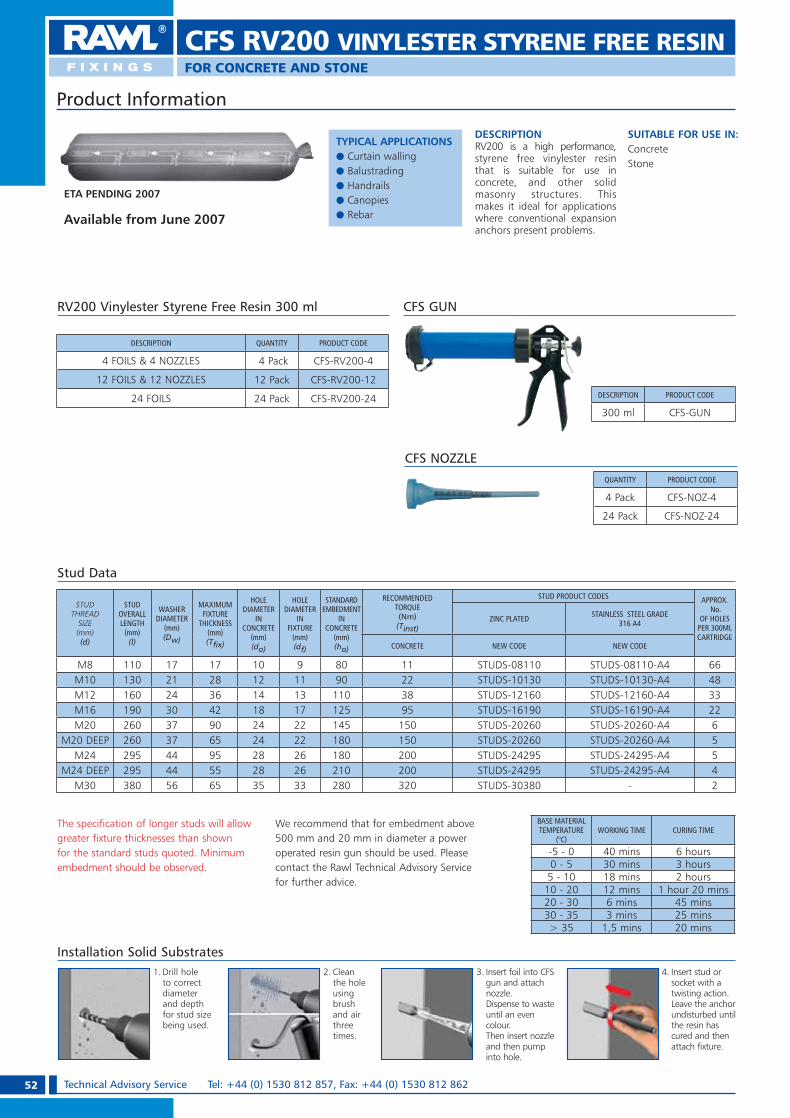
52 Technical Advisory Service Tel: +44 (0) 1530 812 857, Fax: +44 (0) 1530 812 862
CFS RV200 VINYLESTER STYRENE FREE RESINFOR CONCRETE AND STONE
The specification of longer studs will allow greater fixture thicknesses than shown for the standard studs quoted. Minimum embedment should be observed.
We recommend that for embedment above 500 mm and 20 mm in diameter a power operated resin gun should be used. Please contact the Rawl Technical Advisory Service for further advice.
Stud Data
TYPICAL APPLICATIONSe Curtain wallinge Balustradinge Handrailse Canopiese Rebar
Product Information
STUD THREAD
SIZE (mm) (d)
STUD OVERALL LENGTH
(mm) (l)
WASHER DIAMETER
(mm)(Dw)
MAXIMUM FIXTURE
THICKNESS (mm) (T� x)
HOLE DIAMETER
IN CONCRETE
(mm)(do)
HOLE DIAMETER
IN FIXTURE
(mm) (df)
STANDARD EMBEDMENT
IN CONCRETE
(mm)(ho)
RECOMMENDED TORQUE (Nm)(Tinst)
STUD PRODUCT CODES APPROX. No.
OF HOLES PER 300ML CARTRIDGE
ZINC PLATED STAINLESS STEEL GRADE 316 A4
CONCRETE NEW CODE NEW CODE
M8 110 17 17 10 9 80 11 STUDS-08110 STUDS-08110-A4 66M10 130 21 28 12 11 90 22 STUDS-10130 STUDS-10130-A4 48M12 160 24 36 14 13 110 38 STUDS-12160 STUDS-12160-A4 33M16 190 30 42 18 17 125 95 STUDS-16190 STUDS-16190-A4 22M20 260 37 90 24 22 145 150 STUDS-20260 STUDS-20260-A4 6
M20 DEEP 260 37 65 24 22 180 150 STUDS-20260 STUDS-20260-A4 5M24 295 44 95 28 26 180 200 STUDS-24295 STUDS-24295-A4 5
M24 DEEP 295 44 55 28 26 210 200 STUDS-24295 STUDS-24295-A4 4M30 380 56 65 35 33 280 320 STUDS-30380 - 2
DESCRIPTION QUANTITY PRODUCT CODE
4 FOILS & 4 NOZZLES 4 Pack CFS-RV200-4
12 FOILS & 12 NOZZLES 12 Pack CFS-RV200-12
24 FOILS 24 Pack CFS-RV200-24
RV200 Vinylester Styrene Free Resin 300 ml
QUANTITY PRODUCT CODE
4 Pack CFS-NOZ-4
24 Pack CFS-NOZ-24
CFS NOZZLE
DESCRIPTION PRODUCT CODE
300 ml CFS-GUN
CFS GUN
DESCRIPTIONRV200 is a high performance, styrene free vinylester resin that is suitable for use in concrete, and other solid masonry structures. This makes it ideal for applications where conventional expansion anchors present problems.
SUITABLE FOR USE IN:ConcreteStone
ETA PENDING 2007
Installation Solid Substrates1. Drill hole
to correct diameter and depth for stud size being used.
2. Clean the hole using brush and air three times.
3. Insert foil into CFS gun and attach nozzle.Dispense to waste until an even colour. Then insert nozzle and then pump into hole.
4. Insert stud or socket with a twisting action. Leave the anchor undisturbed until the resin has cured and then attach fixture.
Available from June 2007
BASE MATERIAL TEMPERATURE
(°C)WORKING TIME CURING TIME
-5 - 0 40 mins 6 hours0 - 5 30 mins 3 hours5 - 10 18 mins 2 hours10 - 20 12 mins 1 hour 20 mins20 - 30 6 mins 45 mins30 - 35 3 mins 25 mins> 35 1,5 mins 20 mins
RAWL_KATALOG_2007_2008.indb 52RAWL_KATALOG_2007_2008.indb 52 2007-10-15 14:35:432007-10-15 14:35:43
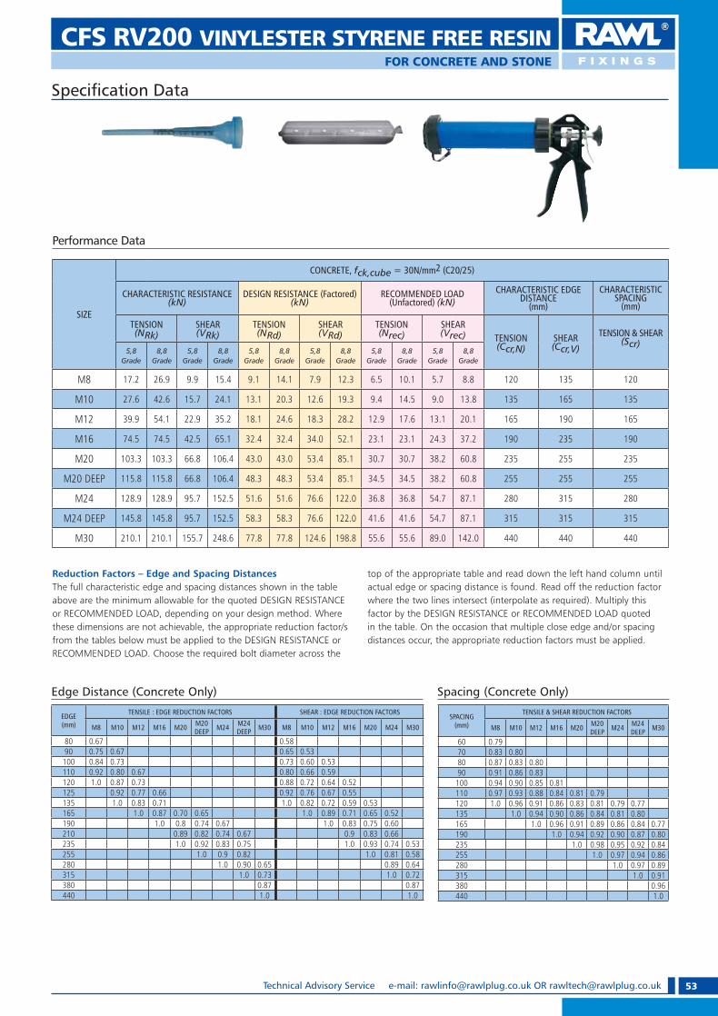
53Technical Advisory Service e-mail: [email protected] OR [email protected]
CFS RV200 VINYLESTER STYRENE FREE RESINFOR CONCRETE AND STONE
Reduction Factors – Edge and Spacing DistancesThe full characteristic edge and spacing distances shown in the table above are the minimum allowable for the quoted DESIGN RESISTANCE or RECOMMENDED LOAD, depending on your design method. Where these dimensions are not achievable, the appropriate reduction factor/s from the tables below must be applied to the DESIGN RESISTANCE or RECOMMENDED LOAD. Choose the required bolt diameter across the
top of the appropriate table and read down the left hand column until actual edge or spacing distance is found. Read off the reduction factor where the two lines intersect (interpolate as required). Multiply this factor by the DESIGN RESISTANCE or RECOMMENDED LOAD quoted in the table. On the occasion that multiple close edge and/or spacing distances occur, the appropriate reduction factors must be applied.
Performance Data
Speci� cation Data
SIZE
CONCRETE, fck,cube = 30N/mm2 (C20/25)
CHARACTERISTIC RESISTANCE(kN)
DESIGN RESISTANCE (Factored) (kN)
RECOMMENDED LOAD (Unfactored) (kN)
CHARACTERISTIC EDGE DISTANCE
(mm)
CHARACTERISTIC SPACING
(mm)
TENSION(NRk)
SHEAR(VRk)
TENSION(NRd)
SHEAR(VRd)
TENSION(Nrec)
SHEAR(Vrec) TENSION
(Ccr,N)SHEAR(Ccr,V)
TENSION & SHEAR(Scr)
5,8Grade
8,8Grade
5,8Grade
8,8Grade
5,8Grade
8,8Grade
5,8Grade
8,8Grade
5,8Grade
8,8Grade
5,8Grade
8,8Grade
M8 17.2 26.9 9.9 15.4 9.1 14.1 7.9 12.3 6.5 10.1 5.7 8.8 120 135 120
M10 27.6 42.6 15.7 24.1 13.1 20.3 12.6 19.3 9.4 14.5 9.0 13.8 135 165 135
M12 39.9 54.1 22.9 35.2 18.1 24.6 18.3 28.2 12.9 17.6 13.1 20.1 165 190 165
M16 74.5 74.5 42.5 65.1 32.4 32.4 34.0 52.1 23.1 23.1 24.3 37.2 190 235 190
M20 103.3 103.3 66.8 106.4 43.0 43.0 53.4 85.1 30.7 30.7 38.2 60.8 235 255 235
M20 DEEP 115.8 115.8 66.8 106.4 48.3 48.3 53.4 85.1 34.5 34.5 38.2 60.8 255 255 255
M24 128.9 128.9 95.7 152.5 51.6 51.6 76.6 122.0 36.8 36.8 54.7 87.1 280 315 280
M24 DEEP 145.8 145.8 95.7 152.5 58.3 58.3 76.6 122.0 41.6 41.6 54.7 87.1 315 315 315
M30 210.1 210.1 155.7 248.6 77.8 77.8 124.6 198.8 55.6 55.6 89.0 142.0 440 440 440
SPACING(mm)
TENSILE & SHEAR REDUCTION FACTORS
M8 M10 M12 M16 M20 M20 DEEP M24 M24
DEEP M30
60 0.7970 0.83 0.8080 0.87 0.83 0.8090 0.91 0.86 0.83100 0.94 0.90 0.85 0.81110 0.97 0.93 0.88 0.84 0.81 0.79120 1.0 0.96 0.91 0.86 0.83 0.81 0.79 0.77135 1.0 0.94 0.90 0.86 0.84 0.81 0.80165 1.0 0.96 0.91 0.89 0.86 0.84 0.77190 1.0 0.94 0.92 0.90 0.87 0.80235 1.0 0.98 0.95 0.92 0.84255 1.0 0.97 0.94 0.86280 1.0 0.97 0.89315 1.0 0.91380 0.96440 1.0
Edge Distance (Concrete Only) Spacing (Concrete Only)
EDGE(mm)
TENSILE : EDGE REDUCTION FACTORS SHEAR : EDGE REDUCTION FACTORS
M8 M10 M12 M16 M20 M20 DEEP M24 M24
DEEP M30 M8 M10 M12 M16 M20 M24 M30
80 0.67 0.5890 0.75 0.67 0.65 0.53100 0.84 0.73 0.73 0.60 0.53110 0.92 0.80 0.67 0.80 0.66 0.59120 1.0 0.87 0.73 0.88 0.72 0.64 0.52125 0.92 0.77 0.66 0.92 0.76 0.67 0.55135 1.0 0.83 0.71 1.0 0.82 0.72 0.59 0.53165 1.0 0.87 0.70 0.65 1.0 0.89 0.71 0.65 0.52190 1.0 0.8 0.74 0.67 1.0 0.83 0.75 0.60210 0.89 0.82 0.74 0.67 0.9 0.83 0.66235 1.0 0.92 0.83 0.75 1.0 0.93 0.74 0.53255 1.0 0.9 0.82 1.0 0.81 0.58280 1.0 0.90 0.65 0.89 0.64315 1.0 0.73 1.0 0.72380 0.87 0.87440 1.0 1.0
RAWL_KATALOG_2007_2008.indb 53RAWL_KATALOG_2007_2008.indb 53 2007-10-15 14:35:522007-10-15 14:35:52

54 Technical Advisory Service Tel: +44 (0) 1530 812 857, Fax: +44 (0) 1530 812 862
CFS RM50 POLYESTER STYRENE FREE RESINFOR CONCRETE, BRICK, BLOCK AND STONE
The specification of longer studs will allow greater fixture thicknesses than shown for the standard studs quoted. Minimum embedment should be observed.
For embedment above 500 mm and diameters above M20 please consult the Rawlplug Technical Advisory Service.
Stud Data
BASE MATERIAL TEMPERATURE
(°C)WORKING TIME CURING TIME
30 3 mins 25 mins20 7 mins 50 mins10 22 mins 1 hour 30 mins5 30 mins 3 hours 20 mins
Product Information
STUD THREAD SIZE (mm) (d)
STUD OVERALL LENGTH
(mm) (l)
WASHER DIAMETER
(mm)(Dw)
MAXIMUM FIXTURE
THICKNESS (mm) (T� x)
HOLE DIAMETER
IN CONCRETE
(mm)(do)
HOLE DIAMETER
IN FIXTURE
(mm) (df)
Standard embedment
IN CONCRETE
(mm)(ho)
RECOMMENDED TORQUE (Nm)
(Tinst)
STUD PRODUCT CODES APPROX No.
OF HOLES PER 300ML CARTRIDGE
ZINC PLATED
STAINLESS STEEL GRADE 316 A4
CONCRETE BRICKWORK PRODUCT CODE NEW CODE PRODUCT
CODE NEW CODE
M8 110 17 17 10 9 80 11 2 60-708 STUDS-08110 60-906 STUDS-08110-A4 66M10 130 21 28 12 11 90 22 6 60-710 STUDS-10130 60-911 STUDS-10130-A4 48M12 160 24 36 14 13 110 38 11 60-712 STUDS-12160 60-916 STUDS-12160-A4 33M16 190 30 42 18 17 125 95 24 60-716 STUDS-16190 60-921 STUDS-16190-A4 22M20 260 37 90 24 22 145 150 - 60-720 STUDS-20260 60-926 STUDS-20260-A4 6
M20 DEEP 260 37 55 24 22 180 150 - 60-720 STUDS-20260 60-926 STUDS-20260-A4 5M24 295 44 85 28 26 180 200 - 60-724 STUDS-24295 60-931 STUDS-24295-A4 5
M24 DEEP 295 44 55 28 26 210 200 - 60-724 STUDS-24295 60-931 STUD-24295-A4 4
Note: For perforated brickwork and hollow block work a mesh sleeve must be inserted into the hole prior to the resin being pumped.
RM50 Polyester Styrene Free Resin 300 ml
QUANTITY PRODUCT CODE
4 Pack CFS-NOZ-4
24 Pack CFS-NOZ-24
CFS NOZZLE
DESCRIPTION PRODUCT CODE
300 ml CFS-GUN
CFS GUN
DESCRIPTIONRM50 is a high performance, styrene free resin that is suitable for use in concrete, and other solid or hollow masonry structures. This makes it ideal for applications where conventional expansion anchors are not appropria-te.
SUITABLE FOR USE IN:ConcreteBrickworkBlockworkStone
Installation Solid Substrates
Installation Hollow Substrates & Substrates with Voids
1. Drill hole to correct diameter and depth for stud size being used.
2. Clean the hole using brush and air three times.
3. Insert foil into CFS gun and attach nozzle.Dispense to waste until an even colour. Then insert nozzle and pump into hole.
4. Insert stud or socket with a twisting action. Leave the anchor undisturbed until the resin has cured and then attach fixture.
1. Drill hole to correct diameter and depth for mesh sleeve being used.
2. Insert sleeve into hole.
3. Insert foil into CFS gun and attach nozzle.Dispense to waste until an even colour. Then insert nozzle and pump to fill sleeve.
4. Insert stud or socket with a twisting action. Leave the anchor undisturbed until the resin has cured and then attach fixture.
DESCRIPTION QUANTITY PRODUCT CODE
4 FOILS & 4 NOZZLES 4 Pack CFS-RM50-4
12 FOILS & 12 NOZZLES 12 Pack CFS-RM50-12
24 FOILS 24 Pack CFS-RM50-24
TYPICAL APPLICATIONSe Curtain wallinge Balustradinge Handrailse Canopiese Rebar
RAWL_KATALOG_2007_2008.indb 54RAWL_KATALOG_2007_2008.indb 54 2007-10-15 14:36:002007-10-15 14:36:00
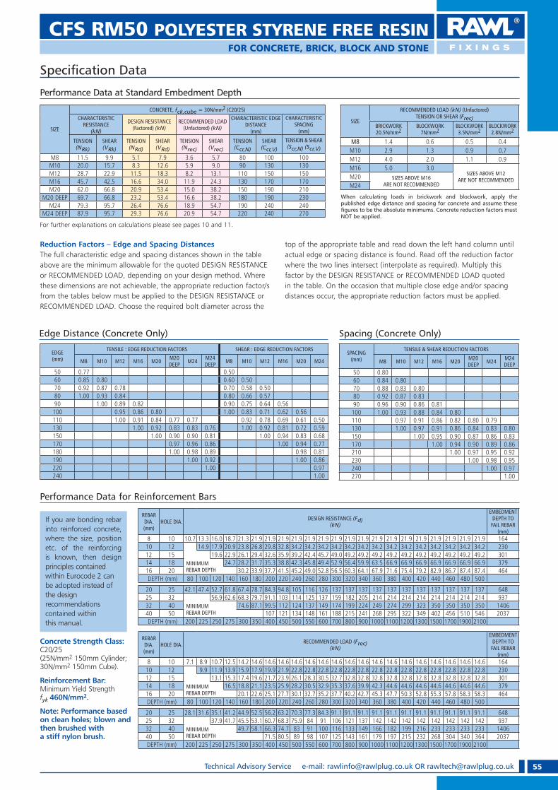
55Technical Advisory Service e-mail: [email protected] OR [email protected]
CFS RM50 POLYESTER STYRENE FREE RESINFOR CONCRETE, BRICK, BLOCK AND STONE
Reduction Factors – Edge and Spacing DistancesThe full characteristic edge and spacing distances shown in the table above are the minimum allowable for the quoted DESIGN RESISTANCE or RECOMMENDED LOAD, depending on your design method. Where these dimensions are not achievable, the appropriate reduction factor/s from the tables below must be applied to the DESIGN RESISTANCE or RECOMMENDED LOAD. Choose the required bolt diameter across the
top of the appropriate table and read down the left hand column until actual edge or spacing distance is found. Read off the reduction factor where the two lines intersect (interpolate as required). Multiply this factor by the DESIGN RESISTANCE or RECOMMENDED LOAD quoted in the table. On the occasion that multiple close edge and/or spacing distances occur, the appropriate reduction factors must be applied.
Performance Data for Reinforcement Bars
Performance Data at Standard Embedment Depth
Speci� cation Data
SIZE
RECOMMENDED LOAD (kN) (Unfactored)TENSION OR SHEAR (Frec)
BRICKWORK 20.5N/mm2
BLOCKWORK 7N/mm2
BLOCKWORK 3.5N/mm2
BLOCKWORK 2.8N/mm2
M8 1.4 0.6 0.5 0.4M10 2.9 1.3 0.9 0.7M12 4.0 2.0 1.1 0.9M16 5.0 3.0
SIZES ABOVE M12 ARE NOT RECOMMENDEDM20 SIZES ABOVE M16
ARE NOT RECOMMENDEDM24
SIZE
CONCRETE, fck,cube = 30N/mm2 (C20/25)CHARACTERISTIC
RESISTANCE(kN)
DESIGN RESISTANCE (Factored) (kN)
RECOMMENDED LOAD (Unfactored) (kN)
CHARACTERISTIC EDGE DISTANCE
(mm)
CHARACTERISTIC SPACING
(mm)
TENSION(NRk)
SHEAR(VRk)
TENSION(NRd)
SHEAR(VRd)
TENSION(Nrec)
SHEAR(Vrec)
TENSION(Ccr,N)
SHEAR(Ccr,V)
TENSION & SHEAR(Scr,N) (Scr,V)
M8 11.5 9.9 5.1 7.9 3.6 5.7 80 100 100M10 20.0 15.7 8.3 12.6 5.9 9.0 90 130 130M12 28.7 22.9 11.5 18.3 8.2 13.1 110 150 150M16 45.7 42.5 16.6 34.0 11.9 24.3 130 170 170M20 62.0 66.8 20.9 53.4 15.0 38.2 150 190 210
M20 DEEP 69.7 66.8 23.2 53.4 16.6 38.2 180 190 230M24 79.3 95.7 26.4 76.6 18.9 54.7 190 240 240
M24 DEEP 87.9 95.7 29.3 76.6 20.9 54.7 220 240 270
For further explanations on calculations please see pages 10 and 11.
EDGE(mm)
TENSILE : EDGE REDUCTION FACTORS SHEAR : EDGE REDUCTION FACTORS
M8 M10 M12 M16 M20 M20 DEEP M24 M24
DEEP M8 M10 M12 M16 M20 M24
50 0.77 0.5060 0.85 0.80 0.60 0.5070 0.92 0.87 0.78 0.70 0.58 0.5080 1.00 0.93 0.84 0.80 0.66 0.5790 1.00 0.89 0.82 0.90 0.75 0.64 0.56100 0.95 0.86 0.80 1.00 0.83 0.71 0.62 0.56110 1.00 0.91 0.84 0.77 0.77 0.92 0.78 0.69 0.61 0.50130 1.00 0.92 0.83 0.83 0.76 1.00 0.92 0.81 0.72 0.59150 1.00 0.90 0.90 0.81 1.00 0.94 0.83 0.68170 0.97 0.96 0.86 1.00 0.94 0.77180 1.00 0.98 0.89 0.98 0.81190 1.00 0.92 1.00 0.86220 1.00 0.97240 1.00
SPACING(mm)
TENSILE & SHEAR REDUCTION FACTORS
M8 M10 M12 M16 M20 M20 DEEP M24 M24
DEEP50 0.8060 0.84 0.8070 0.88 0.83 0.8080 0.92 0.87 0.8390 0.96 0.90 0.86 0.81100 1.00 0.93 0.88 0.84 0.80110 0.97 0.91 0.86 0.82 0.80 0.79130 1.00 0.97 0.91 0.86 0.84 0.83 0.80150 1.00 0.95 0.90 0.87 0.86 0.83170 1.00 0.94 0.90 0.89 0.86210 1.00 0.97 0.95 0.92230 1.00 0.98 0.95240 1.00 0.97270 1.00
Edge Distance (Concrete Only) Spacing (Concrete Only)
Concrete Strength Class:C20/25 (25N/mm2 150mm Cylinder; 30N/mm2 150mm Cube).
Reinforcement Bar: Minimum Yield Strength fyk 460N/mm2.
Note: Performance based on clean holes; blown and then brushed with a stiff nylon brush.
If you are bonding rebar into reinforced concrete, where the size, position etc. of the reinforcing is known, then designprinciples containedwithin Eurocode 2 can be adopted instead of the design recommendationscontained within this manual.
REBAR DIA.(mm)
HOLE DIA. DESIGN RESISTANCE (Fd)(kN)
EMBEDMENT DEPTH TO
FAIL REBAR(mm)
8 10 10.7 13.3 16.0 18.7 21.3 21.9 21.9 21.9 21.9 21.9 21.9 21.9 21.9 21.9 21.9 21.9 21.9 21.9 21.9 21.9 21.9 21.9 16410 12 14.9 17.9 20.9 23.8 26.8 29.8 32.8 34.2 34.2 34.2 34.2 34.2 34.2 34.2 34.2 34.2 34.2 34.2 34.2 34.2 34.2 23012 15 19.6 22.9 26.1 29.4 32.6 35.9 39.2 42.4 45.7 49.0 49.2 49.2 49.2 49.2 49.2 49.2 49.2 49.2 49.2 49.2 30114 18 MINIMUM
REBAR DEPTH24.7 28.2 31.7 35.3 38.8 42.3 45.8 49.4 52.9 56.4 59.9 63.5 66.9 66.9 66.9 66.9 66.9 66.9 66.9 379
16 20 30.2 33.9 37.7 41.5 45.2 49.0 52.8 56.5 60.3 64.1 67.9 71.6 75.4 79.2 82.9 86.7 87.4 87.4 464 DEPTH (mm) 80 100 120 140 160 180 200 220 240 260 280 300 320 340 360 380 400 420 440 460 480 500
20 25 42.1 47.4 52.7 61.8 67.4 78.7 84.3 94.8 105 116 126 137 137 137 137 137 137 137 137 137 137 137 64825 32 56.9 62.6 68.3 79.7 91.1 103 114 125 137 159 182 205 214 214 214 214 214 214 214 214 93732 40 MINIMUM
REBAR DEPTH74.6 87.1 99.5 112 124 137 149 174 199 224 249 274 299 323 350 350 350 350 1406
40 50 107 121 134 148 161 188 215 241 268 295 322 349 402 456 510 546 2037 DEPTH (mm) 200 225 250 275 300 350 400 450 500 550 600 700 800 900 1000 1100 1200 1300 1500 1700 1900 2100
REBAR DIA.(mm)
HOLE DIA. RECOMMENDED LOAD (Frec)(kN)
EMBEDMENT DEPTH TO
FAIL REBAR(mm)
8 10 7.1 8.9 10.7 12.5 14.2 14.6 14.6 14.6 14.6 14.6 14.6 14.6 14.6 14.6 14.6 14.6 14.6 14.6 14.6 14.6 14.6 14.6 16410 12 9.9 11.9 13.9 15.9 17.9 19.9 21.9 22.8 22.8 22.8 22.8 22.8 22.8 22.8 22.8 22.8 22.8 22.8 22.8 22.8 22.8 23012 15 13.1 15.3 17.4 19.6 21.7 23.9 26.1 28.3 30.5 32.7 32.8 32.8 32.8 32.8 32.8 32.8 32.8 32.8 32.8 32.8 30114 18 MINIMUM
REBAR DEPTH16.5 18.8 21.1 23.5 25.9 28.2 30.5 32.9 35.3 37.6 39.9 42.3 44.6 44.6 44.6 44.6 44.6 44.6 44.6 379
16 20 20.1 22.6 25.1 27.7 30.1 32.7 35.2 37.7 40.2 42.7 45.3 47.7 50.3 52.8 55.3 57.8 58.3 58.3 464 DEPTH (mm) 80 100 120 140 160 180 200 220 240 260 280 300 320 340 360 380 400 420 440 460 480 500
20 25 28.1 31.6 35.1 41.2 44.9 52.5 56.2 63.2 70.3 77.3 84.3 91.1 91.1 91.1 91.1 91.1 91.1 91.1 91.1 91.1 91.1 91.1 64825 32 37.9 41.7 45.5 53.1 60.7 68.3 75.9 84 91 106 121 137 142 142 142 142 142 142 142 142 93732 40 MINIMUM
REBAR DEPTH49.7 58.1 66.3 74.7 83 91 100 116 133 149 166 182 199 216 233 233 233 233 1406
40 50 71.5 80.5 89 98 107 125 143 161 179 197 215 232 268 304 340 364 2037 DEPTH (mm) 200 225 250 275 300 350 400 450 500 550 600 700 800 900 1000 1100 1200 1300 1500 1700 1900 2100
When calculating loads in brickwork and blockwork, apply the published edge distance and spacing for concrete and assume these � gures to be the absolute minimums. Concrete reduction factors must NOT be applied.
RAWL_KATALOG_2007_2008.indb 55RAWL_KATALOG_2007_2008.indb 55 2007-10-15 14:36:132007-10-15 14:36:13
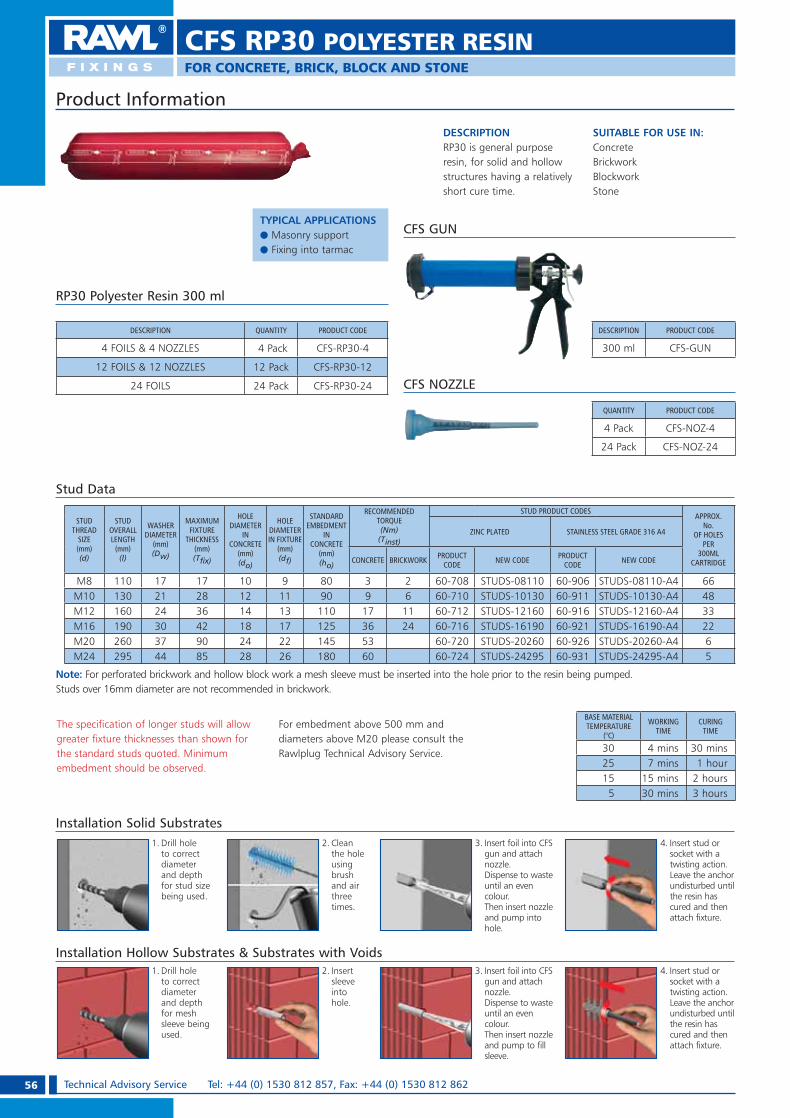
56 Technical Advisory Service Tel: +44 (0) 1530 812 857, Fax: +44 (0) 1530 812 862
CFS RP30 POLYESTER RESINFOR CONCRETE, BRICK, BLOCK AND STONE
The specification of longer studs will allow greater fixture thicknesses than shown for the standard studs quoted. Minimum embedment should be observed.
For embedment above 500 mm and diameters above M20 please consult the Rawlplug Technical Advisory Service.
DESCRIPTIONRP30 is general purpose resin, for solid and hollow structures having a relatively short cure time.
Stud Data
STUD THREAD
SIZE (mm) (d)
STUD OVERALL LENGTH
(mm) (l)
WASHER DIAMETER
(mm)(Dw)
MAXIMUM FIXTURE
THICKNESS (mm) (T� x)
HOLE DIAMETER
IN CONCRETE
(mm)(do)
HOLE DIAMETER IN FIXTURE
(mm) (df)
STANDARD EMBEDMENT
IN CONCRETE
(mm)(ho)
RECOMMENDED TORQUE (Nm)
(Tinst)
STUD PRODUCT CODESAPPROX.
No. OF HOLES
PER 300ML
CARTRIDGE
ZINC PLATED STAINLESS STEEL GRADE 316 A4
CONCRETE BRICKWORK PRODUCT CODE NEW CODE PRODUCT
CODE NEW CODE
M8 110 17 17 10 9 80 3 2 60-708 STUDS-08110 60-906 STUDS-08110-A4 66M10 130 21 28 12 11 90 9 6 60-710 STUDS-10130 60-911 STUDS-10130-A4 48M12 160 24 36 14 13 110 17 11 60-712 STUDS-12160 60-916 STUDS-12160-A4 33M16 190 30 42 18 17 125 36 24 60-716 STUDS-16190 60-921 STUDS-16190-A4 22M20 260 37 90 24 22 145 53 60-720 STUDS-20260 60-926 STUDS-20260-A4 6M24 295 44 85 28 26 180 60 60-724 STUDS-24295 60-931 STUDS-24295-A4 5
BASE MATERIAL TEMPERATURE
(°C)
WORKING TIME
CURING TIME
30 4 mins 30 mins25 7 mins 1 hour15 15 mins 2 hours
5 30 mins 3 hours
Note: For perforated brickwork and hollow block work a mesh sleeve must be inserted into the hole prior to the resin being pumped.Studs over 16mm diameter are not recommended in brickwork.
Product Information
SUITABLE FOR USE IN:ConcreteBrickworkBlockworkStone
RP30 Polyester Resin 300 ml
DESCRIPTION PRODUCT CODE
300 ml CFS-GUN
CFS GUN
QUANTITY PRODUCT CODE
4 Pack CFS-NOZ-4
24 Pack CFS-NOZ-24
CFS NOZZLE
Installation Solid Substrates
Installation Hollow Substrates & Substrates with Voids
1. Drill hole to correct diameter and depth for stud size being used.
2. Clean the hole using brush and air three times.
3. Insert foil into CFS gun and attach nozzle.Dispense to waste until an even colour. Then insert nozzle and pump into hole.
4. Insert stud or socket with a twisting action. Leave the anchor undisturbed until the resin has cured and then attach fixture.
1. Drill hole to correct diameter and depth for mesh sleeve being used.
2. Insert sleeve into hole.
3. Insert foil into CFS gun and attach nozzle.Dispense to waste until an even colour. Then insert nozzle and pump to fill sleeve.
4. Insert stud or socket with a twisting action. Leave the anchor undisturbed until the resin has cured and then attach fixture.
DESCRIPTION QUANTITY PRODUCT CODE
4 FOILS & 4 NOZZLES 4 Pack CFS-RP30-4
12 FOILS & 12 NOZZLES 12 Pack CFS-RP30-12
24 FOILS 24 Pack CFS-RP30-24
TYPICAL APPLICATIONSe Masonry supporte Fixing into tarmac
RAWL_KATALOG_2007_2008.indb 56RAWL_KATALOG_2007_2008.indb 56 2007-10-15 14:36:162007-10-15 14:36:16
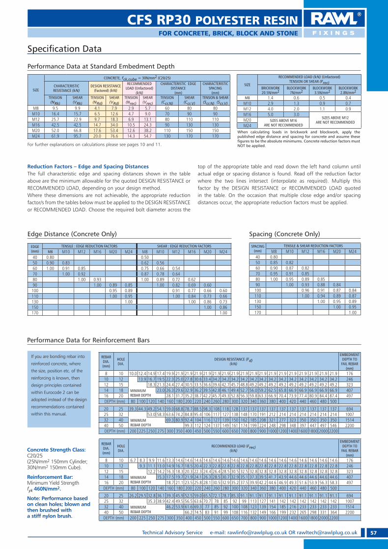
57Technical Advisory Service e-mail: [email protected] OR [email protected]
FOR CONCRETE, BRICK, BLOCK AND STONE
CFS RP30 POLYESTER RESIN
If you are bonding rebar into
reinforced concrete, where
the size, position etc. of the
reinforcing is known, then
design principles contained
within Eurocode 2 can be
adopted instead of the design
recommendations contained
within this manual.
Reduction Factors – Edge and Spacing DistancesThe full characteristic edge and spacing distances shown in the table above are the minimum allowable for the quoted DESIGN RESISTANCE or RECOMMENDED LOAD, depending on your design method. Where these dimensions are not achievable, the appropriate reduction factor/s from the tables below must be applied to the DESIGN RESISTANCE or RECOMMENDED LOAD. Choose the required bolt diameter across the
top of the appropriate table and read down the left hand column until actual edge or spacing distance is found. Read off the reduction factor where the two lines intersect (interpolate as required). Multiply this factor by the DESIGN RESISTANCE or RECOMMENDED LOAD quoted in the table. On the occasion that multiple close edge and/or spacing distances occur, the appropriate reduction factors must be applied.
Performance Data for Reinforcement Bars
Speci� cation Data
Performance Data at Standard Embedment Depth
SIZE
CONCRETE, fck,cube = 30N/mm2 (C20/25)
CHARACTERISTIC RESISTANCE (kN)
DESIGN RESISTANCE(Factored) (kN)
RECOMMENDED LOAD (Unfactored)
(kN)
CHARACTERISTIC EDGE DISTANCE
(mm)
CHARACTERISTIC SPACING
(mm)TENSION(NRk)
SHEAR(VRk)
TENSION (NRd)
SHEAR(VRd)
TENSION(Nrec)
SHEAR(Vrec)
TENSION (Ccr,N)
SHEAR(Ccr,V)
TENSION & SHEAR(Scr,N) (Scr,V)
M8 9.5 9.9 4.1 7.9 2.9 5.7 60 80 80M10 16.4 15.7 6.5 12.6 4.7 9.0 70 90 90M12 25.7 22.9 9.7 18.3 6.9 13.1 80 110 110M16 42.5 42.5 14.7 34.0 10.5 24.3 90 130 130M20 52.0 66.8 17.6 53.4 12.6 38.2 110 150 150M24 61.9 95.7 20.0 76.6 14.3 54.7 130 170 170
SIZE
RECOMMENDED LOAD (kN) (Unfactored)TENSION OR SHEAR (Frec)
BRICKWORK 20.5N/mm2
BLOCKWORK 7N/mm2
BLOCKWORK 3.5N/mm2
BLOCKWORK 2.8N/mm2
M8 1.4 0.6 0.5 0.4M10 2.9 1.3 0.9 0.7M12 4.0 2.0 1.1 0.9M16 5.0 3.0
SIZES ABOVE M12 ARE NOT RECOMMENDEDM20 SIZES ABOVE M16
ARE NOT RECOMMENDEDM24
Edge Distance (Concrete Only)
EDGE(mm)
TENSILE : EDGE REDUCTION FACTORS SHEAR : EDGE REDUCTION FACTORSM8 M10 M12 M16 M20 M24 M8 M10 M12 M16 M20 M24
40 0.80 0.5050 0.90 0.83 0.62 0.5660 1.00 0.91 0.85 0.75 0.66 0.5470 1.00 0.92 0.87 0.78 0.6480 1.00 0.93 1.00 0.89 0.72 0.6290 1.00 0.89 0.85 1.00 0.82 0.69 0.60100 0.95 0.89 0.91 0.77 0.66 0.60110 1.00 0.95 1.00 0.84 0.73 0.66130 1.00 1.00 0.86 0.73150 1.00 0.86170 1.00
Spacing (Concrete Only)
SPACING(mm)
TENSILE & SHEAR REDUCTION FACTORSM8 M10 M12 M16 M20 M24
40 0.8050 0.85 0.8260 0.90 0.87 0.8270 0.95 0.91 0.8580 1.00 0.95 0.89 0.8590 1.00 0.93 0.88 0.84100 0.96 0.91 0.87 0.84110 1.00 0.94 0.89 0.87130 1.00 0.95 0.89150 1.00 0.95170 1.00
For further explanations on calculations please see pages 10 and 11.
Concrete Strength Class:C20/25 (25N/mm2 150mm Cylinder; 30N/mm2 150mm Cube).
Reinforcement Bar: Minimum Yield Strength fyk 460N/mm2.
Note: Performance based on clean holes; blown and then brushed with a stiff nylon brush.
REBAR DIA.(mm)
HOLE DIA.
DESIGN RESISTANCE (Fd)(kN)
EMBEDMENT DEPTH TO
FAIL REBAR(mm)
8 10 10.0 12.4 14.9 17.4 19.9 21.9 21.9 21.9 21.9 21.9 21.9 21.9 21.9 21.9 21.9 21.9 21.9 21.9 21.9 21.9 21.9 21.9 17610 12 13.9 16.7 19.5 22.3 25.0 27.8 30.6 33.4 34.2 34.2 34.2 34.2 34.2 34.2 34.2 34.2 34.2 34.2 34.2 34.2 34.2 24612 15 18.3 21.3 24.4 27.4 30.5 33.5 36.6 39.6 42.7 45.7 48.8 49.2 49.2 49.2 49.2 49.2 49.2 49.2 49.2 49.2 32314 18 MINIMUM
REBAR DEPTH23.0 26.3 29.6 32.9 36.2 39.5 42.8 46.1 49.4 52.7 56.0 59.2 62.5 65.8 66.9 66.9 66.9 66.9 66.9 407
16 20 28.1 31.7 35.2 38.7 42.2 45.7 49.3 52.8 56.3 59.8 63.3 66.9 70.4 73.9 77.4 80.9 84.4 87.4 497 DEPTH (mm) 80 100 120 140 160 180 200 220 240 260 280 300 320 340 360 380 400 420 440 460 480 500
20 25 39.3 44.3 49.2 54.1 59.0 68.8 78.7 88.5 98.3 108 118 128 137 137 137 137 137 137 137 137 137 137 69425 32 53.0 58.3 63.6 74.2 84.8 95.4 106 117 127 138 148 170 191 212 214 214 214 214 214 214 100732 40 MINIMUM
REBAR DEPTH69.3 80.9 92.4 104 116 127 139 150 162 185 208 321 277 323 350 350 350 350 1514
40 50 99.3 112 124 137 149 161 174 199 224 248 298 348 397 447 497 546 2200 DEPTH (mm) 200 225 250 275 300 350 400 450 500 550 600 650 700 800 900 1000 1200 1400 1600 1800 2000 2200
REBAR DIA.(mm)
HOLE DIA.
RECOMMENDED LOAD (Frec)(kN)
EMBEDMENT DEPTH TO
FAIL REBAR(mm)
8 10 6.7 8.3 9.9 11.6 13.3 14.6 14.6 14.6 14.6 14.6 14.6 14.6 14.6 14.6 14.6 14.6 14.6 14.6 14.6 14.6 14.6 14.6 17610 12 9.3 11.1 13.0 14.9 16.7 18.5 20.4 22.3 22.8 22.8 22.8 22.8 22.8 22.8 22.8 22.8 22.8 22.8 22.8 22.8 22.8 24612 15 12.2 14.2 16.3 18.3 20.3 22.3 24.4 26.4 28.5 30.5 32.5 32.8 32.8 32.8 32.8 32.8 32.8 32.8 32.8 32.8 32314 18 MINIMUM
REBAR DEPTH15.3 17.5 19.7 21.9 24.1 26.3 28.5 30.7 32.9 35.1 37.3 39.5 41.7 43.9 44.6 44.6 44.6 44.6 44.6 407
16 20 18.7 21.1 23.5 25.8 28.1 30.5 32.9 35.2 37.5 39.9 42.2 44.6 46.9 49.3 51.6 53.9 56.3 58.3 497DEPTH (mm) 80 100 120 140 160 180 200 220 240 260 280 300 320 340 360 380 400 420 440 460 480 500
20 25 26.2 29.5 32.8 36.1 39.3 45.9 52.5 59.0 65.5 72.1 78.7 85.3 91.1 91.1 91.1 91.1 91.1 91.1 91.1 91.1 91.1 91.1 69425 32 35.3 38.9 42.4 49.5 56.5 63.6 70.7 78 85 92 99 113 127 141 142 142 142 142 142 142 100732 40 MINIMUM
REBAR DEPTH 46.2 53.9 61.6 69.3 77 85 92 100 108 123 139 154 185 216 233 233 233 233 1514
40 50 66.2 74.5 83 91 99 108 116 132 149 166 199 232 265 298 331 364 2200DEPTH (mm) 200 225 250 275 300 350 400 450 500 550 600 650 700 800 900 1000 1200 1400 1600 1800 2000 2200
When calculating loads in brickwork and blockwork, apply the published edge distance and spacing for concrete and assume these � gures to be the absolute minimums. Concrete reduction factors must NOT be applied.
RAWL_KATALOG_2007_2008.indb 57RAWL_KATALOG_2007_2008.indb 57 2007-10-15 14:36:252007-10-15 14:36:25

58 Technical Advisory Service Tel: +44 (0) 1530 812 857, Fax: +44 (0) 1530 812 862
DESCRIPTIONR-KEX is a high performance two component epoxy resin system. The epoxy resin is odourless and solvent free, and is ideal for anchoring threaded rod and internally threaded sockets.
SUITABLE FOR USE IN:Concrete.
NB. NOT SUITABLE FOR OVERHEAD APPLICATIONS
FEATURES1. Solvent free.2. Suitable for variable embedment.3. Can be used in damp conditions.4. High performance especially rebar/starter
bar applications.5. Product has low shrinkage.
INSTALLATIONSolid substrates
Installation
1. Drill hole to correct diameter and depth for stud size being used.
2. Clean the hole using brush and air three times.
3. Insert cartridge into cartridge gun and attach nozzle. Dispense to waste until an even colour and then pump into hole.
4. Insert stud or socket with a twisting action. Leave the anchor undisturbed until the resin has cured and then attach fixture.
R-KEX® RAWL CARTRIDGE
Curing Times
BASE MATERIAL TEMPERATURE (°C) WORKING TIME CURING TIME
25 12 mins 5 hours
20 25 mins 9 hours
15 75 mins 20 hours
5 120 mins 35 hours
The specification of longer studs will allow greater fixture thicknesses than shown for the standard studs quoted. Minimum embedment should be observed.
Suitable for greater than standard embedment for enhanced performance.
We recommend that for embedment above 500mm and 20mm in diameter, a power operated resin gun should be used. Please contact the Rawl Technical Advisory Service for further advice.
Cartridge & Stud Data
STUD THREAD
SIZE (mm) (d)
STUD OVERALL LENGTH
(mm) (l)
WASHER DIAMETER
(mm)(Dw)
MAXIMUM FIXTURE
THICKNESS (mm) (T� x)
HOLE DIAMETER IN
CONCRETE(mm)(do)
HOLE DIAMETER IN
FIXTURE(mm) (df)
STANDARD EMBEDMENTIN CONCRETE
(mm)(ho)
RECOMMENDED TORQUE (Nm)
(Tinst)
STAINLESS STEEL GRADE 303 A2APPROX No. OF HOLES
PER 400ML CARTRIDGE
ZINC PLATED STAINLESS STEEL GRADE 316 A4
PRODUCT CODE NEW CODE PRODUCT
CODE NEW CODE
M8 110 17 17 10 9 80 11 60-708 STUDS-08110 60-906 STUDS-08110-A4 88M10 130 21 28 12 11 90 22 60-710 STUDS-10130 60-911 STUDS-10130-A4 64M12 160 24 36 14 13 110 38 60-712 STUDS-12160 60-916 STUDS-12160-A4 44M16 190 30 42 18 17 125 95 60-716 STUDS-16190 60-921 STUDS-16190-A4 29M20 260 37 65 24 22 170 150 60-720 STUDS-20260 60-926 STUDS-20260-A4 8M24 295 44 55 28 26 210 200 60-724 STUDS-24295 60-931 STUDS-24295-A4 5M30 380 56 65 35 33 280 320 — STUDS-30380 — — 2
60-170R-KEX-400(400ml)
Product Information
FOR CONCRETE
TYPICAL APPLICA-TIONSe Safety barrierse Temporary works/
Formwork support systems.
RAWL_KATALOG_2007_2008.indb 58RAWL_KATALOG_2007_2008.indb 58 2007-10-15 14:36:272007-10-15 14:36:27

59Technical Advisory Service e-mail: [email protected] OR [email protected]
R-KEX® RAWL CARTRIDGE
For further explanations on calculations please see pages 10 and 11
Speci� cation Data
SIZE
CONCRETE, fck,cube = 30N/mm2 (C20/25)
CHARACTERISTIC RESISTANCE(kN)
DESIGN RESISTANCE (Factored) (kN)
RECOMMENDED LOAD (Unfactored) (kN)
CHARACTERISTIC EDGE DISTANCE (mm) CHARACTERISTIC SPACING
TENSION (NRk) SHEAR (VRk) TENSION (NRd) SHEAR (VRd) TENSION (Nrec) SHEAR (Vrec) TENSION (Ccr,N)
SHEAR(Ccr,V)
TENSION & SHEAR(Scr,N) (Scr,V) 5.8
Grade8.8
Grade5.8
Grade8.8
Grade5.8
Grade8.8
Grade5.8
Grade8.8
Grade5.8
Grade8.8
Grade5.8
Grade8.8
Grade
M8 15.3 21.5 9.9 15.4 8.1 11.9 7.9 12.3 5.8 8.5 5.7 8.8 100 130 130
M10 22.7 33.8 15.7 24.1 10.8 17.8 12.6 19.3 7.7 12.8 9.0 13.8 130 150 150
M12 34.5 52.9 22.9 35.2 15.7 26.1 18.3 28.2 11.2 18.7 13.1 20.1 150 170 170
M16 63.1 73.4 42.5 65.1 26.3 36.3 34.0 52.1 18.8 26.0 24.3 37.2 170 190 190
M20 100.5 110.2 66.8 106.4 41.9 52.5 53.4 85.1 29.9 37.5 38.2 60.8 220 220 220
M24 128.1 136.1 95.7 152.5 51.2 63.7 76.6 122.0 36.6 45.5 54.7 87.1 260 260 260
M30 178.4 194.0 155.7 248.6 71.4 88.2 124.6 198.8 51.0 63.0 89.0 142.0 340 340 340
Performance Data at Standard Embedment Depth
Concrete Strength Class:C20/25 (25N/mm2 150mm Cylinder; 30N/mm2 150mm Cube).
Reinforcement Bar: Minimum Yield Strength fyk 460N/mm2.
Note: Performance based on clean holes; blown and then brushed with a stiff nylon brush.
Performance Data for Reinforcement Bars
REBAR DIA.(mm)
HOLE DIA.
DESIGN RESISTANCE (Fd)(kN)
EMBEDMENT DEPTH TO
FAIL RE-BAR(mm)
8 10 12.8 16.0 19.2 21.9 21.9 21.9 21.9 21.9 21.9 21.9 21.9 21.9 21.9 21.9 21.9 21.9 21.9 21.9 21.9 21.9 21.9 21.9 13710 12 17.9 21.5 25.0 28.6 32.2 34.2 34.2 34.2 34.2 34.2 34.2 34.2 34.2 34.2 34.2 34.2 34.2 34.2 34.2 34.2 34.2 19112 15 23.5 27.4 31.3 35.3 39.2 43.1 47.0 49.2 49.2 49.2 49.2 49.2 49.2 49.2 49.2 49.2 49.2 49.2 49.2 49.2 25114 18 MINIMUM
REBAR DEPTH29.6 33.9 38.1 42.3 46.5 50.8 55.0 59.2 63.5 66.9 66.9 66.9 66.9 66.9 66.9 66.9 66.9 66.9 66.9 316
16 20 36.2 40.7 45.2 49.8 54.3 58.8 63.3 67.9 72.4 76.9 81.4 86.0 87.4 87.4 87.4 87.4 87.4 87.4 386DEPTH (mm) 80 100 120 140 160 180 200 220 240 260 280 300 320 340 360 380 400 420 440 460 480 500
20 25 50.6 56.9 63.2 69.5 75.9 88.5 101 114 126 137 137 137 137 137 137 137 137 137 137 137 137 137 54025 32 68.7 75.6 82.5 96.2 110 124 137 151 165 192 214 214 214 214 214 214 214 214 214 214 77732 40 MINIMUM
REBAR DEPTH90.6 106 121 136 151 166 181 212 242 272 302 332 350 350 350 350 350 350 1158
40 50 131 148 164 180 197 230 262 295 328 361 393 426 459 492 525 546 1667DEPTH (mm) 200 225 250 275 300 350 400 450 500 550 600 700 800 900 1000 1100 1200 1300 1400 1500 1600 1700
REBAR DIA
(mm)
HOLE DIA.
RECOMMENDED LOAD (Frec)(kN)
EMBEDMENT DEPTH TO
FAIL RE-BAR(mm))
8 10 8.5 10.7 12.8 14.6 14.6 14.6 14.6 14.6 14.6 14.6 14.6 14.6 14.6 14.6 14.6 14.6 14.6 14.6 14.6 14.6 14.6 14.6 13710 12 11.9 14.3 16.7 19.1 21.5 22.8 22.8 22.8 22.8 22.8 22.8 22.8 22.8 22.8 22.8 22.8 22.8 22.8 22.8 22.8 22.8 19112 15 15.7 18.3 20.9 23.5 26.1 28.7 31.3 32.8 32.8 32.8 32.8 32.8 32.8 32.8 32.8 32.8 32.8 32.8 32.8 32.8 25114 18 MINIMUM
REBAR DEPTH19.7 22.6 25.4 28.2 31.0 33.9 36.7 39.5 42.3 44.6 44.6 44.6 44.6 44.6 44.6 44.6 44.6 44.6 44.6 316
16 20 24.1 27.1 30.1 33.2 36.2 39.2 42.2 45.3 48.3 51.3 54.3 57.3 58.3 58.3 58.3 58.3 58.3 58.3 386DEPTH (mm) 80 100 120 140 160 180 200 220 240 260 280 300 320 340 360 380 400 420 440 460 480 500
20 25 33.7 37.9 42.1 46.3 50.6 59.0 67.5 75.9 84.3 91.1 91.1 91.1 91.1 91.1 91.1 91.1 91.1 91.1 91.1 91.1 91.1 91.1 54025 32 45.8 50.4 55.0 64.1 73.3 82.5 91.6 101 110 128 142 142 142 142 142 142 142 142 142 142 77732 40 MINIMUM
REBAR DEPTH60.4 70.5 80.5 90.7 101 111 121 141 161 181 201 222 233 233 233 233 233 233 1158
40 50 87.4 98.3 109 120 131 153 175 197 219 240 262 284 306 328 350 364 1667DEPTH (mm) 200 225 250 275 300 350 400 450 500 550 600 700 800 900 1000 1100 1200 1300 1400 1500 1600 1700
If you are bonding rebar into reinforced concrete, where the size, position etc. of the reinforcing is known, then designprinciples containedwithin Eurocode 2 can be adopted instead of the design recommendationscontained within this manual.
Spacing (Concrete Only)Edge Distance (Concrete Only)
SPACING(mm)
TENSILE & SHEAR REDUCTION FACTORS
M8 M10 M12 M16 M20 M24 M3060 0.8070 0.83 0.8080 0.87 0.83 0.8090 0.90 0.86 0.83100 0.93 0.89 0.85 0.81110 0.97 0.91 0.87 0.83 0.80130 1.00 0.97 0.92 0.87 0.84 0.80150 1.00 0.97 0.92 0.87 0.83170 1.00 0.96 0.91 0.86 0.80190 1.00 0.95 0.89 0.82220 1.00 0.94 0.85260 1.00 0.90300 0.95340 1.00
EDGE(mm)
TENSILE : EDGE REDUCTION FACTORS SHEAR : EDGE REDUCTION FACTORS
M8 M10 M12 M16 M20 M24 M30 M8 M10 M12 M16 M20 M24 M3060 0.76 0.5070 0.82 0.75 0.58 0.5080 0.88 0.80 0.74 0.66 0.57 0.5090 0.94 0.85 0.78 0.75 0.64 0.56100 1.00 0.90 0.83 0.77 0.83 0.71 0.62 0.52110 0.95 0.87 0.81 0.92 0.78 0.69 0.58 0.50130 1.00 0.96 0.89 0.77 1.00 0.93 0.81 0.68 0.59 0.50150 1.00 0.96 0.83 0.76 1.00 0.94 0.79 0.68 0.57170 1.00 0.88 0.81 1.00 0.89 0.77 0.65 0.50190 0.94 0.86 0.75 1.00 0.86 0.73 0.56220 1.00 0.93 0.80 1.00 0.85 0.65260 1.00 0.86 1.00 0.76300 0.92 0.88340 1.00 1.00
Reduction Factors – Edge and Spacing DistancesThe full characteristic edge and spacing distances shown in the table above are the minimum allowable for the quoted DESIGN RESISTANCE or RECOMMENDED LOAD, depending on your design method. Where these dimensions are not achievable, the appropriate reduction factor/s from the tables (next page) must be applied to the DESIGN RESISTANCE or RECOMMENDED LOAD. Choose the required bolt diameter across the
top of the appropriate table and read down the left hand column until actual edge or spacing distance is found. Read off the reduction factor where the two lines intersect (interpolate as required). Multiply this fac-tor by the DESIGN RESISTANCE or RECOMMENDED LOAD quoted in the table. On the occasion that multiple close edge and/or spacing distances occur, the appropriate reduction factors must be applied.
FOR CONCRETE
RAWL_KATALOG_2007_2008.indb 59RAWL_KATALOG_2007_2008.indb 59 2007-10-15 14:36:362007-10-15 14:36:36
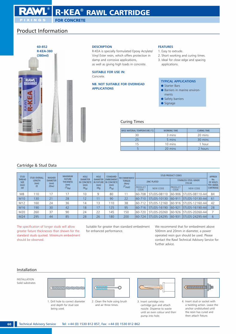
60 Technical Advisory Service Tel: +44 (0) 1530 812 857, Fax: +44 (0) 1530 812 862
R-KEA® RAWL CARTRIDGE
DESCRIPTIONR-KEA is specially formulated Epoxy Acrylate/Vinyl Ester resin, which offers protection in damp and corrosive applications, as well as giving high loads in concrete.
SUITABLE FOR USE IN:Concrete.
NB. NOT SUITABLE FOR OVERHEAD APPLICATIONS
FEATURES1. Easy to extrude.2. Short working and curing times.3. Ideal for close edge and spacing
applications.
Curing Times
BASE MATERIAL TEMPERATURE (°C) WORKING TIME CURING TIME
30 3 mins 20 mins25 5 mins 30 mins15 10 mins 1 hour
5 20 mins 2 hours
3. Insert cartridge into cartridge gun and attach nozzle. Dispense to waste until an even colour and then pump into hole.
4. Insert stud or socket with a twisting action. Leave the anchor undisturbed until the resin has cured and then attach fixture.
2. Clean the hole using brush and air three times.
Installation
1. Drill hole to correct diameter and depth for stud size being used.
INSTALLATIONSolid substrates
Cartridge & Stud Data
The specification of longer studs will allow greater fixture thicknesses than shown for the standard studs quoted. Minimum embedment should be observed.
Suitable for greater than standard embedment for enhanced performance.
We recommend that for embedment above 500mm and 20mm in diameter, a power operated resin gun should be used. Please contact the Rawl Technical Advisory Service for further advice.
STUD THREAD
SIZE (mm) (d)
STUD OVERALL LENGTH
(mm) (l)
WASHER DIAMETER
(mm)(Dw)
MAXIMUM FIXTURE
THICKNESS (mm) (T� x)
HOLE DIAMETER
IN CONCRETE (mm)(do)
HOLE DIAMETER IN FIXTURE
(mm) (df)
STANDARD EMBEDMENT IN CONCRETE
(mm)(ho)
RECOMMENDED TORQUE (Nm)
(Tinst)
STUD PRODUCT CODES APPROX No.
OF HOLES PER 380ML CARTRIDGE
ZINC PLATED STAINLESS STEEL GRADE 316 A4
PRODUCT CODE NEW CODE PRODUCT
CODE NEW CODE
M8 110 17 17 10 9 80 11 60-708 STUDS-08110 60-906 STUDS-08110-A4 84M10 130 21 28 12 11 90 22 60-710 STUDS-10130 60-911 STUDS-10130-A4 61M12 160 24 36 14 13 110 38 60-712 STUDS-12160 60-916 STUDS-12160-A4 42M16 190 30 42 18 17 125 95 60-716 STUDS-16190 60-921 STUDS-16190-A4 28M20 260 37 90 24 22 145 150 60-720 STUDS-20260 60-926 STUDS-20260-A4 7M24 295 44 85 28 26 180 200 60-724 STUDS-24295 60-931 STUDS-24295-A4 6
Product Information
60-852R-KEA-380(380ml)
FOR CONCRETE
TYPICAL APPLICATIONSe Starter Barse Barriers in marine environ-
mentse Safety barrierse Signage
RAWL_KATALOG_2007_2008.indb 60RAWL_KATALOG_2007_2008.indb 60 2007-10-15 14:36:382007-10-15 14:36:38

61Technical Advisory Service e-mail: [email protected] OR [email protected]
R-KEA® RAWL CARTRIDGE
Speci� cation Data
Reduction Factors – Edge and Spacing DistancesThe full characteristic edge and spacing distances shown in the table above are the minimum allowable for the quoted DESIGN RESISTANCE or RECOMMENDED LOAD, depending on your design method.Where these dimensions are not achievable, the appropriate reduction factor/s from the tables below must be applied to the DESIGN RESISTANCE or RECOMMENDED LOAD. Choose the required bolt diameter across the
top of the appropriate table and read down the left hand column until actual edge or spacing distance is found. Read off the reduction factor where the two lines intersect (interpolate as required). Multiply this factor by the DESIGN RESISTANCE or RECOMMENDED LOAD quoted in the table. On the occasion that multiple close edge and/or spacing distances occur, the appropriate reduction factors must be applied.
SIZE
CONCRETE, fck,cube = 30N/mm2 (C20/25)
CHARACTERISTIC RESISTANCE(kN) DESIGN RESISTANCE (Factored)(kN) RECOMMENDED LOAD (Unfactored)
(kN)CHARACTERISTIC EDGE DISTANCE
(mm)CHARACTERISTIC SPACING
(mm)
TENSION(NRk)
SHEAR(VRk)
TENSION(NRd)
SHEAR (VRd)
TENSION(Nrec)
SHEAR(VRec)
TENSION(Ccr,N)
SHEAR (Ccr,V)
TENSION & SHEAR(Scr,N) (Scr,V)
M8 14.3 9.9 6.3 7.9 4.5 5.7 80 100 100M10 22.4 15.7 9.6 12.6 6.9 9.0 90 130 130M12 30.6 22.9 12.4 18.3 8.9 13.1 110 150 150M16 48.7 42.5 19.4 34.0 13.9 24.3 130 170 170M20 67.1 66.8 25.2 53.4 18.0 38.2 150 190 210M24 81.7 95.7 28.2 76.6 20.1 54.7 190 240 240
Edge Distance (Concrete Only)
EDGE(mm)
TENSILE : EDGE REDUCTION FACTORS SHEAR : EDGE REDUCTION FACTORS
M8 M10 M12 M16 M20 M24 M8 M10 M12 M16 M20 M24
50 0.77 0.5060 0.85 0.80 0.60 0.5070 0.92 0.87 0.78 0.70 0.58 0.5080 1.00 0.93 0.84 0.80 0.66 0.5790 1.00 0.89 0.82 0.90 0.75 0.64 0.56
100 0.95 0.86 0.80 1.00 0.83 0.71 0.62 0.56110 1.00 0.91 0.84 0.77 0.92 0.78 0.69 0.61 0.50130 1.00 0.92 0.83 1.00 0.92 0.81 0.72 0.59150 1.00 0.90 1.00 0.94 0.83 0.68170 0.97 1.00 0.94 0.77190 1.00 1.00 0.86210 0.95240 1.00
Spacing (Concrete Only)
SPACING(mm)
TENSILE & SHEAR REDUCTION FACTORS
M8 M10 M12 M16 M20 M24
50 0.8060 0.84 0.8070 0.88 0.83 0.8080 0.92 0.87 0.8390 0.96 0.90 0.86 0.81
100 1.00 0.93 0.88 0.84 0.80110 0.97 0.91 0.86 0.82 0.79130 1.00 0.97 0.91 0.86 0.82150 1.00 0.95 0.90 0.85170 1.00 0.94 0.88190 0.98 0.92210 1.00 0.95240 1.00
REBAR DIA.(mm)
HOLE DIA.
DESIGN RESISTANCE (Fd)(kN)
EMBEDMENT DEPTH TO
FAIL REBAR(mm)
8 10 11.4 14.2 17.1 19.9 21.9 21.9 21.9 21.9 21.9 21.9 21.9 21.9 21.9 21.9 21.9 21.9 21.9 21.9 21.9 21.9 21.9 21.9 15410 12 15.9 19.1 22.3 25.4 28.6 31.8 34.2 34.2 34.2 34.2 34.2 34.2 34.2 34.2 34.2 34.2 34.2 34.2 34.2 34.2 34.2 21512 15 20.9 24.4 27.9 31.3 34.8 38.3 41.8 45.3 48.8 49.2 49.2 49.2 49.2 49.2 49.2 49.2 49.2 49.2 49.2 49.2 28314 18 MINIMUM
REBAR DEPTH26.3 30.1 33.9 37.6 41.4 45.1 48.9 52.7 56.4 60.2 63.9 66.9 66.9 66.9 66.9 66.9 66.9 66.9 66.9 356
16 20 32.2 36.2 40.2 44.2 48.3 52.3 56.3 60.3 64.3 68.4 72.4 76.4 80.4 84.4 87.4 87.4 87.4 87.4 435 DEPTH (mm) 80 100 120 140 160 180 200 220 240 260 280 300 320 340 360 380 400 420 440 460 480 500
20 25 45.0 50.6 56.2 61.8 67.4 78.7 89.9 101 112 124 135 137 137 137 137 137 137 137 137 137 137 137 60825 32 60.9 67.0 73.0 85.2 97.4 110 122 134 146 170 195 214 214 214 214 214 214 214 214 214 87732 40 MINIMUM
REBAR DEPTH80.0 93.3 107 120 133 147 160 187 213 240 267 293 320 347 350 350 350 350 1312
40 50 115 130 144 159 173 202 231 259 288 317 346 375 403 461 519 546 1897 DEPTH (mm) 200 225 250 275 300 350 400 450 500 550 600 700 800 900 1000 1100 1200 1300 1400 1600 1800 2000
REBAR DIA.(mm)
HOLE DIA.
RECOMMENDED LOAD (Frec)(kN)
EMBEDMENT DEPTH TO
FAIL REBAR(mm)
8 10 7.6 9.5 11.4 13.3 14.6 14.6 14.6 14.6 14.6 14.6 14.6 14.6 14.6 14.6 14.6 14.6 14.6 14.6 14.6 14.6 14.6 14.6 15410 12 10.6 12.7 14.9 16.9 19.1 21.2 22.8 22.8 22.8 22.8 22.8 22.8 22.8 22.8 22.8 22.8 22.8 22.8 22.8 22.8 22.8 21512 15 13.9 16.3 18.6 20.9 23.2 25.5 27.9 30.2 32.5 32.8 32.8 32.8 32.8 32.8 32.8 32.8 32.8 32.8 32.8 32.8 28314 18 MINIMUM
REBAR DEPTH17.5 20.1 22.6 25.1 27.6 30.1 32.6 35.1 37.6 40.1 42.6 4.6 44.6 44.6 44.6 44.6 44.6 44.6 44.6 356
16 20 21.5 24.1 26.8 29.5 32.2 34.9 37.5 40.2 42.9 45.6 48.3 50.9 53.6 56.3 58.3 58.3 58.3 58.3 435DEPTH (mm) 80 100 120 140 160 180 200 220 240 260 280 300 320 340 360 380 400 420 440 460 480 500
20 25 30.0 33.7 37.5 41.2 44.9 52.5 59.9 67.5 74.9 82.4 89.9 91.1 91.1 91.1 91.1 91.1 91.1 91.1 91.1 91.1 91.1 91.1 60825 32 40.6 44.7 48.7 56.8 64.9 73.1 81.1 89 97 114 130 142 142 142 142 142 142 142 142 142 87732 40 MINIMUM
REBAR DEPTH53.3 62.2 71.1 80.0 89 98 107 124 142 160 178 195 213 231 233 233 233 233 1312
40 50 76.8 86.4 96 106 115 134 154 173 192 211 230 250 269 307 346 364 1897DEPTH (mm) 200 225 250 275 300 350 400 450 500 550 600 700 800 900 1000 1100 1200 1300 1400 1600 1800 2000
Performance Data at Standard Embedment Depth
For further explanations on calculations please see pages 10 and 11
Concrete Strength Class:C20/25 (25N/mm2 150mm Cylinder; 30N/mm2 150mm Cube).
Reinforcement Bar: Minimum Yield Strength fyk 460N/mm2.
Note: Performance based on clean holes; blown and then brushed with a stiff nylon brush.
Performance Data for Reinforcement Bars
If you are bonding rebar into reinforced concrete, where the size, position etc. of the reinforcing is known, then designprinciples containedwithin Eurocode 2 can be adopted instead of the design recommendationscontained within this manual.
FOR CONCRETE
RAWL_KATALOG_2007_2008.indb 61RAWL_KATALOG_2007_2008.indb 61 2007-10-15 14:36:432007-10-15 14:36:43

62 Technical Advisory Service Tel: +44 (0) 1530 812 857, Fax: +44 (0) 1530 812 862
The specification of longer studs will allow greater fixture thicknesses than shown for the standard studs quoted. Minimum embedment should be observed.
Note: For perforated brickwork and hollow block work a mesh sleeve must be inserted into the hole prior to the resin being pumped.
We recommend that for embedment above 500mm and 20mm in diameter a power operated resin gun should be used. Please contact the Rawl Technical Advisory Service for further advice.
DESCRIPTIONR-KEM+ is a high performance, styrene free system that is suitable for use in concrete, and other solid or hollow masonry structures. This makes it ideal for applications where conventional expansion anchors present problems.
SUITABLE FOR USE IN:ConcreteBrickworkBlockworkStone
FEATURES1. Suitable for solid and hollow substrates.2. Suitable for overhead applications (with care).3. R-KEM+ fits a standard mastic gun.4. Styrene free.5. Suitable for use in confined spaces
Installation
INSTALLATIONSolid substrates
INSTALLATIONHollow substrates & substrates with voids
1. Drill hole to correct diameter and depth for stud size being used.
2. Clean the hole using brush and air three times.
3. Insert cartridge into cartridge gun and attach nozzle. Dispense to waste until an even colour and then pump into hole.
4. Insert stud or socket with a twisting action. Leave the anchor undisturbed until the resin has cured and then attach fixture.
1. Drill hole to correct diameter and depth for mesh sleeve size being used.
2. Insert sleeve into hole. 4. Insert stud or socket with a twisting action. Leave the anchor undisturbed until the resin has set and then attach fixture.
3. Insert cartridge into cartridge gun and attach nozzle. Dispense to waste until even colour. Then insert nozzle and pump to fill sleeve.
60-270R-KEM-300(300ml)
Cartridge & Stud Data
Curing Times
BASE MATERIAL TEMPERATURE (°C) WORKING TIME CURING TIME
30 3 mins 25 mins20 7 mins 50 mins10 22 mins 1 hour 30 mins5 30 mins 3 hours 20 mins
Product Information
STUD THREAD SIZE (mm) (d)
STUD OVERALL LENGTH
(mm) (l)
WASHER DIAMETER
(mm)(Dw)
MAXIMUM FIXTURE
THICKNESS (mm) (T� x)
HOLE DIAMETER
IN CONCRETE
(mm)(do)
HOLE DIAMETER
IN FIXTURE
(mm) (df)
STANDARD EMBEDMENT
IN CONCRETE
(mm)(ho)
RECOMMENDED TORQUE (Nm)
(Tinst)
STUD PRODUCT CODESAPPROX No. OF HOLES
PER 300ML CARTRIDGE
ZINC PLATED
STAINLESS STEEL GRADE 316 A4
CONCRETE BRICKWORK PRODUCT CODE NEW CODE PRODUCT
CODE NEW CODE
M8 110 17 17 10 9 80 11 2 60-708 STUDS-08110 60-906 STUDS-08110-A4 66M10 130 21 28 12 11 90 22 6 60-710 STUDS-10130 60-911 STUDS-10130-A4 48M12 160 24 36 14 13 110 38 11 60-712 STUDS-12160 60-916 STUDS-12160-A4 33M16 190 30 42 18 17 125 95 24 60-716 STUDS-16190 60-921 STUDS-16190-A4 22M20 260 37 90 24 22 145 150 - 60-720 STUDS-20260 60-926 STUDS-20260-A4 6
M20 DEEP 260 37 55 24 22 180 150 - 60-720 STUDS-20260 60-926 STUDS-20260-A4 5M24 295 44 85 28 26 180 200 - 60-724 STUDS-24295 60-931 STUDS-24295-A4 5
M24 DEEP 295 44 55 28 26 210 200 - 60-724 STUDS-24295 60-931 STUDS-24295-A4 4
R-KEM+® RAWL CARTRIDGE
FOR CONCRETE, BRICK, BLOCK AND STONE
TYPICAL APPLICATIONSe Curtain wallinge Balustradinge Handrailse Canopiese Rebar
RAWL_KATALOG_2007_2008.indb 62RAWL_KATALOG_2007_2008.indb 62 2007-10-15 14:36:442007-10-15 14:36:44

63Technical Advisory Service e-mail: [email protected] OR [email protected]
R-KEM+® RAWL CARTRIDGE
FOR CONCRETE, BRICK, BLOCK AND STONE
Reduction Factors – Edge and Spacing DistancesThe full characteristic edge and spacing distances shown in the table above are the minimum allowable for the quoted DESIGN RESISTANCE or RECOMMENDED LOAD, depending on your design method. Where these dimensions are not achievable, the appropriate reduction factor/s from the tables below must be applied to the DESIGN RESISTANCE or RECOMMENDED LOAD. Choose the required bolt diameter across the
top of the appropriate table and read down the left hand column until actual edge or spacing distance is found. Read off the reduction factor where the two lines intersect (interpolate as required). Multiply this factor by the DESIGN RESISTANCE or RECOMMENDED LOAD quoted in the table. On the occasion that multiple close edge and/or spacing distances occur, the appropriate reduction factors must be applied.
Performance Data for Reinforcement Bars
REBAR DIA.(mm)
HOLE DIA. DESIGN RESISTANCE (Fd)(kN)
EMBEDMENT DEPTH TO
FAIL REBAR(mm)
8 10 10.7 13.3 16.0 18.7 21.3 21.9 21.9 21.9 21.9 21.9 21.9 21.9 21.9 21.9 21.9 21.9 21.9 21.9 21.9 21.9 21.9 21.9 16410 12 14.9 17.9 20.9 23.8 26.8 29.8 32.8 34.2 34.2 34.2 34.2 34.2 34.2 34.2 34.2 34.2 34.2 34.2 34.2 34.2 34.2 23012 15 19.6 22.9 26.1 29.4 32.6 35.9 39.2 42.4 45.7 49.0 49.2 49.2 49.2 49.2 49.2 49.2 49.2 49.2 49.2 49.2 30114 18 MINIMUM
REBAR DEPTH24.7 28.2 31.7 35.3 38.8 42.3 45.8 49.4 52.9 56.4 59.9 63.5 66.9 66.9 66.9 66.9 66.9 66.9 66.9 379
16 20 30.2 33.9 37.7 41.5 45.2 49.0 52.8 56.5 60.3 64.1 67.9 71.6 75.4 79.2 82.9 86.7 87.4 87.4 464 DEPTH (mm) 80 100 120 140 160 180 200 220 240 260 280 300 320 340 360 380 400 420 440 460 480 500
20 25 42.1 47.4 52.7 61.8 67.4 78.7 84.3 94.8 105 116 126 137 137 137 137 137 137 137 137 137 137 137 64825 32 56.9 62.6 68.3 79.7 91.1 103 114 125 137 159 182 205 214 214 214 214 214 214 214 214 93732 40 MINIMUM
REBAR DEPTH74.6 87.1 99.5 112 124 137 149 174 199 224 249 274 299 323 350 350 350 350 1406
40 50 107 121 134 148 161 188 215 241 268 295 322 349 402 456 510 546 2037 DEPTH (mm) 200 225 250 275 300 350 400 450 500 550 600 700 800 900 1000 1100 1200 1300 1500 1700 1900 2100
Performance Data at Standard Embedment Depth
REBAR DIA.(mm)
HOLE DIA. RECOMMENDED LOAD (Frec)(kN)
EMBEDMENT DEPTH TO
FAIL REBAR(mm)
8 10 7.1 8.9 10.7 12.5 14.2 14.6 14.6 14.6 14.6 14.6 14.6 14.6 14.6 14.6 14.6 14.6 14.6 14.6 14.6 14.6 14.6 14.6 16410 12 9.9 11.9 13.9 15.9 17.9 19.9 21.9 22.8 22.8 22.8 22.8 22.8 22.8 22.8 22.8 22.8 22.8 22.8 22.8 22.8 22.8 23012 15 13.1 15.3 17.4 19.6 21.7 23.9 26.1 28.3 30.5 32.7 32.8 32.8 32.8 32.8 32.8 32.8 32.8 32.8 32.8 32.8 30114 18 MINIMUM
REBAR DEPTH16.5 18.8 21.1 23.5 25.9 28.2 30.5 32.9 35.3 37.6 39.9 42.3 44.6 44.6 44.6 44.6 44.6 44.6 44.6 379
16 20 20.1 22.6 25.1 27.7 30.1 32.7 35.2 37.7 40.2 42.7 45.3 47.7 50.3 52.8 55.3 57.8 58.3 58.3 464 DEPTH (mm) 80 100 120 140 160 180 200 220 240 260 280 300 320 340 360 380 400 420 440 460 480 500
20 25 28.1 31.6 35.1 41.2 44.9 52.5 56.2 63.2 70.3 77.3 84.3 91.1 91.1 91.1 91.1 91.1 91.1 91.1 91.1 91.1 91.1 91.1 64825 32 37.9 41.7 45.5 53.1 60.7 68.3 75.9 84 91 106 121 137 142 142 142 142 142 142 142 142 93732 40 MINIMUM
REBAR DEPTH49.7 58.1 66.3 74.7 83 91 100 116 133 149 166 182 199 216 233 233 233 233 1406
40 50 71.5 80.5 89 98 107 125 143 161 179 197 215 232 268 304 340 364 2037 DEPTH (mm) 200 225 250 275 300 350 400 450 500 550 600 700 800 900 1000 1100 1200 1300 1500 1700 1900 2100
Speci� cation Data
SIZE
RECOMMENDED LOAD (kN) (Unfactored)TENSION OR SHEAR (Frec)
BRICKWORK 20.5N/mm2
BLOCKWORK 7N/mm2
BLOCKWORK 3.5N/mm2
BLOCKWORK 2.8N/mm2
M8 1.4 0.6 0.5 0.4M10 2.9 1.3 0.9 0.7M12 4.0 2.0 1.1 0.9M16 5.0 3.0
SIZES ABOVE M12 ARE NOT RECOMMENDEDM20 SIZES ABOVE M16
ARE NOT RECOMMENDEDM24
SIZE
CONCRETE, fck,cube = 30N/mm2 (C20/25)CHARACTERISTIC
RESISTANCE(kN)
DESIGN RESISTANCE (Factored) (kN)
RECOMMENDED LOAD (Unfactored) (kN)
CHARACTERISTIC EDGE DISTANCE
(mm)
CHARACTERISTIC SPACING
(mm)
TENSION(NRk)
SHEAR(VRk)
TENSION(NRd)
SHEAR(VRd)
TENSION(Nrec)
SHEAR(Vrec)
TENSION(Ccr,N)
SHEAR(Ccr,V)
TENSION & SHEAR(Scr,N) (Scr,V)
M8 11.5 9.9 5.1 7.9 3.6 5.7 80 100 100M10 20.0 15.7 8.3 12.6 5.9 9.0 90 130 130M12 28.7 22.9 11.5 18.3 8.2 13.1 110 150 150M16 45.7 42.5 16.6 34.0 11.9 24.3 130 170 170M20 62.0 66.8 20.9 53.4 15.0 38.2 150 190 210
M20 DEEP 69.7 66.8 23.2 53.4 16.6 38.2 180 190 230M24 79.3 95.7 26.4 76.6 18.9 54.7 190 240 240
M24 DEEP 87.9 95.7 29.3 76.6 20.9 54.7 220 240 270
For further explanations on calculations please see pages 10 and 11.
EDGE(mm)
TENSILE : EDGE REDUCTION FACTORS SHEAR : EDGE REDUCTION FACTORS
M8 M10 M12 M16 M20 M20 DEEP M24 M24
DEEP M8 M10 M12 M16 M20 M24
50 0.77 0.5060 0.85 0.80 0.60 0.5070 0.92 0.87 0.78 0.70 0.58 0.5080 1.00 0.93 0.84 0.80 0.66 0.5790 1.00 0.89 0.82 0.90 0.75 0.64 0.56100 0.95 0.86 0.80 1.00 0.83 0.71 0.62 0.56110 1.00 0.91 0.84 0.77 0.77 0.92 0.78 0.69 0.61 0.50130 1.00 0.92 0.83 0.83 0.76 1.00 0.92 0.81 0.72 0.59150 1.00 0.90 0.90 0.81 1.00 0.94 0.83 0.68170 0.97 0.96 0.86 1.00 0.94 0.77180 1.00 0.98 0.89 0.98 0.81190 1.00 0.92 1.00 0.86220 1.00 0.97240 1.00
SPACING(mm)
TENSILE & SHEAR REDUCTION FACTORS
M8 M10 M12 M16 M20 M20 DEEP M24 M24
DEEP50 0.8060 0.84 0.8070 0.88 0.83 0.8080 0.92 0.87 0.8390 0.96 0.90 0.86 0.81100 1.00 0.93 0.88 0.84 0.80110 0.97 0.91 0.86 0.82 0.80 0.79130 1.00 0.97 0.91 0.86 0.84 0.83 0.80150 1.00 0.95 0.90 0.87 0.86 0.83170 1.00 0.94 0.90 0.89 0.86210 1.00 0.97 0.95 0.92230 1.00 0.98 0.95240 1.00 0.97270 1.00
Edge Distance (Concrete Only) Spacing (Concrete Only)
Concrete Strength Class:C20/25 (25N/mm2 150mm Cylinder; 30N/mm2 150mm Cube).
Reinforcement Bar: Minimum Yield Strength fyk 460N/mm2.
Note: Performance based on clean holes; blown and then brushed with a stiff nylon brush.
If you are bonding rebar into reinforced concrete, where the size, position etc. of the reinforcing is known, then designprinciples containedwithin Eurocode 2 can be adopted instead of the design recommendationscontained within this manual.
When calculating loads in brickwork, apply the published edge distance and spacing for concrete and assume these � gures to be the absolute minimums. Concrete reduction factors must NOT be applied.
RAWL_KATALOG_2007_2008.indb 63RAWL_KATALOG_2007_2008.indb 63 2007-10-15 14:36:502007-10-15 14:36:50

64 Technical Advisory Service Tel: +44 (0) 1530 812 857, Fax: +44 (0) 1530 812 862
R-KF2/KSF® RAWL CARTRIDGE
FOR CONCRETE, BRICK, BLOCK AND STONE
The specification of longer studs will allow greater fixture thicknesses than shown for the standard studs quoted. Minimum embedment should be observed.
We recommend that embedment above 500mm and 20mm in diameter a power operated resin gun should be used.
Please contact the Rawl Technical Advisory Service for further advice.
DESCRIPTIONR-KF2 and R-KSF are general purpose resins, for solid and hollow structures with both products having a relatively short cure time.
SUITABLE FOR USE IN:ConcreteBrickworkBlockworkStoneOverhead Applications
FEATURES1. Suitable for Solid and Hollow
substrates.2. 150ml R-KSF is ideal for small
applications.3. R-KSF fits a standard
mastic gun.4. R-KSF Odourless and
Styrene free.
Installation
INSTALLATIONSolid substrates
1. Drill hole to correct diameter and depth for stud size being used.
2. Clean the hole using brush and air three times.
3. Insert cartridge into cartridge gun and attach nozzle. Dispense to waste until an even colour and then pump into hole.
4. Insert stud or socket with a twisting action. Leave the anchor undisturbed until the resin has cured and then attach fixture.
INSTALLATIONHollow substrates & substrates with voids
1. Drill hole to correct diameter and depth for mesh sleeve size being used.
2. Insert sleeve into hole. 3. Insert cartridge into cartridge gun and attach nozzle. Dispense to waste until even colour. Then insert nozzle and pump to fill sleeve.
4. Insert stud or socket with a twisting action. Leave the anchor undisturbed until the resin has set and then attach fixture.
60-200R-KF2-380(380ml)
60-150R-KSF-150(150ml)
Cartridge & Stud Data
STUD THREAD
SIZE (mm) (d)
STUD OVERALL LENGTH
(mm) (l)
WASHER DIAMETER
(mm)(Dw)
MAXIMUM FIXTURE
THICKNESS (mm) (T� x)
HOLE DIAMETER
IN CONCRETE
(mm)(do)
HOLE DIAMETER IN FIXTURE
(mm) (df)
STANDARD EMBEDMENT
IN CONCRETE
(mm)(ho)
RECOMMENDED TORQUE (Nm)
(Tinst)
STUD PRODUCT CODES APPROX No OF HOLES
PER 380ML CARTRIDGE
ZINC PLATED STAINLESS STEEL GRADE 316 A4
CONCRETE BRICKWORK PRODUCT CODE NEW CODE PRODUCT
CODE NEW CODE 380ml 150ml
M8 110 17 17 10 9 80 3 2 60-708 STUDS-08110 60-906 STUDS-08110-A4 84 33M10 130 21 28 12 11 90 9 6 60-710 STUDS-10130 60-911 STUDS-10130-A4 61 24M12 160 24 36 14 13 110 17 11 60-712 STUDS-12160 60-916 STUDS-12160-A4 42 16M16 190 30 42 18 17 125 36 24 60-716 STUDS-16190 60-921 STUDS-16190-A4 28 11M20 260 37 90 24 22 145 53 - 60-720 STUDS-20260 60-926 STUDS-20260-A4 7 3M24 295 44 85 28 26 180 60 - 60-724 STUDS-24295 60-931 STUDS-24295-A4 6 2
R-KF2
BASE MATERIAL TEMPERATURE
(°C)
WORKING TIME
CURING TIME
30 4 mins 30 mins25 7 mins 1 hour15 15 mins 2 hours
5 30 mins 3 hours
R-KSF
BASE MATERIAL TEMPERATURE
(°C)
WORKING TIME CURING TIME
30 4 mins 30 mins20 8 mins 50 mins15 14 mins 2 hours
5 30 mins 4 hours
Note: For perforated brickwork and hollow block work a mesh sleeve must be inserted into the hole prior to the resin being pumped.Studs over 16mm diameter are not recommended in brickwork.
Product Information
TYPICAL APPLICATIONSe Masonry supporte Fixing into tarmac
RAWL_KATALOG_2007_2008.indb 64RAWL_KATALOG_2007_2008.indb 64 2007-10-15 14:36:522007-10-15 14:36:52

65Technical Advisory Service e-mail: [email protected] OR [email protected]
R-KF2/KSF® RAWL CARTRIDGE
FOR CONCRETE, BRICK, BLOCK AND STONE
If you are bonding rebar into
reinforced concrete, where
the size, position etc. of the
reinforcing is known, then
design principles contained
within Eurocode 2 can be
adopted instead of the design
recommendations contained
within this manual.
Reduction Factors – Edge and Spacing DistancesThe full characteristic edge and spacing distances shown in the table above are the minimum allowable for the quoted DESIGN RESISTANCE or RECOMMENDED LOAD, depending on your design method. Where these dimensions are not achievable, the appropriate reduction factor/s from the tables below must be applied to the DESIGN RESISTANCE or RECOMMENDED LOAD. Choose the required bolt diameter across the
top of the appropriate table and read down the left hand column until actual edge or spacing distance is found. Read off the reduction factor where the two lines intersect (interpolate as required). Multiply this factor by the DESIGN RESISTANCE or RECOMMENDED LOAD quoted in the table. On the occasion that multiple close edge and/or spacing distances occur, the appropriate reduction factors must be applied.
Performance Data for Reinforcement Bars
Speci� cation Data
Performance Data at Standard Embedment Depth
SIZE
CONCRETE, fck,cube = 30N/mm2 (C20/25)
CHARACTERISTIC RESISTANCE (kN)
DESIGN RESISTANCE(Factored) (kN)
RECOMMENDED LOAD (Unfactored)
(kN)
CHARACTERISTIC EDGE DISTANCE
(mm)
CHARACTERISTIC SPACING
(mm)TENSION(NRk)
SHEAR(VRk)
TENSION (NRd)
SHEAR(VRd)
TENSION(Nrec)
SHEAR(Vrec)
TENSION (Ccr,N)
SHEAR(Ccr,V)
TENSION & SHEAR(Scr,N) (Scr,V)
M8 9.5 9.9 4.1 7.9 2.9 5.7 60 80 80M10 16.4 15.7 6.5 12.6 4.7 9.0 70 90 90M12 25.7 22.9 9.7 18.3 6.9 13.1 80 110 110M16 42.5 42.5 14.7 34.0 10.5 24.3 90 130 130M20 52.0 66.8 17.6 53.4 12.6 38.2 110 150 150M24 61.9 95.7 20.0 76.6 14.3 54.7 130 170 170
SIZE
RECOMMENDED LOAD (kN) (Unfactored)TENSION OR SHEAR (Frec)
BRICKWORK 20.5N/mm2
BLOCKWORK 7N/mm2
BLOCKWORK 3.5N/mm2
BLOCKWORK 2.8N/mm2
M8 1.4 0.6 0.5 0.4M10 2.9 1.3 0.9 0.7M12 4.0 2.0 1.1 0.9M16 5.0 3.0
SIZES ABOVE M12 ARE NOT RECOMMENDEDM20 SIZES ABOVE M16
ARE NOT RECOMMENDEDM24
Edge Distance (Concrete Only)
EDGE(mm)
TENSILE : EDGE REDUCTION FACTORS SHEAR : EDGE REDUCTION FACTORSM8 M10 M12 M16 M20 M24 M8 M10 M12 M16 M20 M24
40 0.80 0.5050 0.90 0.83 0.62 0.5660 1.0 0.91 0.85 0.75 0.66 0.5470 1.0 0.92 0.87 0.78 0.6480 1.0 0.93 1.0 0.89 0.72 0.6290 1.0 0.89 0.85 1.0 0.82 0.69 0.60100 0.95 0.89 0.91 0.77 0.66 0.60110 1.0 0.95 1.0 0.84 0.73 0.66130 1.0 1.0 0.86 0.73150 1.0 0.86170 1.0
Spacing (Concrete Only)
SPACING(mm)
TENSILE & SHEAR REDUCTION FACTORSM8 M10 M12 M16 M20 M24
40 0.8050 0.85 0.8260 0.90 0.87 0.8270 0.95 0.91 0.8580 1.0 0.95 0.89 0.8590 1.0 0.93 0.88 0.84100 0.96 0.91 0.87 0.84110 1.0 0.94 0.89 0.87130 1.0 0.95 0.89150 1.0 0.95170 1.0
REBAR DIA.(mm)
HOLE DIA.
DESIGN RESISTANCE (Fd)(kN)
EMBEDMENT DEPTH TO
FAIL REBAR(mm)
8 10 10.0 12.4 14.9 17.4 19.9 21.9 21.9 21.9 21.9 21.9 21.9 21.9 21.9 21.9 21.9 21.9 21.9 21.9 21.9 21.9 21.9 21.9 17610 12 13.9 16.7 19.5 22.3 25.0 27.8 30.6 33.4 34.2 34.2 34.2 34.2 34.2 34.2 34.2 34.2 34.2 34.2 34.2 34.2 34.2 24612 15 18.3 21.3 24.4 27.4 30.5 33.5 36.6 39.6 42.7 45.7 48.8 49.2 49.2 49.2 49.2 49.2 49.2 49.2 49.2 49.2 32314 18 MINIMUM
REBAR DEPTH23.0 26.3 29.6 32.9 36.2 39.5 42.8 46.1 49.4 52.7 56.0 59.2 62.5 65.8 66.9 66.9 66.9 66.9 66.9 407
16 20 28.1 31.7 35.2 38.7 42.2 45.7 49.3 52.8 56.3 59.8 63.3 66.9 70.4 73.9 77.4 80.9 84.4 87.4 497 DEPTH (mm) 80 100 120 140 160 180 200 220 240 260 280 300 320 340 360 380 400 420 440 460 480 500
20 25 39.3 44.3 49.2 54.1 59.0 68.8 78.7 88.5 98.3 108 118 128 137 137 137 137 137 137 137 137 137 137 69425 32 53.0 58.3 63.6 74.2 84.8 95.4 106 117 127 138 148 170 191 212 214 214 214 214 214 214 100732 40 MINIMUM
REBAR DEPTH69.3 80.9 92.4 104 116 127 139 150 162 185 208 321 277 323 350 350 350 350 1514
40 50 99.3 112 124 137 149 161 174 199 224 248 298 348 397 447 497 546 2200 DEPTH (mm) 200 225 250 275 300 350 400 450 500 550 600 650 700 800 900 1000 1200 1400 1600 1800 2000 2200
REBAR DIA.(mm)
HOLE DIA.
RECOMMENDED LOAD (Frec)(kN)
EMBEDMENT DEPTH TO
FAIL REBAR(mm)
8 10 6.7 8.3 9.9 11.6 13.3 14.6 14.6 14.6 14.6 14.6 14.6 14.6 14.6 14.6 14.6 14.6 14.6 14.6 14.6 14.6 14.6 14.6 17610 12 9.3 11.1 13.0 14.9 16.7 18.5 20.4 22.3 22.8 22.8 22.8 22.8 22.8 22.8 22.8 22.8 22.8 22.8 22.8 22.8 22.8 24612 15 12.2 14.2 16.3 18.3 20.3 22.3 24.4 26.4 28.5 30.5 32.5 32.8 32.8 32.8 32.8 32.8 32.8 32.8 32.8 32.8 32314 18 MINIMUM
REBAR DEPTH15.3 17.5 19.7 21.9 24.1 26.3 28.5 30.7 32.9 35.1 37.3 39.5 41.7 43.9 44.6 44.6 44.6 44.6 44.6 407
16 20 18.7 21.1 23.5 25.8 28.1 30.5 32.9 35.2 37.5 39.9 42.2 44.6 46.9 49.3 51.6 53.9 56.3 58.3 497DEPTH (mm) 80 100 120 140 160 180 200 220 240 260 280 300 320 340 360 380 400 420 440 460 480 500
20 25 26.2 29.5 32.8 36.1 39.3 45.9 52.5 59.0 65.5 72.1 78.7 85.3 91.1 91.1 91.1 91.1 91.1 91.1 91.1 91.1 91.1 91.1 69425 32 35.3 38.9 42.4 49.5 56.5 63.6 70.7 78 85 92 99 113 127 141 142 142 142 142 142 142 100732 40 MINIMUM
REBAR DEPTH 46.2 53.9 61.6 69.3 77 85 92 100 108 123 139 154 185 216 233 233 233 233 1514
40 50 66.2 74.5 83 91 99 108 116 132 149 166 199 232 265 298 331 364 2200DEPTH (mm) 200 225 250 275 300 350 400 450 500 550 600 650 700 800 900 1000 1200 1400 1600 1800 2000 2200
For further explanations on calculations please see pages 10 and 11.
Concrete Strength Class:C20/25 (25N/mm2 150mm Cylinder; 30N/mm2 150mm Cube).
Reinforcement Bar: Minimum Yield Strength fyk 460N/mm2.
Note: Performance based on clean holes; blown and then brushed with a stiff nylon brush.
When calculating loads in brickwork, apply the published edge distance and spacing for concrete and assume these � gures to be the absolute minimums. Concrete reduction factors must NOT be applied.
RAWL_KATALOG_2007_2008.indb 65RAWL_KATALOG_2007_2008.indb 65 2007-10-15 14:37:012007-10-15 14:37:01
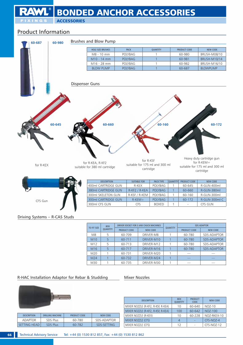
66 Technical Advisory Service Tel: +44 (0) 1530 812 857, Fax: +44 (0) 1530 812 862
ACCESSORIES
BONDED ANCHOR ACCESSORIES
60-687 60-980
R-HAC Installation Adaptor for Rebar & Studding
Brushes and Blow Pump
HOLE SIZE BRUSHES PACK QUANTITY PRODUCT CODE NEW CODE
M8 - 10 mm POLYBAG 1 60-980 BRUSH-M08/10M10 - 14 mm POLYBAG 1 60-981 BRUSH-M10/14M16 - 28 mm POLYBAG 1 60-982 BRUSH-M16/10BLOW PUMP POLYBAG 1 60-687 BLOWPUMP
DESCRIPTION BOX QUANTITY
PRODUCT CODE NEW CODE
MIXER NOZZLE (R-KF2, R-KSF, R-KEA) 10 60-640 NOZ-10MIXER NOZZLE (R-KF2, R-KSF, R-KEA) 100 60-642 NOZ-100MIXER NOZZLE (R-KEX) 10 60-228 NOZ-RKEX-10MIXER NOZZLE (CFS) 4 - CFS-NOZ-4MIXER NOZZLE (CFS) 12 - CFS-NOZ-12
DESCRIPTION DRILLING MACHINE PRODUCT CODE NEW CODE
ADAPTOR SDS Plus 60-780 SDS-ADAPTORSETTING HEAD SDS Plus 60-782 SDS-SETTING
Driving Systems – R-CAS Studs
TO FIT SIZE BOX QUANTITY
DRIVER SOCKET FOR 3 JAW CHUCK MACHINESQUANTITY
SDS ADAPTOR
PRODUCT CODE NEW CODE PRODUCT CODE NEW CODE
M8 5 60-709 DRIVER-M8 1 60-780 SDS-ADAPTORM10 5 60-711 DRIVER-M10 1 60-780 SDS-ADAPTORM12 5 60-713 DRIVER-M12 1 60-780 SDS-ADAPTORM16 5 60-717 DRIVER-M16 1 60-780 SDS-ADAPTORM20 1 60-731 DRIVER-M20 1 — —M24 1 60-732 DRIVER-M24 1 — —M30 1 60-735 DRIVER-M30 1 — —
DESCRIPTION SUITABLE FOR PACK TYPE QUANTITY PRODUCT CODE NEW CODE
400ml CARTRIDGE GUN R-KEX POLYBAG 1 60-645 R-GUN-400ml380ml CARTRIDGE GUN R-KF2 / R-KEA POLYBAG 1 60-660 R-GUN-380ml300ml SKELETON GUN R-KSF / R-KEM POLYBAG 1 60-160 R-GUN-300ml300ml CARTRIDGE GUN R-KEM+ POLYBAG 1 60-172 R-GUN-300ml-C300ml CFS GUN CFS BOXED 1 - CFS GUN
Product Information
60-645 60-660 60-17260-160
for R-KEXfor R-KEA, R-KF2
suitable for 380 ml cartridge
for R-KSFsuitable for 175 ml and 300 ml
cartridge
Heavy duty cartridge gun for R-KEM+
suitable for 175 ml and 300 ml cartridge
Dispenser Guns
Mixer Nozzles
CFS Gun
RAWL_KATALOG_2007_2008.indb 66RAWL_KATALOG_2007_2008.indb 66 2007-10-15 14:37:032007-10-15 14:37:03
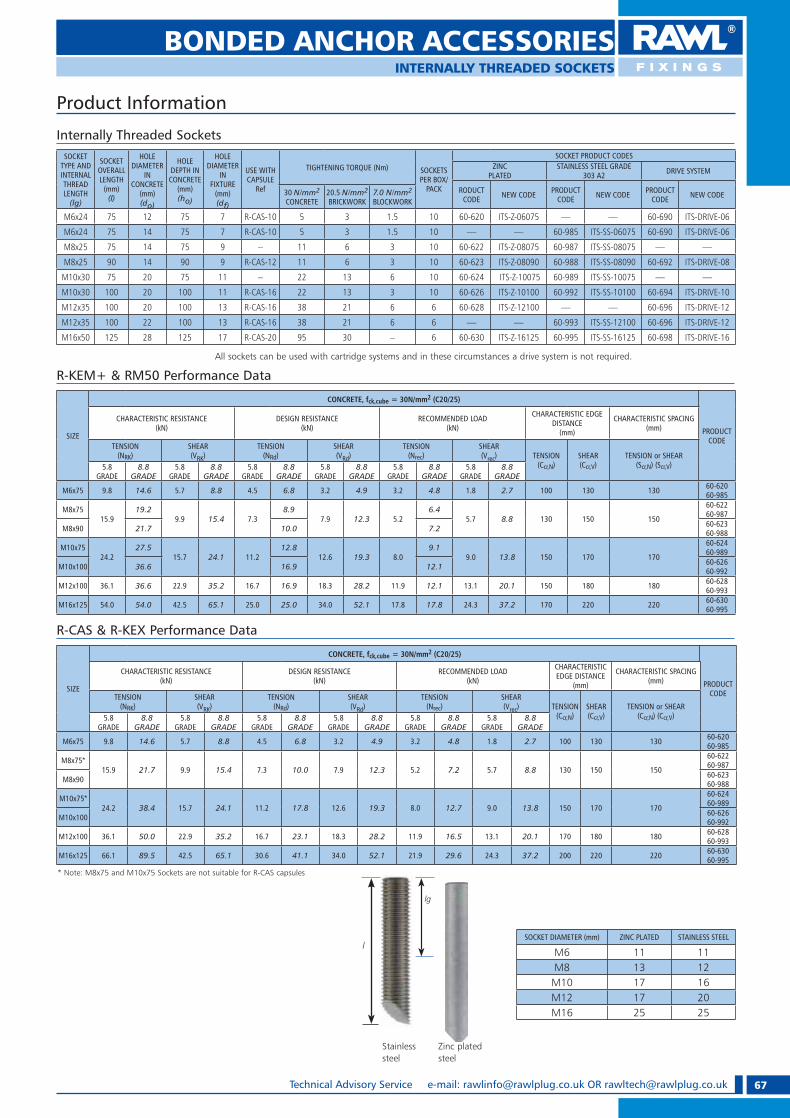
67Technical Advisory Service e-mail: [email protected] OR [email protected]
Internally Threaded Sockets
BONDED ANCHOR ACCESSORIESINTERNALLY THREADED SOCKETS
SOCKET DIAMETER (mm) ZINC PLATED STAINLESS STEEL
M6 11 11M8 13 12M10 17 16M12 17 20M16 25 25
All sockets can be used with cartridge systems and in these circumstances a drive system is not required.
SOCKET TYPE AND INTERNAL THREAD LENGTH
(lg)
SOCKET OVERALL LENGTH
(mm)(l)
HOLE DIAMETER
IN CONCRETE
(mm)(do)
HOLE DEPTH IN CONCRETE
(mm)(ho)
HOLE DIAMETER
INFIXTURE
(mm)(df)
USE WITH CAPSULE
Ref
TIGHTENING TORQUE (Nm) SOCKETS PER BOX/
PACK
SOCKET PRODUCT CODESZINC
PLATEDSTAINLESS STEEL GRADE
303 A2 DRIVE SYSTEM
RODUCT CODE NEW CODE PRODUCT
CODE NEW CODE PRODUCT CODE NEW CODE30 N/mm2
CONCRETE20.5 N/mm2 BRICKWORK
7.0 N/mm2 BLOCKWORK
M6x24 75 12 75 7 R-CAS-10 5 3 1.5 10 60-620 ITS-Z-06075 — — 60-690 ITS-DRIVE-06
M6x24 75 14 75 7 R-CAS-10 5 3 1.5 10 — — 60-985 ITS-SS-06075 60-690 ITS-DRIVE-06
M8x25 75 14 75 9 – 11 6 3 10 60-622 ITS-Z-08075 60-987 ITS-SS-08075 — —
M8x25 90 14 90 9 R-CAS-12 11 6 3 10 60-623 ITS-Z-08090 60-988 ITS-SS-08090 60-692 ITS-DRIVE-08
M10x30 75 20 75 11 – 22 13 6 10 60-624 ITS-Z-10075 60-989 ITS-SS-10075 — —
M10x30 100 20 100 11 R-CAS-16 22 13 3 10 60-626 ITS-Z-10100 60-992 ITS-SS-10100 60-694 ITS-DRIVE-10
M12x35 100 20 100 13 R-CAS-16 38 21 6 6 60-628 ITS-Z-12100 — — 60-696 ITS-DRIVE-12
M12x35 100 22 100 13 R-CAS-16 38 21 6 6 — — 60-993 ITS-SS-12100 60-696 ITS-DRIVE-12
M16x50 125 28 125 17 R-CAS-20 95 30 – 6 60-630 ITS-Z-16125 60-995 ITS-SS-16125 60-698 ITS-DRIVE-16
Product Information
SIZE
CONCRETE, fck,cube = 30N/mm2 (C20/25)
PRODUCT CODE
CHARACTERISTIC RESISTANCE (kN)
DESIGN RESISTANCE (kN)
RECOMMENDED LOAD (kN)
CHARACTERISTIC EDGE DISTANCE
(mm)
CHARACTERISTIC SPACING(mm)
TENSION(NRK)
SHEAR(VRK)
TENSION(NRd)
SHEAR(VRd)
TENSION(Nrec)
SHEAR(Vrec) TENSION
(Ccr,N)SHEAR(Ccr,V)
TENSION or SHEAR(Scr,N) (Scr,V)5.8
GRADE8.8
GRADE5.8
GRADE8.8
GRADE5.8
GRADE8.8
GRADE5.8
GRADE8.8
GRADE5.8
GRADE8.8
GRADE5.8
GRADE8.8
GRADE
M6x75 9.8 14.6 5.7 8.8 4.5 6.8 3.2 4.9 3.2 4.8 1.8 2.7 100 130 130 60-62060-985
M8x7515.9
19.29.9 15.4 7.3
8.97.9 12.3 5.2
6.45.7 8.8 130 150 150
60-62260-987
M8x90 21.7 10.0 7.2 60-62360-988
M10x7524.2
27.515.7 24.1 11.2
12.812.6 19.3 8.0
9.19.0 13.8 150 170 170
60-62460-989
M10x100 36.6 16.9 12.1 60-62660-992
M12x100 36.1 36.6 22.9 35.2 16.7 16.9 18.3 28.2 11.9 12.1 13.1 20.1 150 180 180 60-62860-993
M16x125 54.0 54.0 42.5 65.1 25.0 25.0 34.0 52.1 17.8 17.8 24.3 37.2 170 220 220 60-63060-995
R-KEM+ & RM50 Performance Data
SIZE
CONCRETE, fck,cube = 30N/mm2 (C20/25)
PRODUCT CODE
CHARACTERISTIC RESISTANCE (kN)
DESIGN RESISTANCE (kN)
RECOMMENDED LOAD (kN)
CHARACTERISTIC EDGE DISTANCE
(mm)
CHARACTERISTIC SPACING(mm)
TENSION(NRK)
SHEAR(VRK)
TENSION(NRd)
SHEAR(VRd)
TENSION(Nrec)
SHEAR(Vrec) TENSION
(Ccr,N)SHEAR(Ccr,V)
TENSION or SHEAR(Ccr,N) (Ccr,V)5.8
GRADE8.8
GRADE5.8
GRADE8.8
GRADE5.8
GRADE8.8
GRADE5.8
GRADE8.8
GRADE5.8
GRADE8.8
GRADE5.8
GRADE8.8
GRADE
M6x75 9.8 14.6 5.7 8.8 4.5 6.8 3.2 4.9 3.2 4.8 1.8 2.7 100 130 130 60-62060-985
M8x75*15.9 21.7 9.9 15.4 7.3 10.0 7.9 12.3 5.2 7.2 5.7 8.8 130 150 150
60-62260-987
M8x90 60-62360-988
M10x75*24.2 38.4 15.7 24.1 11.2 17.8 12.6 19.3 8.0 12.7 9.0 13.8 150 170 170
60-62460-989
M10x100 60-62660-992
M12x100 36.1 50.0 22.9 35.2 16.7 23.1 18.3 28.2 11.9 16.5 13.1 20.1 170 180 180 60-62860-993
M16x125 66.1 89.5 42.5 65.1 30.6 41.1 34.0 52.1 21.9 29.6 24.3 37.2 200 220 220 60-63060-995
R-CAS & R-KEX Performance Data
Stainless steel
Zinc plated steel
lg
l
* Note: M8x75 and M10x75 Sockets are not suitable for R-CAS capsules
RAWL_KATALOG_2007_2008.indb 67RAWL_KATALOG_2007_2008.indb 67 2007-10-15 14:37:182007-10-15 14:37:18
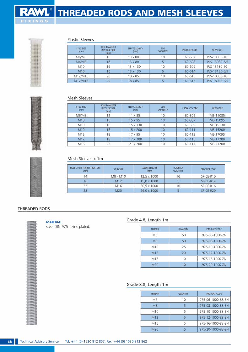
68 Technical Advisory Service Tel: +44 (0) 1530 812 857, Fax: +44 (0) 1530 812 862
Mesh Sleeves x 1m
HOLE DIAMETER IN STRUCTURE (mm) STUD SIZE SLEEVE LENGTH
(mm)BOX/PACK QUANTITY PRODUCT CODE
14 M8 - M10 12,5 x 1000 10 SP-CE-R1016 M12 15,0 x 1000 5 SP-CE-R1222 M16 20,5 x 1000 10 SP-CE-R1628 M20 26,0 x 1000 5 SP-CE-R20
Mesh Sleeves
Plastic Sleeves
STUD SIZE(mm)
HOLE DIAMETER IN STRUCTURE
(mm)
SLEEVE LENGTH (mm)
BOX QUANTITY PRODUCT CODE NEW CODE
M6/M8 16 13 x 80 10 60-607 PLS-13080-10M6/M8 16 13 x 80 5 60-608 PLS-13080-5/5
M10 16 13 x 130 10 60-609 PLS-13130-10M10 16 13 x 130 5 60-614 PLS-13130-5/5
M12/M16 20 18 x 85 10 60-615 PLS-18085-10M12/M16 20 18 x 85 5 60-616 PLS-18085-5/5
STUD SIZE(mm)
HOLE DIAMETER IN STRUCTURE
(mm)
SLEEVE LENGTH (mm)
BOX QUANTITY PRODUCT CODE NEW CODE
M6/M8 12 11 x 85 10 60-805 MS-11085M10 16 15 x 95 10 60-807 MS-15095M10 16 15 x 130 10 60-809 MS-15130M10 16 15 x 200 10 60-111 MS-15200M12 18 17 x 95 10 60-113 MS-17095M12 18 17 x 200 10 60-115 MS-17200M16 22 21 x 200 10 60-117 MS-21200
THREADED RODS AND MESH SLEEVES
THREADED RODS
MATERIAL steel DIN 975 - zinc plated.
THREAD QUANTITY PRODUCT CODE
M6 50 975-06-1000-ZN
M8 50 975-08-1000-ZN
M10 25 975-10-1000-ZN
M12 20 975-12-1000-ZN
M16 10 975-16-1000-ZN
M20 10 975-20-1000-ZN
Grade 4.8, Length 1m
THREAD QUANTITY PRODUCT CODE
M6 10 975-06-1000-88-ZN
M8 5 975-08-1000-88-ZN
M10 5 975-10-1000-88-ZN
M12 5 975-12-1000-88-ZN
M16 5 975-16-1000-88-ZN
M20 5 975-20-1000-88-ZN
Grade 8.8, Length 1m
RAWL_KATALOG_2007_2008.indb 68RAWL_KATALOG_2007_2008.indb 68 2007-10-15 14:37:232007-10-15 14:37:23

69Technical Advisory Service e-mail: [email protected] OR [email protected]
NUTS & WASHERS
Product Information
FLAT STANDARD WASHERS DIN 125
MATERIAL Low carbon steel, electro zinc plated.
PROPERTIES e Made in accordance with DIN 125.
DESCRIPTION DIMMENSION(mm)
QUANTITYPRODUCT CODE
BOX OUTER
M6 6.4 x 12.0 x 1.6 500 24000 VMM-125-06-ZN
M8 8.4 x 16.0 x 1.6 250 12000 VMM-125-08-ZN
M10 10.5 x 20.0 x 2.0 250 6000 VMM-125-10-ZN
M12 13.0 x 24.0 x 2.5 100 4800 VMM-125-12-ZN
M16 17.0 x 30.0 x 3.0 75 1800 VMM-125-16-ZN
M20 21.0 x 37.0 x 3.0 50 1200 VMM-125-20-ZN
FLAT LARGE WASHERS DIN 9021
MATERIAL Low carbon steel, electro zinc plated.
PROPERTIES e Made in accordance with DIN 9021.
DESCRIPTION DIMMENSION(mm)
QUANTITYPRODUCT CODE
BOX OUTER
M6 6.4 x 18.0 x 1.6 250 12000 VMM-9021-06-ZN
M8 8.4 x 24.0 x 2.0 200 4800 VMM-9021-08-ZN
M10 10.5 x 30.0 x 2.5 100 2400 VMM-9021-10-ZN
M12 13.0 x 37.0 x 3.0 100 1200 VMM-9021-12-ZN
M16 17.0 x 50.0 x 3.0 50 600 VMM-9021-16-ZN
M20 21.0 x 60.0 x 4.0 25 300 VMM-9021-20-ZN
HEXAGONAL STANDARD NUTS DIN 934
MATERIAL Low carbon steel, electro zinc plated.
PROPERTIES e Made in accordance with DIN 934.
DESCRIPTIONQUANTITY
PRODUCT CODEBOX OUTER
M6 250 12000 VMM-934-06-ZN
M8 250 6000 VMM-934-08-ZN
M10 250 3000 VMM-934-10-ZN
M12 150 1800 VMM-934-12-ZN
M16 100 900 VMM-934-16-ZN
M20 50 450 VMM-934-20-ZN
COUPLING NUT
DESCRIPTIONFor connecting multiple lengths of threaded rod.
MATERIAL Low carbon steel, electro zinc plated.
PROPERTIESMade in accordance with DIN 6334
THREAD NUT LENGTH (mm)
QUANTITYPRODUCT CODE
PACK OUTER
M6 18.0 500 2000 6334-06-1000-ZN
M8 24.0 250 1000 6334-08-1000-ZN
M10 30.0 125 500 6334-10-1000-ZN
M12 36.0 75 300 6334-12-1000-ZN
M16 48.0 40 160 6334-16-1000-ZN
M20 60.0 20 80 6334-20-1000-ZN
RAWL_KATALOG_2007_2008.indb 69RAWL_KATALOG_2007_2008.indb 69 2007-10-15 14:37:272007-10-15 14:37:27

70 Technical Advisory Service Tel: +44 (0) 1530 812 857, Fax: +44 (0) 1530 812 862
DESCRIPTIONTruly universal plug which fixes into any wall, ceiling or floor.
SUITABLE FOR USE IN:ConcreteBrickworkStoneBlockworkPlasterboardEtc
TILED WALLS Not suitable for use with 10 mm grey plugs. Always use smallest gauge screw to prevent possibility of cracking the tile.
FEATURES1. Unique design with expansion
throughout the length of the plug.2. Expands at the top giving
instant grip.3. Anti rotation features prevent
spinning in the hole.
Product Information
UNO™ UNIVERSAL PLUGFOR CONCRETE, BRICK, BLOCK & STONE ETC
TYPICAL APPLICATIONSe Shelving and cabinetse Suspended ceilingse Switch boxese Trunking and cable trayse Boilerse Water heaters & radiators
UNO™
DESCRIPTION SCREW RANGE(mm)
PLUG LENGTH(mm)
HOLE DIAMETER(mm)(do )
BOX/PACK QUANTITY
OUTERQUANTITY OPTIONS
PRODUCT CODENEW CODE
CLIP TUB BAG BOX
Yellow 3.0 - 4.5 24 5
96 10 — 68-500 UNO-YEL-96-C24 10 With screws 68-505 UNO-YEL-S-24-T
24 10With screws
and drill68-510 UNO-YEL-SD-24-T
1000 1 — 68-507 UNO-YEL-1000
Red 3.5 - 5.0 28 6
48 10 — 68-515 UNO-RED-48-C96 10 — 68-520 UNO-RED-96-C
288 20 — 68-525 UNO-RED-28848 10 With drill 68-530 UNO-RED-D-48-T
24 10With screws
and drill68-535 UNO-RED-SD-24-T
24 10 With screws 68-540 UNO-RED-S-24-T1000 1 — 68-517 UNO-RED-1000
Brown 4.0 - 6.0 30 7
48 10 — 68-555 UNO-BRN-48-C96 10 — 68-560 UNO-BRN-96-C
288 20 — 68-565 UNO-BRN-28848 10 With screws 68-570 UNO-BRN-D-48-T
24 10With screws
and drill68-575 UNO-BRN-SD-24-T
24 10 With screws 68-580 UNO-BRN-S-24-T1000 1 — 68-557 UNO-BRN-1000
Blue 4.5 - 6.0 32 8
80 10 — 68-595 UNO-BLU-80-C10 10 With coach screws 68-600 UNO-BLU-CS-10-T
10 10With coach screws
and drill68-605 UNO-BLU-CSD-10-T
1000 1 — 68-597 UNO-BLU-1000
Grey 5.0 - 8.0 36 1080 10 — 68-615 UNO-GRY-80-C
1000 1 — 68-617 UNO-GRY-1000Mixed Red/Brown/Blue
3.5 - 6.0 28/30/32 6/7/860 10 — 68-630 UNO-MIX-272-T
272 20 — 68-635 UNO-MIX-272
5 mm Nylon
3.0 - 4.5 24 550 10 — 68-640 UNO-N-05-10/50
100 10 — 68-645 UNO-N-0550 10 With screws 68-650 UNO-N-05-S-50
6 mm Nylon
3.5 - 5.0 28 650 10 — 68-655 UNO-N-06-10/50
100 10 — 68-660 UNO-N-0650 10 With screws 68-665 UNO-N-06-S-50
8 mm Nylon
4.5 - 6.0 32 850 10 — 68-670 UNO-N-08-10/50
100 10 — 68-675 UNO-N-0850 10 With screws 68-680 UNO-N-08-CS-50
10 mm Nylon
5.0 - 8.0 36 1050 10 — 68-685 UNO-N-10-10/50
100 20 — 68-690 UNO-N-1025 10 With screws 68-695 UNO-N-10-CS-25
RAWL_KATALOG_2007_2008.indb 70RAWL_KATALOG_2007_2008.indb 70 2007-10-15 14:37:342007-10-15 14:37:34

71Technical Advisory Service e-mail: [email protected] OR [email protected]
Speci� cation Data
UNO™ UNIVERSAL PLUGFOR CONCRETE, BRICK, BLOCK & STONE ETC
MATERIALSCREW
SIZE(mm)
MAXIMUM SAFE WORKING LOAD (kg)5 mmNYLON
6 mmNYLON
8 mmNYLON
10 mmNYLON
YELLOW RED BROWN BLUE GREY
30 N/mm2
CONCRETE
3.5 33 274 58 47
4.5 81 63 59 385 83 75 55
5.5 95 806 113 125 757 1468 247
CONCRETEHOLLOW CORE
BEAM
3 283.5 314 35 36
4.5 41 455 48 50 516 58 58 608 68
20.5 N/mm2
BRICK
3 233.5 36 314 53 55 43
4.5 70 75 54 455 95 68 60
5.5 83 88 706 100 118 807 1008 125
PERFORATED BRICKWORK
3 153.5 204 25 30
4.5 36 455 43 55 506 65 70 638 85
2.8 N/mm2
BLOCKWORK
3 63.5 74 8 9
4.5 10 125 12 14 156 17 18 198 22
3.5 N/mm2
BLOCKWORK
3 83.5 94 10 11
4.5 13 155 15 18 196 22 23 248 28
MATERIALSCREW
SIZE(mm)
MAXIMUM SAFE WORKING LOAD (kg)5 mmNYLON
6 mmNYLON
8 mmNYLON
10 mmNYLON
YELLOW RED BROWN BLUE GREY
HOLLOW 7 N/mm2
BLOCKWORK
3 183.5 214 24 28
4,5 33 385 38 43 456 48 50 538 58
1 5 N/mm2
BLOCKWORK
3 163,5 25 224 37 39 30
4,5 49 53 38 325 67 47 42
5,5 58 61 496 70 82 567 708 88
HOLLOWCLAY POT
3 133,5 154 16 18
4,5 20 235 21 25 266 26 28 298 30
9.5 mmPLASTERBOARD
3,5 7 74 8 8 8
4,5 9 9 95 10 10 9
5,5 10 10 106 10 11
12.5 mmPLASTERBOARD
3 93,5 94 9 9
4,5 10 105 10 10 116 11 11 118 13
2.5 mmPLYWOOD
3 93,5 94 9 9
4,5 10 105 10 11 116 11 11
1. Solid Walls.Drill hole to suit screw length. Clean out hole.
2. Insert plug and tap flush to surface. Place item to be fixed. Insert screw and tighten.
3. Combination Walls (install as diagram 2).
3. Hollow Walls.Drill hole, insert plug and tap flush to surface. Place item to be fixed, insert screw and tighten.
Installation
RAWL_KATALOG_2007_2008.indb 71RAWL_KATALOG_2007_2008.indb 71 2007-10-15 14:38:092007-10-15 14:38:09

72 Technical Advisory Service Tel: +44 (0) 1530 812 857, Fax: +44 (0) 1530 812 862
FIX™ EXPANSION PLUGFOR CONCRETE, BRICK, STONE ETC.
MATERIALPlug sleeve:polyamide PA 6.0 (Nylon) or impact resistant co-polymer of polypropylene PPScrew:electro-zinc coated steel ~10 �m
SUITABLE FOR USE IN:ConcreteBrickConcrete BlockworkStoneEtc.
Product Information
TYPICAL APPLICATIONSe Shelving and cabinetse Suspended ceilingse Switch boxese Trunking and cable trayse Boilerse Water heaters & radiators
HOLE DIAMETER(mm)(do)
PLUGLENGTH
(mm)
BOX/PACKQUANTITY
OUTERQUANTITY PRODUCT CODE
5 25 100 9600 FIX-N-05
6 30 100 4800 FIX-N-06
8 40 100 2400 FIX-N-08
10 50 100 2400 FIX-N-10
12 60 50 1200 FIX-N-12
14 70 25 600 FIX-N-14
FIX - EXPANSION PLUGS
HOLE DIAMETER(mm)(do)
PLUGLENGTH
(mm)
SCREWDIMENSIONS
(mm)
PACKQUANTITY
OUTERQUANTITY PRODUCT CODE
10 50 6.0 x 60 100 1200 FIX-10/660
12 60 8.0 x 70 50 600 FIX-12/70
WITH COACH SCREW
HOLE DIAMETER(mm)(do)
PLUG LENGTH
(mm)
BOX/PACKQUANTITY
OUTERQUANTITY PRODUCT CODE
6 30 100 4800 FIX-NF-06
8 40 100 2400 FIX-NF-08
10 50 100 2400 FIX-NF-10
12 60 50 1200 FIX-NF-12
14 70 25 600 FIX-NF-14
FIX - EXPANSION PLUGS WITH COLLAR
Installation
HOLE DIAMETER(mm)(do)
PLUG LENGTH
(mm)
SCREWDIMENSIONS
(mm)
PACKQUANTITY
OUTERQUANTITY PRODUCT CODE
5 25 3.5 x 30 100 4800 FIX-05+
6 30 3.5 x 40 100 4800 FIX-06+340
8 40 5.0 x 45 100 2400 FIX-08+
8 40 5.0 x 60 100 2400 FIX-08+560
WITH COUNTERSUNK HEAD SCREWWITH POZIDRIVE
RAWL_KATALOG_2007_2008.indb 72RAWL_KATALOG_2007_2008.indb 72 2007-10-15 14:38:162007-10-15 14:38:16

73Technical Advisory Service e-mail: [email protected] OR [email protected]
WITH ANGLE HOOK
HOLE DIAMETER(mm)(do)
PLUG LENGTH(mm)
HOOKDIMENSIONS
(mm)
PACKQUANTITY
OUTERQUANTITY
PRODUCT CODE
6 30 4.5 x 35 100 2400 FIX-06K
8 40 5.0 x 50 100 1200 FIX-08K
10 50 6.0 x 55 100 1200 FIX-10K
12 60 8.0 x 65 50 600 FIX-12K
HOLE DIAMETER(mm)(do)
PLUG LENGTH(mm)
HOOKDIMENSIONS
(mm)
PACKQUANTITY
OUTERQUANTITY
PRODUCT CODE
6 30 4.5 x 50 100 2400 FIX-06S
8 40 5.0 x 65 100 1200 FIX-08S
10 50 6.0 x 85 100 1200 FIX-10S
WITH ROUND HOOK
HOLE DIAMETER(mm)(do)
PLUG LENGTH(mm)
HOOKDIMENSIONS
(mm)
PACKQUANTITY
OUTERQUANTITY
PRODUCT CODE
12 60 8.0 x 130 25 600 FIX-12H
WITH PIG TAIL HOOK
Product Information
FIX™ EXPANSION PLUGFOR CONCRETE, BRICK, STONE ETC.
RAWL_KATALOG_2007_2008.indb 73RAWL_KATALOG_2007_2008.indb 73 2007-10-15 14:38:242007-10-15 14:38:24

74 Technical Advisory Service Tel: +44 (0) 1530 812 857, Fax: +44 (0) 1530 812 862
STAIR-TREAD FIXINGSFOR CONCRETE, STEEL
MATERIALPlug sleeve:polyamide PA 6.0 (Nylon) Screw:electro-zinc coated steel ~10 �m Washer:polypropylene
CONTENTS OF SET:expansion plugcountersunk head screw,4 levelling washers
Product Information
CENTRE PUNCHES FOR STAIR TREADS
STAIR-TREAD FIXINGS FOR INSTALLATION ON CONCRETE STAIRCASE STRINGERS
STAIR-TREAD FIXINGS FOR INSTALLATION ON STEEL STAIRCASE STRINGERS
S1
L1 L2
S2
Installation in concrete
Installation in hollow steel construction
L1 L2
S1
S2
MATERIALPlug sleeve:polyamide PA 6.0 (Nylon) Screw:electro-zinc coated steel ~10 �m Washer:polypropylene
CONTENTS OF SET:expansion plugcountersunk head screw,4 levelling washers
S1(mm)
L1(mm)
S2(mm)
L2(mm)
PACKQUANTITY
OUTERQUANTITY PRODUCT CODE
14 22 8 40 25 600 LSB
S1(mm)
L1(mm)
S2(mm)
L2(mm)
PACKQUANTITY
OUTERQUANTITY PRODUCT CODE
14 20 9 10 25 600 LSM
S2(mm)
PACKQUANTITY PRODUCT CODE
8,0 2 LSB-P
9,0 2 LSM-P
RAWL_KATALOG_2007_2008.indb 74RAWL_KATALOG_2007_2008.indb 74 2007-10-15 14:38:282007-10-15 14:38:28

75Technical Advisory Service e-mail: [email protected] OR [email protected]
DOOR STOPS BALL SHAPED
L2
S2
Product Information
Installation
MATERIALPlug sleeve:polyamide PA 6.0 (Nylon) Screw:electro-zinc coated steel ~10 �m Door stop: polyethylene with vinyl acetate
CONTENTS OF SET:expansion plugcountersunk head screw,ball-shaped door stop
S2(mm)
L2(mm)
COLOR OF THE BALL
PACKQUANTITY
OUTERQUANTITY PRODUCT CODE
8 40 white 15 180 FIX-ODBK-01
8 40 beige 15 180 FIX-ODBK-02
8 40 brown 15 180 FIX-ODBK-03
8 40 black 15 180 FIX-ODBK-04
8 40 grey 15 180 FIX-ODBK-05
RAWL_KATALOG_2007_2008.indb 75RAWL_KATALOG_2007_2008.indb 75 2007-10-15 14:38:322007-10-15 14:38:32

76 Technical Advisory Service Tel: +44 (0) 1530 812 857, Fax: +44 (0) 1530 812 862
PLASTIC PLUGSFOR BRICKWORK & CONCRETE
Product Information
TYPICAL APPLICATIONSe Fixing central heating
pipes, shelving, brackets,dado rails and otherwoodwork.
e Securing light wall unitsand kitchen fittings.
DESCRIPTIONAll purpose cost effective fixing for medium and lightweight applications.
SUITABLE FOR USE IN:BrickworkConcrete
FEATURES1. Profiled Body for extra grip.2. Anti-rotation fins.3. Three colour coded sizes for
screws from 3-6 mm (No. 4-14).
4. Additional sizes for screws 3-10 mm (No. 4-20).
PLASTIC PLUGS
DESCRIPTIONSCREWRANGE(mm)
PLUGLENGTH
(mm)
HOLE DIAMETER
(mm)(do)
OPTIONS BOX/PACK QUANTITY
PRODUCT CODE
NEW CODECLIPPACKS BOX
CARDED UNCARDED
YELLOW3.0 - 5.0
No. 4 - 1025 5
20 67-128 YEL-20-NC100 67-125 YEL-100-NC100 67-126 YEL-100-C300 67-900 YEL-3001000 67-910 YEL-1000
RED3.5 - 5.5
No. 6 - 1235 6
20 67-138 RED-20-NCwith drill 50 67-300 RED-10/50+D
100 67-130 RED-100-NC100 67-134 RED-100-C300 67-902 RED-3001000 67-913 RED-1000
BROWN5.0 - 6.0
No. 10 - 1445 7
20 67-237 BRN-20-NCwith drill 50 67-310 BRN-10/50+D
100 67-231 BRN-100-NC100 67-233 BRN-100-C
with drill 100 67-315 BRN-10/100+D300 67-904 BRN-3001000 67-916 BRN-1000
ASSORTED yel-low, red, brown
3.0 - 6.0No 4 - 14 25 - 45 5 - 7 300 67-905 AST
GREEN 3.0 - 4,5No. 4 - 8 20 4.5 10 x 10 67-008 PLP-GRN
PINK 3.5 - 5.0No. 6 - 10 25 5.5 10 x 10 67-012 PLP-PNK
0RANGE 4.5 - 5.5No. 8 - 12 25 6.5 10 x 10 67-016 PLP-ORG
GREY 4.5 - 5.0No. 8 - 10 35 5.5 10 x 10 67-020 PLP-GRY
WHITE 4.5 - 5.5No. 10 - 14 35 6.5 10 x 10 67-024 PLP-WHT
BLUE 5.0 - 6.0No. 10 - 14 35 8.0 10 x 10 67-028 PLP-BLU
RED 4.5 - 5.0No. 8 - 10 35 5.5 10 x 10 67-021 PLP-RED
BROWN 5.0 - 6.0No. 10 - 14 35 8.0 10 x 10 67-029 PLP-BRN
YELLOW 8.0 - 10.0No. 16 - 20 50 11 10 x 10 67-032 PLP-YEL
BROWN 5.0 - 6.0No. 10 - 14 35 8.0 22 x 50 67-965 PLP-22
BROWN 5.0 - 6.0No. 10 - 14 35 8.0 44 x 50 67-960 PLP-44
2 1
RAWL_KATALOG_2007_2008.indb 76RAWL_KATALOG_2007_2008.indb 76 2007-10-15 14:38:352007-10-15 14:38:35

77Technical Advisory Service e-mail: [email protected] OR [email protected]
MATERIAL SCREW SIZE(mm)
MAXIMUM RECOMMENDED LOAD (kg)
YELLOW (5 mm) RED (6 mm) BROWN (7 mm)
20 N/mm2
Brick
3.0 17
3.5 26 34
4.0 43 55
4.5 55 60
5.0 68 68 64
5.5 85 83
6.0 100
30 N/mm2
Concrete
3.0 21
3.5 30 43
4.0 51 68
4.5 68 72
5.0 81 75
5.5 100
6.0 115
Installation
1. Mark out and drill holes. 2. Clean out holes and insert plastic plug. Tap home.
3. Position fixture, insert screw. Tighten until fixture is secure.
Product Information
Plastic Plug Performance Data
PLASTIC PLUGSFOR BRICKWORK & CONCRETE
RAWL_KATALOG_2007_2008.indb 77RAWL_KATALOG_2007_2008.indb 77 2007-10-15 14:38:402007-10-15 14:38:40

78 Technical Advisory Service Tel: +44 (0) 1530 812 857, Fax: +44 (0) 1530 812 862
RAWL-IN-ONE™ MULTI-PURPOSE PLUGFOR HOLLOW, SOLID & COMBINATION WALLS
Product Information
TYPICAL APPLICATIONSe Perfect for household
fixtures, cupboards, small shelves, hooks etc.
e Hollow walls– plasterboard, plywood, chipboard etc.Sizes 5 & 6mm only.
e Solid walls–brickwork, blockwork, concrete etc. All plug sizes.
e Combination walls–dry lined walls etc. All plug sizes.
DESCRIPTIONThe all-purpose plug which accepts a variety of screw sizes.
SUITABLE FOR USE IN:Hollow, Solid & Combination Walls.
FEATURES1. Flange ensures flush fit
to surface. Can be collapsed for deep setting in solid materials.
2. Anti-rotation fins prevent spinning when tightening screw.
3. Engineered grip feature for extra holding power.
4. Twin expansion points for a strong fix in hollow, solid or combination materials
Rawl-in-One™ Multi-purpose Plug Performance Data
1
2
3
4
4
RAWL-IN-ONE™ Multi-purpose Plug
DESCRIPTIONPLUG
DIAMETER(mm)
SCREWRANGE(mm)
HOLE DIAMETER (do)
OPTIONS PACK/CLIP QUANTITY
CLIP 48 PCSSOLID SUBSTRATES
(mm)
HOLOW & COMBINATION SUBSTARTES
(mm)PRODUCT CODES NEW CODES
Mixed48 pcs
53.0 - 5.0
(No 4 - 10)5 4.5
carded
8
67-614 RIO-48-C6
3.5 - 5.5(No 6 - 12)
6 5.5 20
84.5 - 6.0
(No 8 - 10)8 7 16
105.0 - 8.0
(No 4 - 10)10 9 4
MATERIALMAXIMUM RECOMMENDED LOAD
5 mm 6 mm 8 mm 10 mm
7 N/mm2 Blockwork (Solid) 20 kg 25 kg 30 kg 40 kg
7 N/mm2 Blockwork (Solid) 25 kg 30 kg 35 kg 50 kg
InstallationCombination
walls
Hollow walls
1. Mark out and drill holes. 2. Clean out holes and insert Rawl-in-One™plug. Tap home.
3. Position fixture, insert screw. Tighten until fixture is secure.
Solid walls
RAWL_KATALOG_2007_2008.indb 78RAWL_KATALOG_2007_2008.indb 78 2007-10-15 14:39:162007-10-15 14:39:16

79Technical Advisory Service e-mail: [email protected] OR [email protected]
HDPE PLASTIC PLUGFOR CONCRETE, BLOCKS, SOLID & HOLLOW BRICK, LOW DENSITY MATERIALS
TYPICAL APPLICATIONSe For fixings of light weight
loads e.g. switches, sockets, conduits trunking, skirtings and frames, junction boxes etc.
SUITABLE FOR USE IN:Concrete, Stone/Rock,Solid Bricks & Blocks,Low Density Materials,Holow Bricks,Building Blocks,Board Materials.
HDPE PLASTIC PLUG
DESCRIPTION DRILL DIAMETER(mm) SCREW GAUGE PLUG LENGTH
(mm) BOX QUANTITY OUTER QUANTITY PRODUCT CODE
RED 5.5, 6.0 6, 8 & 10 34 100 1000 67-200
BROWN 7 8, 10, 12 & 14 40 100 1000 67-602
YELLOW 5, 5.5 4, 6 & 8 22 100 1000 67-603
Installation
1. Mark out and drill holes. 2. Clean out holes and insert plastic plug. Tap home.
3. Position fixture, insert screw. Tighten until fixture is secure.
DESCRIPTION PRODUCT CODE BOXQUANTITY
LIST PRICE PER BOX
LIST PRICE PER 100
GROUP DISCOUNT CODE
mm pcs £ £
6 x 32 KGS-0632 200 45.00 22.50 B-CP-A41
8 x 38 KGS-0838 200 55.80 27.90 B-CP-A41
8 x 60 KGS-0860 100 29.90 29.90 B-CP-A41
10 x 60 KGS-1060 100 34.45 34.45 B-CP-A41
LIGHTWEIGHT BLOCK ANCHOR
Steel fixing giving good performance in light weight blocks such as aerated and loght aggregate blocks.
RAWL_KATALOG_2007_2008.indb 79RAWL_KATALOG_2007_2008.indb 79 2007-10-15 14:39:292007-10-15 14:39:29

80 Technical Advisory Service Tel: +44 (0) 1530 812 857, Fax: +44 (0) 1530 812 862
SANITARY FIXINGSFOR CONCRETE, BRICK, BLOCK & STONE
Product Information
DESCRIPTIONA dedicated range of fixings, designed for secure mounting of all types of Sanitary Ware into solid substrates.
SUITABLE FOR USE IN:Concrete, Brick, Block,Stone.
WC OR BIDET LATERAL FIXING SET
Installation
Installation
CORNER BASIN FIXING SET
HOLE DIAMETER IN SUBSTRATES
(mm)PRODUCT CODE NEW CODE
8 mm 67-482 R-STY-CB
HOLE DIAMETER IN SUBSTRATES
(mm)PRODUCT CODE NEW CODE
10 mm 67-448 R-STY-PB
RAWL_KATALOG_2007_2008.indb 80RAWL_KATALOG_2007_2008.indb 80 2007-10-15 14:39:472007-10-15 14:39:47

81Technical Advisory Service e-mail: [email protected] OR [email protected]
SANITARY FIXINGS
WASHBASIN FIXINGS
WC-FIXINGS
CONTENTS OF SET: 2 expansion plugs, 2 stud screws, 2 nuts, 2 off-centre washers, 2 cover caps.
CONTENTS OF SET: 2 expansion plugs, 2 snap-fit sleeves,2 hexagonal head screws, 2 cover caps.
Product Information
MATERIALPlug sleeve: impact resistant copolymer of polypropylene PP or polyamide PA 6.0 (Nylon) Screw: electro-zinc coated steel ~10 �mOff-centre washer and masking cap: polypropylene
SUITABLE FOR USE IN:Concrete, Brick, Block,Stone.
Installation
HOLE DIAMETER(mm)(do)
PLUG DESCRIPTION SCREW DESCRIPTION
COLOUROF COVER
CAPS
QUANTITY PRODUCT CODEPACK OUTER
10 10 x 50 6,0 x 80 white 1 500 KPM100
10 10 x 50 6,0 x 80 silver 1 500 KPM100S
10 10 x 50 6,0 x 80 alumin. 1 500 KPM100A
10 10 x 50 6,0 x 80 gold 1 500 KPM100Z
Installation
HOLE DIAMETER(mm)(do)
PLUG DESCRIPTION SCREW DESCRIPTION
COLOUROF COVER
CAPS
QUANTITYPRODUCT CODE
PACK OUTER
10 10 x 50 M8 x 80
white
1 125 KPU100
12 12 x 60 M8 x 100 1 100 KPU120
12 12 x 60 M8 x 120 1 75 KPU140
14 14 x 70 M10 x 140 1 65 KPU141
10 10 x 50 M8 x 80
silver
1 125 KPU100A
12 12 x 60 M8 x 100 1 100 KPU120A
12 12 x 60 M8 x 120 1 75 KPU140A
14 14 x 70 M10 x 140 1 65 KPU141A
10 10 x 50 M8 x 80
alumin.
1 125 KPU100S
12 12 x 60 M8 x 100 1 100 KPU120S
12 12 x 60 M8 x 120 1 75 KPU140S
14 14 x 70 M10 x 140 1 65 KPU141S
10 10 x 50 M8 x 80
gold
1 125 KPU100Z
12 12 x 60 M8 x 100 1 100 KPU120Z
12 12 x 60 M8 x 120 1 75 KPU140Z
14 14 x 70 M10 x 140 1 65 KPU141Z
FOR CONCRETE, BRICK, BLOCK & STONE
RAWL_KATALOG_2007_2008.indb 81RAWL_KATALOG_2007_2008.indb 81 2007-10-15 14:39:552007-10-15 14:39:55

82 Technical Advisory Service Tel: +44 (0) 1530 812 857, Fax: +44 (0) 1530 812 862
FRAME FIXING
Product Information
TYPICAL APPLICATIONSe Quick, easy fixing of timber
or metal door and window frames.
e No marking out - drill straight through frame.
DESCRIPTIONFixing timber or metal window and door frames.
SUITABLE FOR USE IN:Concrete, Stone, Brickwork & Blockwork.
FEATURES1. Countersunk Pozi-head screw
provided, suitable for use with screw caps.
2. Durable PA6 grade nylon for extended fixing life.3. Tough nylon sleeve prevents
frame distortion during tightening.
4. Anti-rotation lugs.5. Extended zig-zag design for enhanced expansion.
FRAME FIXINGS
DESCRIPTION SCREWHEAD TYPE(mm)
HOLE DIAMETER(mm)(do)
MAX FIXTURE THICKNESS
(mm)(T� x)
QUANTITYPRODUCT CODE
NEW CODEPACK BOX
8 x 60 Countersunk Pozi 3 8 2016 21-357 FF-08060/1650 21-320 FF-08060
8 x 80 Countersunk Pozi 3 8 40
4 21-373 FF-08080/046 + drill 21-358 FF-08080/06-D
16 21-350 FF-08080/1650 21-323 FF-08080
8 x 100 Countersunk Pozi 3 8 6016 21-351 FF-08100/1650 21-326 FF-08100
8 x 120 Countersunk Pozi 3 8 8016 21-352 FF-08120/1650 21-329 FF-08120
10 x 80 Countersunk Pozi 4 10 3012 21-371 FF-10080/1250 21-335 FF-10080
10 x 100 Countersunk Pozi 4 10 50
4 21-383 FF-10100/046 + drill 21-360 FF-10100/06-D
12 21-366 FF-10100/1250 21-338 FF-10100
10 x 120 Countersunk Pozi 4 10 70
4 21-390 FF-10120/0412 21-367 FF-10120/1216 21-354 FF-10120/1650 21-340 FF-10120
10 x 135 Countersunk Pozi 4 10 854 21-393 FF-10135/0412 21-368 FF-10135/1250 21-344 FF-10135
10 x 160 Countersunk Pozi 4 10 11012 21-369 FF-10160/1250 21-347 FF-10160
MATERIALMAXIMUM SAFE WORKING LOAD
TENSION TENSION8 mm 10 mm
Blockwork 7 N/mm2 80 kg 100 kg
Brick 20 N/mm2 100 kg 120 kg
Concrete 30 N/mm2 125 kg 150 kg
Frame Fixing Performance Data
FOR CONCRETE, STONE, BRICKWORK & BLOCKWORK
RAWL_KATALOG_2007_2008.indb 82RAWL_KATALOG_2007_2008.indb 82 2007-10-15 14:40:112007-10-15 14:40:11

83Technical Advisory Service e-mail: [email protected] OR [email protected]
Installation
1. Place frame in position and drill appropriate diameter hole through frame and into base material.
The hole depth (including frame) should equal plug length plus 10mm.
Clean out hole. Countersink for neat finish.
2. Insert plug through fixture into hole and lightly tap until flush with the surface.
3. Insert the screw and tighten until secure.
Product Information
FRAME FIXINGS WITH LONG EXPANSION ZONEWITH COACH SCREW
HOLE DIAMETER(mm)(do)
SCREWQUANTITY
PRODUCT CODEPACK OUTER
10 6,8x85/13 50 600 KD-1008010 6,8x10⁵/13 25 450 KD-1010010 6,8x125/13 25 300 KD-1012010 6,8x145/13 25 300 KD-1014010 6,8x165/13 25 300 KD-1016010 6,8x205/13 25 300 KD-1020010 6,8x245/13 25 300 KD-10240
FRAME FIXINGS WITH LONG EXPANSION ZONEWITH COUNTERSUNK HEAD SCREW
HOLE DIAMETER(mm)(do)
SCREWQUANTITY
PRODUCT CODEPACK OUTER
8 4,8x65/Pozi3 100 1200 KKS-080608 4,8x85/Pozi3 50 600 KKS-080808 4,8x10⁵/Pozi3 50 600 KDS-081008 4,8x125/Pozi3 50 600 KDS-081208 4,8x145/Pozi3 50 600 KDS-0814010 6,8x85/Pozi4 50 600 KDS-1008010 6,8x10⁵/Pozi4 25 450 KDS-1010010 6,8x125/Pozi4 25 300 KDS-1012010 6,8x145/Pozi4 25 300 KDS-1014010 6,8x165/Pozi4 25 300 KDS-1016010 6,8x205/Pozi4 25 300 KDS-1020010 6,8x245/Pozi4 25 300 KDS-10240
FRAME FIXINGS WITH LONG EXPANSION ZONEWITH COACHSCREW AND WASHER
HOLE DIAMETER(mm)(do)
SCREWQUANTITY
PRODUCT CODEPACK OUTER
16 11,8x145/19 20 200 KD-1614016 11,8x165/19 20 200 KD-1616016 11,8x205/19 20 200 KD-1620016 11,8x245/19 20 200 KD-16240
4. Fit a screw cap when fixing is complete (optional).
FRAME FIXINGFOR CONCRETE, STONE, BRICKWORK & BLOCKWORK
FRAME FIXINGS WITH LONG EXPANSION ZONEWITH COUNTERSUNK TORX HEAD SCREW
HOLE DIAMETER(mm)(do)
SCREWQUANTITY
PRODUCT CODEPACK OUTER
10 6,8x85/Torx40 50 600 KDT-1008010 6,8x10⁵/Torx40 25 450 KDT-1010010 6,8x125/Torx40 25 300 KDT-1012010 6,8x145/Torx40 25 300 KDT-1014010 6,8x165/Torx40 25 300 KDT-1016010 6,8x205/Torx40 25 300 KDT-10200
BASE MATERIAL PRODUCT TYPERECOMMENDED LOAD CAPACITY (kN)
8mm 10mm 16mm
CONCRETE C20/25 KK* 0.6 1,0SOLID BRICK KK* 0.4 0.9
AERATED CONCRETE KD* 0.5 0.6 1.4HOLLOW BRICK KD* 0.3 0.7 1.1
CLAY BLOCK KD* 0.4 0.7
RAWL_KATALOG_2007_2008.indb 83RAWL_KATALOG_2007_2008.indb 83 2007-10-15 14:40:132007-10-15 14:40:13

84 Technical Advisory Service Tel: +44 (0) 1530 812 857, Fax: +44 (0) 1530 812 862
PLUG DESCRIPTIONHOLE DIAMETER
(mm)(do)
SCREWHEAD TYPE
QUANTITYPRODUCT CODE
PACK OUTER
5 x 25 5 Pozi2 100 2400 FX-N-05L025
5 x 30 5 Pozi2 100 2400 FX-N-05L030
5 x 35 5 Pozi2 100 2400 FX-N-05L035
5 x 40 5 Pozi2 100 2400 FX-N-05L040
5 x 50 5 Pozi2 100 2400 FX-N-05L050
6 x 30 6 Pozi2 100 2400 FX-N-06L030
6 x 35 6 Pozi2 100 2400 FX-N-06L035
6 x 40 6 Pozi2 100 2400 FX-N-06L040
6 x 45 6 Pozi2 100 1800 FX-N-06L045
6 x 50 6 Pozi2 100 1800 FX-N-06L050
6 x 55 6 Pozi2 100 1800 FX-N-06L055
6 x 60 6 Pozi2 100 1200 FX-N-06L060
6 x 70 6 Pozi2 100 1200 FX-N-06L070
6 x 80 6 Pozi2 100 1200 FX-N-06L080
8 x 45 8 Pozi2 100 1200 FX-N-08L045
8 x 60 8 Pozi2 100 1200 FX-N-08L060
8 x 80 8 Pozi2 50 600 FX-N-08L080
8 x 100 8 Pozi2 50 600 FX-N-08L100
8 x 120 8 Pozi2 50 600 FX-N-08L120
8 x 140 8 Pozi2 50 600 FX-N-08L140
8 x 160 8 Pozi2 50 600 FX-N-08L160
10 x 100 10 Pozi3 25 300 N-10L100
10 x 120 10 Pozi3 25 300 N-10L120
10 x 140 10 Pozi3 25 300 N-10L140
FOR CONCRETE, BRICK, BLOCKWORK, STONE
TYPICAL APPLICATIONSe Fixing stud battens to
walls before cladding.e Fixing long runs of shelf
supports.e Fixing skirting boards to
walls.
DESCRIPTIONFor fast, repetitive fixing with minimal screwdriver work.
SUITABLE FOR USE IN:Concrete,Blockwork,Stone,Sandstone, Etc.
MATERIAL Plug sleeve: impact resistant co-polymer of polypropylene PP or polyamide PA 6.0 (Nylon). Nail: steel electro-zinc coated ~10 �m.
FEATURES1. Reinforced screwhead - facilitates
high knock-in loads with the added benefit of plug neck grip.
2. Hammer in drive screw for fast installation.
3. Deforming crumple zone allows quick adjustment in uneven surfaces.
4. Extended expansion zone gives extra grip.
Product Information
HAMMER FIXINGS, COUNTERSUNK HEAD WITH STEEL NAIL
HAMMER FIXINGS
HAMMER FIXINGS CYLINDER HEAD WITH STEEL NAIL
PLUG DESCRIPTION
HOLE DIAMETER(mm)(do)
FLANGEDIAMETER
(mm)
SCREWHEAD TYPE
QUANTITYPRODUCT CODE
PACK OUTER
5 x 25 5 8 Pozi2 100 2400 FX-N-05C025
5 x 30 5 8 Pozi2 100 2400 FX-N-05C030
5 x 35 5 8 Pozi2 100 2400 FX-N-05C035
5 x 40 5 8 Pozi2 100 2400 FX-N-05C040
5 x 50 5 8 Pozi2 100 2400 FX-N-05C050
6 x 30 6 10 Pozi2 100 2400 FX-N-05C030
6 x 35 6 10 Pozi2 100 2400 FX-N-06C035
6 x 40 6 10 Pozi2 100 2400 FX-N-06C040
6 x 45 6 10 Pozi2 100 1800 FX-N-06C045
6 x 55 6 10 Pozi2 100 1800 FX-N-06C055
6 x 60 6 10 Pozi2 100 1200 FX-N-06C060
6 x 70 6 10 Pozi2 100 1200 FX-N-06C070
6 x 80 6 10 Pozi2 100 1200 FX-N-06C080
8 x 45 8 12 Pozi2 100 1200 FX-N-08C045
8 x 60 8 12 Pozi2 100 1200 FX-N-08C060
8 x 80 8 12 Pozi2 50 600 FX-N-08C080
8 x 100 8 12 Pozi2 50 600 FX-N-08C100
8 x 120 8 12 Pozi2 50 600 FX-N-08C120
Installation
RAWL_KATALOG_2007_2008.indb 84RAWL_KATALOG_2007_2008.indb 84 2007-10-15 14:40:242007-10-15 14:40:24
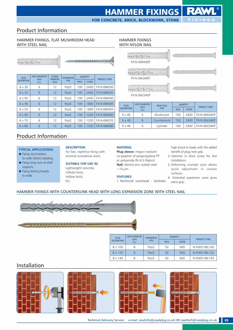
85Technical Advisory Service e-mail: [email protected] OR [email protected]
HAMMER FIXINGSFOR CONCRETE, BRICK, BLOCKWORK, STONE
HAMMER FIXINGS WITH NYLON NAIL
HAMMER FIXINGS, FLAT MUSHROOM HEAD WITH STEEL NAIL
PLUG DESCRIPTION
HOLE DIAMETER(mm)(do)
FLANGEDIAMETER
(mm)
SCREWHEAD TYPE
QUANTITYPRODUCT CODE
PACK OUTER
6 x 30 6 12 Pozi2 100 2400 FX-N-06K030
6 x 35 6 12 Pozi2 100 2400 FX-N-06K035
6 x 40 6 12 Pozi2 100 2400 FX-N-06K040
6 x 45 6 12 Pozi2 100 1800 FX-N-06K045
6 x 55 6 12 Pozi2 100 1800 FX-N-06K055
6 x 60 6 12 Pozi2 100 1200 FX-N-06K060
6 x 70 6 12 Pozi2 100 1200 FX-N-06K070
6 x 80 6 12 Pozi2 100 1200 FX-N-06K080
FX-N-06L040P
FX-N-06C040P
PLUG DESCRIPTION
HOLE DIAMETER(mm)(do)
HEAD PLUG TYPE
QUANTITYPRODUCT CODE
PACK OUTER
6 x 40 6 Mushroom 100 2400 FX-N-06K040P
6 x 40 6 Countersunk 100 2400 FX-N-06L040P
6 x 40 6 Cylinder 100 2400 FX-N-06C040P
Product Information
FX-N-06K040P
Installation
TYPICAL APPLICATIONSe Fixing stud battens
to walls before cladding.e Fixing long runs of shelf
supports.e Fixing skirting boards
to walls.
Product Information
DESCRIPTIONFor fast, repetitive fixing with minimal screwdriver work.
SUITABLE FOR USE IN:Lightweight concrete, Cellular brick, Hollow brick,Etc.
MATERIAL Plug sleeve: impact resistant co-polymer of polypropylene PP or polyamide PA 6.0 (Nylon). Nail: electro-zinc coated steel ~10 �m.
FEATURES1. Reinforced screwhead - facilitates
high knock-in loads with the added benefit of plug neck grip.
2. Hammer in drive screw for fast installation.
3. Deforming crumple zone allows quick adjustment in uneven surfaces.
4. Extended expansion zone gives extra grip.
HAMMER FIXINGS WITH COUNTERSUNK HEAD WITH LONG EXPANSION ZONE WITH STEEL NAIL
PLUG DESCRIPTION
HOLE DIAMETER(mm)(do)
SCREWHEAD TYPE
QUANTITYPRODUCT CODE
PACK OUTER
8 x 100 8 Pozi2 50 600 N-KWD-08L100
8 x 120 8 Pozi2 50 600 N-KWD-08L120
8 x 140 8 Pozi2 50 600 N-KWD-08L140
RAWL_KATALOG_2007_2008.indb 85RAWL_KATALOG_2007_2008.indb 85 2007-10-15 14:40:302007-10-15 14:40:30

86 Technical Advisory Service Tel: +44 (0) 1530 812 857, Fax: +44 (0) 1530 812 862
PVCu FRAME FIXINGFOR CONCRETE, STONE, BRICKWORK & BLOCKWORK
Product Information
TYPICAL APPLICATIONSe Rapid installation of new
PVCu double glazing units.e Secure fixings for PVCu and
aluminium replacement frames.
e Fixing clips into reinforced and unreinforced PVCu frames for extra support.
DESCRIPTIONDirect mounting of PVCu window frames to solid brickwork and masonry.
SUITABLE FOR USE IN:Concrete, Stone, Brickwork & Blockwork.
NB. Not suitable for hollow brickwork.
FEATURES1. Locking tabs clip into the PVCu
frame.2. Durable PA6 nylon sleeve for
extended fixing life.3. Design prevents frame
distortion when tightening.
DESCRIPTION
HOLE DIAMETERIN STRUCTURE
(mm)(do)
HOLE DIAMETERIN FIXTURE
(mm)
MAX FIXTURETHICKNESS
(mm)QUANTITY PACK BOX
8 x 100 8 9 35 100 21-650
8 x 140 8 9 75 100 21-652
10 x 100 10 11 35 100 21-656
10 x 120 10 11 55 16 21-625
10 x 120 10 11 55 100 21-658
10 x 140 10 11 75 16 21-627
PVCu FRAME FIXING
PVCu FRAME FIXING Performance Data
MATERIALMAXIMUM SAFE WORKING LOAD TENSION AND SHEAR
8 mm 10 mm
7 N/mm2 Blockwork 50 kg 70 kg
20 N/mm2 Brick 60 kg 80 kg
30 N/mm2 Concrete 100 kg 130 kg
1. Place frame in position and drill through section at manufacturer’s recommended centres.
2. Drill through frame holes into base material to required depth, using appropriate size of masonry drill. Total hole depth (incl. frame) should equal fixing length plus 10mm.
3. Clean hole and install fixing through frame into masonry. Tighten screw until secure. Fixing may be released and re-secured, if necessary, to align frame accurately. Fit a screw cap when fixing is complete (optional).
Installation
RAWL_KATALOG_2007_2008.indb 86RAWL_KATALOG_2007_2008.indb 86 2007-10-15 14:40:452007-10-15 14:40:45

87Technical Advisory Service e-mail: [email protected] OR [email protected]
METAL FRAME FIXING
Product Information
TYPICAL APPLICATIONSe Fixes door and window
frames to most types of building material.
e Easy fixing for metal-framed doors and windows.
e Perfect for installing patio doors.
DESCRIPTIONFor distortion-free installation of metal frames.No marking out - fixes straight through the fixture into the substrate.
SUITABLE FOR USE IN:Concrete, Stone, Brickwork & Blockwork.
NB. Not suitable for hollow brickwork.
FEATURES1. Anti-rotation lugs prevent
rotation during tightening.2. All-steel construction for
strength and durability.3. Metal sleeve design avoids
frame distortion during tightening up.
METAL FRAME FIXINGS
Installation
DESCRIPTION SCREWHEAD TYPE
HOLE DIAMETERIN STRUCTURE
(mm)(do)
HOLE DIAMETERIN FIXTURE
(mm)QUANTITY PRODUCT CODE NEW CODE
10 x 72 Pozi 3 10 11 100 21-100 O-10072
10 x 92 Pozi 3 10 11 100 21-101 O-10092
10 x 112 Pozi 3 10 11 100 21-102 O-10112
10 x 132 Pozi 3 10 11 100 21-104 O-10132
10 x 152 Pozi 3 10 11 100 21-106 O-10152
10 x 182 Pozi 3 10 11 100 21-108 O-10182
10 x 202 Pozi 3 10 11 100 O-10202
MASKING CAPS FOR METAL FRAME FIXINGS
CAP DIAMETER(mm)
QUANTITY PRODUCT CODEPACK OUTER
15 100 1000 KO-BIALY/WHT
15 100 1000 KO-BRAZ/BRN
1. Pre-drill the frame with an 11mm HSS twist drill.
2. Place frame in position and drill through frame holes into base material to required depth, using recommended masonry drill.
Total hole depth (incl. frame) should equal length of fixing plus 10 mm.
3. Clean hole and install fixing through frame into masonry.
Tighten screw until secure. Fixing may be released and resecured, if necessary, to align frame accurately.
METAL FRAME FIXINGS Performance Data
MATERIAL MAXIMUM RECOMMENDED LOADTENSION (kg)
20 N/mm2 Brick 120
30 N/mm2 Concrete 170
FOR CONCRETE, STONE, BRICKWORK & BLOCKWORK
4. Fit masking cup.
RAWL_KATALOG_2007_2008.indb 87RAWL_KATALOG_2007_2008.indb 87 2007-10-15 14:40:532007-10-15 14:40:53

88 Technical Advisory Service Tel: +44 (0) 1530 812 857, Fax: +44 (0) 1530 812 862
CONCRETE FRAME SCREWS
Product Information
TYPICAL APPLICATIONSe Door and window framese Securing formworke M & E instalatione Suspended ceilingse Lightweight steel angles
MATERIALhardened steel, electro-zinc coated ~10 �m
SUITABLE FOR USE IN:Pre-drilled Ø 6mm: concrete, full and hollow brick, clinker brick, stone, structural clay tile. Without pre-drilling: aerated concrete, timber.
INSTALLATION TIPSMinimum screw anchorage depth: for dense building materials -
30 mm, for aerated concrete and timber - 60 mm.
FEATURES1. No expansion force therefore
imposes less stress on substrate during installation.
2. Small hole diameter giving high loads.
3. Easily removed for temporary works.
Installation
Concrete Frame Screw With Cylinder Head
DESCRIPTION HOLE DIAMETER(do)
SCREWHEAD TYPE QUANTITY PRODUCT
CODE
7.5 x 52 6.0 Torx 25 100 WHS-75052
7.5 x 72 6.0 Torx 25 100 WHS-75072
7.5 x 92 6.0 Torx 25 100 WHS-75092
7.5 x 112 6.0 Torx 25 100 WHS-75112
7.5 x 132 6.0 Torx 25 100 WHS-75132
7.5 x 152 6.0 Torx 25 100 WHS-75152
7.5 x 182 6.0 Torx 25 100 WHS-75182
Concrete Frame Screw With Countersunk Head
DESCRIPTION HOLE DIAMETER(do)
SCREWHEADTYPE QUANTITY PRODUCT
CODE
7.5 x 52 6.0 Torx 30 100 WHO-75052
7.5 x 72 6.0 Torx 30 100 WHO-75072
7.5 x 92 6.0 Torx 30 100 WHO-75092
7.5 x 112 6.0 Torx 30 100 WHO-75112
7.5 x 132 6.0 Torx 30 100 WHO-75132
7.5 x 152 6.0 Torx 30 100 WHO-75152
7.5 x 182 6.0 Torx 30 100 WHO-75182
1. Pre-drilled Ø 6mm in concrete, full and hollow brick, clinker brick, stone, structural clay tile. 2. Without pre-drilling in aerated concrete, timber.
Concrete Frame Screw Performance Data
BASE MATERIAL CHARACTERISTIC LOAD CAPACITY *(kN)
RECOMMENDED LOAD CAPACITY * (kN)
Concrete C20/25 5.1 1.7
Solid Brick 2.1 0.7
Aerated Concrete 1.1 0.4
Hollow Brick 0.9 0.3
BASE MATERIALPREDRILLED HOLE
DIAMETER(mm)
MINIMUM FIXTURE DEPTH(mm)
MINIMUM HOLE DEPTH(mm)
Concrete C20/25 6 30 40
Solid Brick, Hollow Brick 6 60 70
Aerated Concrete — 60 70
* Recommended load capacity for shear and tension.
FOR CONCRETE, STONE, BRICKWORK & BLOCKWORK
RAWL_KATALOG_2007_2008.indb 88RAWL_KATALOG_2007_2008.indb 88 2007-10-15 14:40:582007-10-15 14:40:58

89Technical Advisory Service e-mail: [email protected] OR [email protected]
DESCRIPTIONHOLE DIAMETER
(mm)(do)
HOLE DEPTH(Inclusive of Fixture
Thickness)(mm)
QUANTITY
BOX
PRODUCT CODE NEW CODE
6 x 40 6 45 200 21-240 EXP-06040
6 x 50 6 55 100 21-242 EXP-06050
6 x 60 6 65 100 21-244 EXP-06060
6 x 80 6 85 100 21-246 EXP-06080
8 x 70 8 75 100 21-258 EXP-08070
8 x 90 8 95 100 21-260 EXP-08090
8 x 110 8 115 100 21-262 EXP-080110
8 x 130 8 135 100 21-264 EXP-080130
Product Information
RAWL R-EXP ANCHOR
DESCRIPTIONFast, economical through fixing for securing timber and metal profiles to solid brickwork and masonry.No marking out or screwing required, simply hammers through fixture into pre-drilled hole.
SUITABLE FOR USE IN:Concrete, Stone, Brickwork & Blockwork.
FEATURES1. Collar holds fixture firmly in place, no screw
required.2. Spring steel anchor expands along its full length
to provide a secure fixing.
Installation
1. Drill hole trough fixture and into substrate. Clean out debris.
2. Insert anchor. 3. Hammer until flush to surface.
1
2
FOR CONCRETE, STONE, BRICKWORK & BLOCKWORK
LOADING DIRECTION
PRODUCT DIAMETER
EMBEDMENT DEPTH(mm)
ULTIMATE PERFORMANCE
(kN)
SAFE WORKING
LOAD(kN)
TENSION
6mmREDUCED 30 1.6 0.3
STANDARD 45 3.2 0.6
8mmREDUCED 40 4.0 0.8
STANDARD 60 6.8 1.4
SHEAR
6mmREDUCED 30 4.0 1.0
STANDARD 45 7.0 1.8
8mmREDUCED 40 9.0 2.3
STANDARD 60 14.0 3.5
PRODUCT SIZEMAXIMUM FIXTURE THICKNESS
(mm)
STANDARD REDUCED
6 x 40 - 10
6 x 50 5 20
6 x 60 15 30
6 x 80 35 50
8 x 70 10 30
8 x 90 30 50
8 x 110 50 70
8 x 130 70 90
8 x 150 90 110
INSTALLATION
PERFORMANCE (CONCRETE C20/25)
RAWL_KATALOG_2007_2008.indb 89RAWL_KATALOG_2007_2008.indb 89 2007-10-15 14:41:042007-10-15 14:41:04

90 Technical Advisory Service Tel: +44 (0) 1530 812 857, Fax: +44 (0) 1530 812 862
DRYWALL SCREWS
Drywall Screws Black Phosphate
APPLICATIONMainly in drywall systems for fixing plasterboards to metal framing.
MATERIAL Low-carbon steel-black phosphate coating.
PROPERTIESe Bugle Head Philips2.
SCREW SIZE(mm)
SCREWHEAD TYPE
BOX/PACK QUANTITY
(pcs)
OUTERQUANTITY
(pcs)PRODUCT CODE
3.5 x 25 Philips2 1000 18000 FS-3525
3.5 x 32 Philips2 1000 12000 FS-3532
3.5 x 38 Philips2 1000 12000 FS-3538
3.5 x 42 Philips2 500 6000 FS-3542
3.5 x 50 Philips2 500 6000 FS-3550
4.2 x 60 Philips2 250 3000 FS-4260
4.2 x 75 Philips2 250 3000 FS-4275
SCREW SIZE(mm)
SCREWHEAD TYPE
BOX/PACK QUANTITY
(pcs)
OUTERQUANTITY
(pcs)PRODUCT CODE
3.5 x 25 Philips2 1000 18000 FT-3525
3.5 x 32 Philips2 1000 12000 FT-3532
3.5 x 38 Philips2 1000 12000 FT-3538
3.5 x 42 Philips2 500 6000 FT-3542
3.5 x 50 Philips2 500 6000 FT-3550
4.2 x 60 Philips2 250 3000 FT-4260
4.2 x 75 Philips2 250 3000 FT-4275
Coarse Thread For Timber Fine Thread For Sheet Metal
APPLICATIONMainly in drywall systems for fixing plasterboards to wooden framing.
MATERIAL Low-carbon steel-black phosphate coating.
PROPERTIESe Bugle Head Philips2.
Drywall Collated Screws Black Phosphate
APPLICATIONMainly in drywall systems for fixing plasterboards to wooden metal framing.
MATERIAL Low-carbon steel-black phosphate coating.
PROPERTIESe Bugle Head Philips2.
SCREW SIZE(mm)
SCREWHEAD TYPE
PIECES PER STRIPE
BOX/PAX QUANTITY
(pcs)
OUTERQUANTITY
(pcs)PRODUCT CODE
3.5 x 25 Philips2 50 1000 10000 FTC-3525
3.5 x 35 Philips2 50 1000 10000 FTC-3535
3.5 x 38 Philips2 50 1000 10000 FTC-3538
3.5 x 45 Philips2 50 500 10000 FTC-3545
3.5 x 50 Philips2 50 500 10000 FTC-3550
3.5 x 55 Philips2 50 250 10000 FTC-3555
Coarse Thread For Timber
SCREW SIZE(mm)
SCREWHEAD TYPE
PIECES PER STRIPE
BOX/PACK QUANTITY
(pcs)
OUTERQUANTITY
(pcs)PRODUCT CODE
3.5 x 25 Philips2 50 1000 10000 FSC-3525
Coarse Thread For Timber
RAWL_KATALOG_2007_2008.indb 90RAWL_KATALOG_2007_2008.indb 90 2007-10-15 14:41:092007-10-15 14:41:09

91Technical Advisory Service e-mail: [email protected] OR [email protected]
SELF-DRILLING/ DECKING SCREWS
SCREW SIZE(mm)
SCREWHEAD TYPE
BOX/PACK QUANTITY
(pcs)
OUTERQUANTITY
(pcs)PRODUCT CODE
3,5 x 25 Philips2 1000 18000 WS-3525
3,5 x 32 Philips2 1000 12000 WS-3532
3,5 x 38 Philips2 1000 12000 WS-3538
3,5 x 42 Philips2 500 6000 WS-3542
3,5 x 50 Philips2 500 6000 WS-3550
3,5 x 60 Philips2 250 3000 WS-3560
SCREW SIZE(mm)
SCREWHEAD TYPE
BOX/PAX QUANTITY
(pcs)
OUTER QUANTITY
(pcs)PRODUCT CODE
3,5 x 9,5 Philips2 1000 24000 WS-35953,9 x 11 Philips2 1000 24000 WS-3911
APPLICATION Mainly for joining metal supporting profiles in drywall systems.
MATERIALLow carbon steel.PROPERTIESe Drilling capacity (drill tip length)
up to 2.0 mm.
Phosphate Coating
SCREW SIZE(mm)
SCREWHEAD TYPE
BOX/PACK QUANTITY
(pcs)
OUTER QUANTITY
(pcs)PRODUCT CODE
3,5 x 9,5 Philips2 1000 24000 WS-3595-OC3,9 x 11 Philips2 1000 24000 WS-3911-OC
Zinc Plated min. 6 �m.
Self-Drilling Jackpoint Screws
Countersunk Head Black Phosphate
APPLICATION Mainly for fixing plasterboard to light gauge steel constructions over 0.7 mm.
MATERIALLow-carbon steel-black phosphate coating.
PROPERTIESe Drilling capacity (drill tip length)
up to 1.2 mm.
Pan Head
Decking Screws
APPLICATION Recommended for All Outdoor Uses with all Timber.
MATERIALHigh grade steel high-tech organic coating.
PROPERTIESe High-tech organic coating
offering exceptional resistance to corrosions, should last in axcess of 25 years.
e Tested under 1500 hours of salt spray, which under normal atmosferic conditions, should last in excess of 25 years.
e Coarse threaded for effective cutting into tanalized timber board.
e Double-angled countersunk head Pozi2 to ensure high strength fixing by increased torsional strength.
SCREW SIZE(mm)
SCREWHEAD TYPE
BOX/PACK QUANTITY(pcs) PRODUCT CODE
4.0 x 50 Pozi2 500 DS-4050
4.0 x 60 Pozi2 350 DS-4060
5.0 x 50 Pozi2 400 DS-5050
5.0 x 60 Pozi2 300 DS-5060
5.0 x 80 Pozi2 200 DS-5080
RAWL_KATALOG_2007_2008.indb 91RAWL_KATALOG_2007_2008.indb 91 2007-10-15 14:41:142007-10-15 14:41:14

92 Technical Advisory Service Tel: +44 (0) 1530 812 857, Fax: +44 (0) 1530 812 862
METAL SELF DRILLFOR PLASTERBOARD
TYPICAL APPLICATIONSe Securing wall and ceiling
fittings, installing hooks and brackets etc.
e Fixing electrical boxes, sanitary ware, cable trunking etc.
e Installing shelving units and wooden battens.
DESCRIPTIONNo drill required–simply pierce paper skin and screw home.Can be used in single and double thickness plasterboard.Ideal for use with either a power or standard Pozi Driv screwdriver.Must only be used with screws provided.
SUITABLE FOR USE IN:Plasterboard.
FEATURES1. Flange prevents accidental push
through in plasterboard.2. Short length ideally suited for
dry-lined walls.
METAL SELF-DRILL
PRODUCTLENGTH
(mm)SCREW TYPE SCREW SIZE
(mm)
MAX FIXTURE THICKNESS
(mm)(T� x)
QUANTITYPRODUCT CODE
NEW CODEPACK BOX
27 Panhead 4.5 x 20 10
6 07-105 DRIVA-02-4520/6
12 07-115 DRIVA-02-4520/12
25 07-120 DRIVA-02-4520-025
25 07-122 DRIVA-02-4520/25
50 07-124 DRIVA-02-4520/50
100 07-123 DRIVA-02-4520/100
100 07-125 DRIVA-02-4520
27 Panhead 4.5 x 35 25100 07-130 DRIVA-02-4535
100 07-132 DRIVA-02-4535/100
MATERIAL MAXIMUM RECOMMENDED LOAD TENSION OR SHAER
Plasterboard 9.5mm 6 kg
Plasterboard 12.5mm 8 kg
Metal Self-Drill Performance Data
Installation
1. Position the fixture and mark out holes. Using a No. 2 Pozi Driv screwdriver or screwdriver bit, push firmly into the board until thread engages.
2. Maintaining a firm pressure, screw in fixing until flush with the base material.
3. Place fixture in position, insert screw and tighten until secure.
Product Information
RAWL_KATALOG_2007_2008.indb 92RAWL_KATALOG_2007_2008.indb 92 2007-10-15 14:41:202007-10-15 14:41:20

93Technical Advisory Service e-mail: [email protected] OR [email protected]
NYLON SELF-DRILLFOR PLASTERBOARD
Product Information
TYPICAL APPLICATIONSe Ideal for installation
of sockets, light switches and other electrical fittings.
PLASTERBOARD FIXINGS
MATERIALPlug sleeve: PA 6.0+30 GF (polyamide reinforced with fibre glass - 30%).
SUITABLE FOR USE IN:Plasterboard,Gypsum fibreboard
INSTALLATION TIPS recommended screw diameter: 3,5 - 4,2 mm.
Installation
PLUG DESCRIPTION SCREW DESCRIPTIONQUANTITY
PRODUCT CODEPACK OUTER
14 x 35 4,2 x 32/Pozi2 100 1800 DRIVA-01PLUS
PLUG DESCRIPTIONQUANTITY
PRODUCT CODEPACK OUTER
14 x 35 100 1800 DRIVA-01
PLASTERBOARD FIXINGS WITH PANHEAD SCREW
RAWL_KATALOG_2007_2008.indb 93RAWL_KATALOG_2007_2008.indb 93 2007-10-15 14:41:232007-10-15 14:41:23
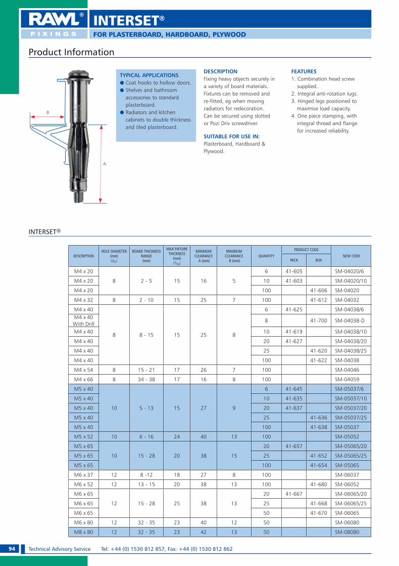
94 Technical Advisory Service Tel: +44 (0) 1530 812 857, Fax: +44 (0) 1530 812 862
INTERSET®
Product Information
TYPICAL APPLICATIONSe Coat hooks to hollow doors.e Shelves and bathroom
accessories to standard plasterboard.
e Radiators and kitchen cabinets to double thickness and tiled plasterboard.
DESCRIPTIONFixing heavy objects securely in a variety of board materials.Fixtures can be removed and re-fitted, eg when moving radiators for redecoration.Can be secured using slotted or Pozi Driv screwdriver.
SUITABLE FOR USE IN:Plasterboard, Hardboard & Plywood.
FEATURES1. Combination head screw
supplied.2. Integral anti-rotation lugs.3. Hinged legs positioned to
maximise load capacity.4. One piece stamping, with
integral thread and flange for increased reliability.
A
B
INTERSET®
DESCRIPTIONHOLE DIAMETER
(mm)(do)
BOARD THICKNESS RANGE(mm)
MAX FIXTURE THICKNESS
(mm)(T� x)
MINIMUM CLEARANCE
A (mm)
MINIMUM CLEARANCE
B (mm)QUANTITY
PRODUCT CODE
NEW CODEPACK BOX
M4 x 20
8 2 - 5 15 16 5
6 41-605 SM-04020/6
M4 x 20 10 41-603 SM-04020/10
M4 x 20 100 41-606 SM-04020
M4 x 32 8 2 - 10 15 25 7 100 41-612 SM-04032
M4 x 40
8 8 - 15 15 25 8
6 41-625 SM-04038/6M4 x 40With Drill
8 41-700 SM-04038-D
M4 x 40 10 41-619 SM-04038/10
M4 x 40 20 41-627 SM-04038/20
M4 x 40 25 41-620 SM-04038/25
M4 x 40 100 41-622 SM-04038
M4 x 54 8 15 - 21 17 26 7 100 SM-04046
M4 x 66 8 34 - 38 17 16 8 100 SM-04059
M5 x 40
10 5 - 13 15 27 9
6 41-645 SM-05037/6
M5 x 40 10 41-635 SM-05037/10
M5 x 40 20 41-637 SM-05037/20
M5 x 40 25 41-636 SM-05037/25
M5 x 40 100 41-638 SM-05037
M5 x 52 10 6 - 16 24 40 13 100 SM-05052
M5 x 65
10 15 - 28 20 38 15
20 41-657 SM-05065/20
M5 x 65 25 41-652 SM-05065/25
M5 x 65 100 41-654 SM-05065
M6 x 37 12 8 -12 18 27 8 100 SM-06037
M6 x 52 12 13 - 15 20 38 13 100 41-680 SM-06052
M6 x 65
12 15 - 28 25 38 13
20 41-667 SM-06065/20
M6 x 65 25 41-668 SM-06065/25
M6 x 65 50 41-670 SM-06065
M6 x 80 12 32 - 35 23 40 12 50 SM-06080
M8 x 80 12 32 - 35 23 42 13 50 SM-08080
FOR PLASTERBOARD, HARDBOARD, PLYWOOD
RAWL_KATALOG_2007_2008.indb 94RAWL_KATALOG_2007_2008.indb 94 2007-10-15 14:41:272007-10-15 14:41:27

95Technical Advisory Service e-mail: [email protected] OR [email protected]
Interset® Performance Data
MATERIALMAXIMUM RECOMMENDED LOAD TENSION AND SHEAR
4 x 20 4 x 32 4 x 40 5 x 40 5 x 65 6 x 52
Plasterboard 9.5mm — 9 kg 10 kg 12 kg — —
Plasterboard 12.5mm — — 12 kg 14 kg 16 kg 18 kg
Hollow door 10 kg 12 kg — — — —
INTERSET®
FOR PLASTERBOARD, HARDBOARD, PLYWOOD
Product Information
INTERSET® WITH ANGLE HOOK
DESCRIPTIONHOLE DIAMETER
(mm)(do)
BOARD THICKNESS
RANGE(mm)
QUANTITYPRODUCT
CODEPACK OUTER
M4 x 55 8 4-10 100 1800 SM-04032K
INTERSET® WITH ROUND HOOK
DESCRIPTIONHOLE DIAMETER
(mm)(do)
BOARD THICKNESS
RANGE(mm)
QUANTITYPRODUCT
CODEPACK OUTER
M4 x 55 8 4-10 100 1800 SM-04032S
1. Drill a hole to appropriate size.
2. Insert the fixing into the hole. Tap in lightly, ensuring that the anti-rotation lugs penetrate the face of the base material.
3. Keeping a firm forward pressure tighten the screw to set the fixing in position and then remove the screw.
4. Position the fixture, insert the screw and tighten until secure.
Installation
A
B
SETTING TOOLS
DESCRIPTION QUANTITY PRODUCT CODE
Professional 1 AT-88RAWL
DIY 1 AT-88M
RAWL_KATALOG_2007_2008.indb 95RAWL_KATALOG_2007_2008.indb 95 2007-10-15 14:41:292007-10-15 14:41:29

96 Technical Advisory Service Tel: +44 (0) 1530 812 857, Fax: +44 (0) 1530 812 862
Radius
FOR PLASTERBOARD
SPRING TOGGLE
Product Information
TYPICAL APPLICATIONSe Installing overhead lights,
ceiling fans and other fixtures.
DESCRIPTIONCavity fixing with long threaded screw, ideal for double thickness plasterboard and large fixtures.
SUITABLE FOR USE IN:PlasterboardLathe and plasterPlywoodHardwood
FEATURES1. Machine screw for ease
of tightening.2. Heavy gauge material
for superior loads.3. Spreads load over wide area
for extra load capacity.4. Heavy gauge nut to prevent
stripping under load.
DESCRIPTIONHOLE DIAMETER
(mm)(do)
MAX FIXTURE THICKNESS
(mm)(T� x)
PRODUCT RADIUS(mm)
OPTIONS QUANTITYPRODUCT CODE
NEW CODEPACK BOX
M3 x 50 11 30
20
With screws 6 94-365 SPO-03050-10/6
M3 x 50 11 30 With screws 10 94-450 SPO-03050
M3 x 50 11 30 With screws 20 94-600 SPO-03050-5/20
M3 x 50 11 30 With screws 100 94-430 SPO-03050
M3 11 N/A No screws 100 94-400 SPO-03
M5 x 50 14 24
25
With screws 6 94-369 SPO-05050-10/6
M5 x 50 14 24 With screws 10 94-456 SPO-05050
M5 x 50 14 24 With screws 20 94-650 SPO-05050-5/20
M5 x 50 14 24 With screws 100 94-436 SPO-05050
M5 x 80 14 54
25
With screws 6 94-371 SPO-05080-10/6
M5 x 80 14 54 With screws 10 94-459 SPO-05080
M5 x 80 14 54 With screws 20 94-680 SPO-05080-5/20
M5 x 80 14 54 With screws 100 94-439 SPO-05080
M5 14 N/A No screws 100 94-406 SPO-05
M6 x 60 18 28
30
With screws 10 94-462 SPO-06060
M6 x 80 18 48 With screws 10 94-464 SPO-06080
M6 x 60 18 28 With screws 50 94-442 SPO-06060
M6 x 80 18 48 With screws 50 94-445 SPO-06080
M6 18 N/A No screws 50 94-410 SPO-06
SPRING TOGGLE
Spring Toggle Performance Data
MATERIALMAXIMUM RECOMMENDED LOAD
M3 M5 M6
Plasterboard 9.5mm 15 kg 16 kg 18 kg
Plasterboard 12.5mm 17 kg 18 kg 20 kg
RAWL_KATALOG_2007_2008.indb 96RAWL_KATALOG_2007_2008.indb 96 2007-10-15 14:41:342007-10-15 14:41:34

97Technical Advisory Service e-mail: [email protected] OR [email protected]
Installation
1. Drill a hole of the appropriate diameter.
2. Compress the ‘wings’ and push the fixing into the hole.
3. While tightening the screw, pull the fixture out from the wall or ceiling to prevent the ‘wings’ spinning freely.
Product Information
SPRING TOGGLE WITH EYE
SPRING TOGGLE WITH ROUND HOOK
SPRING TOGGLE WITH PAN HEAD METRIC SCREW
DESCRIPTIONHOLE DIAMETER
(mm)(do)
PACKQUANTITY
OUTERQUANTITY PRODUCT CODE
M4 x 50 14 50 900 SPO450
SPRING TOGGLEFOR PLASTERBOARD
DESCRIPTIONHOLE DIAMETER
(mm)(do)
PACKQUANTITY
OUTERQUANTITY PRODUCT CODE
M4 x 75 14 50 900 SPO475
DESCRIPTIONHOLE DIAMETER
(mm)(do)
PACKQUANTITY
OUTERQUANTITY PRODUCT CODE
M4 x 75 14 50 900 SPO475Z
RAWL_KATALOG_2007_2008.indb 97RAWL_KATALOG_2007_2008.indb 97 2007-10-15 14:41:372007-10-15 14:41:37

98 Technical Advisory Service Tel: +44 (0) 1530 812 857, Fax: +44 (0) 1530 812 862
FOR PLASTERBOARD
PLASTERBOARD PLUG
Product Information
DESCRIPTIONFor fixing to cavity walls and ceillings of low structural strength.
SUITABLE FOR USE IN:Plasterboard.
FEATURES1. Can be used with woodscrews
or selftapping screws.2. Flange holds fixing flush with
wall surface.3. Unique zig-zac design for
greater expansion and holding power within the plasterboard.
4. Wings provide clamping to back of plasterboard.
TYPICAL APPLICATIONSe Ideal for overhead fixings in
plasterboard, e.g. installing overhead lights.
e Installation electrical fitting on cavity walls.
PLASTERBOARD PLUG
1. Mark out and drill a 7 mm diameter hole.
2. Compress wings and push plug into hole. Lightly tap plug flush with surface.
3. Position fixture, insert 4.5 mm (No. 8) screw and tighten until secure.
Installation
HOLE DIAMETER(mm)
SCREW DIAMETER(mm) DESCRIPTION PRODUCT CODE
7.04.5 mm(No. 8)
Pack of 10 plugs 10-400
Pack of 25 plugs 10-402
Pack of 50 plugs 10-404
Pack of 50 plugs + 7mm drill 10-406
Pack of 100 plugs 10-408
Pack of 10 plugs + 7mm drill 10-410
RAWL_KATALOG_2007_2008.indb 98RAWL_KATALOG_2007_2008.indb 98 2007-10-15 14:41:412007-10-15 14:41:41

99Technical Advisory Service e-mail: [email protected] OR [email protected]
PLASTIC TOGGLEFOR PLASTERBOARD, HARDBOARD, PLYWOOD
PLASTIC TOGGLE
DESCRIPTIONMedium duty plasterboard fixing.Fixtures can be removed and replaced for redecoration.
SUITABLE FOR USE IN:Plasterboard,HardboardPlywood.
MATERIALPlug sleeve: impact resistant co-polymer of polypropylene Screw: electro-zinc coated steel ~10 �m
Product Information
TYPICAL APPLICATIONSe Securing bathroom
and kitchen fittings.e Installation of ceiling
fixtures, such as light fittings.
e Fixing light shelving, brackets and hooks.
DESCRIPTIONHOLE DIAMETER
(mm)(do)
BOARD THICKNESS
RANGE(mm)
QUANTITYPRODUCT CODE
PACK OUTER
4.0 x 50 10 9.5 100 1800 10G
PLASTIC TOGGLE WITH COUNTERSUNK HEAD SCREW POZI 2
DESCRIPTIONHOLE DIAMETER
(mm)(do)
BOARD THICKNESS
RANGE(mm)
QUANTITYPRODUCT CODE
PACK OUTER
4.0 x 60 10 9.5 100 1800 10GL
PLASTIC TOGGLE WITH ANGLE HOOK
DESCRIPTIONHOLE DIAMETER
(mm)(do)
BOARD THICKNESS
RANGE(mm)
QUANTITY PRODUCT CODEPACK OUTER
4.0 x 50 10 9.5 100 1800 10GK
Installation
PLASTIC TOGGLE
DESCRIPTIONHOLE DIAMETER
(mm)(do)
BOARD THICKNESS
RANGE(mm)
QUANTITY PRODUCT CODEPACK OUTER
3,5 x 45 8 12.5 100 1800 08GL
RAWL_KATALOG_2007_2008.indb 99RAWL_KATALOG_2007_2008.indb 99 2007-10-15 14:41:432007-10-15 14:41:43

100 Technical Advisory Service Tel: +44 (0) 1530 812 857, Fax: +44 (0) 1530 812 862
Product Information
RAWLNUT™ FLEXI-PLUGFOR VIRTUALLY ANY CONSTRUCTION MATERIAL
TYPICAL APPLICATIONSe Fixing to virtually any
material, either solid or hollow, eg metal sheet, plasterboard, plywood, glass, plastic, etc.
e Secure fixing in brittle or unknown substrates.
e Ideal for fixing in irregular or oversized holes.
DESCRIPTIONA problem solving fixing.
SUITABLE FOR USE IN:For use in virtually any hollow or solid construction material.
FEATURES1. Resistant to vibration and
corrosion.2. Flange holds fixing flush to wall
surface.3. Sleeve compresses to provide
secure fixing, even in irregular shaped holes.
4. Made from synthetic rubber for more severe conditions.
5. Bonded brass insert.
RAWLNUT™ Flexi-Plug
DESCRIPTION SCREW LENGTH(mm)
HOLE DIAMETER(mm)(do)
FLANGE THICKNESS
(mm)
LENGTH (mm)
GRIP RANGE (mm) QUANTITY
PRODUCT CODENEW CODE
PACK BOX
M3 (3240) 308 1.2 24 6 - 14
4 09-045 RNT-M3x30/4M3 (3240) 30 50 09-040 RNT-M3x30M4 (4100) 20
8 1,4 12,6 0 - 4 4 09-105 RNT-M4x20/4
M4 (4100) 20 50 09-100 RNT-M4x20M4 (4100) No screws 50 09-093 RNT-M4/12M4 (4240) 30
8 1,2 24 6 - 1450 09-130 RNT-M4x30
M4 (4240) No screws 50 09-123 RNT-M4/24M5 (5150) 20
10 1,3 14,1 0 - 550 09-195 RNT-M5x20
M5 (5150) No screws 50 09-184 RNT-M5/14M5 (5250) 30
10 1,3 26,1 8 - 164 09-240 RNT-M5x30/4
M5 (5250) 30 50 09-235 RNT-M5x30M5 (5250) No screws 50 09-224 RNT-M5/26M5 (5400) 50
10 1,3 39,8 20 - 3050 09-317 RNT-M5x40-50
M5 (5400) No screws 50 09-310 RNT-M5/40M6 (6150) No screws 13 1,3 16 0 - 3 50 09-355 RNT-M6/16M6 (6250) No screws 13 2 26,7 6 - 13 50 09-385 RNT-M6/27M6 (6350) No screws 13 1,3 35 11 - 23 50 09-415 RNT-M6/35M6 (6500) No screws 13 1,2 50 26 - 38 50 09-437 RNT-M6/50M8 (8250) No screws 16 5 27,9 4 - 10 50 09-473 RNT-M8/28M8 (8300) No screws 18 1,2 30 6 - 15 50 09-475 RNT-M8/30M8 (8500) No screws 18 2 50 15 - 39 50 09-533 RNT-M8/50M10 (1055) No screws 20 1,3 55 20 - 36 25 09-594 RNT-M10/55M12 (1275) No screws 24 1,3 80 30 - 50 20 09-654 RNT-M12/80
RAWLNUT™ Flexi-Plug Performance Data
MATERIALMAXIMUM RECOMMENDED LOAD
3240 4240 5250 5400 6250 8300 8500 1055 1275
Plasterboard 9.5 mm 8 kg 8 kg 9 kg 12 kg 13 kgPlasterboard 12.5 mm 10 kg 10 kg 11 kg 14 kg 18 kgBlockwork Solid 7 N/mm2 60 kg 100 kg 130 kgBlockwork Hollow 7 N/mm2 40 kg 65 kg 70 kgBlockwork Solid 3,5 N/mm2 30 kg 50 kg 60 kgBlockwork Hollow 3,5 N/mm2 20 kg 30 kg 40 kg
Installation
1. Drill appropriate diameter hole. For solid materials, drill hole to length of screw. Clean out hole and remove sharp edges to avoid damaging fixing.
2. Insert the fixing up to its flange.
3. Place fixture in position. Insert screw and tighten to compress sleeve and form a secure fixing.
Do not overtighten.
4. Works equally well in uniform or irregularly shaped holes.
RAWL_KATALOG_2007_2008.indb 100RAWL_KATALOG_2007_2008.indb 100 2007-10-15 14:41:552007-10-15 14:41:55
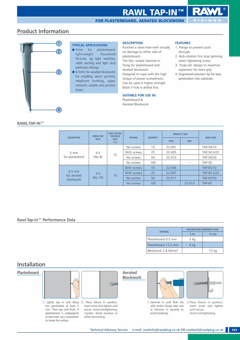
101Technical Advisory Service e-mail: [email protected] OR [email protected]
Product Information
TYPICAL APPLICATIONSe 5mm for plasterboard:
light-weight household fix-tures, eg light switches, cable ducting and light duty bathroom fittings.
e 6.5mm for aerated blockwork: for installing alarm sys-tems, telephone trunking, pipes, conduits, sockets and junction boxes.
DESCRIPTIONPunches a clean hole with virtually no damage to either side of plasterboard.The fast, simple hammer-in fixing for plasterboard and aerated blockwork.Designed to cope with the high torque of power screwdrivers. Can be used in higher strength block if hole is drilled first.
SUITABLE FOR USE IN:Plasterboard & Aerated Blockwork.
FEATURES1. Flange to prevent push
through.2. Anti-rotation fins stop spinning
when tightening screw.3. ‘Snap-set’ design to maximise
expansion for extra grip.4. Engineered precision tip for easy
penetration into substrate.
1
2
3
4
RAWL-TAP-IN™
RAWL TAP-IN™
DESCRIPTION SCREW SIZE(mm)
MAX FIXTURE THICKNESS
(mm)(T� x)
OPTIONS QUANTITYPRODUCT CODE
NEW CODEPACK BOX
5 mmfor plasterbord
4.5(No 8)
15
No screws 10 22-001 TAP-50/10
With screws 25 22-005 TAP-50-S/25
No screws 50 22-010 TAP-50/50
No screws 100 — TAP-50
6.5 mmfor aerated blockwork
5.0(No 10)
10
With screws 10 22-006 TAP-65/10
With screws 25 22-007 TAP-65-S/25
No screws 50 22-011 TAP-65/50
No screws 100 22-013 TAP-65
1. Lightly tap in until fixing has penetrated at least 5 mm. Then tap until flush. If plasterboard is wallpapered or skimmed, use a screwdriver to break the surface.
2. Place fixture in position, insert screw and tighten until secure. Avoid overtightening.
Caution: Avoid excessive or offset hammering.
1. Hammer in until flush (As with similar fixings take care to hammer in squarely to avoid breaking).
2. Place fixture in position, insert screw and tighten until secure.
Avoid overtightening.
InstallationAerated Blockwork
Plasterboard
Rawl-Tap-In™ Performance Data
MATERIALMAXIMUM RECOMMENDED LOAD
5 mm 6.5 mm
Plasterboard 9.5 mm 3 kg
Plasterboard 12.5 mm 4 kg
Blockwork 2.8 N/mm2 15 kg
FOR PLASTERBOARD, AERATED BLOCKWORK
RAWL_KATALOG_2007_2008.indb 101RAWL_KATALOG_2007_2008.indb 101 2007-10-15 14:41:592007-10-15 14:41:59

102 Technical Advisory Service Tel: +44 (0) 1530 812 857, Fax: +44 (0) 1530 812 862
HOLEBORE™FOR PLASTERBOARD, HARDBOARD & PLYWOOD
Product Information
TYPICAL APPLICATIONSe For use with most fixings
into plasterboard. e Small sizes also suitable for
use in thin plywood panels.
DESCRIPTION Fast, easy way to install fixings in plasterboard walls and ceilings.Eliminates the need for a drill and screwdriver. 5 blade sizes for most fixings requirements. Tool with interchangeable blades includes Pozi Driv and flat screwdriver head.
SUITABLE FOR USE IN:PlasterboardHardboardPlywood.
FEATURES1. Pierces plasterboard easily
and cleanly.2. Blade sizes for most
fixing requirements.
HoleBore™
DESCRIPTION OPTION QUANTITY PRODUCT CODES NEW CODE
Holebore 6 PC Blade Set 10 89-230 R-HB
Replacement Blade Set 10 89-232 R-HB-R
1. Using appropriate size for the fixing, push tip into substrate.
Apply even pressure whilst twisting clockwise and anti-clockwise until it passes through the substrate.
2. Insert fixing 3. Remove the blade from the HoleBore™ handle and replace with screwdriver bit provided.
4. Tighten until secure.
Installation
RAWL_KATALOG_2007_2008.indb 102RAWL_KATALOG_2007_2008.indb 102 2007-10-15 14:42:032007-10-15 14:42:03

103Technical Advisory Service e-mail: [email protected] OR [email protected]
DESCRIPTIONMainly for fixing lightweight ceilings and suspended ceilings to solid building materials.Fire resistant
SUITABLE FOR USE IN:Concrete, Masonry, Etc.
MATERIALsteel 4.6 - electro-zinc coated ~10 �m
Installation
PLUG DESCRIPTIONHOLE DIAMETER
(mm)(do)
QUANTITY PRODUCT CODE
8 x 42 8 100 Z-KSP
8 x 42 8 100 Z-KSP/F
CEILING WIRE HANGER
DESCRIPTIONMainly for fixing lightweight ceilings and suspended ceilings to solid building materials.Fire resistant
SUITABLE FOR USE IN:Concrete, Masonry, Etc.
MATERIALelectro-zinc coated steel.
Installation
CEILING SPRING PIN
Product Information
Product Information
PLUG DESCRIPTIONHOLE DIAMETER
(mm)(do)
QUANTITYPRODUCT CODE
PACK OUTER
6 x 63 6 100 2400 SRS-06063
TYPICAL APPLICATIONSe Lightweight suspended
ceilings.
TYPICAL APPLICATIONSe Lightweight suspended
ceilings.
CEILING HANGERSFOR CONCRETE & MASONRY
RAWL_KATALOG_2007_2008.indb 103RAWL_KATALOG_2007_2008.indb 103 2007-10-15 14:42:062007-10-15 14:42:06

104 Technical Advisory Service Tel: +44 (0) 1530 812 857, Fax: +44 (0) 1530 812 862
METAL HAMMER FIXINGSFOR CONCRETE & MASONRY
DESCRIPTIONFor light duty fixings of metal constructions and sheet metal to solid building materials
SUITABLE FOR USE IN:Concrete, Masonry, Etc.
MATERIALPlug sleeve: zamak (Zn-Al).Nail: electro-zinc coated steel ~10 �m.
Product Information
PLUG DESCRIPTIONHOLE DIAMETER
(mm)(do)
FLANGE DIAMETER(mm)
QUANTITYPRODUCT CODE
PACK OUTER
5 x 20 5 12 100 3600 KMW-05020
6 x 30 6 12 100 1800 KMW-06030
6 x 40 6 12 100 1200 KMW-06040
6 x 50 6 12 100 1200 KMW-06050
6 x 65 6 12 100 1200 KMW-06065
Product Information
Installation
DESCRIPTIONMainly for fixing lightweight ceilings and suspended ceilings to solid building materials.Fire resistant
SUITABLE FOR USE IN:Concrete, Masonry, Etc.
MATERIALsteel 4.6 - electro-zinc coated ~10 �m
Installation
PLUG DESCRIPTIONHOLE DIAMETER
(mm)(do)
QUANTITYPRODUCT CODE
PACK OUTER
6 x 40 6 100 1800 GS-06040
6 x 65 6 100 1200 GS-06065
METAL HAMMER FIXINGS WITH STEEL NAIL
CEILING WEDGE ANCHOR
TYPICAL APPLICATIONSe Profiled metal roof and wall
Cladding.
TYPICAL APPLICATIONSe Lightweight suspended
ceilings.
RAWL_KATALOG_2007_2008.indb 104RAWL_KATALOG_2007_2008.indb 104 2007-10-15 14:42:102007-10-15 14:42:10

105Technical Advisory Service e-mail: [email protected] OR [email protected]
HANGERSFOR SUSPENDED CEILINGS
Rotary Channel Hanger With Spring Clip
APPLICATION:For connecting the suspended ceiling supporting structure with suspension wires to ceiling base material.
MATERIAL: Sheet metal plate – electro zinc coated.
QUANTITYPRODUCT CODE
PACK PACK WEIGHT (kg)
100 4.8 Z-WOBR
Channel Hanger With Spring ClipAPPLICATION:For connecting the suspended ceiling supporting structure with suspension wires to ceiling base material
MATERIAL: Sheet metal plate – electro zinc coated.
QUANTITYPRODUCT CODE
PACK PACK WEIGHT (kg)
100 3.75 Z-WK
Termatex Hanger With Spring Clip
Universal Channel Hanger With Spring Clip
APPLICATION:For connecting the modular suspended ceilings supporting structure with suspension wires to ceiling base material.
MATERIAL: Sheet metal plate – electro zinc coated.
QUANTITYPRODUCT CODE
PACK PACK WEIGHT (kg)
100 — Z-WKB
APPLICATION:For connecting the modular suspended ceilings supporting structure with suspension wires to ceiling base material.
MATERIAL: Sheet metal plate – electro zinc coated.
QUANTITYPRODUCT CODE
PACK PACK WEIGHT (kg)
100 3.25 Z-WT
Double Spring Clip
APPLICATION:Self-locking spring clip for suspension wires Z-L
MATERIAL: Sheet metal plate from sprung steel – electro zinc coated.
QUANTITYPRODUCT CODE
PACK PACK WEIGHT (kg)
100 1.23 Z-WD
LENGTH(mm)
QUANTITYWITH LOOP (EYE)PRODUCT CODE
WITH HOOKPRODUCT CODEPACK PACK WEIGHT
(kg)
125 100 1.6 Z-L-0125-O Z-L-0125-H250 100 2.8 Z-L-0250-O Z-L-0250-H500 100 5.3 Z-L-0500-O Z-L-0500-H750 100 7.8 Z-L-0750-O Z-L-0750-H1000 100 10.0 Z-L-1000-O Z-L-1000-H1500 100 15.3 Z-L-1500-O Z-L-1500-H
Suspension Wires
APPLICATION TIPS:Maximum load capacity and security will be guaranteed by fixing the suspension wires to the base material with:• steel ceiling wedge anchor GS or metal
hammer fixings KMW • steel sleeve or wedge anchors KTS
or SRS • steel ceiling spring pin Z- KSP • use of spring securing clip Z-WD
or hangers Z-WOBR, Z-WK, Z-WT.
MATERIAL: Steel wire diameter 4 mm.
Quick Closing Device
SUSPENSION WIRES LENGHT(mm)
QUANTITYPACK PRODUCT CODE
2 x 165 100 Z-L-HH-0165x01652 x 315 100 Z-L-HH-0315x03152 x 515 100 Z-L-HH-0515x05152 x 815 100 Z-L-HH-0815x08152 x 1015 100 Z-L-HH-1015x1015
DESCRIPTION:Set contents:2 suspension wires with hook (Z-L-H)1 double spring clip
RAWL_KATALOG_2007_2008.indb 105RAWL_KATALOG_2007_2008.indb 105 2007-10-15 14:42:152007-10-15 14:42:15

106 Technical Advisory Service Tel: +44 (0) 1530 812 857, Fax: +44 (0) 1530 812 862
Universal Direct Bracket
APPLICATION:For connecting “C” channels directly to base material.
APPLICATION:Supplied flat.
MATERIAL: Sheet metal plate – electro zinc coated.
LENGTH(L)
(mm)
QUANTITYPRODUCT CODE
PACK PACK WEIGHT (kg)
70 250 3.30 Z-ES-60/070120 250 4.80 Z-ES-60/120
L
Flexible Direct Bracket
APPLICATION:Strengthened connector for wall constructions and attic lining.
APPLICATION:Supplied flat.
MATERIAL: Sheet metal plate – electro zinc coated.
LENGTH(L)
(mm)QUANTITY PRODUCT CODE
34.5 100 Z-UE3067.0 100 Z-UE6597.0 100 Z-UE90
L
Adjustable Rotary Channel Hanger
APPLICATION:For connecting the suspended ceiling supporting structure with adjustable length hanger to ceiling base material.
MATERIAL: Sheet metal plate – electro zinc coated.
QUANTITYPRODUCT CODE
PACK PACK WEIGHT (kg)
100 — Z-N-WOBR
Adjustable Termatex Hanger
APPLICATION:For connecting the suspended ceiling supporting structure with adjustable length hanger to ceiling base material.
MATERIAL: Sheet metal plate – electro zinc coated.
QUANTITYPRODUCT CODE
PACK PACK WEIGHT (kg)
100 — Z-N-WT
Upper Adjustable Hanger
APPLICATION:For connecting the suspended ceiling supporting structure with adjustable length hanger to ceiling base material.
MATERIAL: Sheet metal plate – electro zinc coated.
LENGTH(mm)
QUANTITYPRODUCT CODE
PACK PACK WEIGHT (kg)
200 100 — Z-N-GO200300 100 — Z-N-GO300
Adjustable Hanger Clip
MATERIAL: Steel wire diameter 2.5 mm.
QUANTITYPRODUCT CODE
PACK PACK WEIGHT (kg)
100 0.61 Z-N-KLM
72 mm
FOR SUSPENDED CEILINGS
HANGERS/DIRECT BRACKETS
RAWL_KATALOG_2007_2008.indb 106RAWL_KATALOG_2007_2008.indb 106 2007-10-15 14:42:522007-10-15 14:42:52

107Technical Advisory Service e-mail: [email protected] OR [email protected]
CONNECTORSFOR SUSPENDED CEILINGS
Timber Connector
APPLICATION:For direct connecting of C and D shape profile with wooden constructions.
MATERIAL: Sheet metal plate – electro zinc coated.
LENGTH(mm)
QUANTITYPRODUCT CODE
PACK PACK WEIGHT (kg)
170 100 3.07 Z-WKP170
Universal Timber Connector
APPLICATION:For direct connecting of C and D shape profile with joints
MATERIAL: Sheet metal plate – electro zinc coated.
LENGTH(mm)
QUANTITYPRODUCT CODE
PACK PACK WEIGHT (kg)
170 100 3.25 Z-WP170270 100 — Z-WP270
Timber Connector
APPLICATION:For direct connecting of C and D shape profile with wooden constructions.
MATERIAL: Sheet metal plate – electro zinc coated.
LENGTH(mm)
QUANTITYPRODUCT CODE
PACK PACK WEIGHT (kg)
170 100 3.10 Z-WKP170B
Channel Intersection Connector
APPLICATION:For connecting of the crossed C and D shape profile in two-level supporting constructions of suspended ceilings.
MATERIAL: Sheet metal plate – electro zinc coated.
QUANTITYPRODUCT CODE
PACK PACK WEIGHT (kg)
100 3.35 Z-LKRZ
Channel Connector
APPLICATION:For connecting of C and D shape profile.
MATERIAL: Sheet metal plate – electro zinc coated.
QUANTITYPRODUCT CODE
PACK PACK WEIGHT (kg)
100 4.47 Z-LW
Flush Transverse Connector
APPLICATION:For transverse connecting of C and D shape profile on the same level
MATERIAL: Sheet metal plate – electro zinc coated.
QUANTITYPRODUCT CODE
PACK PACK WEIGHT (kg)
100 5.20 Z-LPJ
RAWL_KATALOG_2007_2008.indb 107RAWL_KATALOG_2007_2008.indb 107 2007-10-15 14:43:232007-10-15 14:43:23

108 Technical Advisory Service Tel: +44 (0) 1530 812 857, Fax: +44 (0) 1530 812 862
Self-adhesive Joint Tapes
LENGTH(m)
WIDTH(mm) QUANTITY PRODUCT CODE
20 45 60 GKT-P2045 45 54 GKT-P4590 45 24 GKT-P90
Fibre Glass Tape
LENGTH(m)
WIDTH(mm) QUANTITY PRODUCT CODE
25 50 40 GKT-S25
Acoustic Foam Tape
LENGTH(m)
WIDTH(mm) QUANTITY PRODUCT CODE
3 50 8 GKT-A503 70 5 GKT-A703 95 4 GKT-A95
FOR SUSPENDED CEILINGS
MESH TAPES
RAWL_KATALOG_2007_2008.indb 108RAWL_KATALOG_2007_2008.indb 108 2007-10-15 14:43:402007-10-15 14:43:40

109Technical Advisory Service e-mail: [email protected] OR [email protected]
SCAFFOLDING EYEBOLTS
Installation
Scafolding Eyebolts
TYPICAL APPLICATIONSe Suitable for fastening scafolding to the
wall of the building.
MATERIAL Electro-zinc coated steel.
Product Information
L
45 mm
23 mm
LENGTH (L)mm
QUANTITY PACK PRODUCT CODE
90 25 HR-12090120 25 HR-12120160 25 HR-12160190 25 HR-12190230 25 HR-12230300 25 HR-12300350 25 HR-12350
Scafolding Eyebolt Plug
L
LENGTH (L)mm
HOLE DIAMETER(mm)
QUANTITY PACK PRODUCT CODE
70 14 25 HRK-14070100 14 25 HRK-14100135 14 25 HRK-14135185 14 25 HRK-14185
TYPICAL APPLICATIONSe Suitable for fastening scafolding to the
wall of the building.
MATERIALPlug sleeve:polyamide PA 6.0 (Nylon) or impact resistant co-polymer of polypropylene PP
SUITABLE FOR USE IN:ConcreteBrickConcrete BlockworkStoneEtc.
Masking Cap for HRK expansion plug
TYPICAL APPLICATIONSe Suitable for masking the hole of HRK
expansion plug.
MATERIALPolyamide PA 6.0 (Nylon) or impact resistant co-polymer of polypropylene PP
QUANTITY PACK PRODUCT CODE
25 ZK-14
RAWL_KATALOG_2007_2008.indb 109RAWL_KATALOG_2007_2008.indb 109 2007-10-15 14:43:592007-10-15 14:43:59
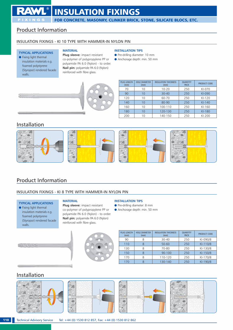
110 Technical Advisory Service Tel: +44 (0) 1530 812 857, Fax: +44 (0) 1530 812 862
INSULATION FIXINGSFOR CONCRETE, MASONRY, CLINKER BRICK, STONE, SILICATE BLOCS, ETC.
INSULATION FIXINGS - KI 10 TYPE WITH HAMMER-IN NYLON PIN
TYPICAL APPLICATIONSe Fixing light thermal
insulation materials e.g. foamed polystyrene (Styropor) rendered facade walls.
MATERIAL Plug sleeve: impact resistant co-polymer of polypropylene PP or polyamide PA 6.0 (Nylon) - to order. Nail pin: polyamide PA 6.0 (Nylon) reinforced with fibre glass.
INSTALLATION TIPSe Pre-drilling diameter: 10 mm e Anchorage depth: min. 50 mm
Product Information
Installation
PLUG LENGTH(mm)
HOLE DIAMETER(mm)
INSULATION THICKNESS(mm)
QUANTITY PACK PRODUCT CODE
70 10 10-20 250 KI-07090 10 30-40 250 KI-090120 10 60-70 250 KI-120140 10 80-90 250 KI-140160 10 100-110 250 KI-160180 10 120-130 250 KI-180200 10 140-150 250 KI-200
INSULATION FIXINGS - KI 8 TYPE WITH HAMMER-IN NYLON PIN
TYPICAL APPLICATIONSe Fixing light thermal
insulation materials e.g. foamed polystyrene (Styropor) rendered facade walls.
MATERIAL Plug sleeve: impact resistant co-polymer of polypropylene PP or polyamide PA 6.0 (Nylon) - to order. Nail pin: polyamide PA 6.0 (Nylon) reinforced with fibre glass.
INSTALLATION TIPSe Pre-drilling diameter: 8 mm e Anchorage depth: min. 50 mm
Product Information
Installation
PLUG LENGTH(mm)
HOLE DIAMETER(mm)
INSULATION THICKNESS(mm)
QUANTITY PACK PRODUCT CODE
90 8 30-40 250 KI-090/8110 8 50-60 250 KI-110/8130 8 70-80 250 KI-130/8150 8 90-100 250 KI-150/8170 8 110-120 250 KI-170/8170 8 130-140 250 KI-190/8
RAWL_KATALOG_2007_2008.indb 110RAWL_KATALOG_2007_2008.indb 110 2007-10-15 14:46:252007-10-15 14:46:25

111Technical Advisory Service e-mail: [email protected] OR [email protected]
FOR CONCRETE, MASONRY, CLINKER BRICK, STONE, SILICATE BLOCS, ETC.
INSULATION FIXINGS
INSULATION SUPPORT – KIK TYPE ONE PIECE WITH NO PIN
Product Information
TYPICAL APPLICATIONSe For fixings light insulation boards, not exposed
to influence of suction wind forces e.g. by insulation of: building substructure, basement walls, window and door reveals, building plinths.
MATERIAL Plug sleeve: impact resistant co-polymer of polypropylene PP
INSTALLATION TIPSe Pre-drilling diameter: 8 mm e Anchorage depth: min. 30 mm
Installation
PLUG DESCRIPTION
HOLE DIAMETER(mm)
INSULATION THICKNESS
(mm)
QUANTITY PACK PRODUCT CODE
35 x 70 8 10-20 400 KIK-07035 x 90 8 30-40 400 KIK-090
METAL FIRE RESISTANT INSULATION SUPPORT - MKI TYPE
Product Information
TYPICAL APPLICATIONSe For fixing mineral wool to
facade walls in all applications where fire-resistance is required.
MATERIAL Electro-zinc coated steel or stainless steel A2 – to order.
INSTALLATION TIPSe Pre-drilling diameter: 8 mm e Anchorage depth: min. 50 mm
InstallationPLUG LENGTH
(mm)HOLE DIAMETER
(mm)QUANTITY
PACK PRODUCT CODE
90 8 250 MKI-090/8110 8 250 MKI-110/8140 8 250 MKI-140/8170 8 250 MKI-170/8200 8 250 MKI-200/8
INSULATION FLANGE WITH COVER CAP – KC TYPE
Product Information
Installation
TYPICAL APPLICATIONSe For fixing both light polystyrene and
heavy mineral wool boards - in combination with appropriate screws - to facade walls made from: timber, sheet metal, plasterboard, etc.
MATERIAL Impact resistant co-polymer of polypropylene PP or polyamide PA 6.0 (Nylon) - to order.
INSTALLATION TIPSe Pre-drilling diameter: 10 mm e Anchorage depth: min. 50 mm
FLANGE DIAMETER
(mm)
QUANTITY PACK PRODUCT CODE
60 200 KC
RAWL_KATALOG_2007_2008.indb 111RAWL_KATALOG_2007_2008.indb 111 2007-10-15 14:46:502007-10-15 14:46:50

112 Technical Advisory Service Tel: +44 (0) 1530 812 857, Fax: +44 (0) 1530 812 862
CORNER BEADS FOR DRYWALL & PLASTERBOARD
Aluminium Corner Beads
LENGTH(cm) QUANTITY PRODUCT CODE
250 50 NAL-25300 50 NAL-30
Aluminium Corner Half-bead
LENGTH(cm) QUANTITY PRODUCT CODE
250 50 NAL-P-25
PVC Corner Bead
LENGTH(cm) QUANTITY PRODUCT CODE
250 200 NAP-25300 200 NAP-30
PVC Corner Arch Bead
LENGTH(cm) QUANTITY PRODUCT CODE
250 25 NALUK-25300 25 NALUK-30
Aluminium Corner Beads With Mesh
LENGTH(cm) MESH TYPE QUANTITY PRODUCT CODE
250 8 x 8 20 NALS-25300 8 x 8 20 NALS-30
PVC Corner Bead With Mesh
LENGTH(cm) MESH TYPE QUANTITY PRODUCT CODE
250 10 x 10 50 NAPS-25250 10 x 15 50 NAPS-25/10x15
Finishing Beads for Plasterboards
LENGTH(cm)
PLASTERBOARD THICKNESS
(mm)QUANTITY PRODUCT CODE
250 12.5 200 NGK125-25300 12.5 200 NGK125-30
RAWL_KATALOG_2007_2008.indb 112RAWL_KATALOG_2007_2008.indb 112 2007-10-15 14:46:552007-10-15 14:46:55
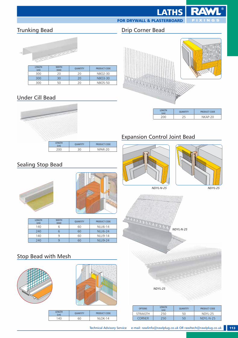
113Technical Advisory Service e-mail: [email protected] OR [email protected]
LATHS FOR DRYWALL & PLASTERBOARD
Trunking Bead
LENGTH(cm)
WIDTH(mm) QUANTITY PRODUCT CODE
300 20 20 NBO2-30300 30 20 NBO3-30300 50 20 NBO5-50
Under Cill Bead
LENGTH(cm) QUANTITY PRODUCT CODE
200 30 NPAR-20
Drip Corner Bead
LENGTH(cm) QUANTITY PRODUCT CODE
200 25 NKAP-20
Sealing Stop Bead
LENGTH(cm)
WIDTH(mm) QUANTITY PRODUCT CODE
140 6 60 NLU6-14240 6 60 NLU6-24140 9 60 NLU9-14240 9 60 NLU9-24
Stop Bead with Mesh
LENGTH(cm) QUANTITY PRODUCT CODE
140 60 NLOK-14
NDYL-25NDYL-N-25
OPTIONS LENGTH(cm) QUANTITY PRODUCT CODE
STRAIGTH 250 50 NDYL-25CORNER 250 50 NDYL-N-25
NDYL-25
NDYL-N-25
Expansion Control Joint Bead
RAWL_KATALOG_2007_2008.indb 113RAWL_KATALOG_2007_2008.indb 113 2007-10-15 14:47:072007-10-15 14:47:07

114 Technical Advisory Service Tel: +44 (0) 1530 812 857, Fax: +44 (0) 1530 812 862
MATERIAL: Sheet steel of thickness 2,0 mm - electro galvanized - 8 �m.
Joist Hangers D-WB
BEAM WIDTH(mm)
BEAM HEIGHT(mm)
PACK WEIGHT(kg)
PACKQUANTITY PRODUCT CODE
40 110 15.2 50 D-WB-411
50 105 15.2 50 D-WB-510
50 165 17.6 40 D-WB-516
60 100 15.2 50 D-WB-610
60 130 15.0 40 D-WB-613
70 125 15.0 40 D-WB-712
80 120 15.0 40 D-WB-812
80 150 11.1 25 D-WB-815
80 180 12.8 25 D-WB-818
90 145 11.1 25 D-WB-914
100 140 11.1 25 D-WB-1014
100 200 11.7 20 D-WB-1020
MATERIAL: Sheet steel of thickness 2,0 mm - electro galvanized - 8 �m.
Two-piece Joist Hanger Plus D-WD
BEAM WIDTH(mm)
BEAM HEIGHT(mm)
PACK WEIGHT(kg) PACK QUANTITY PRODUCT CODE
30 100 7.5 25 D-WD-310
30 120 9.0 25 D-WD-312
30 150 10.4 25 D-WD-315
Joist Hanger With Concealed Flanges D-WC
MATERIAL: Sheet steel of thickness 2,0 mm - electro galvanized - 8 �m.
Rafter Twist Straps D-SP-LP
MATERIAL: Sheet steel of thickness 2,0 mm - electro galvanized - 8 �m.
HANGER DIMENSION(mm)
PACK WEIGHT
(kg)
PACK QUANTITY
PRODUCT CODE
RIGHT LEFT
170 x 30 x 30 9.8 100 D-SP-170P D-SP-170L
210 x 30 x 30 6.6 50 D-SP-210P D-SP-210L
250 x 30 x 30 8.3 50 D-SP-250P D-SP-250L
290 x 30 x 30 4.1 20 D-SP-290P D-SP-290L
330 x 40 x 40 4.7 20 D-SP-330P D-SP-330L
370 x 40 x 40 5.4 20 D-SP-370P D-SP-370L
BEAM WIDTH(mm)
BEAM HEIGHT(mm)
PACK WEIGHT(kg)
PACKQUANTITY PRODUCT CODE
40 110 13.0 50 D-WC-411
50 105 13.0 50 D-WC-510
60 100 13.0 50 D-WC-610
70 125 15.0 40 D-WC-712
80 120 15.0 40 D-WC-812
80 150 11.1 25 D-WC-815
80 180 12.8 25 D-WC-818
90 145 11.1 25 D-WC-914
100 140 11.1 25 D-WC-1014
WOOD CONNECTORS
RAWL_KATALOG_2007_2008.indb 114RAWL_KATALOG_2007_2008.indb 114 2007-10-15 14:47:302007-10-15 14:47:30

115Technical Advisory Service e-mail: [email protected] OR [email protected]
WOOD CONNECTORS
Strap Ties Plus D-LP
Universal Rafter Twist Straps D-SP
MATERIAL: Sheet steel of thickness 2,0 mm - electro galvanized - 8 �m.
HANGER DIMENSION(mm)
PACK WEIGHT(kg)
PACK QUANTITY PRODUCT CODE
170 x 35 x 35 8.3 100 D-SP-170
210 x 35 x 35 6.3 50 D-SP-210
250 x 35 x 35 8.2 50 D-SP-250
Tie Plates
MATERIAL: Sheet steel of thickness 2,0 mm - electro galvanized - 8 �m.
DIMENSION (W x L)(mm)
PACK WEIGHT(kg)
PACK QUANTITY PRODUCT CODE
40 x 100 5,7 100 D-PP-410
40 x 120 6,9 100 D-PP-412
40 x 160 9,2 100 D-PP-416
40 x 200 11,5 100 D-PP-420
40 x 300 8,8 50 D-PP-430
60 x 100 4,4 50 D-PP-610
60 x 120 5,2 50 D-PP-612
60 x 140 6,0 50 D-PP-614
60 x 160 7,0 50 D-PP-616
60 x 200 8,7 50 D-PP-620
60 x 240 10,4 50 D-PP-624
60 x 300 13,0 50 D-PP-630
80 x 160 9,6 50 D-PP-816
80 x 200 6,0 25 D-PP-820
80 x 240 7,0 25 D-PP-824
80 x 260 7,6 25 D-PP-826
80 x 300 8,8 25 D-PP-830
80 x 400 9,7 20 D-PP-840
100 x 100 7,2 50 D-PP-1010
100 x 120 8,6 50 D-PP-1012
100 x 140 5,0 25 D-PP-1014
100 x 160 6,0 25 D-PP-1016
100 x 200 7,2 25 D-PP-1020
100 x 240 8,8 25 D-PP-1024
100 x 260 9,4 25 D-PP-1026
100 x 300 10,8 25 D-PP-1030
100 x 400 11,6 20 D-PP-1040
100 x 500 14,9 20 D-PP-1050
120 x 140 6,1 25 D-PP-1214
120 x 160 7,0 25 D-PP-1216
120 x 200 8,8 25 D-PP-1220
120 x 240 10,4 25 D-PP-1224
120 x 260 11,3 25 D-PP-1226
120 x 300 13,0 25 D-PP-1230
140 x 400 8,3 10 D-PP-1440
DIMENSION (W x L)(mm)
PACK WEIGHT(kg)
PACK QUANTITY PRODUCT CODE
35 x 100 5.5 100 D-LP-310
55 x 140 6.7 50 D-LP-514
40 x 180 6.9 50 D-LP-418
65 x 180 9.6 50 D-LP-618
90 x 195 8.6 25 D-LP-919
MATERIAL: Sheet steel of thickness 2,0 mm - electro galvanized - 8 �m.
RAWL_KATALOG_2007_2008.indb 115RAWL_KATALOG_2007_2008.indb 115 2007-10-15 14:47:432007-10-15 14:47:43

116 Technical Advisory Service Tel: +44 (0) 1530 812 857, Fax: +44 (0) 1530 812 862
WOOD CONNECTORS
Strap Ties Plus D-LWG
MATERIAL: Sheet steel - hot dip galvanized.
DIMENSION (T x L x W)(mm)
PACK WEIGHT(kg)
PACK QUANTITY PRODUCT CODE
2.5 x 170 x 30 5.0 50 D-LWG-170
4.0 x 195 x 35 10.2 50 D-LWG-195
Perforated Angle Brackets Plus D-LA
MATERIAL: Sheet steel - electro galvanized - 8 �m.
ANGLE THICKNESS
(mm)
ANGLE DIMENSION(mm)
PACKWEIGHT
(kg)
PACK QUANTITY PRODUCT CODE
2,0
40 x 200 3,4 25 D-LA-422
40 x 300 4,9 25 D-LA-432
40 x 400 6,4 25 D-LA-442
3,040 x 200 4,6 25 D-LA-423
40 x 300 6,1 25 D-LA-433
Perforated Angle Brackets EXTREME
MATERIAL: Sheet steel of thickness 4.0 mm - electro galvanized - 8 �m.
ANGLE DIMENSION(mm)
PACKWEIGHT
(kg)
PACK QUANTITY PRODUCT CODE
40 x 300 9,8 25 D-LX-434
40 x 400 12,7 25 D-LX-444
Strap Ties D-LW
MATERIAL: Sheet steel of thickness 4.0 mm - electro galvanized - 8 �m.
STRAP TIES THICKNESS
(mm)
STRAP TIES DIMENSION
(mm)
PACK QUANTITY PRODUCT CODE
2,0
40 x 15 100 D-LW-40
50 x 15 100 D-LW-50
75 x 15 100 D-LW-75
100 x 15 50 D-LW-100
4,0
150 x 20 50 D-LW-150
190 x 20 50 D-LW-190
240 x 20 50 D-LW-240
RAWL_KATALOG_2007_2008.indb 116RAWL_KATALOG_2007_2008.indb 116 2007-10-15 14:47:532007-10-15 14:47:53
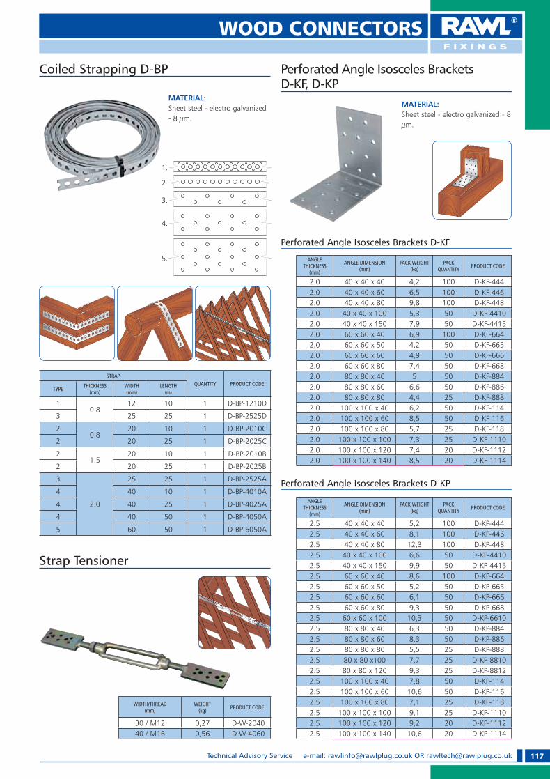
117Technical Advisory Service e-mail: [email protected] OR [email protected]
WOOD CONNECTORS
Coiled Strapping D-BP
STRAPQUANTITY PRODUCT CODE
TYPE THICKNESS(mm)
WIDTH(mm)
LENGTH(m)
10.8
12 10 1 D-BP-1210D
3 25 25 1 D-BP-2525D
20.8
20 10 1 D-BP-2010C
2 20 25 1 D-BP-2025C
21.5
20 10 1 D-BP-2010B
2 20 25 1 D-BP-2025B
3
2.0
25 25 1 D-BP-2525A
4 40 10 1 D-BP-4010A
4 40 25 1 D-BP-4025A
4 40 50 1 D-BP-4050A
5 60 50 1 D-BP-6050A
Perforated Angle Isosceles Brackets D-KF, D-KP
MATERIAL: Sheet steel - electro galvanized - 8 �m.
ANGLE THICKNESS
(mm)
ANGLE DIMENSION(mm)
PACK WEIGHT(kg)
PACK QUANTITY PRODUCT CODE
2.0 40 x 40 x 40 4,2 100 D-KF-4442.0 40 x 40 x 60 6,5 100 D-KF-4462.0 40 x 40 x 80 9,8 100 D-KF-4482.0 40 x 40 x 100 5,3 50 D-KF-44102.0 40 x 40 x 150 7,9 50 D-KF-44152.0 60 x 60 x 40 6,9 100 D-KF-6642.0 60 x 60 x 50 4,2 50 D-KF-6652.0 60 x 60 x 60 4,9 50 D-KF-6662.0 60 x 60 x 80 7,4 50 D-KF-6682.0 80 x 80 x 40 5 50 D-KF-8842.0 80 x 80 x 60 6,6 50 D-KF-8862.0 80 x 80 x 80 4,4 25 D-KF-8882.0 100 x 100 x 40 6,2 50 D-KF-1142.0 100 x 100 x 60 8,5 50 D-KF-1162.0 100 x 100 x 80 5,7 25 D-KF-1182.0 100 x 100 x 100 7,3 25 D-KF-11102.0 100 x 100 x 120 7,4 20 D-KF-11122.0 100 x 100 x 140 8,5 20 D-KF-1114
Perforated Angle Isosceles Brackets D-KF
ANGLE THICKNESS
(mm)
ANGLE DIMENSION(mm)
PACK WEIGHT(kg)
PACK QUANTITY PRODUCT CODE
2.5 40 x 40 x 40 5,2 100 D-KP-4442.5 40 x 40 x 60 8,1 100 D-KP-4462.5 40 x 40 x 80 12,3 100 D-KP-4482.5 40 x 40 x 100 6,6 50 D-KP-44102.5 40 x 40 x 150 9,9 50 D-KP-44152.5 60 x 60 x 40 8,6 100 D-KP-6642.5 60 x 60 x 50 5,2 50 D-KP-6652.5 60 x 60 x 60 6,1 50 D-KP-6662.5 60 x 60 x 80 9,3 50 D-KP-6682.5 60 x 60 x 100 10,3 50 D-KP-66102.5 80 x 80 x 40 6,3 50 D-KP-8842.5 80 x 80 x 60 8,3 50 D-KP-8862.5 80 x 80 x 80 5,5 25 D-KP-8882.5 80 x 80 x100 7,7 25 D-KP-88102.5 80 x 80 x 120 9,3 25 D-KP-88122.5 100 x 100 x 40 7,8 50 D-KP-1142.5 100 x 100 x 60 10,6 50 D-KP-1162.5 100 x 100 x 80 7,1 25 D-KP-1182.5 100 x 100 x 100 9,1 25 D-KP-11102.5 100 x 100 x 120 9,2 20 D-KP-11122.5 100 x 100 x 140 10,6 20 D-KP-1114
Perforated Angle Isosceles Brackets D-KP
MATERIAL: Sheet steel - electro galvanized - 8 �m.
Strap Tensioner
WIDTH/THREAD(mm)
WEIGHT(kg) PRODUCT CODE
30 / M12 0,27 D-W-204040 / M16 0,56 D-W-4060
1.
2.
3.
4.
5.
RAWL_KATALOG_2007_2008.indb 117RAWL_KATALOG_2007_2008.indb 117 2007-10-15 14:48:022007-10-15 14:48:02

118 Technical Advisory Service Tel: +44 (0) 1530 812 857, Fax: +44 (0) 1530 812 862
Angle Brackets Plus D-ZN
MATERIAL: Sheet steel of thickness 2.5 mm - electro galvanized - 8 �m.
BRACKET DIMENSION(mm)
PACK WEIGHT(kg)
PACK QUANTITY PRODUCT CODE
40 x 160 x 40 8,5 50 D-ZN-4164
40 x 120 x 40 12,2 100 D-ZN-4124
40 x 90 x 40 9,2 100 D-ZN-4904
50 x 90 x 50 10,2 100 D-ZN-5905
60 x 35 x 60 9,0 100 D-ZN-6356
60 x 90 x 60 6,2 50 D-ZN-6906
80 x 60 x 40 6,4 50 D-ZN-8604
90 x 120 x 40 8,6 50 D-ZN-9124
Angle Brackets Plus D-ZK
MATERIAL: Sheet steel - electro galvanized - 8 �m.
BRACKET THICKNESS
(mm
BRACKET DIMENSION(mm)
PACK WEIGHT(kg)
PACK QUANTITY PRODUCT CODE
2,5
50 x 50 x 35 8,2 150 D-ZK-553
70 x 70 x 55 6,9 50 D-ZK-70
90 x 90 x 65 9,7 50 D-ZK-90
3,0
60 x 60 x 45 5,0 50 D-ZK-60
90 x 90 x 40 8,0 50 D-ZK-994
105 x 105 x 90 9,3 25 D-ZK-105
Reinforced with Gusset
BRACKET THICKNESS
(mm
BRACKET DIMENSION(mm)
PACK WEIGHT(kg)
PACK QUANTITY PRODUCT CODE
2,5
70 x 70 x 55 6,9 50 D-ZK-70WZ/2
90 x 90 x 65 9,7 50 D-ZK-90WZ/2
105 x 105 x 90 9,3 25 D-ZK-105WZ/2
3,0
70 x 70 x 55 6,9 50 D-ZK-70WZ
90 x 90 x 65 9,7 50 D-ZK-90WZ
105 x 105 x 90 9,3 25 D-ZK-105WZAngle Brackets 135o Plus D-ZS
MATERIAL: Sheet steel of thickness 4.0 mm - electro galvanized - 8 �m.
BRACKET DIMENSION(mm)
PACK WEIGHT(kg)
PACK QUANTITY PRODUCT CODE
50 x 50 x 35 3,4 50 D-ZS-553
90 x 90 x 40 8,0 50 D-ZS-994
70 x 70 x 55 6,9 50 D-ZS-775
90 x 90 x 65 9,7 50 D-ZS-996
105 x 105 x 90 7,9 25 D-ZS-119
Adjustable Angle Bracket D-ZKR
MATERIAL: Sheet steel of thickness 2.0 mm - electro galvanized - 8 �m.
BRACET DIMENSION(mm)
PACK WEIGHT(kg)
PACK QUANTITY PRODUCT CODE
60 x 30 x 60 3,1 50 D-ZKR-636
60 x 40 x 60 5,0 50 D-ZKR-646
80 x 50 x 30 4,6 100 D-ZKR-853
80 x 65 x 20 3,9 50 D-ZKR-862
WOOD CONNECTORS
RAWL_KATALOG_2007_2008.indb 118RAWL_KATALOG_2007_2008.indb 118 2007-10-15 14:48:112007-10-15 14:48:11

119Technical Advisory Service e-mail: [email protected] OR [email protected]
WOOD CONNECTORS
MATERIAL: Sheet steel of thickness 2.0 mm - electro galvanized - 8 �m.
BRACKET DIMENSION(mm)
PACK WEIGHT(kg)
PACK QUANTITY PRODUCT CODE
25 x 25 x 15 0,8 100 D-MI-2215
30 x 30 x 15 1,0 100 D-MI-3315
40 x 40 x 15 1,2 100 D-MI-4415
50 x 50 x 15 1,5 100 D-MI-5515
60 x 60 x 20 2,4 100 D-MI-6620
80 x 80 x 20 3,2 100 D-MI-8820
100 x 100 x 20 4,0 100 D-MI-1120
Angle Beam BracketsType Light D-MI
MATERIAL: Sheet steel of thickness 5.0 mm - hot dip galvanized.
BRACKET DIMENSION(mm)
PACK WEIGHT(kg)
PACK QUANTITY PRODUCT CODE
80 x 80 x 20 1,6 20 D-MK-085
100 x 100 x 20 2,0 20 D-MK-105
120 x 120 x 20 2,4 20 D-MK-125
140 x 140 x 20 2,8 20 D-MK-145
160 x 160 x 20 3,2 20 D-MK-165
180 x 180 x 20 3,6 20 D-MK-185
Angle Beam Brackets Type Heavy D-MK
Angle Beam Brackets D-KB
MATERIAL: Sheet steel - electro galvanized - 8 �m.
BRACKET THICKNESS
(mm
BRACKET DIMENSION(mm)
PACK WEIGHT(kg)
PACK QUANTITY PRODUCT CODE
2.5 100 x 75 x 30 5,0 50 D-KB-1075
4.0100 x 50 x 50 8,8 40 D-KB-105
120 x 80 x 35 4,1 20 D-KB-1280
5,0 180 x 120 x 40 11,2 25 D-KB-1812
MATERIAL: Sheet steel of thickness 2.0 mm - electro galvanized - 8 �m.
Angle Beam Brackets Type D-MS
BRACKET DIMENSION(mm)
PACK WEIGHT(kg)
PACK QUANTITY PRODUCT CODE
30 x 30 x 30 x 2 2,7 100 D-MS-333
40 x 40 x 40 x 2 4,9 100 D-MS-444
60 x 60 x 60 x 2 5,6 50 D-MS-666
WOOD CONNECTORS
RAWL_KATALOG_2007_2008.indb 119RAWL_KATALOG_2007_2008.indb 119 2007-10-15 14:48:202007-10-15 14:48:20

120 Technical Advisory Service Tel: +44 (0) 1530 812 857, Fax: +44 (0) 1530 812 862
Universal Angle Brackets D-ZU
BRACKET DIMENSION(mm)
PACK WEIGHT(kg)
PACK QUANTITY PRODUCT CODE
30 x 30 x 25 3,1 200 D-ZU-3325
40 x 40 x 25 3,6 200 D-ZU-4425
50 x 50 x 25 4,9 200 D-ZU-5525
60 x 60 x 25 4,0 100 D-ZU-6625
50 x 50 x 30 3,9 100 D-ZU-5530
50 x 70 x 30 4,4 100 D-ZU-5730
“L” Shaped Strap Ties D-KN
MATERIAL: Sheet steel - electro galvanized - 8 �m.
THICKNESS(mm
BRACKET DIMENSION(mm)
PACK WEIGHT(kg)
PACK QUANTITY PRODUCT CODE
2.0
50 x 50 x 10 1,3 100 D-KN-50
60 x 60 x 10 1,6 100 D-KN-60
75 x 75 x 12 2,5 100 D-KN-75
100 x 100 x 15 4,2 100 D-KN-100
2.5 150 x 150 x 25 7,0 50 D-KN-150
3.0200 x 200 x 31 13,1 50 D-KN-200
250 x 250 x 31 8,35 25 D-KN-250
4.0 300 x 300 x 41 17,9 25 D-KN-300
MATERIAL: Sheet steel of thickness 2.0 mm - electro galvanized - 8 �m.
Angle Connector
MATERIAL: Sheet steel of thickness 2.0 mm - hot dip galvanized.
DIMENSION(mm)
PACK WEIGHT(kg)
PACK QUANTITY PRODUCT CODE
120X40X40X2 5,8 50 D-KG 1244
“T” Shaped Strap Ties
MATERIAL: Sheet steel of thickness 2.0 mm - electro galvanized - 8 �m.
STRAP TIES DIMENSION(mm)
PACK WEIGHT(kg)
PACK QUANTITY PRODUCT CODE
70 x 50 x 16 1,2 50 D-T-7050
WOOD CONNECTORS
RAWL_KATALOG_2007_2008.indb 120RAWL_KATALOG_2007_2008.indb 120 2007-10-15 14:48:292007-10-15 14:48:29

121Technical Advisory Service e-mail: [email protected] OR [email protected]
WOOD CONNECTORS
Joist Connector
MATERIAL: Sheet steel - hot dip galvanized.
LENGTH(mm)
PACK QUANTITY PRODUCT CODE
250 10 D-KL-250
Buffer Roo� ng Strut
MATERIAL: Sheet steel - electro galvanized - 8 �m
DIMENSION(mm)
PACK QUANTITY PRODUCT CODE
50 x 55 x 1.5 / 7,0 x 210 10 D-PD-210
50 x 55 x 1.5 / 7,5 x 260 10 D-PD-260
50 x 55 x 1.5 / 8,0 x 310 10 D-PD-310
Toothed Plate Connectors
MATERIAL: Sheet steel - electro galvanized - 8 �m
One-sided
OUTERDIAMETER
(mm)
INNERDIAMETER
(mm)
SHEETTHICKNESS
(mm)
PACK WEIGHT
(kg)
PACK QUANTITY PRODUCT CODE
48 17 1.0 2.1 200 D-DD-48
62 21 1.2 3.3 200 D-DD-62
75 26 1.25 4.9 100 D-DD-75
Double-sided
OUTERDIAMETER
(mm)
INNERDIAMETER
(mm)
SHEETTHICKNESS
(mm)
PACK WEIGHT
(kg)
PACK QUANTITY PRODUCT CODE
48 17 1.0 2.1 300 D-ED-48
62 21 1.2 3.3 100 D-ED-62
75 26 1.25 4.9 100 D-ED-75
Ring Shank Timber Nails
DIAMETER(mm)
LENGTH(mm)
PRODUCT CODE
1 KG PACK 1 KG PACK
4.0 35 D-I-435 D-I-435-5
4.0 40 D-I-440 D-I-440-5
4.0 50 D-I-450 D-I-450-5
4.0 60 D-I-460 D-I-460-5
4.0 75 D-I-475 D-I-475-5
4.0 100 D-I-4100 D-I-4100-5
4.0 125 D-I-4125 D-I-4125-5
MATERIAL: Sheet steel - electro galvanized - 12 �m
WOOD CONNECTORS
RAWL_KATALOG_2007_2008.indb 121RAWL_KATALOG_2007_2008.indb 121 2007-10-15 14:48:452007-10-15 14:48:45
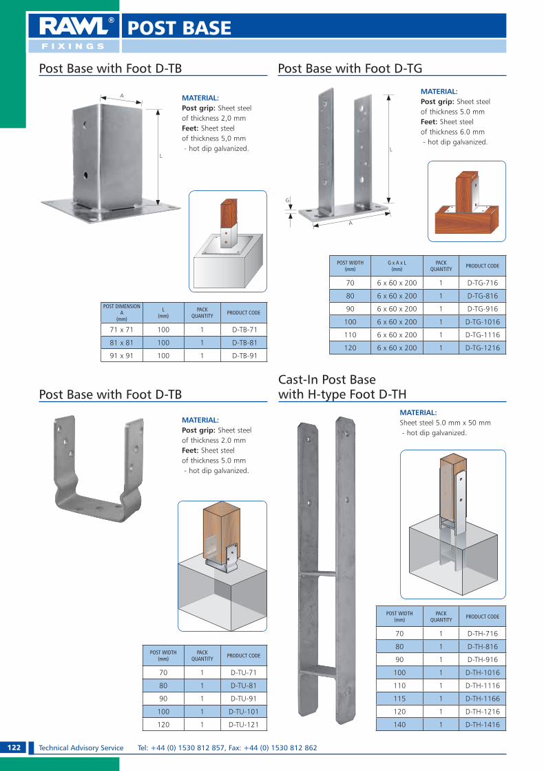
122 Technical Advisory Service Tel: +44 (0) 1530 812 857, Fax: +44 (0) 1530 812 862
POST BASE
Post Base with Foot D-TB
MATERIAL: Post grip: Sheet steel of thickness 2,0 mm Feet: Sheet steel of thickness 5,0 mm - hot dip galvanized.
POST DIMENSIONA
(mm)
L(mm)
PACK QUANTITY PRODUCT CODE
71 x 71 100 1 D-TB-71
81 x 81 100 1 D-TB-81
91 x 91 100 1 D-TB-91
LL
G
A
A
Post Base with Foot D-TG
MATERIAL: Post grip: Sheet steel of thickness 5.0 mm Feet: Sheet steel of thickness 6.0 mm - hot dip galvanized.
POST WIDTH(mm)
G x A x L(mm)
PACK QUANTITY PRODUCT CODE
70 6 x 60 x 200 1 D-TG-716
80 6 x 60 x 200 1 D-TG-816
90 6 x 60 x 200 1 D-TG-916
100 6 x 60 x 200 1 D-TG-1016
110 6 x 60 x 200 1 D-TG-1116
120 6 x 60 x 200 1 D-TG-1216
Cast-In Post Base with H-type Foot D-TH
MATERIAL: Sheet steel 5.0 mm x 50 mm - hot dip galvanized.
POST WIDTH(mm)
PACK QUANTITY PRODUCT CODE
70 1 D-TH-716
80 1 D-TH-816
90 1 D-TH-916
100 1 D-TH-1016
110 1 D-TH-1116
115 1 D-TH-1166
120 1 D-TH-1216
140 1 D-TH-1416
Post Base with Foot D-TB
MATERIAL: Post grip: Sheet steel of thickness 2.0 mm Feet: Sheet steel of thickness 5.0 mm - hot dip galvanized.
POST WIDTH(mm)
PACK QUANTITY PRODUCT CODE
70 1 D-TU-71
80 1 D-TU-81
90 1 D-TU-91
100 1 D-TU-101
120 1 D-TU-121
RAWL_KATALOG_2007_2008.indb 122RAWL_KATALOG_2007_2008.indb 122 2007-10-15 14:48:502007-10-15 14:48:50

123Technical Advisory Service e-mail: [email protected] OR [email protected]
POST BASE
Post Base with Reinforcement Bars D-TL
POST WIDTH(mm)
L(mm)
PACK QUANTITY PRODUCT CODE
80 200 1 D-TL-808
Post Base with Reinforcement Bars D-TC
POST WIDTH(mm)
PACK QUANTITY PRODUCT CODE
70 1 D-TE-715
90 1 D-TE-915
100 1 D-TE-1015
120 1 D-TE-1215
MATERIAL: Post grip: Sheet steel 5.0 mm x 50 mmT-bar: 40 x 40 x 200 mm - hot dip galvanized.
POST WIDTH(mm)
L(mm)
PACK QUANTITY PRODUCT CODE
100 200 1 D-TA-200
MATERIAL: Post grip: Sheet steel 5.0 mm x 50 mmFeet: Embedment rod - hot dip galvanized.
L
POST WIDTH(mm)
L(mm)
PACK QUANTITY PRODUCT CODE
70
200
1 D-TC-716
80 1 D-TC-816
90 1 D-TC-916
100 1 D-TC-1016
110 1 D-TC-1116
120 1 D-TC-1216
140 1 D-TC-1416
MATERIAL: Post grip: Sheet steel 5.0 mm x 50 mmFeet: Embedment rod - hot dip galvanized.
L
MATERIAL: Post grip: Sheet steel of thickness 5.0 mm.Feet: Embedment rod - hot dip galvanized.
L
Post Base with Reinforcement Bars D-TA
Cast-In Post Base with T-bar D-TE
RAWL_KATALOG_2007_2008.indb 123RAWL_KATALOG_2007_2008.indb 123 2007-10-15 14:49:062007-10-15 14:49:06

124 Technical Advisory Service Tel: +44 (0) 1530 812 857, Fax: +44 (0) 1530 812 862
POST BASE/ACCESORIES
Post Base For Hammering
MATERIAL: Sheet steel thickness 1.5 mm - hot dip galvanized.
A(mm)
L(mm)
WEIGHT OF 1 PCS(kg)
PACK QUANTITY PRODUCT CODE
50 x 50 750 13.0 1 D-TD-5175
70 x 70 750 13.2 1 D-TD-7175
70 x 70 900 13.5 1 D-TD-7190
90 x 90 750 13.3 1 D-TD-9175
90 x 90 900 13.8 1 D-TD-9190
100 x 100 750 14.3 1 D-TD-1075
100 x 100 900 14.3 1 D-TD-1090
120 x 120 900 14.3 1 D-TD-1290
Square Socket
A(mm)
L(mm)
WEIGHT OF 1 PCS(kg)
PACK QUANTITY PRODUCT CODE
80 750 13.5 1 D-TDO-8175
80 900 13.5 1 D-TDO-8190
100 750 14.3 1 D-TDO-1075
100 900 14.3 1 D-TDO-1090
Round Socket
Gate Post Finials
POST DIMENSION(mm)
PACK QUANTITY
PRODUCT CODE
SQUARE ROUND
71 x 71 10 D-TK-71 D-TK-71O
91 x 91 10 D-TK-91 D-TK-91O
MATERIAL: Cooper sheet thickness 1.5 mm.
POST DIMENSION(mm)
PACK QUANTITY
PRODUCT CODE
SQUARE ROUND
71 x 71 10 D-TKM-71 D-TKM-71O
91 x 91 10 D-TKM-91 D-TKM-91O
Pergola Bracket D-OP
MATERIAL: Sheet steel thickness 2.0 mm - electro galvanized - 8 �m
BRACKET DIMENSION(mm)
PACK WEIGHT(kg)
PACK QUANTITY PRODUCT CODE
31 x 30 x 37 1.8 50 D-OP- 333
RAWL_KATALOG_2007_2008.indb 124RAWL_KATALOG_2007_2008.indb 124 2007-10-15 14:49:212007-10-15 14:49:21

125Technical Advisory Service e-mail: [email protected] OR [email protected]
SHELF BRACKETS
Shelf Brackets
Shelf Brackets – Reinforced
Painted in White
BRACKETDIMENSION
(mm)
PACK QUANTITY PRODUCT CODE
100 x 75 24 D-WT-1075
125 x 100 24 D-WT-1210
150 x 125 24 D-WT-1512
200 x 150 24 D-WT-2015
250 x 200 24 D-WT-2520
300 x 250 24 D-WT-3025
350 x 300 24 D-WT-3530
400 x 350 24 D-WT-4035
Painted in Silver
BRACKET DIMENSION
(mm)
PACK QUANTITY PRODUCT CODE
100 x 75 24 D-WT-1075S
125 x 100 24 D-WT-1210S
150 x 125 24 D-WT-1512S
200 x 150 24 D-WT-2015S
250 x 200 24 D-WT-2520S
300 x 250 24 D-WT-3025S
350 x 300 24 D-WT-3530S
400 x 350 24 D-WT-4035S
BRACKETDIMENSION
(mm)
PACK QUANTITY PRODUCT CODE
30 x 30 100 D-WW-0303B
50 x 50 100 D-WW-0505B
70 x 70 50 D-WW-0707B
100 x 100 50 D-WW-1010B
125 x 125 25 D-WW-1212B
150 x 125 25 D-WW-1512B
200 x 150 20 D-WW-2015B
Painted in Black
BRACKETDIMENSION
(mm)
PACK QUANTITY PRODUCT CODE
30 x 30 100 D-WW-0303W
50 x 50 100 D-WW-0505W
70 x 70 50 D-WW-0707W
100 x 100 50 D-WW-1010W
125 x 125 25 D-WW-1212W
150 x 125 25 D-WW-1512W
200 x 150 20 D-WW-2015W
Painted in White
Painted in Grey
BRACKET DIMENSION
(mm)
PACK QUANTITY PRODUCT CODE
100 x 75 24 D-WT-1075SR
125 x 100 24 D-WT-1210SR
150 x 125 24 D-WT-1512SR
200 x 150 24 D-WT-2015SR
250 x 200 24 D-WT-2520SR
300 x 250 24 D-WT-3025SR
350 x 300 24 D-WT-3530SR
400 x 350 24 D-WT-4035SR
Painted in Brown
BRACKET DIMENSION
(mm)
PACK QUANTITY PRODUCT CODE
100 x 75 24 D-WT-1075BR
125 x 100 24 D-WT-1210BR
150 x 125 24 D-WT-1512BR
200 x 150 24 D-WT-2015BR
250 x 200 24 D-WT-2520BR
300 x 250 24 D-WT-3025BR
350 x 300 24 D-WT-3530BR
400 x 350 24 D-WT-4035BR
BRACKETDIMENSION
(mm)
PACK QUANTITY PRODUCT CODE
30 x 30 100 D-WW-0303
50 x 50 100 D-WW-0505
70 x 70 50 D-WW-0707
100 x 100 50 D-WW-1010
125 x 125 25 D-WW-1212
150 x 125 25 D-WW-1512
200 x 150 20 D-WW-2015
Painted in Silver
RAWL_KATALOG_2007_2008.indb 125RAWL_KATALOG_2007_2008.indb 125 2007-10-15 14:49:422007-10-15 14:49:42

126 Technical Advisory Service Tel: +44 (0) 1530 812 857, Fax: +44 (0) 1530 812 862
SHELF BRACKETS
Decorative Brackets
Painted in White
BRACKET DIMENSION(mm)
QUANTITYPRODUCT CODE
PACK OUTER
115 x 115 x 13 x 3 12 144 D-WDB-115W
150 x 150 x 13 x 3 12 96 D-WDB-150W
200 x 200 x 13 x 3 12 72 D-WDB-200W
250 x 250 x 13 x 3 12 72 D-WDB-250W
Painted in Black Epoxy
BRACKET DIMENSION(mm)
QUANTITYPRODUCT CODE
PACK OUTER
115 x 115 x 13 x 3 12 144 D-WDB-115B
150 x 150 x 13 x 3 12 96 D-WDB-150B
200 x 200 x 13 x 3 12 72 D-WDB-200B
250 x 250 x 13 x 3 12 72 D-WDB-250B
Painted in Patina Brass
BRACKET DIMENSION(mm)
QUANTITYPRODUCT CODE
PACK OUTER
145 x 110 x 25 x 3 12 144 D-WDB-1410
190 x 140 x 25 x 3 12 96 D-WDB-1914
240 x 190 x 30 x 4 12 72 D-WDB-2419
290 x 240 x 30 x 4 12 72 D-WDB-2924
Folding brackets
BRACKET DIMENSION(mm)
QUANTITYPRODUCT CODE
PACK OUTER
150 x 150 x 22 x 1.5 24 144 D-WFB-150W
200 x 200 x 22 x 1.5 24 144 D-WFB-200W
250 x 250 x 26 x 1.5 24 96 D-WFB-250W
Isoscales - Painted in White
BRACKET DIMENSION(mm)
QUANTITYPRODUCT CODE
PACK OUTER
300 x 160 x 20 x 2 10 50 D-WFB-300W
400 x 220 x 20 x 2 10 50 D-WFB-4 00W
Non-isoscales - Painted in White
RAWL_KATALOG_2007_2008.indb 126RAWL_KATALOG_2007_2008.indb 126 2007-10-15 14:49:562007-10-15 14:49:56

127Technical Advisory Service e-mail: [email protected] OR [email protected]
SHELF BRACKETS
Light Duty Brackets
BRACKET DIMENSION(mm)
QUANTITYPRODUCT CODE
PACK OUTER
150 x 125 x 1.2 10 200 D-WLB-1512W
200 x 150 x 1.2 10 120 D-WLB-2015W
250 x 200 x 1.5 10 70 D-WLB-2520W
300 x 250 x 1.5 10 50 D-WLB-3025W
Painted in White Painted in Brown
BRACKET DIMENSION(mm)
QUANTITYPRODUCT CODE
PACK OUTER
150 x 125 x 1.2 10 200 D-WLB-1512B
200 x 150 x 1.2 10 120 D-WLB-2015B
250 x 200 x 1.5 10 70 D-WLB-2520B
300 x 250 x 1.5 10 50 D-WLB-3025B
Painted in Black
Heavy Duty Brackets
Painted in White
BRACKET DIMENSION(mm)
QUANTITYPRODUCT CODE
PACK OUTER
300 x 200 x 30 x 4 6 36 D-WHB-300W
400 x 250 x 30 x 4 6 24 D-WHB-400W
500 x 330 x 30 x 5 6 18 D-WHB-500W
Painted in Silver
BRACKET DIMENSION(mm)
QUANTITYPRODUCT CODE
PACK OUTER
300 x 200 x 30 x 4 6 36 D-WHB-300SR
400 x 250 x 30 x 4 6 24 D-WHB-400SR
500 x 330 x 30 x 5 6 18 D-WHB-500SR
BRACKET DIMENSION(mm)
QUANTITYPRODUCT CODE
PACK OUTER
150 x 125 x 1.2 10 200 D-WLB-1512BR
200 x 150 x 1.2 10 120 D-WLB-2015BR
250 x 200 x 1.5 10 70 D-WLB-2520BR
300 x 250 x 1.5 10 50 D-WLB-3025BR
RAWL_KATALOG_2007_2008.indb 127RAWL_KATALOG_2007_2008.indb 127 2007-10-15 14:50:052007-10-15 14:50:05
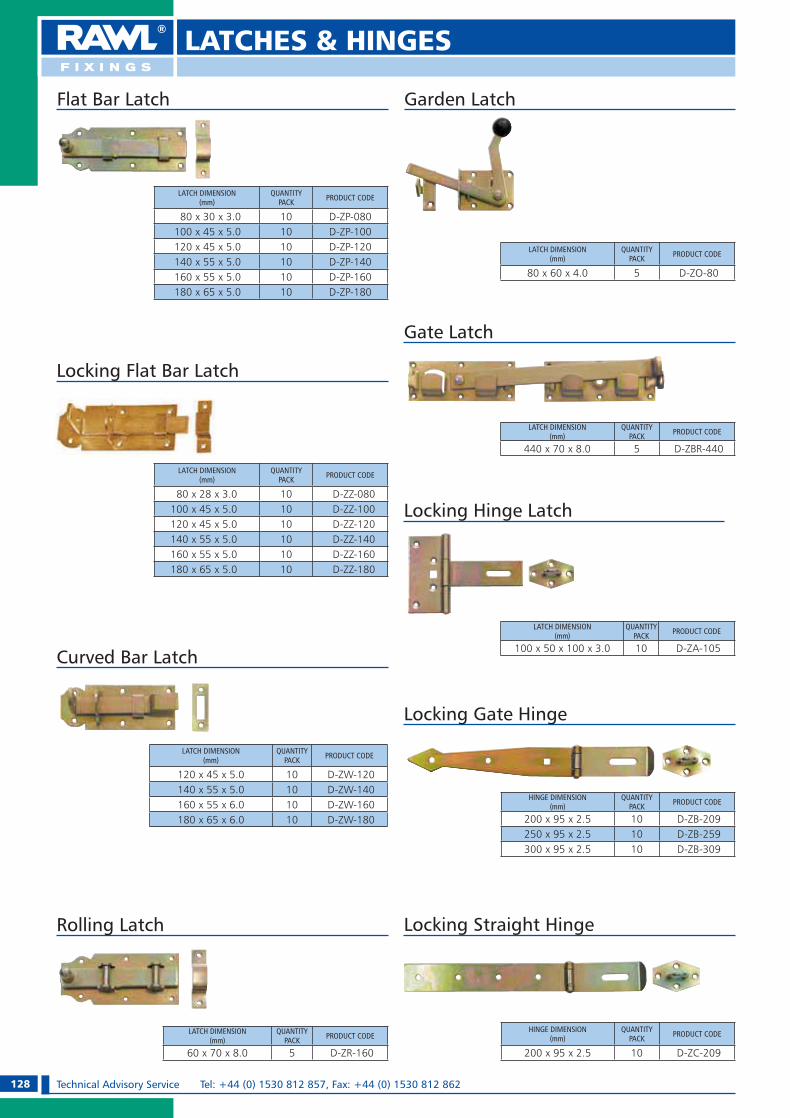
128 Technical Advisory Service Tel: +44 (0) 1530 812 857, Fax: +44 (0) 1530 812 862
LATCHES & HINGES
LATCH DIMENSION(mm)
QUANTITYPACK PRODUCT CODE
80 x 30 x 3.0 10 D-ZP-080100 x 45 x 5.0 10 D-ZP-100120 x 45 x 5.0 10 D-ZP-120140 x 55 x 5.0 10 D-ZP-140160 x 55 x 5.0 10 D-ZP-160180 x 65 x 5.0 10 D-ZP-180
HINGE DIMENSION(mm)
QUANTITYPACK PRODUCT CODE
200 x 95 x 2.5 10 D-ZB-209250 x 95 x 2.5 10 D-ZB-259300 x 95 x 2.5 10 D-ZB-309
HINGE DIMENSION(mm)
QUANTITYPACK PRODUCT CODE
200 x 95 x 2.5 10 D-ZC-209
Locking Hinge Latch
LATCH DIMENSION(mm)
QUANTITYPACK PRODUCT CODE
100 x 50 x 100 x 3.0 10 D-ZA-105
Rolling Latch
LATCH DIMENSION(mm)
QUANTITYPACK PRODUCT CODE
60 x 70 x 8.0 5 D-ZR-160
LATCH DIMENSION(mm)
QUANTITYPACK PRODUCT CODE
120 x 45 x 5.0 10 D-ZW-120140 x 55 x 5.0 10 D-ZW-140160 x 55 x 6.0 10 D-ZW-160180 x 65 x 6.0 10 D-ZW-180
LATCH DIMENSION(mm)
QUANTITYPACK PRODUCT CODE
440 x 70 x 8.0 5 D-ZBR-440
Locking Flat Bar Latch
LATCH DIMENSION(mm)
QUANTITYPACK PRODUCT CODE
80 x 28 x 3.0 10 D-ZZ-080100 x 45 x 5.0 10 D-ZZ-100120 x 45 x 5.0 10 D-ZZ-120140 x 55 x 5.0 10 D-ZZ-140160 x 55 x 5.0 10 D-ZZ-160180 x 65 x 5.0 10 D-ZZ-180
Gate Latch
Curved Bar Latch
Locking Straight Hinge
Locking Gate Hinge
Flat Bar Latch
LATCH DIMENSION(mm)
QUANTITYPACK PRODUCT CODE
80 x 60 x 4.0 5 D-ZO-80
Garden Latch
RAWL_KATALOG_2007_2008.indb 128RAWL_KATALOG_2007_2008.indb 128 2007-10-15 14:50:162007-10-15 14:50:16

129Technical Advisory Service e-mail: [email protected] OR [email protected]
LATCHES & HINGES
Construction Hinge
LATCH DIMENSION(mm)
QUANTITYPACK PRODUCT CODE
100 x 65 x 2.0 10 D-ZE-100125 x 80 x 2.0 10 D-ZE-125150 x 80 x 2.0 10 D-ZE-150
Triangular Hinge
LATCH DIMENSION(mm)
QUANTITYPACK PRODUCT CODE
50 x 25 x 2.5 30 D-ZD-5025100 x 25 x 2.5 30 D-ZD-1025100 x 35 x 2.5 30 D-ZD-1035100 x 50 x 2.5 30 D-ZD-1050150 x 50 x 2.5 30 D-ZD-1550200 x 50 x 2.5 30 D-ZD-2050250 x 50 x 2.5 30 D-ZD-2550300 x 55 x 2.5 10 D-ZD-300350 x 55 x 2.5 10 D-ZD-350400 x 55 x 2.5 10 D-ZD-400500 x 55 x 2.5 10 D-ZD-500
LATCH DIMENSION(mm)
QUANTITYPACK PRODUCT CODE
300 x 30 x 3.0 / Ø 10 10 D-ZI-310400 x 30 x 3.0 / Ø 10 10 D-ZI-410300 x 40 x 5.0 / Ø 13 10 D-ZI-313400 x 40 x 5.0 / Ø 13 10 D-ZI-413500 x 40 x 5.0 / Ø 13 10 D-ZI-513600 x 40 x 5.0 / Ø 13 10 D-ZI-613500 x 45 x 6.0 / Ø 16 10 D-ZI-516600 x 45 x 6.0 / Ø 16 10 D-ZI-616800 x 45 x 6.0 / Ø 16 10 D-ZI-816
LATCH DIMENSION(mm)
QUANTITYPACK PRODUCT CODE
200 x 80 x 50 x 2.5 10 D-ZH-203250 x 80 x 50 x 2.5 10 D-ZH-253300 x 80 x 50 x 2.5 10 D-ZH-303
400 x 100 x 65 x 2.5 10 D-ZH-403300 x 130 x 65 x 4.0 10 D-ZH-304400 x 130 x 65 x 4.0 10 D-ZH-404500 x 130 x 75 x 4.0 10 D-ZH-504600 x 130 x 75 x 4.0 10 D-ZH-604
Gate Hinge
Belt Hinge
French Hinge
LATCH DIMENSION(mm)
QUANTITYPACK PRODUCT CODE
200 x 33 x 2.5 10 D-ZF-200250 x 38 x 2.5 10 D-ZF-250300 x 38 x 2.5 10 D-ZF-300
LATCH DIMENSION(mm)
QUANTITYPACK PRODUCT CODE
200 x 50 x 90 x 35 x 3.0 10 D-ZG-203250 x 45 x 90 x 35 x 3.0 10 D-ZG-253300 x 45 x 90 x 35 x 3.0 10 D-ZG-303350 x 45 x 90 x 35 x 3.0 10 D-ZG-353400 x 45 x 90 x 35 x 3.0 10 D-ZG-403
300 x 65 x 110 x 40 x 4.0 10 D-ZG-304400 x 65 x 110 x 40 x 4.0 10 D-ZG-404500 x 65 x 110 x 40 x 4.0 10 D-ZG-504600 x 65 x 110 x 40 x 4.0 10 D-ZG-604
Gate Hinge
LATCH DIMENSION(mm)
QUANTITYPACK PRODUCT CODE
250 x 200 x 3.0 / Ø13 1 D-ZL-250
Gusset Hinges
RAWL_KATALOG_2007_2008.indb 129RAWL_KATALOG_2007_2008.indb 129 2007-10-15 14:50:262007-10-15 14:50:26
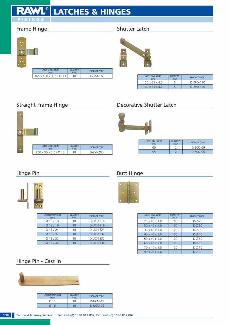
130 Technical Advisory Service Tel: +44 (0) 1530 812 857, Fax: +44 (0) 1530 812 862
LATCHES & HINGES
Shutter Latch
LATCH DIMENSION(mm)
QUANTITYPACK PRODUCT CODE
120 x 65 x 4.0 5 D-ZPO-120140 x 65 x 4.0 5 D-ZPO-140
Decorative Shutter Latch
LATCH DIMENSION(mm)
QUANTITYPACK PRODUCT CODE
60 2 D-ZCO-6095 2 D-ZCO-95
LATCH DIMENSION(mm)
QUANTITYPACK PRODUCT CODE
Ø 10 / 18 10 D-UC-1018Ø 13 / 19 10 D-UC-1319Ø 16 / 24 10 D-UC-1624Ø 10 / 32 10 D-UC-1032Ø 13 / 32 10 D-UC-1332Ø 16 / 34 10 D-UC-1634
Hinge Pin
LATCH DIMENSION(mm)
QUANTITYPACK PRODUCT CODE
25 x 40 x 1.0 100 D-Z-2530 x 40 x 1.0 100 D-Z-3035 x 40 x 1.0 100 D-Z-3540 x 40 x 1.0 100 D-Z-4050 x 40 x 1.0 100 D-Z-5060 x 40 x 1.0 100 D-Z-6070 x 40 x 1.0 100 D-Z-7090 x 90 x 3.0 10 D-Z-90
Butt Hinge
LATCH DIMENSION(mm)
QUANTITYPACK PRODUCT CODE
Ø 13 10 D-UCM-13Ø 16 10 D-UCM-16
Hinge Pin - Cast In
LATCH DIMENSION(mm)
QUANTITYPACK PRODUCT CODE
200 x 90 x 3.0 / Ø 13 10 D-ZM-200
Straight Frame Hinge
LATCH DIMENSION(mm)
QUANTITYPACK PRODUCT CODE
165 x 100 x 3. 0 / Ø 13 10 D-ZMA-165
Frame Hinge
RAWL_KATALOG_2007_2008.indb 130RAWL_KATALOG_2007_2008.indb 130 2007-10-15 14:50:342007-10-15 14:50:34

131Technical Advisory Service e-mail: [email protected] OR [email protected]
WINDOW SCREWS
WINDOW FITTING SCREWS WITH COUNTERSUNK HEAD WITH SELF-TAPPING COARSE THREAD ZINC-PLATED
APPLICATIONFor plastics.
MATERIAL Low carbon steel, electro zinc plated min. 6 �m.
PROPERTISe Countersunk Head Philips2.
SCREW SIZE(mm)
QUANTITYPRODUCT CODE
BOX OUTER
4.0 x 16 1000 24000 KR-4016
4.0 x 19 1000 24000 KR-4019
4.0 x 22 1000 24000 KR-4022
4.0 x 25 1000 24000 KR-4025
4.0 x 30 500 12000 KR-4030
4.0 x 35 500 12000 KR-4035
4.0 x 40 500 6000 KR-4040
4.0 x 45 500 6000 KR-4045
4.0 x 55 500 6000 KR-4055
FOR PLASTIC AND SHEET METAL
SELF-DRILLING WINDOW SCREWS WITH COUNTERSUNK HEAD WITH SELF-TAPPING FINE THREAD ZINC-PLATED
APPLICATIONFor plastics and sheet metal.
MATERIAL Low carbon steel, electro zinc plated min. 6 �m.
PROPERTIESe Milling ribs under head for stressfree embedment, e Drilling capacity (drill tip) 2,5mm,e Countersunk Head Philips2.
SCREW SIZE(mm)
QUANTITYPRODUCT CODE
BOX OUTER
3.9 x 13 1000 24000 KS-3913
3.9 x 16 1000 24000 KS-3916
3.9 x 19 1000 24000 KS-3919
3.9 x 25 1000 24000 KS-3925
3.9 x 32 500 12000 KS-3932
3.9 x 38 500 6000 KS-3938
Product Information
RAWL_KATALOG_2007_2008.indb 131RAWL_KATALOG_2007_2008.indb 131 2007-10-15 14:50:422007-10-15 14:50:42
132 Technical Advisory Service Tel: +44 (0) 1530 812 857, Fax: +44 (0) 1530 812 862
WAFER HEAD SCREWS ELECTRO ZINC PLATED
SCREW SIZE(mm)
QUANTITYPRODUCT CODE
BOX OUTER
4,2 x 13 1000 24000 WF-4213
4,2 x 16 1000 24000 WF-4216
4,2 x 19 500 12000 WF-4219
4,2 x 22 500 12000 WF-4222
4,2 x 25 500 12000 WF-4225
4,2 x 32 500 12000 WF-4232
4,2 x 40 500 6000 WF-4240
4,2 x 52 500 6000 WF-4252
4,2 x 52 250 3000 WF-4265
4,2 x 75 250 3000 WF-4275
Product Information
WAFER HEAD SCREWS
APPLICATION for thin sheet metal, plastics and timber.
MATERIAL low carbon steel, electro zinc plated min. 6 �m.
PROPERTIESe Washer head 11 diameter mm with PH2 recess.
WAFER HEAD SELF DRILLING SCREWS ELECTRO ZINC PLATED
SCREW SIZE(mm)
QUANTITYPRODUCT CODE
BOX OUTER
4,2 x 13 1000 24000 WFS-4213
4,2 x 16 1000 24000 WFS-4216
4,2 x 19 500 12000 WFS-4219
4,2 x 22 500 12000 WFS-4222
4,2 x 25 500 12000 WFS-4225
APPLICATION for thin sheet metal, plastics and timber.
MATERIAL low carbon steel, electro zinc plated min. 6 �m.
PROPERTIESe Washer head 11 diameter mm with PH2 recess.e Drilling capacity (drill tip length) 2,0 mm.
RAWL_KATALOG_2007_2008.indb 132RAWL_KATALOG_2007_2008.indb 132 2007-10-15 14:50:452007-10-15 14:50:45

133Technical Advisory Service e-mail: [email protected] OR [email protected]
CHIPBOARD SCREWS FOR TIMBER, CHIPBOARD, PLASTICS
Product Information
SCREW SIZE DESCRIPTIONQUANTITY
PRODUCT CODEBOX OUTER
5.0 x 20 Pozidrive2 Full Thread 200 9600 UC-50205.0 x 25 Pozidrive2 Full Thread 200 4800 UC-50255.0 x 30 Pozidrive2 Full Thread 200 4800 UC-50305.0 x 35 Pozidrive2 Full Thread 200 4800 UC-50355.0 x 40 Pozidrive2 Full Thread 200 4800 UC-50405.0 x 45 Pozidrive2 Full Thread 200 4800 UC-50455.0 x 50 Pozidrive2 Full Thread 200 4800 UC-50505.0 x 60 Pozidrive2 Partial Thread 100 2400 UC-50605.0 x 70 Pozidrive2 Partial Thread 100 2400 UC-50705.0 x 80 Pozidrive2 Partial Thread 100 2400 UC-50805.0 x 90 Pozidrive2 Partial Thread 100 1200 UC-50905.0 x 100 Pozidrive2 Partial Thread 100 1200 UC-51005.0 x 120 Pozidrive2 Partial Thread 100 1200 UC-51206.0 x 30 Pozidrive3 Full Thread 200 4800 UC-60306.0 x 35 Pozidrive3 Full Thread 200 4800 UC-60356.0 x 40 Pozidrive3 Full Thread 200 4800 UC-60406.0 x 45 Pozidrive3 Full Thread 200 4800 UC-60456.0 x 50 Pozidrive3 Full Thread 200 2400 UC-60506.0 x 60 Pozidrive3 Partial Thread 100 2400 UC-60606.0 x 70 Pozidrive3 Partial Thread 100 1200 UC-60706.0 x 80 Pozidrive3 Partial Thread 100 1200 UC-60806.0 x 90 Pozidrive3 Partial Thread 100 1200 UC-60906.0 x 100 Pozidrive3 Partial Thread 100 1200 UC-61006.0 x 110 Pozidrive3 Partial Thread 100 1200 UC-61106.0 x 120 Pozidrive3 Partial Thread 100 1200 UC-61206.0 x 130 Pozidrive3 Partial Thread 100 1200 UC-61306.0 x 140 Pozidrive3 Partial Thread 100 1200 UC-61406.0 x 150 Pozidrive3 Partial Thread 100 1200 UC-61506.0 x 160 Pozidrive3 Partial Thread 100 1200 UC-61606.0 x 180 Pozidrive3 Partial Thread 100 1200 UC-61806.0 x 200 Pozidrive3 Partial Thread 100 1200 UC-6200
APPLICATION For screwing into chipboard, timber, plastics with no pre-drilling.
MATERIAL Low carbon steel, electro zinc plated min. 6 �m.
PROPERTIESe Milling cross notches on the thread ease installation (easy screwing
through cutting into even very hard materials),
SCREW SIZE SCREW HEAD DESCRIPTIONQUANTITY
PRODUCT CODEBOX OUTER
2.5 x 16 Pozidrive1 Full Thread 200 9600 UC-25163.0 x 12 Pozidrive1 Full Thread 200 9600 UC-30123.0 x 16 Pozidrive1 Full Thread 200 9600 UC-30163.0 x 18 Pozidrive1 Full Thread 200 9600 UC-30183.0 x 20 Pozidrive1 Full Thread 200 9600 UC-30203.0 x 25 Pozidrive1 Full Thread 200 9600 UC-30253.0 x 30 Pozidrive1 Full Thread 200 9600 UC-30303.0 x 35 Pozidrive1 Full Thread 200 9600 UC-30353.0 x 40 Pozidrive1 Full Thread 200 4800 UC-30403.5 x 12 Pozidrive2 Full Thread 200 9600 UC-35123.5 x 16 Pozidrive2 Full Thread 200 9600 UC-35163.5 x 18 Pozidrive2 Full Thread 200 9600 UC-35183.5 x 20 Pozidrive2 Full Thread 200 9600 UC-35203.5 x 25 Pozidrive2 Full Thread 200 9600 UC-35253.5 x 30 Pozidrive2 Full Thread 200 9600 UC-35303.5 x 35 Pozidrive2 Full Thread 200 4800 UC-35353.5 x 40 Pozidrive2 Full Thread 200 4800 UC-35403.5 x 45 Pozidrive2 Full Thread 200 4800 UC-35453.5 x 50 Pozidrive2 Full Thread 200 4800 UC-35504.0 x 16 Pozidrive2 Full Thread 200 9600 UC-40164.0 x 18 Pozidrive2 Full Thread 200 9600 UC-40184.0 x 20 Pozidrive2 Full Thread 200 9600 UC-40204.0 x 25 Pozidrive2 Full Thread 200 9600 UC-40254.0 x 30 Pozidrive2 Full Thread 200 4800 UC-40304.0 x 35 Pozidrive2 Full Thread 200 4800 UC-40354.0 x 40 Pozidrive2 Full Thread 200 4800 UC-40404.0 x 45 Pozidrive2 Full Thread 200 4800 UC-40454.0 x 50 Pozidrive2 Full Thread 200 4800 UC-40504.0 x 55 Pozidrive2 Full Thread 200 4800 UC-40554.0 x 60 Pozidrive2 Partial Thread 200 4800 UC-40604.0 x 70 Pozidrive2 Partial Thread 200 3600 UC-40704.0 x 80 Pozidrive2 Partial Thread 200 2400 UC-40804.5 x 16 Pozidrive2 Full Thread 200 9600 UC-45164.5 x 20 Pozidrive2 Full Thread 200 9600 UC-45204.5 x 25 Pozidrive2 Full Thread 200 9600 UC-45254.5 x 30 Pozidrive2 Full Thread 200 4800 UC-45304.5 x 35 Pozidrive2 Full Thread 200 4800 UC-45354.5 x 40 Pozidrive2 Full Thread 200 4800 UC-45404.5 x 45 Pozidrive2 Full Thread 200 4800 UC-45454.5 x 50 Pozidrive2 Full Thread 200 4800 UC-45504.5 x 60 Pozidrive2 Partial Thread 200 3600 UC-45604.5 x 70 Pozidrive2 Partial Thread 200 3600 UC-45704.5 x 80 Pozidrive2 Partial Thread 200 2400 UC-4580
CHIPBOARD SCREWS WITH CROSS-SLOT ON THE THREAD
RAWL_KATALOG_2007_2008.indb 133RAWL_KATALOG_2007_2008.indb 133 2007-10-15 14:50:462007-10-15 14:50:46

134 Technical Advisory Service Tel: +44 (0) 1530 812 857, Fax: +44 (0) 1530 812 862
Masonry Nails
DESCRIPTIONFast, penetrating and virtually shatterproof.
SUITABLE FOR USE IN:Masonry.
FEATURES1. Head shape prevents hammer slide and gives a neat flush fixing.2. Zinc plated.3. Special heat treatment to provide required hardness.4. Washer version for increased clamping force.5. Point shape minimises timber splitting.
Installation
1. Place nail in position and hammer in.
Always wear suitable eye protection to BS EN166.
Product Information
NAIL DIMMENSION(mm) OPTIONS QUANTITY
BOX PACK
PRODUCT CODE NEW CODE PRODUCT CODE NEW CODE
2.5 x 25 Without Washer 40 04-102 MNL-25025-10/402.5 x 25 Without Washer 100 04-002 MNL-250252.5 x 30 Without Washer 40 04-104 MNL-25025-10/402.5 x 30 Without Washer 100 04-004 MNL-250302.5 x 35 Without Washer 100 04-006 MNL-250352.5 x 40 Without Washer 30 04-009 MNL-25045-10/302.5 x 40 Without Washer 100 04-008 MNL-250402.5 x 50 Without Washer 100 04-012 MNL-250503.0 x 40 Without Washer 100 04-020 MNL-300403.0 x 50 Without Washer 30 04-124 MNL-25025-10/303.0 x 50 Without Washer 100 04-024 MNL-300503.0 x 60 Without Washer 20 04-126 MNL-25025-10/203.0 x 60 Without Washer 100 04-026 MNL-300603.0 x 65 Without Washer 100 04-028 MNL-300653.5 x 75 Without Washer 10 04-138 MNL-25025-10/103.5 x 75 Without Washer 100 04-038 MNL-350753.5 x 85 Without Washer 100 04-040 MNL-350853.5 x 100 Without Washer 6 04-142 MNL-25025-10/063.5 x 100 Without Washer 100 04-042 MNL-351003.7 x 25 With Washer 100 04-044 MNL-W-370253.7 x 30 With Washer 100 04-046 MNL-W-370303.7 x 35 With Washer 100 04-048 MNL-W-370353.7 x 40 With Washer 100 04-050 MNL-W-370403.7 x 50 With Washer 100 04-052 MNL-W-37050
MASONRY NAILSFOR MASONRY
TYPICAL APPLICATIONSe Suitable for a wide range of fixtures
into masonry including battering & boarding.
RAWL_KATALOG_2007_2008.indb 134RAWL_KATALOG_2007_2008.indb 134 2007-10-15 14:50:532007-10-15 14:50:53

135Technical Advisory Service e-mail: [email protected] OR [email protected]
PLUG & REPAIR / FIX & FORGET
Product Information
Plug & Repair
DESCRIPTIONQuick-setting epoxy putty provides secure fixing in damaged or uneven holes.
SUITABLE FOR USE IN:Wood, Brickwork, Plastic, Metal & Plasterboard.
FEATURES1. Tear-off epoxy resin strip.2. Mixes in seconds by hand.3. Can be sanded, drilled or filed,
to a white finish, when hard.4. Hardens in 15-20 minutes.
Accepts standard woodscrew.
TYPICAL APPLICATIONSe Fills and plugs uneven holese Correcting badly drilled
holes for fixings
How to use
1. Ensure all surfaces are clean and free from grease and dust.
2. Remove protective film and break off a strip of Plug & Repair. In hot weather run under cold water to ease removal of plastic film.
3. Mix by hand, folding, twisting and kneading thoroughly until blue
pigment fades to white (wetting fingers improves workability).
4. Apply firmly to repair area and create a pilot hole (approx. 3mm deep) with a screw to ensure accurate location of the fixture.
5. After 15-20 minutes, position the fixture and, using a screwdriver,
insert a screw, driving it firmly home.
6. Plug & Repair can be drilled, sanded or filed after 30 minutes.
DESCRIPTIONPACK
PRODUCT CODE NEW CODE
18 cm TAPE 13-002 PAR-18
60 cm TAPE 13-010 PAR-60
Wear suitable protective gloves.
DESCRIPTIONWorks on virtually any material.
WRC approved for use with drinking water.
SUITABLE FOR USE IN:Wood, Brickwork, Plastic, Metal, Plasterboard and Fibreglass.
FEATURES1. Fast and easy to use putty. Sets
steel hard in minutes. Even sets under water.
2. Provides a permanent repair, which is waterproof, heat resistant, and electrically insulating.
3. Can be drilled, tapped, filed, screwed, sawn, sanded, painted and machined.
TYPICAL APPLICATIONSe Repairing damaged screw
holese Repairs to plastic or metal
pipes, baths, sinks and water tanks
e Repair for gutters, boats, caravans, plastic garden furniture etc.
Product Information
Fix & Forget
How to use
1. Ensure all surfaces are clean and free from grease and dust.
2. Cut off the required amount to fill hole, using scissors or a sharp knife. Peel off protective wrapping.
3. Mix by hand, wearing protective gloves, folding twisting and kneading thoroughly
until the colour changes to an even white.4. Apply firmly to the repair area. Clean off
surplus material using a wet knife. Allow an hour to cure.
5. Fix & Forget can then be sawn, drilled, sanded, screwed, carved and painted.
DESCRIPTIONPACK
PRODUCT CODE NEW CODE
12 cm STICK 13-200 PAR-FIX
Wear suitable protective gloves.
RAWL_KATALOG_2007_2008.indb 135RAWL_KATALOG_2007_2008.indb 135 2007-10-15 14:50:542007-10-15 14:50:54

136 Technical Advisory Service Tel: +44 (0) 1530 812 857, Fax: +44 (0) 1530 812 862
PLASTIC WOOD/FLOOR FILLER
Product Information
Plastic Wood
How to use
1. Ensure area to be filled is clean and dry.2. Apply Plastic Wood using a wet filling knife
to avoid drag.
3. Slightly overfill the hole so that the repair stands proud of the surrounding surface.
4. When the repair is fully set, rub down with abrasive paper for a perfect finish.
NB: Deep holes should be filled in successive layers allowing each layer time to dry before the next is added.
DESCRIPTION50 ml TUBE 100ml TUBE 250 ml TUBE 310ml CARTRIDGE
PRODUCT CODE PRODUCT CODE PRODUCT CODE PRODUCT CODE
MAHOGANY PLW-MH050 PLW-MH100 PLW-MH250 PLW-MH310
OAK PLW-OA050 PLW-OA100 PLW-OA250 PLW-OA310
PINE PLW-PN050 PLW-PN100 PLW-PN250 PLW-PN310
TEAK PLW-TK050 PLW-TK100 PLW-TK250 PLW-TK310
TYPICAL APPLICATIONSe Furniture and framese Filling cracks or chips in timbere Repairing skirting boards and
decorative woodworke Can be drilled, sanded and
stained if required
DESCRIPTIONFor minor repairs to wood, inside and outside.
FEATURESe Colours can be mixed.e Durable & water resistant.
e Accepts screws and nails.e Available in a comprehensive
range of popular wood shades to match natural timber.
e Solvent free, low odour.
Pine Teak Mahogany OakThe above colour chart is for reference only, a perfect colour match cannot be guaranteed.
Floor Filler
TYPICAL APPLICATIONSe Sealing around awkward
protrusions eg. radiations pipes.
e Sealing around fitted furniture.
DESCRIPTIONFor timber and laminate floors.
FEATURESe With reinforced polymer for
added strenth.e Available colors: Pine, Oak, Beech.
DESCRIPTION310ml CARTRIDGE
PRODUCT CODE
BEECH FLF-BE310
OAK FLF-OA310
PINE FLF-PN310
Product Information
RAWL_KATALOG_2007_2008.indb 136RAWL_KATALOG_2007_2008.indb 136 2007-10-15 14:50:562007-10-15 14:50:56
137Technical Advisory Service e-mail: [email protected] OR [email protected]
LIQUID FIXING/GRIPFAST® BUILDING ADHESIVES
FOR WOOD, BRICKWORK, PLASTIC, METAL & PLASTERBOARD
TYPICAL APPLICATIONSe Fixing timber, metal and
PVCu door and window frames
e Fixing timber battens, soffits, fascias and barge boards
e For metal and PVCu cladding etc.
DESCRIPTION High performance multi-purpose building adhesive.Ideal for a wide range of external applications.
SUITABLE FOR USE IN:Wood, Brickwork, Plastic, Metal & Plasterboard.
FEATURES1. Exceptional early grab.2. Frost and rain resistant: ideal for external use.3. Suitable for use where both surfaces are nonporous.4. Fills gaps in uneven surfaces.5. Cartridge fits any standard mastic gun.
DESCRIPTION310ml CARTRIDGE
PRODUCT CODE NEW CODE
SOLVENT BASED ADHESIVE 61-010 R-GRIPFAST-SB
Product Information
GRIPFAST
TYPICAL APPLICATIONSe Skirting boardse Dado railse Battense Mouldingse Architravese Carpetse Tiles
DESCRIPTIONHigh strength, fast curing multi-purpose adhesive.Solvent free and low odour: ideal for both indoor and outdoor use.
SUITABLE FOR USE IN:Wood, Brickwork, Plastic, Metal, Plasterboard, Glass and Ceramics.
FEATURES1. Fast grab for easy fixing.2. Extended open time for easy repositioning.3. Fills small gaps in uneven surfaces.4. Cartridge fits any standard mastic gun.
DESCRIPTION310ml CARTRIDGE
PRODUCT CODE NEW CODE
SOLVENT FREE ADHESIVE 61-001 R-LIQFIX-SF
Product Information
LIQUID FIXING
RAWL_KATALOG_2007_2008.indb 137RAWL_KATALOG_2007_2008.indb 137 2007-10-15 14:51:032007-10-15 14:51:03

138 Technical Advisory Service Tel: +44 (0) 1530 812 857, Fax: +44 (0) 1530 812 862
Cable Clips “Flop” - Assembled With Nails For Fixing Of Round Cables
CABLE DIAMETER(mm)
NAIL DIMMENSIONS(mm)
QUANTITYPRODUCT CODE
BLISTER OUTER
3 - 6 1.4 x 20 16 1024 B-FLO-F0
6 - 9 2.0 x 25 16 1024 B-FLO-F1
9 - 13 2.0 x 30 8 256 B-FLO-F2
13 - 18 2.5 x 37 8 256 B-FLO-F3
18 - 24 2,5 x 42 8 256 B-FLO-F4
CABLE CLIPS
Product Information
Cable Clips Assembled With Nails For Fixing Flat Twin and Earth
CABLE DIMMENSIONS (mm)
NAIL DIMMENSIONS(mm)
QUANTITYPRODUCT CODE
BLISTER OUTER
3 x 5 1.5 x 20 60 3840 B-FLO-P3/5
4 x 6 1.8 x 20 30 1920 B-FLO-P4/6
5 x 8 1.8 x 24 25 800 B-FLO-P5/8
5 x 9 1.8 x 24 25 800 B-FLO-P5/9
6 x 10 1.8 x 24 20 640 B-FLO-P6/10
6 x 13 1.8 x 25 20 640 B-FLO-P6/13
Cable Clips Assembled With Nails For Fixing Of Round Cables And Pipes
CABLE DIAMETER(mm)
NAIL DIMMENSIONS(mm)
QUANTITYPRODUCT CODE
BLISTER OUTER
22 - 24 2.5 x 42 8 256 B-FLO-U22
26 - 28 2.5 x 50 12 1920 B-FLO-U26
Expansion Plugs For Clips With Nail
HOLE DIAMETER(mm)
NAIL LENGTH(mm)
QUANTITYPRODUCT CODE
BLISTER OUTER
6.0 22 35 560 B-FLO-K06
RAWL_KATALOG_2007_2008.indb 138RAWL_KATALOG_2007_2008.indb 138 2007-10-15 14:51:072007-10-15 14:51:07
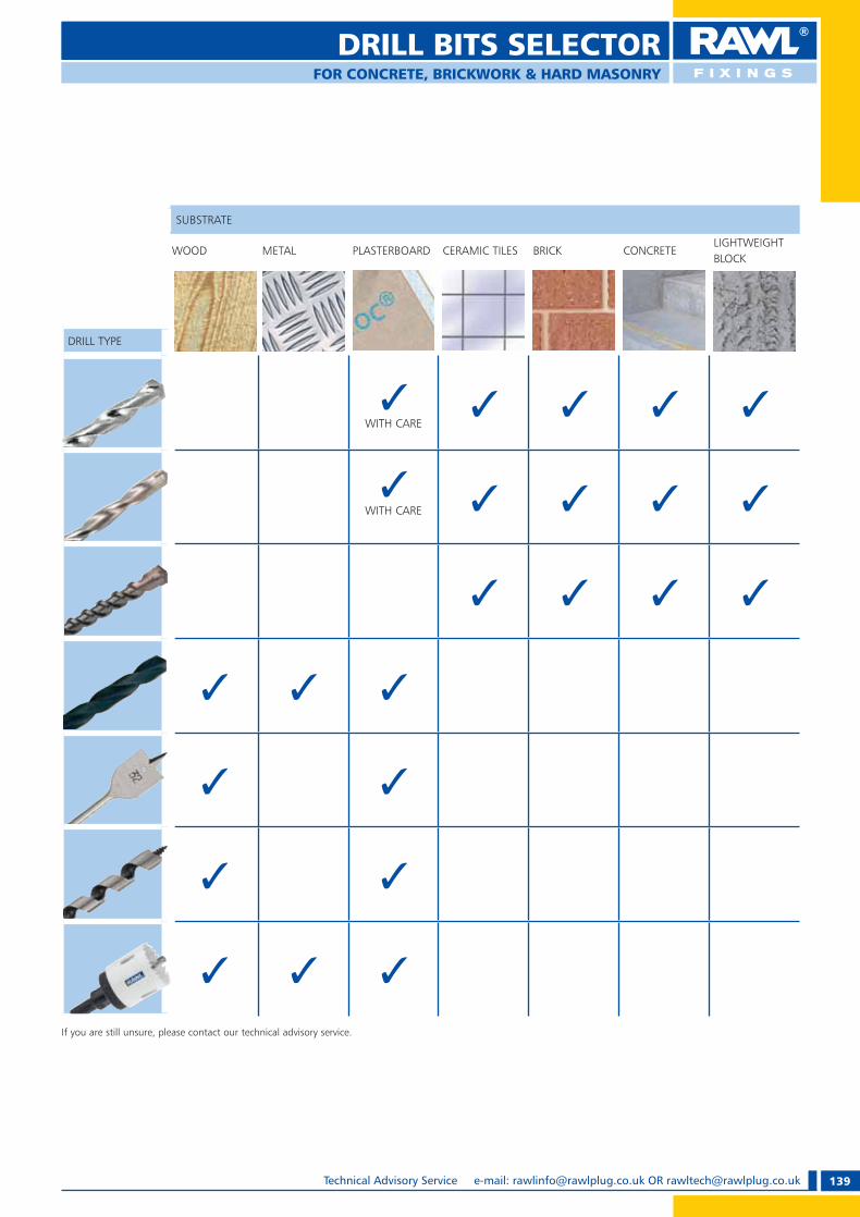
139Technical Advisory Service e-mail: [email protected] OR [email protected]
SUBSTRATE
WOOD METAL PLASTERBOARD CERAMIC TILES BRICK CONCRETELIGHTWEIGHT BLOCK
DRILL TYPE
�WITH CARE
� � � �
�WITH CARE � � � �
� � � �
� � �
� �
� �
� � �
If you are still unsure, please contact our technical advisory service.
DRILL BITS SELECTORFOR CONCRETE, BRICKWORK & HARD MASONRY
RAWL_KATALOG_2007_2008.indb 139RAWL_KATALOG_2007_2008.indb 139 2007-10-15 14:51:232007-10-15 14:51:23
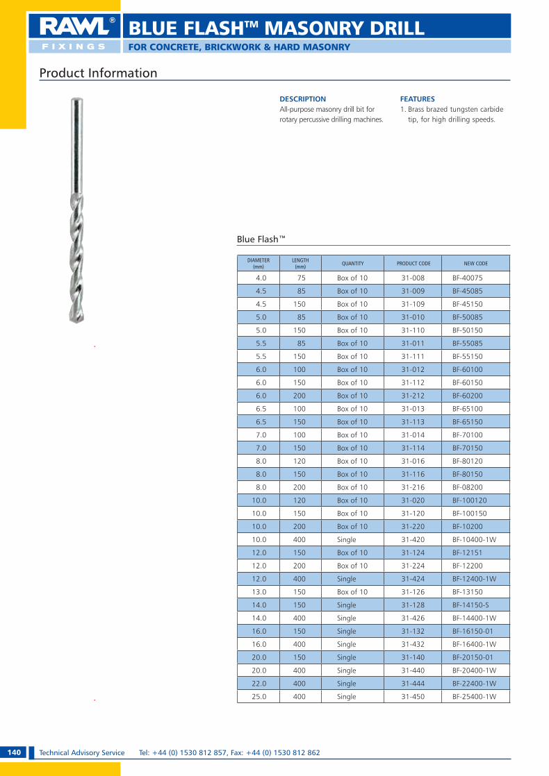
140 Technical Advisory Service Tel: +44 (0) 1530 812 857, Fax: +44 (0) 1530 812 862
Product Information
DESCRIPTIONAll-purpose masonry drill bit for rotary percussive drilling machines.
FEATURES1. Brass brazed tungsten carbide
tip, for high drilling speeds.
BLUE FLASHTM MASONRY DRILL
FOR CONCRETE, BRICKWORK & HARD MASONRY
DIAMETER(mm)
LENGTH(mm) QUANTITY PRODUCT CODE NEW CODE
4.0 75 Box of 10 31-008 BF-40075
4.5 85 Box of 10 31-009 BF-45085
4.5 150 Box of 10 31-109 BF-45150
5.0 85 Box of 10 31-010 BF-50085
5.0 150 Box of 10 31-110 BF-50150
5.5 85 Box of 10 31-011 BF-55085
5.5 150 Box of 10 31-111 BF-55150
6.0 100 Box of 10 31-012 BF-60100
6.0 150 Box of 10 31-112 BF-60150
6.0 200 Box of 10 31-212 BF-60200
6.5 100 Box of 10 31-013 BF-65100
6.5 150 Box of 10 31-113 BF-65150
7.0 100 Box of 10 31-014 BF-70100
7.0 150 Box of 10 31-114 BF-70150
8.0 120 Box of 10 31-016 BF-80120
8.0 150 Box of 10 31-116 BF-80150
8.0 200 Box of 10 31-216 BF-08200
10.0 120 Box of 10 31-020 BF-100120
10.0 150 Box of 10 31-120 BF-100150
10.0 200 Box of 10 31-220 BF-10200
10.0 400 Single 31-420 BF-10400-1W
12.0 150 Box of 10 31-124 BF-12151
12.0 200 Box of 10 31-224 BF-12200
12.0 400 Single 31-424 BF-12400-1W
13.0 150 Box of 10 31-126 BF-13150
14.0 150 Single 31-128 BF-14150-S
14.0 400 Single 31-426 BF-14400-1W
16.0 150 Single 31-132 BF-16150-01
16.0 400 Single 31-432 BF-16400-1W
20.0 150 Single 31-140 BF-20150-01
20.0 400 Single 31-440 BF-20400-1W
22.0 400 Single 31-444 BF-22400-1W
25.0 400 Single 31-450 BF-25400-1W
Blue Flash™
RAWL_KATALOG_2007_2008.indb 140RAWL_KATALOG_2007_2008.indb 140 2007-10-15 14:51:482007-10-15 14:51:48
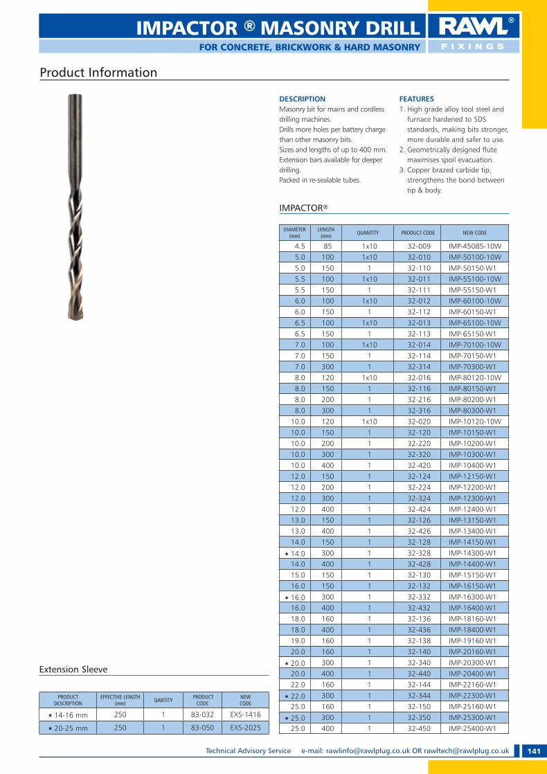
141Technical Advisory Service e-mail: [email protected] OR [email protected]
Product Information
DESCRIPTIONMasonry bit for mains and cordless drilling machines. Drills more holes per battery charge than other masonry bits.Sizes and lengths of up to 400 mm.Extension bars available for deeper drilling. Packed in re-sealable tubes.
FEATURES1. High grade alloy tool steel and
furnace hardened to SDS standards, making bits stronger, more durable and safer to use.
2. Geometrically designed flute maximises spoil evacuation.
3. Copper brazed carbide tip, strengthens the bond between tip & body.
DIAMETER(mm)
LENGTH(mm) QUANTITY PRODUCT CODE NEW CODE
4.5 85 1x10 32-009 IMP-45085-10W5.0 100 1x10 32-010 IMP-50100-10W5.0 150 1 32-110 IMP-50150-W15.5 100 1x10 32-011 IMP-55100-10W5.5 150 1 32-111 IMP-55150-W16.0 100 1x10 32-012 IMP-60100-10W6.0 150 1 32-112 IMP-60150-W16.5 100 1x10 32-013 IMP-65100-10W6.5 150 1 32-113 IMP-65150-W17.0 100 1x10 32-014 IMP-70100-10W7.0 150 1 32-114 IMP-70150-W17.0 300 1 32-314 IMP-70300-W18.0 120 1x10 32-016 IMP-80120-10W8.0 150 1 32-116 IMP-80150-W18.0 200 1 32-216 IMP-80200-W18.0 300 1 32-316 IMP-80300-W1
10.0 120 1x10 32-020 IMP-10120-10W10.0 150 1 32-120 IMP-10150-W110.0 200 1 32-220 IMP-10200-W110.0 300 1 32-320 IMP-10300-W110.0 400 1 32-420 IMP-10400-W112.0 150 1 32-124 IMP-12150-W112.0 200 1 32-224 IMP-12200-W112.0 300 1 32-324 IMP-12300-W112.0 400 1 32-424 IMP-12400-W113.0 150 1 32-126 IMP-13150-W113.0 400 1 32-426 IMP-13400-W114.0 150 1 32-128 IMP-14150-W1
u 14.0 300 1 32-328 IMP-14300-W114.0 400 1 32-428 IMP-14400-W115.0 150 1 32-130 IMP-15150-W116.0 150 1 32-132 IMP-16150-W1
u 16.0 300 1 32-332 IMP-16300-W116.0 400 1 32-432 IMP-16400-W118.0 160 1 32-136 IMP-18160-W118.0 400 1 32-436 IMP-18400-W119.0 160 1 32-138 IMP-19160-W120.0 160 1 32-140 IMP-20160-W1
u 20.0 300 1 32-340 IMP-20300-W120.0 400 1 32-440 IMP-20400-W122.0 160 1 32-144 IMP-22160-W1
u 22.0 300 1 32-344 IMP-22300-W125.0 160 1 32-150 IMP-25160-W1
u 25.0 300 1 32-350 IMP-25300-W125.0 400 1 32-450 IMP-25400-W1
PRODUCT DESCRIPTION
EFFECTIVE LENGTH(mm) QANTITY PRODUCT
CODENEW CODE
u 14-16 mm 250 1 83-032 EXS-1416
u 20-25 mm 250 1 83-050 EXS-2025
IMPACTOR ® MASONRY DRILLFOR CONCRETE, BRICKWORK & HARD MASONRY
IMPACTOR®
Extension Sleeve
RAWL_KATALOG_2007_2008.indb 141RAWL_KATALOG_2007_2008.indb 141 2007-10-15 14:51:522007-10-15 14:51:52

142 Technical Advisory Service Tel: +44 (0) 1530 812 857, Fax: +44 (0) 1530 812 862
SDS
DESCRIPTIONDeveloped for SDS rotary hammer drilling machines.Provides faster, easier drilling with lower power consumption.
FEATURES1. Twin spiral shank for fast,
effective, clearance of spoil.2. Specially designed tip
outperforms other brands for performance and longevity.
3. Can be extended with SDS extension sleeves in conjunction with impactor drill range marked.
Product Information
DIAMETER(mm)
LENGTH(mm) PRODUCT CODE NEW CODE
4.0 110 34-006 SDS-40110
5.0 110 34-010 SDS-50110
5.0 160 34-110 SDS-50160
5.5 110 34-011 SDS-55110
5.5 160 34-111 SDS-55160
6.0 110 34-012 SDS-60110
6.0 160 34-112 SDS-60160
6.0 210 34-210 SDS-60210
6.5 110 34-013 SDS-65110
6.5 160 34-113 SDS-65160
6.5 210 34-212 SDS-65210
7.0 110 34-014 SDS-70110
7.0 160 34-114 SDS-70160
7.0 210 34-214 SDS-70210
8.0 110 34-016 SDS-80110
8.0 160 34-116 SDS-80160
8.0 210 34-216 SDS-80210
8.0 260 34-318 SDS-80260
9.0 210 34-218 SDS-90210
10.0 110 34-020 SDS-100110
10.0 160 34-120 SDS-10160
10.0 260 34-320 SDS-10260
10.0 310 34-380 SDS-10310
10.0 450 34-420 SDS-10450
10.0 600 34-520 SDS-10600
11.0 310 34-382 SDS-11310
12.0 160 34-124 SDS-12160
12.0 250 34-324 SDS-12250
12.0 300 34-384 SDS-12300
12.0 450 34-424 SDS-12450
12.0 1000 34-586 SDS-121000
13.0 150 34-126 SDS-13150
13.0 250 34-326 SDS-13250
13.0 450 34-426 SDS-13450
SDS plus MASONRY DRILLFOR STRUCTUAL CONCRETE & ENGINEERING BRICK
DIAMETER(mm)
LENGTH(mm) PRODUCT CODE NEW CODE
14.0 150 34-128 SDS-14150
14.0 200 34-230 SDS-14200
14.0 250 34-328 SDS-14250
14.0 300 34-388 SDS-14300
14.0 450 34-428 SDS-14450
15.0 150 34-130 SDS-15150
15.0 250 34-330 SDS-15250
16.0 150 34-132 SDS-16150
16.0 200 34-232 SDS-16200
16.0 300 34-390 SDS-16300
16.0 450 34-432 SDS-16450
16.0 600 34-532 SDS-16600
16.0 800 34-538 SDS-16800
18.0 200 34-236 SDS-18200
18.0 300 34-392 SDS-18300
18.0 450 34-436 SDS-18450
18.0 600 34-536 SDS-18600
18.0 1000 34-592 SDS-181000
20.0 200 34-240 SDS-20200
20.0 450 34-440 SDS-20450
20.0 600 34-540 SDS-20600
20.0 1000 34-594 SDS-201000
22.0 250 34-344 SDS-22250
22.0 450 34-442 SDS-22450
22.0 1000 34-596 SDS-221000
24.0 250 34-348 SDS-24250
24.0 450 34-448 SDS-24450
25.0 250 34-350 SDS-25260
25.0 450 34-450 SDS-25450
25.0 600 34-550 SDS-25600
26.0 450 34-452 SDS-26450
RAWL_KATALOG_2007_2008.indb 142RAWL_KATALOG_2007_2008.indb 142 2007-10-15 14:51:572007-10-15 14:51:57
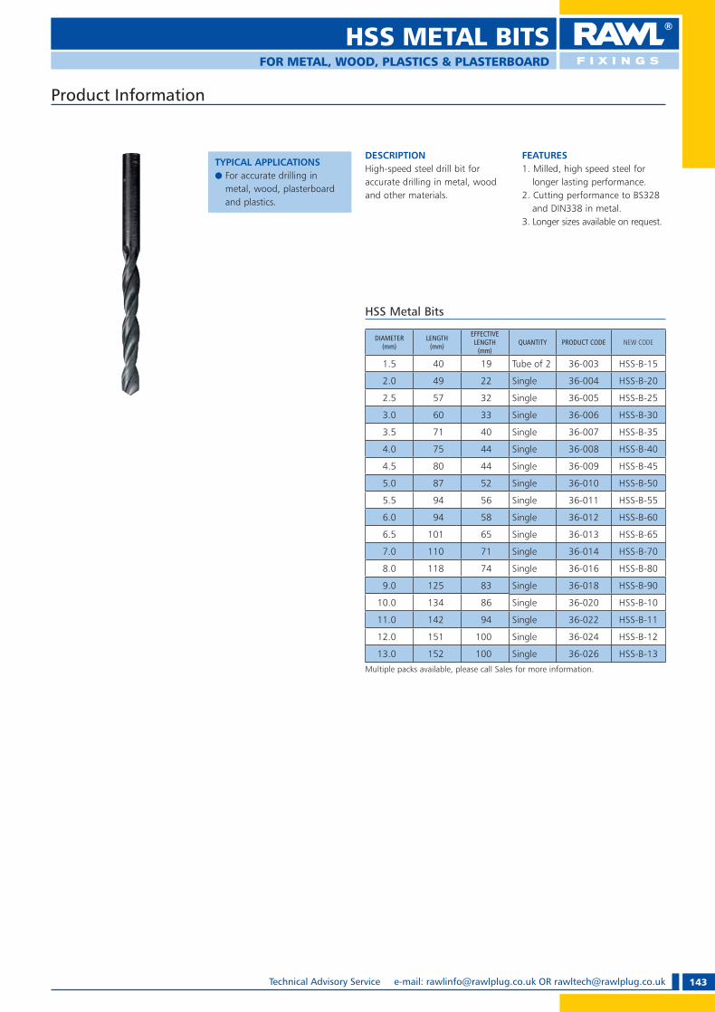
143Technical Advisory Service e-mail: [email protected] OR [email protected]
HSS METAL BITSFOR METAL, WOOD, PLASTICS & PLASTERBOARD
DESCRIPTIONHigh-speed steel drill bit for accurate drilling in metal, wood and other materials.
FEATURES1. Milled, high speed steel for
longer lasting performance.2. Cutting performance to BS328
and DIN338 in metal.3. Longer sizes available on request.
HSS Metal Bits
DIAMETER(mm)
LENGTH(mm)
EFFECTIVE LENGTH
(mm)QUANTITY PRODUCT CODE NEW CODE
1.5 40 19 Tube of 2 36-003 HSS-B-15
2.0 49 22 Single 36-004 HSS-B-20
2.5 57 32 Single 36-005 HSS-B-25
3.0 60 33 Single 36-006 HSS-B-30
3.5 71 40 Single 36-007 HSS-B-35
4.0 75 44 Single 36-008 HSS-B-40
4.5 80 44 Single 36-009 HSS-B-45
5.0 87 52 Single 36-010 HSS-B-50
5.5 94 56 Single 36-011 HSS-B-55
6.0 94 58 Single 36-012 HSS-B-60
6.5 101 65 Single 36-013 HSS-B-65
7.0 110 71 Single 36-014 HSS-B-70
8.0 118 74 Single 36-016 HSS-B-80
9.0 125 83 Single 36-018 HSS-B-90
10.0 134 86 Single 36-020 HSS-B-10
11.0 142 94 Single 36-022 HSS-B-11
12.0 151 100 Single 36-024 HSS-B-12
13.0 152 100 Single 36-026 HSS-B-13
Multiple packs available, please call Sales for more information.
Product Information
TYPICAL APPLICATIONSe For accurate drilling in
metal, wood, plasterboard and plastics.
RAWL_KATALOG_2007_2008.indb 143RAWL_KATALOG_2007_2008.indb 143 2007-10-15 14:52:032007-10-15 14:52:03

144 Technical Advisory Service Tel: +44 (0) 1530 812 857, Fax: +44 (0) 1530 812 862
DESCRIPTIONFor rapid drilling of large diameter holes in wood.
FEATURESExtension rods available for 16-32mm sizes to extend drilling depth by 260 mm each.
Product Information
TYPICAL APPLICATIONSe Designed for use with rotary
action power drills. Ideal for hard or soft woods, chipboard etc.
Flat Wood Bits
DIAMETER(mm)
LENGTH(mm)
EFFECTIVE LENGTH
(mm)QUANTITY PRODUCT CODE NEW CODE
6.5 150 110 Pack of 5 70-013 FLB-0655/01
8.0 150 110 Pack of 5 70-016 FLB-0805/01
10.0 150 110 Pack of 5 70-020 FLB-1005/01
13.0 150 110 Pack of 5 70-026 FLB-1305/01
14.0 150 110 Pack of 5 70-028 FLB-1405/01
16.0 150 110 Pack of 5 70-032 FLB-1605/01
18.0 150 110 Pack of 5 70-036 FLB-1805/01
20.0 150 110 Pack of 5 70-040 FLB-2005/01
22.0 150 110 Pack of 5 70-044 FLB-2205/01
25.0 150 110 Pack of 5 70-050 FLB-2505/01
28.0 150 110 Pack of 5 70-056 FLB-2805/01
32.0 150 110 Pack of 5 70-064 FLB-3205/01
Extension 300 260 Pack of 5 70-200 FLB-ES
DESCRIPTIONFor drilling in all types of wood.
FEATURES1. Hardened, tempered carbon steel
retains sharpness and edge.2. Self-feeding screw pulls bit into
wood for precise drilling.3. Open throat & double twist
design for rapid chip clearance.
Product Information
TYPICAL APPLICATIONSe Precision drilling of deep
holes.
Auger Wood Bits
DIAMETER(mm)
LENGTH(mm)
EFFECTIVE LENGTH
(mm)QUANTITY PRODUCT CODE NEW CODE
6.5 200 160 Tube of 1 72-013 AUB-065
8.0 200 160 Tube of 1 72-016 AUB-080
10.0 200 160 Tube of 1 72-020 AUB-100
11.0 200 160 Tube of 1 72-022 AUB-110
13.0 200 160 Tube of 1 72-026 AUB-130
16.0 200 160 Tube of 1 72-032 AUB-160
20.0 200 160 Tube of 1 72-040 AUB-200
22.0 200 160 Tube of 1 72-044 AUB-220
25.0 200 160 Tube of 1 72-050 AUB-250
32.0 200 160 Tube of 1 72-064 AUB-320
FLAT/AUGER WOOD BITSFOR PLASTERBOARD, HARD & SOFT WOODS
RAWL_KATALOG_2007_2008.indb 144RAWL_KATALOG_2007_2008.indb 144 2007-10-15 14:52:052007-10-15 14:52:05

145Technical Advisory Service e-mail: [email protected] OR [email protected]
HOLE SAWFOR MILD STEEL, BRASS, CAST IRON, WOOD & PLASTICS
DESCRIPTIONDiameters 16mm - 152mm.
TIPSPlease observe the recommended cutting speeds depending on material being cut.
FEATURES1. Well engineered base reduces
vibration.2. High speed steel bi-metal
moulded to tough alloy body.3. 4 to 6 variable pitch tooth
design for faster cutting.
Hole Saw
Product Information
TYPICAL APPLICATIONSe Suitable for cutting holes in
mild steel, brass, cast iron, wood and plastics.
e Compatible with all major hole saw and arbor brands.
DIAMETER EFFECTIVE LENGTH(mm) QUANTITY PRODUCT CODE NEW CODE
16 36 Box of 1 16-500 HSW-1619 35 Box of 1 16-504 HSW-1920 38 Box of 1 16-506 HSW-2022 34 Box of 1 16-510 HSW-2225 38 Box of 1 16-514 HSW-2529 35 Box of 1 16-518 HSW-2932 34 Box of 1 16-522 HSW-3235 38 Box of 1 16-526 HSW-3538 35 Box of 1 16-528 HSW-3844 38 Box of 1 16-534 HSW-4451 35 Box of 1 16-540 HSW-5154 38 Box of 1 16-542 HSW-5460 35 Box of 1 16-546 HSW-6064 38 Box of 1 16-548 HSW-6467 38 Box of 1 16-550 HSW-6770 38 Box of 1 16-552 HSW-7073 35 Box of 1 16-554 HSW-7379 38 Box of 1 16-556 HSW-7989 38 Box of 1 16-560 HSW-89
102 38 Box of 1 16-564 HSW-102111 38 Box of 1 16-568 HSW-111114 38 Box of 1 16-570 HSW-114127 38 Box of 1 16-574 HSW-127140 38 Box of 1 16-576 HSW-140152 38 Box of 1 16-578 HSW-152
ARBOR SIZE(mm)
FITS 16-29 mm FITS 32-152 mmQUANTITY
PRODUCT CODE NEW CODE PRODUCT CODE NEW CODE
8 16-600 HSW-08 — — Box of 1
11 — — 16-602 HSW-011 Box of 1
SDS Plus 16-606 HSW-14-SDS 16-608 HSW-32-SDS Box of 1
Arbors
DRILL LENGTH(mm) PRODUCT CODE NEW CODE
72.0 16-610 HSW-P-072
102.0 16-612 HSW-P-102
Pilot Drills
RAWL_KATALOG_2007_2008.indb 145RAWL_KATALOG_2007_2008.indb 145 2007-10-15 14:52:072007-10-15 14:52:07

146 Technical Advisory Service Tel: +44 (0) 1530 812 857, Fax: +44 (0) 1530 812 862
ELECTRIC SCREWDRIVER BIT
Product Information
PROPERTIESe General purpose use insert bits.e High abrasion resistance.e Made from steel S2 of hardness 56-62 HRC.e Milled bit tips in ACR SYSTEM.
Sets
SET COMPONENTS DESCRIPTION OUTER QUANTITY(sets) PRODUCT CODE
5.0 x 0.8; 6.5 x 1.2; Philips 1; Philips 2; Pozi 1; Pozi 2;Magnetic bit holder
6+1 pcs 12 MN-15-501
Philips 0; Philips 1; Philips 2; Philips 3 Pozi 1; Pozi 2;Magnetic bit holder
6+1 pcs 12 MN-15-502
Philips 0; Philips 1; 2 x Philips 2; Philips 3 5 pcs 12 MN-15-511Philips 1; Philips 2; Philips 3;Pozi 1; Pozi 2
5 pcs 12 MN-15-512
Philips 0; Philips 1; Philips 2; 5.0 x 0.8; 6.5 x 1.2
5 pcs 12 MN-15-513
Hex 2; Hex 3; Hex 4; Hex 5; Hex 6 5 pcs 12 MN-15-514
Torx 10; Torx 15; Torx 20; Torx 25; Torx 30 5 pcs 12 MN-15-515
PROPERTIESe Flexible TIN TORSION zone absorbs torque moment strength.e Made from steel S2.e High abrasion resistance – titanium nitride coating.e For use in industrial construction, for serial use.e Hardness 56-62 HRC.
”Tin Torsion” 25 mm Bits 1/4” Drive
DESIGN(mm)
LENGTH(mm)
QUANTITYPRODUCT CODE
BOX OUTER
5.0 x 0.8 25 20 240 MN-15-322
6.5 x 1.2 25 20 240 MN-15-324
DESIGN(mm)
LENGTH(mm)
QUANTITYPRODUCT CODE
BOX OUTER
Philips 1 25 20 240 MN-15-301
Philips 2 25 20 240 MN-15-302
Philips 3 25 20 240 MN-15-303
DESIGN(mm)
LENGTH(mm)
QUANTITYPRODUCT CODE
BOX OUTER
Pozi 1 25 20 240 MN-15-311
Pozi 2 25 20 240 MN-15-312
Pozi 3 25 20 240 MN-15-313
DESIGN(mm)
LENGTH(mm)
QUANTITYPRODUCT CODE
BOX OUTER
Hex 4 25 20 240 MN-15-334
DESIGN(mm)
LENGTH(mm)
QUANTITYPRODUCT CODE
BOX OUTER
Torx 30 25 20 240 MN-15-346
25 mm Bits 1/4” Drive
DESIGN(mm)
LENGTH(mm)
QUANTITYPRODUCT CODE
BOX OUTER
Pozi 2 25 20 240 N-15-412
DESIGN(mm)
LENGTH(mm)
QUANTITYPRODUCT CODE
BOX OUTER
Philips 2 25 20 240 N-15-402
RAWL_KATALOG_2007_2008.indb 146RAWL_KATALOG_2007_2008.indb 146 2007-10-15 14:52:092007-10-15 14:52:09

147Technical Advisory Service e-mail: [email protected] OR [email protected]
ELECTRIC SCREWDRIVER BIT
50 mm Bits To 1/4” Drive
PROPERTIESe Suitable for all applications.e High abrasion resistance.e Made from steel S2 of hardness 56-62 HRC. e Milled bit tips in ACR system.
Single-sided
Long Bits 1/4” Drive
PROPERTIESe Suitable for all applications.e High abrasion resistance.e Made from steel S2 of hardness 56-62 HRC.e Milled bit tips in ACR system.
Double Ended
Sets
Product Information
DESIGN(mm)
LENGTH(mm)
QUANTITYPRODUCT CODE
BOX OUTER
Philips 2 50 10 120 MN-15-391
DESIGN(mm)
LENGTH(mm)
QUANTITYPRODUCT CODE
BOX OUTER
Pozi 2 50 10 120 MN-15-381
DESIGN(mm)
LENGTH(mm)
QUANTITYPRODUCT CODE
BOX OUTER
Philips 1 / Philips 2 50 10 120 MN-15-351
DESIGN(mm)
LENGTH(mm)
QUANTITYPRODUCT CODE
BOX OUTER
Pozi 1 / Pozi 2 50 10 120 MN-15-352
SET COMPONENTS DESCRIPTION OUTER QUANTITY(sets) PRODUCT CODE
Philips 1; Philips 2; Philips 3 3 pcs 12 MN-15-521
Pozi 1; Pozi 2; Pozi 3 3 pcs 12 MN-15-522
Product Information
DESIGN(mm)
LENGTH(mm)
QUANTITYPRODUCT CODE
BLISTER OUTER
Philips 2 100 1 12 MN-15-393
Philips 2 150 1 12 MN-15-394
Philips 2 200 1 12 MN-15-395
Philips 2 250 1 12 MN-15-396
Philips 2 350 1 12 MN-15-398
RAWL_KATALOG_2007_2008.indb 147RAWL_KATALOG_2007_2008.indb 147 2007-10-15 14:52:292007-10-15 14:52:29

148 Technical Advisory Service Tel: +44 (0) 1530 812 857, Fax: +44 (0) 1530 812 862
HEX KEY SETS
Product Information
SET DESCRIPTION(mm) No. OF PIECES OUTER
QUANTITY PRODUCT CODE
1.5; 2.0; 2.5; 3.0; 4.0; 5.0; 6.0; 8.0; 10.0
9 pcs 10 MN-54-117
Hex Key Set
PROPERTIESe Forged chrome vanadium
steel body.e Satin finish.e Ball hex configration on the
long arm allows offset driving of hard to reach set screws (25° angle).
Hex Key Set
PROPERTIESe Forged chrome vanadium steel body.e Satin finish.e Ball hex configration on the long arm allows offset
driving of hard to reach set screws (25° angle).
HEX KEYS(mm) DESCRIPTION OUTER QUANTITY PRODUCT CODE
1.5; 2.0; 2.5; 3.0; 4.0; 5.0; 6.0; 8.0; 10.0
9 pcs 10 MN-54-120
PROPERTIESe Forged chrome vanadium
steel body.e Satin finish.
Hex Key Set
Hex Key Set
PROPERTIESe Forged chrome vanadium steel body.e Satin finish.
SET DESCRIPTION(mm) No. OF PIECES OUTER
QUANTITY PRODUCT CODE
1.5; 2.0; 2.5; 3.0; 4.0; 5.0; 5.5, 6.0; 8.0; 10.0
10 10 MN-54-102
SET DESCRIPTION(mm) No. OF PIECES OUTER
QUANTITY PRODUCT CODE
1.5; 2.0; 2.5; 3.0; 4.0; 5.0; 6.0; 8.0; 10.0
9 10 MN-54-121
SET DESCRIPTION(mm) No. OF PIECES OUTER
QUANTITY PRODUCT CODE
1.5; 2.0; 2.5; 3.0; 4.0; 5.0; 6.0; 8.0; 10.0
9 10 MN-54-119
Hex Key Set
PROPERTIESe Forged chrome vanadium
steel body.e Satin finish.e Ball hex configration on the
long arm allows offset driving of hard to reach set screws (25° angle).
RAWL_KATALOG_2007_2008.indb 148RAWL_KATALOG_2007_2008.indb 148 2007-10-15 14:52:442007-10-15 14:52:44

149Technical Advisory Service e-mail: [email protected] OR [email protected]
TORX KEY SETS
PROPERTIESe Forged chrome vanadium steel body.e Satin finish.
Torx Key Set
DESCRIPTION No. OF PIECES OUTER QUANTITY PRODUCT CODE
Torx10, Torx15, Torx20, Torx25, Torx30, Torx40, Torx45, Torx50
10 10 MN-54-106
Product Information
PROPERTIESe Forged chrome vanadium steel body.e Satin finish.
Torx Long Key Set
DESCRIPTION No. OF PIECES OUTER QUANTITY PRODUCT CODE
Torx10, Torx15, Torx20, Torx25, Torx30, Torx40, Torx45, Torx50
10 pcs 10 MN-54-116
RAWL_KATALOG_2007_2008.indb 149RAWL_KATALOG_2007_2008.indb 149 2007-10-15 14:52:552007-10-15 14:52:55
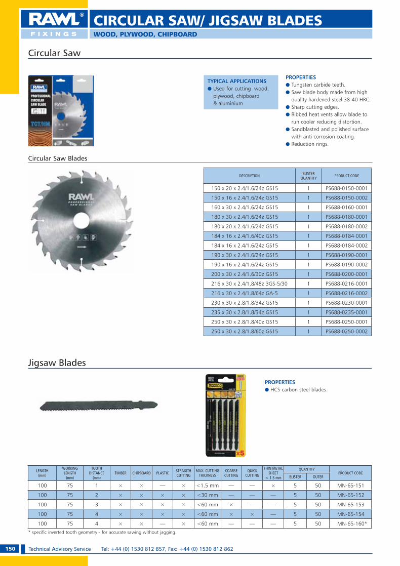
150 Technical Advisory Service Tel: +44 (0) 1530 812 857, Fax: +44 (0) 1530 812 862
WOOD, PLYWOOD, CHIPBOARD
CIRCULAR SAW/ JIGSAW BLADES
PROPERTIESe Tungsten carbide teeth.e Saw blade body made from high
quality hardened steel 38-40 HRC.e Sharp cutting edges.e Ribbed heat vents allow blade to
run cooler reducing distortion.e Sandblasted and polished surface
with anti corrosion coating.e Reduction rings.
DESCRIPTION BLISTER QUANTITY PRODUCT CODE
150 x 20 x 2.4/1.6/24z GS15 1 PS688-0150-0001
150 x 16 x 2.4/1.6/24z GS15 1 PS688-0150-0002
160 x 30 x 2.4/1.6/24z GS15 1 PS688-0160-0001
180 x 30 x 2.4/1.6/24z GS15 1 PS688-0180-0001
180 x 20 x 2.4/1.6/24z GS15 1 PS688-0180-0002
184 x 16 x 2.4/1.6/40z GS15 1 PS688-0184-0001
184 x 16 x 2.4/1.6/24z GS15 1 PS688-0184-0002
190 x 30 x 2.4/1.6/24z GS15 1 PS688-0190-0001
190 x 16 x 2.4/1.6/24z GS15 1 PS688-0190-0002
200 x 30 x 2.4/1.6/30z GS15 1 PS688-0200-0001
216 x 30 x 2.4/1.8/48z 3GS-5/30 1 PS688-0216-0001
216 x 30 x 2.4/1.8/64z GA-5 1 PS688-0216-0002
230 x 30 x 2.8/1.8/34z GS15 1 PS688-0230-0001
235 x 30 x 2.8/1.8/34z GS15 1 PS688-0235-0001
250 x 30 x 2.8/1.8/40z GS15 1 PS688-0250-0001
250 x 30 x 2.8/1.8/60z GS15 1 PS688-0250-0002
Circular Saw
TYPICAL APPLICATIONSe Used for cutting wood,
plywood, chipboard & aluminium
Circular Saw Blades
LENGTH(mm)
WORKING LENGTH
(mm)
TOOTH DISTANCE
(mm)TIMBER CHIPBOARD PLASTIC STRAIGTH
CUTTINGMAX. CUTTING
THICKNESSCOARSE CUTTING
QUICK CUTTING
THIN METAL SHEET
< 1.5 mm
QUANTITYPRODUCT CODE
BLISTER OUTER
100 75 1 × × — × <1.5 mm — — × 5 50 MN-65-151
100 75 2 × × × × <30 mm — — — 5 50 MN-65-152
100 75 3 × × × × <60 mm × — — 5 50 MN-65-153
100 75 4 × × × × <60 mm × × — 5 50 MN-65-154
100 75 4 × × — × <60 mm — — — 5 50 MN-65-160*
* specific inverted tooth geometry - for accurate sawing without jagging.
Jigsaw Blades
PROPERTIESe HCS carbon steel blades.
RAWL_KATALOG_2007_2008.indb 150RAWL_KATALOG_2007_2008.indb 150 2007-10-15 14:57:522007-10-15 14:57:52

151Technical Advisory Service e-mail: [email protected] OR [email protected]
NOTES
RAWL_KATALOG_2007_2008.indb 151RAWL_KATALOG_2007_2008.indb 151 2007-10-15 14:58:112007-10-15 14:58:11

152 Technical Advisory Service Tel: +44 (0) 1530 812 857, Fax: +44 (0) 1530 812 862
NOTES
RAWL_KATALOG_2007_2008.indb 152RAWL_KATALOG_2007_2008.indb 152 2007-10-15 14:58:112007-10-15 14:58:11

2 Technical Advisory Service Tel: +44 (0) 1530 812 857, Fax: +44 (0) 1530 812 862
The Technical Department off ers a variety of services to specifi ers, distributors and users of Rawl Fixings products.
Technical AdviceFixing specialists will off er immediate advice and
recommendations over the telephone.
Field EngineersAre available to off er fi xing advice at your offi ce
or on site.
Site TestingRawl Fixings engineers will conduct site testing to ensure the appropriate fi xing is specifi ed and used. A detailed report is provided with recom-mendations.
Technical (CPD) SeminarsWe will be pleased to provide technical seminars, to ensure personnel involved in the specifi cation and selection of structural anchors are up-to-date with developments and standards.
Contractor TrainingRawl Fixings engineers will be pleased to carry out practical training for contractors to ensure anchors are installed correctly.
Technical Calculation Software An innovative calculation CD ROM from Rawl
Fixings. Allows calculations and product selections
to be made in concrete. Includes both mechanical and chemical anchor
solutions. For your free CD, please e-mail Rawl Fixings
To ensure that we continue to meet the future requirements of the industry,
Rawlplug has a policy of continuous product development supported by
extensive design and test centre facilities. Rawlplug therefore reserves the
right to modify product designs without prior notice. Rawlplug also reserves
the right to modify information contained within this guide without notify-
ing existing holders of the document. While this document gives guidance
relating to the use and nature of the products and variety of applications, the
ultimate responsibility for correct selection of a product for a specifi c appli-
cation must lie with the customer. Rawlplug recommendations are made in
good faith but do not constitute a guarantee.
OKLADKA.indd 2OKLADKA.indd 2 2007-10-16 11:25:452007-10-16 11:25:45

Product Catalogue
RA
WL
FIX
ING
SP
rod
uct C
ata
log
ue
Octo
be
r 20
07
Rawlplug LtdSkibo Drive
Thornliebank Industrial Estate
Glasgow G46 8JR, UK
Sales Tel: +44 (0) 141 638 2255
Sales Fax: +44 (0) 141 273 2333
Export Sales Fax: +44 (0) 141 273 2336
Technical Tel: +44 (0) 1530 812857
Technical Fax: +44 (0) 1530 812862
Email: [email protected] or [email protected]
Rawlplug Ireland LtdUnit 14, Park West Industrial
Dublin 12, Ireland
Tel: +353 (0) 1 629 8479
Fax: +353 (0) 1 623 7053
Rawl France SarlZI Mitry-Compans
BP 536
12-14 Rue Marc Seguin
77295 Mitry-Mory cedex, France
Tel: +33 1 60 21 50 20
Fax: +33 1 64 67 19 84
e-mail: [email protected]
Rawl Scandinavia ABLysingsvägen 18
593 53 Västervik, Sweden
Tel: +46 (0) 490 30660
Fax: +46 (0) 490 30670
Koelner-Rawlplug Middle East FZEP.O. Box 261024
Jebel Ali Free Zone
Dubai
United Arab Emirates
Tel: + 971 4 8839501
Fax: + 971 4 8839502
e-mail: [email protected]
Website: www.rawlplug.com
® Rawl and Rawlplug are registered trade marks of RAWLPLUG Ltd.
Cl/SfB Xt6
October 2007
OKLADKA.indd 1OKLADKA.indd 1 2007-10-16 11:25:362007-10-16 11:25:36