Complete Coverage Littoral Zone & BackbeachSurvey at Cedar ...
16
Complete Coverage Littoral Zone & Backbeach Survey at Cedar Bayou by Combining Structure from Motion Photogrammetry, RTK GPS Topography, and Single Beam Hydrography 2016 Texas Chapter ASBPA Symposium
Transcript of Complete Coverage Littoral Zone & BackbeachSurvey at Cedar ...

Complete Coverage Littoral Zone & Backbeach Survey at Cedar Bayou by
Combining Structure from Motion Photogrammetry, RTK GPS Topography,
and Single Beam Hydrography
2016 Texas Chapter ASBPA Symposium

Goals/Motivation:• Complete topographic & hydrographic coverage for project site
• Approach lidar coverage & accuracy
• Incorporate Structure from Motion (SfM) + GPS topography + single beam sonar
• Assess accuracies of SfM topographic coverage• Decide on where to delineate then combine datasets

SfM Photogrammetry• Implemented with many drone software packages• Non-metric camera• Based on image-matching algorithms (SIFT)
• Independent of scale (altitude variance) and orientation• can match images with varying contrasts/exposure• Matches higher order patterns within raster, not cell by cell
• Triangulation of individual pixels using matched pairs1. Bundle block adjustment-interior/exterior orientation2. multiview stereo dense matching-point cloud densification
• DEM (derived from point cloud)• Orthomosaic derived from DEM

Multiview Matchpointsat Cedar Bayou

Site: Cedar Bayou• Historically open channel
• Re-opened in 2014 by Aransas County
• ~ 10.4 km2 (2,500 acres)• 14,000 ft Gulf Beach • 16,000 ft of improved
channels within survey area• Challenges include collecting
topography through sloughs, over mud flats, over dunes
Cedar Bayou (10/2015)

Cedar Bayou – Survey Setup
• More than 10 ground control points (GCPs) used to ensure accurate horizontal and vertical control
• Flight plan: 85% frontal overlap and 70% sidelap to aid in image matching where images have homogenous visual content (i.e. sand flats, water, vegetation). High overlap provides more redundancy for higher accuracy
• Hydro transects setup to capture channel lines and profile trends

Data collection:
• Aerial targets incorporated via RTK survey
• Rover RTK observations tied to monument with static GPS observations
• GCPs given weight based on accuracy and used to adjust SfM model
GCPs – Baseline for accuracy• UAS (drones) have
maximum legal height of 400 ft for ground sample distance of ~2.2cm (18mp cam, 24mm focal length)
• Cedar Bayou ortho would be unmanageable at 25 X 109
pixels• Greater altitude = more
area, manageable files

SfM points of failure• Check model against topo/bathy data
1. point/DSM comparison2. Visual cross-sectional profiles
• Cedar Bayou has areas of very shallow water that can be modeled with SfM pipeline
• Inherently noisy• wavelets/glint/surface interference causes false matches
• Most modeling with water coverage must be removed• RTK GPS topography & hydrographic bathymetry necessary
to achieve complete coverage• Caution with areas of high vegetation


SfM error analysis• GPS observation vs. SfM DEM • Average vertical error for all terrestrial
topography was 0.33ft (10cm)• RMSE was 0.78ft (• Includes error as a result of vegetative
coverage/wave run-up


Composite topo-bathymetric DEM
• Breaks where SfM model failed were assessed using cross-sectional profiles and digitized using vector data
• Composite DEM created using TIN and raster formats
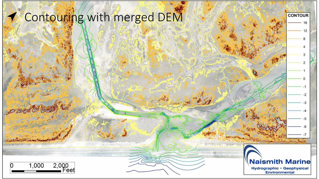
Contouring with merged DEM

Discussion:• SfM pipeline enables low-cost, high resolution topographic coverage
for large areas• On-the-ground survey integral part of SfM modeling
1. Tie & weight SfM tie points to control network2. Ground truth and clipping polygons (cross-section profiles)3. Bathymetry where SfM tie points fail
• High altitude necessary for large areas at expense of accuracy

Cedar Bayou SfM DEM tour