Compatibility Testing of Salton Sea Geothermal Brines · Compatibility Testing of Salton Sea...
10
Proceedings World Geothermal Congress 2015 Melbourne, Australia, 19-25 April 2015 1 Compatibility Testing of Salton Sea Geothermal Brines John Featherstone, Darrell Gallup, Stephen Harrison, Dennis Jenkins, Paul von Hirtz Thermochem, Inc., 3414 Regional Parkway, Santa Rosa, CA 95403 [email protected] Keywords: scaling, corrosion, production chemistry, brines, mineral recovery ABSTRACT Simbol Materials plans to install a commercial facility to recover lithium from brine supplied by Salton Sea geothermal power plants. Simbol intends to ultimately process 100% of the pre-injection brine, obtained downstream of the EnergySource Hudson Ranch clarifiers at the head tank, and return it to the same injection brine line as used by the power plant, where it is then pumped to the reinjection wells. There is a concern that mixing of the lithium-depleted SIMBOL treated and the pre-injection brine may produce corrosive and scaling-forming brine. It is important that the Simbol depleted brine does not reduce the injectivity of the injection wells. When pre-injection brine is mixed with Simbol depleted brine there should be no incompatibility between the two brines in terms of injectivity and the mixture should be at least as injectable as the unprocessed brine currently being injected. A testing program was developed to confirm that mixtures of pre-injection brine and Simbol depleted brine are chemically compatible, and can achieve equal or better simulated injectivity than the current injection brine. In order to access the brine compatibility and relative injectivity, a Thermochem, Inc. (TCI) Hold-up Vessel and Packed-bed (HUV-PB) test skid was used. This unit is utilized to examine brine incompatibility and relative injectivity in a flow-through system, where the two brine streams are combined in various ratios (from 0 to 100% each), aged for a time interval equivalent to the residence time in the power plant injection system, and pumped through a packed bed of drill cuttings (rock chips) from the geothermal injection wells for the plant. Testing was performed on 100% Hudson Ranch brine, 100% Simbol brine and a 50:50% mixture of the two brines. The drill cuttings used were chosen to be representative of the main permeable zones in the injection wells. Incompatibility is primarily manifested as a shorter run time to reach a 1000 maximum psid, due to generation of suspended solids and scales that cause an increase in pressure across the packed bed. The packed beds were weighed and the bulk porosity measured before and after each test to determine the mass of deposits from the brine and changes of porosity in the packed bed matrix. The packing was also examined by SEM and XRD to evaluate the nature of deposited materials within the beds. The 100% Simbol depleted brine causes dramatically less permeability and porosity loss for the packed beds and results in a much lower deposition rate of solids within the beds compared to 100% pre-injection brine and the 50:50 mixture of the two. The Simbol depleted brine performs better by 1 to 2 orders of magnitude for these parameters over the pre-injection brine and 50:50 mixture. Other than the precipitation of salts, which can be managed by simple temperature and brine dilution control processes, there were no measureable compatibility issues with the 50:50 blend in terms of injectivity. 1. INTRODUCTION Simbol’s initial commercial facility (CP1) will process Salton Sea geothermal brine, obtained downstream of the clarifiers at the head tank, and return it to the same injection brine line as used by the power plant, where it is then pumped to the reinjection wells. The Simbol process will extract essentially all the remaining iron, silica, lithium, and eventually manganese and zinc from the feed brine. The proportion of the clarified brine that Simbol will take is expected to be in the range of 50% to 100% of the power plant total brine flow. The brine returned from the Simbol CP1 facility, termed Simbol depleted brine, will be mixed with any remaining pre-injection (PI) brine not treated by CP1, and pumped into the reinjection wells. The injection system, pipelines and wells, are sensitive to the deposition of solids which can increase pressure drop and decrease injectivity. Loss of injectivity in wells requires increased pumping pressure to compensate, increasing parasitic loads up to the point where injection may no longer be feasible, at which point a work-over or re-drill is required. Therefore scale-forming reactions and the presence of suspended solids must be minimized. The power plant actively manages the quality of the reinjection brine through crystallizer-clarifier processes and chemical scale inhibition and requires that the Simbol depleted brine returned for reinjection is of equal or better quality in terms of injectivity. The Simbol brine treatment process is a trade secret and cannot be disclosed here. It removes silica, iron, arsenic, barite and calcite from the brine and then lithium chloride is extracted selectively. The Li-depleted brine is sent back to the power plant for reinjection to the reservoir. The major chemical differences between the PI brine and depleted brine are the almost total removal of Fe, Si, and As, plus the significant reduction in Ba, SO 4 , F, and Pb concentrations. There is also an increase in pH, oxygen concentration, and ORP (oxidation-reduction potential) in the depleted brine relative to PI brine. Since the PI brine and the Simbol depleted brine will have different chemical makeup, there is a risk that the PI brine and depleted brine mixtures will develop suspended solids or precipitate scale, and potentially affect the surface scaling rates and brine injectivity of the injection wells. Four potential risks have been identified related to mixing of these brines as listed below.
-
Upload
phunghuong -
Category
Documents
-
view
223 -
download
0
Transcript of Compatibility Testing of Salton Sea Geothermal Brines · Compatibility Testing of Salton Sea...
Proceedings World Geothermal Congress 2015
Melbourne, Australia, 19-25 April 2015
1
Compatibility Testing of Salton Sea Geothermal Brines
John Featherstone, Darrell Gallup, Stephen Harrison, Dennis Jenkins, Paul von Hirtz
Thermochem, Inc., 3414 Regional Parkway, Santa Rosa, CA 95403
Keywords: scaling, corrosion, production chemistry, brines, mineral recovery
ABSTRACT
Simbol Materials plans to install a commercial facility to recover lithium from brine supplied by Salton Sea geothermal power
plants. Simbol intends to ultimately process 100% of the pre-injection brine, obtained downstream of the EnergySource Hudson
Ranch clarifiers at the head tank, and return it to the same injection brine line as used by the power plant, where it is then pumped
to the reinjection wells. There is a concern that mixing of the lithium-depleted SIMBOL treated and the pre-injection brine may
produce corrosive and scaling-forming brine.
It is important that the Simbol depleted brine does not reduce the injectivity of the injection wells. When pre-injection brine is
mixed with Simbol depleted brine there should be no incompatibility between the two brines in terms of injectivity and the mixture
should be at least as injectable as the unprocessed brine currently being injected.
A testing program was developed to confirm that mixtures of pre-injection brine and Simbol depleted brine are chemically
compatible, and can achieve equal or better simulated injectivity than the current injection brine. In order to access the brine
compatibility and relative injectivity, a Thermochem, Inc. (TCI) Hold-up Vessel and Packed-bed (HUV-PB) test skid was used.
This unit is utilized to examine brine incompatibility and relative injectivity in a flow-through system, where the two brine streams
are combined in various ratios (from 0 to 100% each), aged for a time interval equivalent to the residence time in the power plant
injection system, and pumped through a packed bed of drill cuttings (rock chips) from the geothermal injection wells for the plant.
Testing was performed on 100% Hudson Ranch brine, 100% Simbol brine and a 50:50% mixture of the two brines. The drill
cuttings used were chosen to be representative of the main permeable zones in the injection wells. Incompatibility is primarily
manifested as a shorter run time to reach a 1000 maximum psid, due to generation of suspended solids and scales that cause an
increase in pressure across the packed bed. The packed beds were weighed and the bulk porosity measured before and after each
test to determine the mass of deposits from the brine and changes of porosity in the packed bed matrix. The packing was also
examined by SEM and XRD to evaluate the nature of deposited materials within the beds.
The 100% Simbol depleted brine causes dramatically less permeability and porosity loss for the packed beds and results in a much
lower deposition rate of solids within the beds compared to 100% pre-injection brine and the 50:50 mixture of the two. The Simbol
depleted brine performs better by 1 to 2 orders of magnitude for these parameters over the pre-injection brine and 50:50 mixture.
Other than the precipitation of salts, which can be managed by simple temperature and brine dilution control processes, there were
no measureable compatibility issues with the 50:50 blend in terms of injectivity.
1. INTRODUCTION
Simbol’s initial commercial facility (CP1) will process Salton Sea geothermal brine, obtained downstream of the clarifiers at the
head tank, and return it to the same injection brine line as used by the power plant, where it is then pumped to the reinjection wells.
The Simbol process will extract essentially all the remaining iron, silica, lithium, and eventually manganese and zinc from the feed
brine. The proportion of the clarified brine that Simbol will take is expected to be in the range of 50% to 100% of the power plant
total brine flow. The brine returned from the Simbol CP1 facility, termed Simbol depleted brine, will be mixed with any remaining
pre-injection (PI) brine not treated by CP1, and pumped into the reinjection wells. The injection system, pipelines and wells, are
sensitive to the deposition of solids which can increase pressure drop and decrease injectivity. Loss of injectivity in wells requires
increased pumping pressure to compensate, increasing parasitic loads up to the point where injection may no longer be feasible, at
which point a work-over or re-drill is required. Therefore scale-forming reactions and the presence of suspended solids must be
minimized. The power plant actively manages the quality of the reinjection brine through crystallizer-clarifier processes and
chemical scale inhibition and requires that the Simbol depleted brine returned for reinjection is of equal or better quality in terms of
injectivity.
The Simbol brine treatment process is a trade secret and cannot be disclosed here. It removes silica, iron, arsenic, barite and calcite
from the brine and then lithium chloride is extracted selectively. The Li-depleted brine is sent back to the power plant for
reinjection to the reservoir.
The major chemical differences between the PI brine and depleted brine are the almost total removal of Fe, Si, and As, plus the
significant reduction in Ba, SO4, F, and Pb concentrations. There is also an increase in pH, oxygen concentration, and ORP
(oxidation-reduction potential) in the depleted brine relative to PI brine.
Since the PI brine and the Simbol depleted brine will have different chemical makeup, there is a risk that the PI brine and depleted
brine mixtures will develop suspended solids or precipitate scale, and potentially affect the surface scaling rates and brine
injectivity of the injection wells. Four potential risks have been identified related to mixing of these brines as listed below.

Featherstone et al.
2
1. The depleted brine contains TSS above that of the PI brine, reducing well injectivity.
2. The depleted brine contains dissolved oxygen that causes oxidation of Fe+2 upon mixing with PI brine. Ferric iron can
form hydroxide sols or can react with silica to form hydrous ferric silicate scale and could adversely impact the surface
piping, well casings and injection formation.
3. Barium sulfate (BaSO4), calcium fluoride (CaF), sodium chloride (NaCl) and/or other salts precipitate upon mixing
because the depleted brine is colder than the feed brine and saturation point is exceeded for these salts at the mixture
temperature. This potential deposition could also impact the surface piping, well casings and injection formation.
4. The depleted brine, alone or mixed with PI brine, initiates other reactions which increase scaling and fouling of injection
wells beyond that occurring for PI brine currently.
It should be noted that most of the above risks, if any are manifested, could be mitigated through process control and/or additional
chemical treatment. For example, chemical incompatibility and precipitation could be relieved by adding an oxygen scavenger/ Fe+3
reducing agent and adjusting the pH to prevent Fe+3 hydroxides/oxides, reject brine temperatures adjusted, dilution water rates
increased and chemical scale inhibitors added.
Simbol initially conducted a bench top study to evaluate some of the risks above using a glass reactor vessel on-site at their
Demonstration Plant at the Salton Sea field. Batch tests under controlled conditions were conducted to detect any reactions that
may increase TSS upon mixing the two brine streams at various ratios. These reactor vessel tests showed that minimal
incompatibility arose from mixing the two brines in various volumetric ratios. The tests described in the present study were
conducted whereby a continuous flow test unit was used to provide a relative simulation of the brine mixing and reinjection process
in a reproducible manner. Simbol depleted and PI brines, mixed and unmixed, were pumped through a hold-up vessel to simulate
the injection system residence time, and a packed-bed of drill cuttings to simulate the injection well reservoir formation.
2. TEST OBJECTIVES
The objective of the present testing program was to confirm that mixtures of PI brine and Simbol depleted brine are chemically
compatible, or can be managed to achieve equal or better simulated injectivity than the current PI brine. This involved pumping the
PI brine and Simbol depleted brine through a Thermochem Hold-up Vessel / Packed-bed (HUV-PB) test skid. The skid was
designed to simulate injection brine conditions at the field with respect to temperature, retention time in brine injection lines and
wells, and interactions of brines with reservoir rocks in the injection wells.
Compatibility was evaluated by comparing relative rates of permeability loss through the packed beds under controlled and
reproducible conditions, mass deposition rates of solids in the beds, amount of bulk porosity loss from the bed matrix, the nature of
deposited solids, and relative changes in fluid chemistry through the process. The most immediate and obvious result obtained in
these tests is the permeability change over time. Since permeability is inversely proportional to pressure drop (DP) through the bed
at constant flow, these results are usually expressed simply as DP versus time.
3. TEST METHODOLOGY
The experiments were performed at Simbol’s Demonstration Pilot facility adjacent to the Hudson Ranch geothermal power plant.
The testing equipment is designed to approximately simulate the residence time during reinjection and chemical environment of the
injection formation. The unit is not intended to duplicate the injection well formation conditions, but provide a relative and
reproducible test that can be related to injection well formation conditions.
The fouling rate (DP) was monitored real-time at constant flow through the beds. The packing configuration and flow through the
bed are designed to provide accelerated fouling compared to that occurring in the injection well. Although the packing permeability
is much greater than the average injection zone permeability, the interstitial fluid velocity is much higher, resulting in an
accelerated TSS deposition and rate of chemical precipitation. The packed beds were constructed from 1-inch diameter titanium
tubes and packed with screened drilling chips from the actual injection wells used by PI. The cuttings were screened to a size range
between 1 and 2 mm. The uniform packing material allows preparation of beds with almost identical characteristics, so test
conditions are reproducible. The rock chips primarily consisted of hydrothermally-crystallized, fine-grained, granitic material
composed of quartz and feldspar, and silica-bonded meta-siltstone.
A side-stream of the PI injection brine and Simbol depleted brine was supplied to the test skid through heat-traced Teflon PFA 0.5-
inch diameter tubing at about 10 psig from continuously flowing bypass loops. The brine streams are metered by positive-
displacement peristaltic pumps on the skid at a controlled ratio through a hold-up vessel (HVU) to simulate the 30 minute average
residence time in the injection pipeline and well casings. The HUV is fitted with baffles and mixing paddles to provide plug flow
without settling of suspended solids. The brine is then pumped under high-pressure (up to 1000 psig) through the packed beds in
order to simulate the reservoir formation.
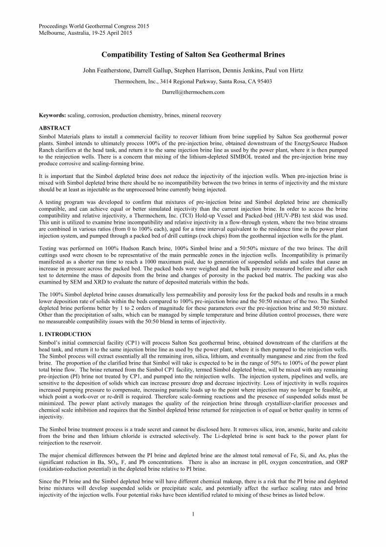
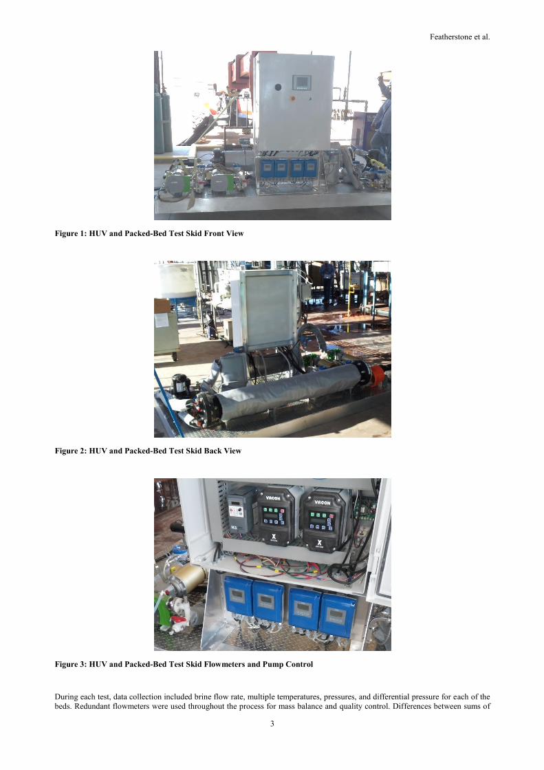
Photos of the skid as installed at the Simbol Demonstration Plant are shown in Figures 1 - 3. Due to the corrosive nature of the PI
and Simbol brine streams, a variety of corrosion-resistant materials are used. Austenitic stainless steel is avoided as much as
possible given stress-corrosion cracking potential, but had to be used for some components due to availability and cost of
alternatives. The brine feed mixing pumps have Kynar (PVDF) flanges and EPDM hoses. The high-pressure (HP) packed bed pump
head is Hastelloy C-276 with Viton diaphragms. The magnetic flowmeters are Teflon PFA-lined with Hastelloy electrodes and
Kynar flanges. The Hold-up vessel is fabricated from fiberglass with Inconel 625 baffles and drive rod, Teflon TFE mixing
elements, and Kynar low-pressure relief valve. All tubing used to transport fluids is duplex 2205 stainless steel (SS) in order to
simulate the PI injection pipeline. Teflon-lined hose with 316 SS over-braid and end connectors is used to connect pressure
transmitters to the process flow line and thermocouples are inserted directly into the process tubing through Teflon TFE packing’s.
The valves inter-connecting the feed pump inlets are Hastelloy C-276. The HUV and fluid tubing were insulated and heat-traced to
maintain process temperatures and minimize the potential for bulk salt precipitation.
Featherstone et al.
3
Figure 1: HUV and Packed-Bed Test Skid Front View
Figure 2: HUV and Packed-Bed Test Skid Back View
Figure 3: HUV and Packed-Bed Test Skid Flowmeters and Pump Control
During each test, data collection included brine flow rate, multiple temperatures, pressures, and differential pressure for each of the
beds. Redundant flowmeters were used throughout the process for mass balance and quality control. Differences between sums of
Featherstone et al.
4
redundant meters at different ends of the process (mass balance) were on the order of 0.5 to 3%. Redundant pressure sensors for the
packed bed agreed within a few psi or less.
Brine samples were collected during each test for chemical analysis upstream and downstream of the HUV. The tests were run until
the pressure drop (DP) across the packed bed indicated significant plugging (approaching 1000 psid) while the brine flowrate
through the column is maintained at a constant rate by a positive displacement pump. For the 100% Simbol depleted brine, the time
projected to reach a 1000 psid DP was over 1000 hours, so these tests were terminated after about 300 to 350 hours (about 2
weeks).
At the end of each test the packed beds were weighed to determine the amount of scale deposited and the residual bulk porosity of
the packed bed was measured. Cross-sections of the packed bed were examined by Scanning Electron Microscopy (SEM) and X-
ray diffraction (XRD). Brine samples were analyzed by the Simbol laboratory for chemical composition, major and trace metals,
and some for major anions.
4. HOLD-UP VESSEL AND PACKED-BED DESIGN CONCEPT
TCI has built and installed several of these units at geothermal fields around the world. A HUV-PB unit was used in the Imperial
Valley at East Mesa, but the Simbol unit is the first to be used in the Salton Sea. The HUV-PB test is a procedure routinely
employed by TCI at geothermal power projects to measure relative injectivity impacts of different operating and treatment
conditions for geothermal fluids, to detect accelerated injectivity loss, and to provide an early warning of process problems that
may contribute to such loss. The HUV-PB unit is most often used to evaluate relative differences in silica scaling impacts to the
formation for various bottoming cycle options in conventional geothermal fields where dual-flash and hybrid-binary cycles are
being considered with treatment options such as pH-modification and inhibitors. Since the HUV is a stirred plug-flow reactor
design, it maintains suspended solids in solution and prevents premature settling and deposition upstream of the packed-bed.
Formation fouling can be the result of both plugging from suspended solids and mineral scale deposition. Suspended particles of
silica and iron can also have a major effect on silica deposition. The plug-flow design ensures the average residence time is within
the range of the actual process (no early breakthrough and minimal hold-up). The baffled, plug-flow design with stirred sections
keeps solid particles suspended in solution.
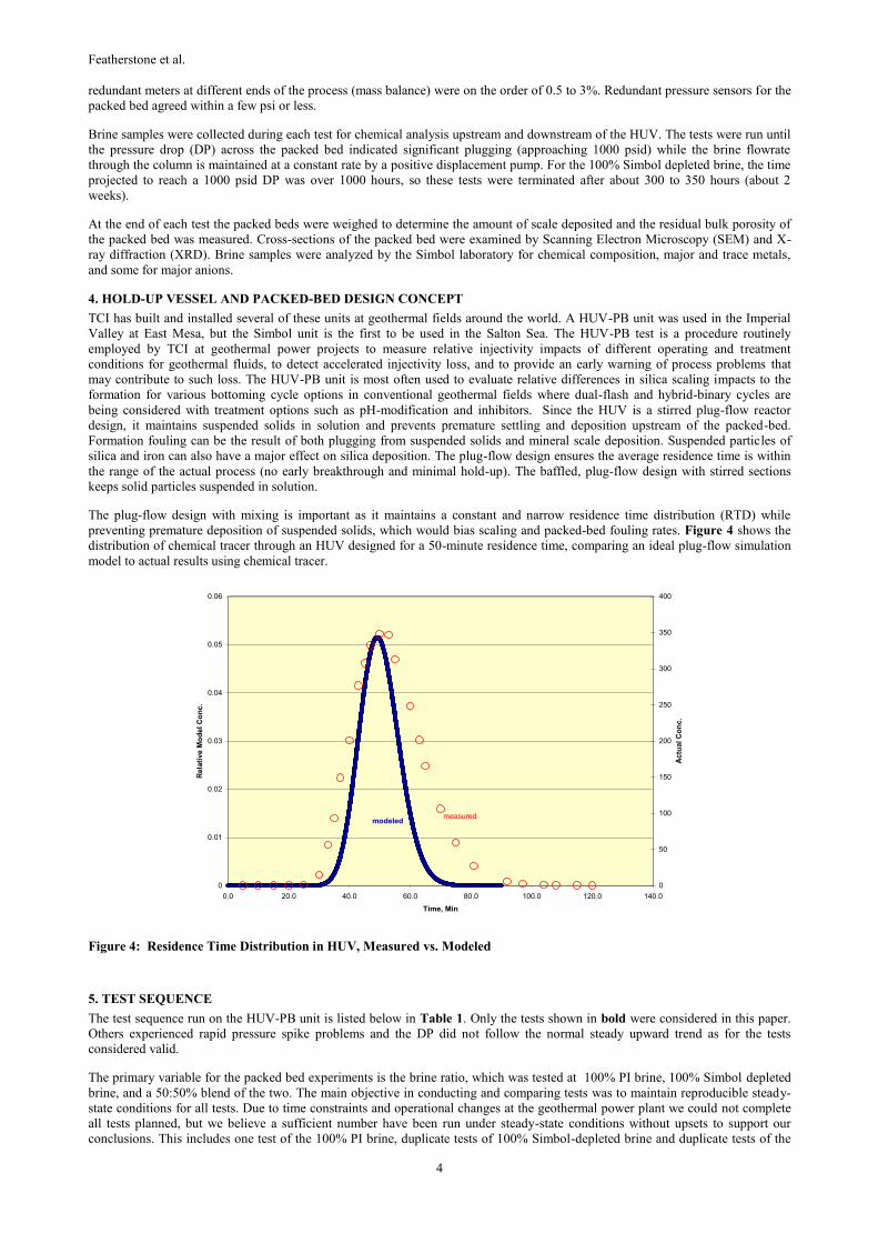
The plug-flow design with mixing is important as it maintains a constant and narrow residence time distribution (RTD) while
preventing premature deposition of suspended solids, which would bias scaling and packed-bed fouling rates. Figure 4 shows the
distribution of chemical tracer through an HUV designed for a 50-minute residence time, comparing an ideal plug-flow simulation
model to actual results using chemical tracer.
Figure 4: Residence Time Distribution in HUV, Measured vs. Modeled
5. TEST SEQUENCE
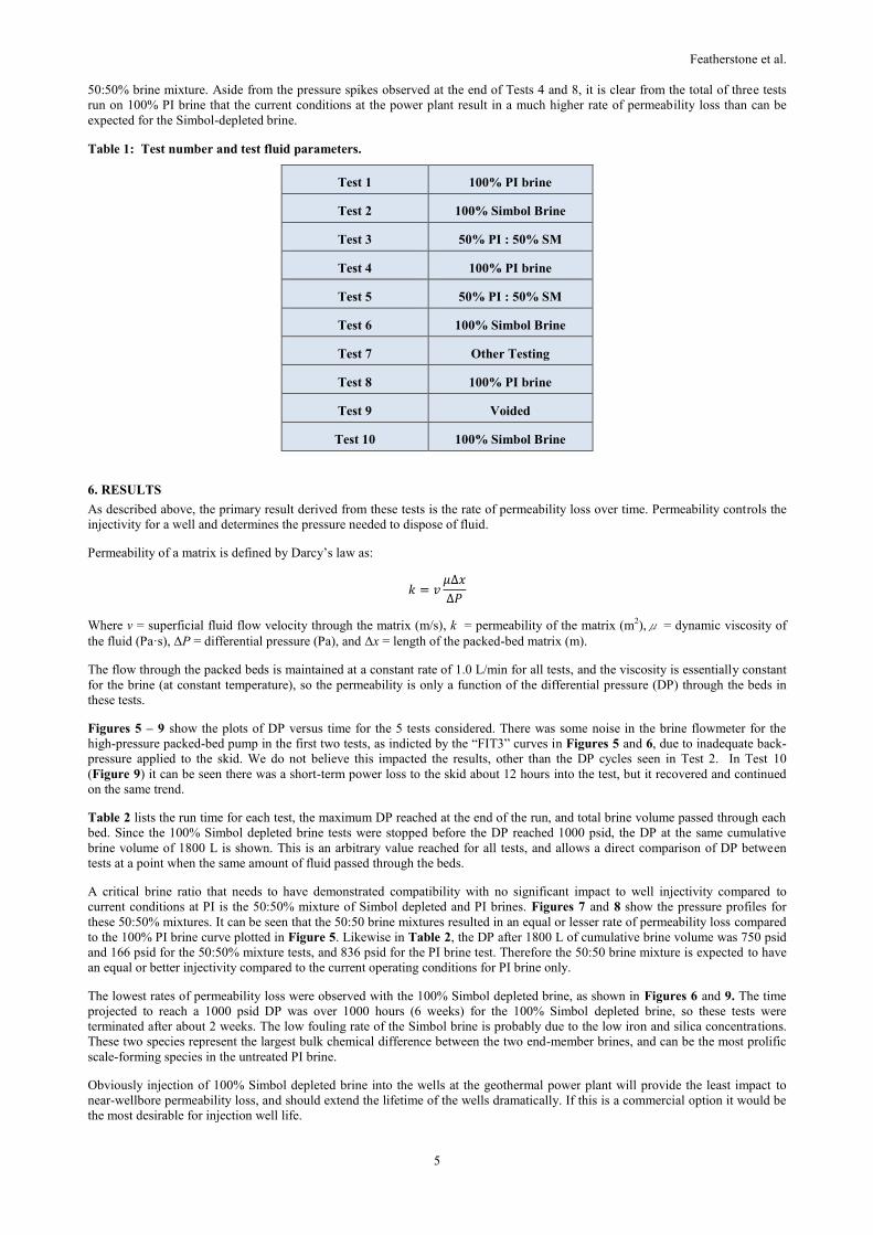
The test sequence run on the HUV-PB unit is listed below in Table 1. Only the tests shown in bold were considered in this paper.
Others experienced rapid pressure spike problems and the DP did not follow the normal steady upward trend as for the tests
considered valid.
The primary variable for the packed bed experiments is the brine ratio, which was tested at 100% PI brine, 100% Simbol depleted
brine, and a 50:50% blend of the two. The main objective in conducting and comparing tests was to maintain reproducible steady-
state conditions for all tests. Due to time constraints and operational changes at the geothermal power plant we could not complete
all tests planned, but we believe a sufficient number have been run under steady-state conditions without upsets to support our
conclusions. This includes one test of the 100% PI brine, duplicate tests of 100% Simbol-depleted brine and duplicate tests of the
0
0.01
0.02
0.03
0.04
0.05
0.06
0.0 20.0 40.0 60.0 80.0 100.0 120.0 140.0
Time, Min
Rela
tive M
od
el
Co
nc.
0
50
100
150
200
250
300
350
400
Actu
al
Co
nc.
modeledmeasured
Featherstone et al.
5
50:50% brine mixture. Aside from the pressure spikes observed at the end of Tests 4 and 8, it is clear from the total of three tests
run on 100% PI brine that the current conditions at the power plant result in a much higher rate of permeability loss than can be
expected for the Simbol-depleted brine.
Table 1: Test number and test fluid parameters.
Test 1 100% PI brine
Test 2 100% Simbol Brine
Test 3 50% PI : 50% SM
Test 4 100% PI brine
Test 5 50% PI : 50% SM
Test 6 100% Simbol Brine
Test 7 Other Testing
Test 8 100% PI brine
Test 9 Voided
Test 10 100% Simbol Brine
6. RESULTS
As described above, the primary result derived from these tests is the rate of permeability loss over time. Permeability controls the
injectivity for a well and determines the pressure needed to dispose of fluid.
Permeability of a matrix is defined by Darcy’s law as:
𝑘 = 𝑣𝜇∆𝑥
∆𝑃
Where v = superficial fluid flow velocity through the matrix (m/s), k = permeability of the matrix (m2),μ = dynamic viscosity of
the fluid (Pa·s), ΔP = differential pressure (Pa), and Δx = length of the packed-bed matrix (m).
The flow through the packed beds is maintained at a constant rate of 1.0 L/min for all tests, and the viscosity is essentially constant
for the brine (at constant temperature), so the permeability is only a function of the differential pressure (DP) through the beds in
these tests.
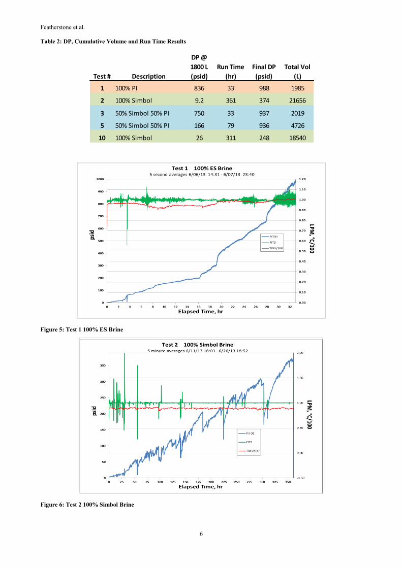
Figures 5 – 9 show the plots of DP versus time for the 5 tests considered. There was some noise in the brine flowmeter for the
high-pressure packed-bed pump in the first two tests, as indicted by the “FIT3” curves in Figures 5 and 6, due to inadequate back-
pressure applied to the skid. We do not believe this impacted the results, other than the DP cycles seen in Test 2. In Test 10
(Figure 9) it can be seen there was a short-term power loss to the skid about 12 hours into the test, but it recovered and continued
on the same trend.
Table 2 lists the run time for each test, the maximum DP reached at the end of the run, and total brine volume passed through each
bed. Since the 100% Simbol depleted brine tests were stopped before the DP reached 1000 psid, the DP at the same cumulative
brine volume of 1800 L is shown. This is an arbitrary value reached for all tests, and allows a direct comparison of DP between
tests at a point when the same amount of fluid passed through the beds.
A critical brine ratio that needs to have demonstrated compatibility with no significant impact to well injectivity compared to
current conditions at PI is the 50:50% mixture of Simbol depleted and PI brines. Figures 7 and 8 show the pressure profiles for
these 50:50% mixtures. It can be seen that the 50:50 brine mixtures resulted in an equal or lesser rate of permeability loss compared
to the 100% PI brine curve plotted in Figure 5. Likewise in Table 2, the DP after 1800 L of cumulative brine volume was 750 psid
and 166 psid for the 50:50% mixture tests, and 836 psid for the PI brine test. Therefore the 50:50 brine mixture is expected to have
an equal or better injectivity compared to the current operating conditions for PI brine only.
The lowest rates of permeability loss were observed with the 100% Simbol depleted brine, as shown in Figures 6 and 9. The time
projected to reach a 1000 psid DP was over 1000 hours (6 weeks) for the 100% Simbol depleted brine, so these tests were
terminated after about 2 weeks. The low fouling rate of the Simbol brine is probably due to the low iron and silica concentrations.
These two species represent the largest bulk chemical difference between the two end-member brines, and can be the most prolific
scale-forming species in the untreated PI brine.
Obviously injection of 100% Simbol depleted brine into the wells at the geothermal power plant will provide the least impact to
near-wellbore permeability loss, and should extend the lifetime of the wells dramatically. If this is a commercial option it would be
the most desirable for injection well life.
Featherstone et al.
6
Table 2: DP, Cumulative Volume and Run Time Results
Figure 5: Test 1 100% ES Brine
Figure 6: Test 2 100% Simbol Brine
Test # Description
DP @
1800 L
(psid)
Run Time
(hr)
Final DP
(psid)
Total Vol
(L)
1 100% PI 836 33 988 1985
2 100% Simbol 9.2 361 374 21656
3 50% Simbol 50% PI 750 33 937 2019
5 50% Simbol 50% PI 166 79 936 4726
10 100% Simbol 26 311 248 18540

Featherstone et al.
7
.
Figure 7: Test 3 50% Simbol 50% ES Brine
Figure 8. Test 5 50% Simbol 50% ES Brine
Figure 9: Test 10 100% Simbol Brine

Featherstone et al.
8
7. PACKED BED WEIGHTS AND POROSITY
The data showing the change in weight and bulk porosity for the packed beds from each test, the cumulative brine volume, and the
concentration of deposited solids relative to the brine volume is summarized in Table 3.
At the end of each test, the packed bed tubes were flushed with de-ionized water, capped, and sent to TCI to be dried and weighed
for porosity measurements, and cut open and for SEM and XRD analysis. The weight increase of the tubes is a direct measurement
of trapped TSS material and chemical precipitation in the packed bed matrix. It can be seen in Table 3 that the 100% Simbol brine
weight gains are essentially zero after about 20,000 L of brine passed through the matrix, suggesting that it deposits virtually no
scale (+/- 0.1 mg/L), while the PI brine value indicates a weight gain of 20 g for almost 2000 L of brine, or a deposition rate of 10
mg/L.
The 50:50 brine mixture shows a significantly higher weight gain, due to the presence of halite (NaCl) and iron chloride, as seen in
the SEM and XRD analysis results. Halite precipitation is likely a result of the lower temperature of the Simbol brine mixing with
the higher temperature PI brine, resulting in a mixture that exceeds the saturation index for halite (and some iron chloride salts).
The change in packed bed porosity as shown in Table 3 is consistent with the weight gains as expected. The 100% Simbol brine
results in almost no porosity change, while the 100% PI and 50:50 brine mixtures show losses in porosity of 11 to 18%,
respectively. The pores are being plugged with suspended solids and chemical precipitates. But the nature of the deposits within the
beds, and how effectively they occlude flowpaths through the matrix, will impact the rate of permeability loss. Weight gains and
bulk porosity loss are not necessarily proportional to permeability loss, as evidenced in comparing the tests of PI and 50:50 brine
mixtures.
Table 3: Porosity and Weight Gain Results
8. CHEMICAL TEST RESULTS
Brine samples and all of the packed-bed solids were analyzed. The data (not shown) was only used on a relative basis to determine
if chemical changes occurred through the test process. The precision of the data appeared to be sufficient to conclude that no
significant chemical changes, reactions or deposition, occurred upon mixing and after passing through the HUV, other than that
observed in the packed-beds themselves. This conclusion is consistent with the observation that no significant deposition or
accumulation of solids was found in the HUV between tests when it was opened for inspection. In fact the vessel was remarkably
clean, aside from some minor salt accumulation, as shown below in Figure 10. The SEM/EDX/XRD analyses of the solids in the
packed beds (not shown) were also consistent with chemical mechanisms of scaling expected from these brines.
Figure 10: HUV Internal Baffle Outlet after Test 7
Test # Description
Initial
Porosity
(%)
Weight
gain (g)
Final
Porosity
(%)
Porosity
Change
(%)
Total Vol
(L)
Solids
Rate
(mg/L)
1 100% PI 28.6 19.1 18.0 -10.7 1985 10
2 100% Simbol 27.7 3.15 28.3 0.6 21656 0.1
3 50% Simbol 50% PI 27.1 64.6 10.0 -17.1 2019 32
5 50% Simbol 50% PI 25.6 74.8 7.9 -17.7 4726 16
10 100% Simbol 25.5 -2.56 30.0 4.5 18540 -0.1

Featherstone et al.
9
9. COMPARATIVE RESULTS
Overall the HUV-PB test skid ran smoothly with few interruptions during the testing program. The primary results of the tests are
summarized in Figures 11 and 12, which plots differential pressure (DP) across the packed bed vs. time. Since the brine flowrate is
maintained at a constant rate over these tests, these curves represent relative changes in injectivity or permeability. The injectivity
of a well is expressed in terms of flowrate/pressure, so with increasing DP at constant flow the relative injectivity is decreasing.
Permeability is also linear with DP, so these curves are inversely proportional to permeability loss. Some of the tests shown in
Figure 11 were not entirely under steady-state process conditions, resulting in rapid pressure spikes near the end of these tests as
mentioned above. Figure 12 includes only tests that finished under steady-state conditions with no process upsets. Even the limited
data set in Figure 12 clearly shows that the 100% Simbol brine results in a much lower rate of injectivity decline compared to the
PI brine, and combined 50:50 brine mixture results in the same or lower injectivity loss over time as the PI brine.
Figure 11: Summary of Run Time vs. Pressure - all Tests
Figure 12: Summary of Run Time vs. Pressure - Selected Tests
In order to determine if any significant chemical reactions were taking place through the simulated injection system (HUV) as a
result of mixing and aging the fluid, samples were collected and analyzed. No significant change in brine chemistry was observed
for these samples, collected before and after the HUV, and the results were within normal analytical variation. Therefore the 50:50
Featherstone et al.
10
brine mixture can be considered compatible in that precipitation reactions were not measureable by chemical mass balance, and the
aged 100% Simbol depleted brine was also stable through the process.
Likewise, the total suspended solids (TSS) measured in the Simbol depleted brine was lower than the PI brine, and the 50:50
mixture of brines had less than or equal TSS relative to the PI brine. With respect to precipitation of solids that form suspended
material in the brine, which can be a major factor in injection well scaling and plugging, the mixed brine at the 50:50 ratio can be
considered compatible and the 100% Simbol depleted brine is superior.
The 100% Simbol depleted brine packed beds had negligible changes in weight and porosity. The 100% PI brine and the 50:50
brine mixtures resulted in weight gains of 20 to 75 g, solids deposition rates of 10 to 32 mg/kg brine and relative losses in porosity
of 37 to 67%. The 50:50 brine mixtures actually resulted in higher weight gains and porosity losses than the 100% PI brine. The
high weight gain and porosity loss for the 50:50 brine mixtures is mostly likely due to bulk salt precipitation. The mixing of higher
temperature PI brine with the lower temperature Simbol brine apparently resulted in a mixture exceeding the solubility of NaCl and
iron-chloride salts. This can be mitigated in the design of the commercial plant by maintaining higher process temperature and/or
adding additional dilution water (condensate) to the brine.
The results of the Scanning Electron Microscopy (SEM), Energy Dispersive Spectroscopy (EDS), and X-Ray Diffraction (XRD)
analyses of the solids in the packed beds were consistent with the expected chemical mechanisms of scaling. The PI brine deposits
are composed of smooth, globular-textured iron silicate, and rough-textured iron silicate with minor calcium and aluminum. The
Simbol depleted brine deposits are composed of iron oxy/hydroxide with manganese, chromium, and minor silica. The 50:50 brine
deposits are abundant in halite (NaCl) and iron-chloride salts, as mentioned above.
10. CONCLUSIONS
The 100% Simbol depleted brine causes dramatically less permeability and porosity loss for the packed beds and results in a much
lower deposition rate of solids within the beds compared to 100% PI brine and the 50:50 mixture of the two. The Simbol depleted
brine performs better by 1 to 2 orders of magnitude for these parameters over the PI brine and the 50:50 mixture.
The 50:50 mixture of PI brine and Simbol depleted brine performed equal to or better than the PI brine in permeability loss for the
packed beds and resulted in a higher rate of porosity loss and deposition of solids. This is attributed to the precipitation of halite and
iron chloride salts upon combining the lower temperature Simbol brine with higher temperature (and salinity) PI brine. Other than
the precipitation of salts, which can be managed by simple temperature and brine dilution control processes, there are no
measureable compatibility issues with the 50:50 blend in terms of injectivity.