Compatibility of STPA with GM System Safety Engineering...
37
Compatibility of STPA with GM System Safety Engineering Process Padma Sundaram Dave Hartfelder
Transcript of Compatibility of STPA with GM System Safety Engineering...

Compatibility of STPA with GM System Safety Engineering Process
Padma Sundaram
Dave Hartfelder
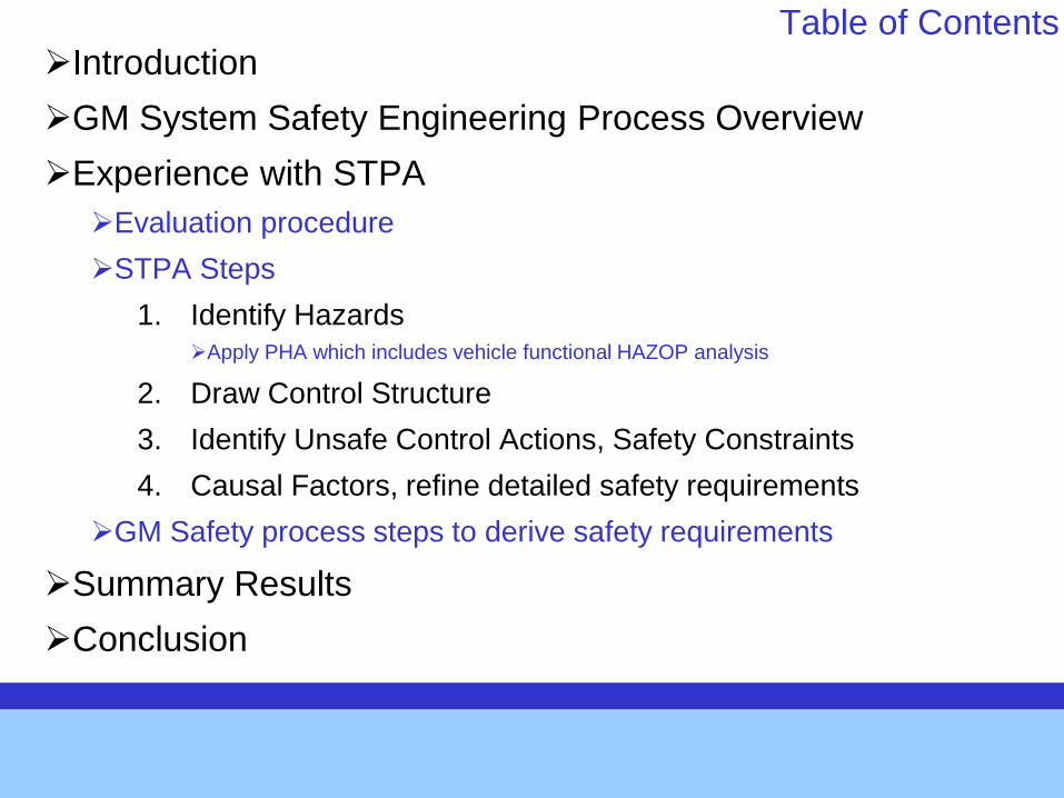
Table of Contents Introduction
GM System Safety Engineering Process Overview
Experience with STPA
Evaluation procedure
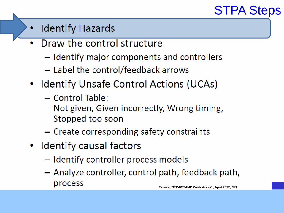
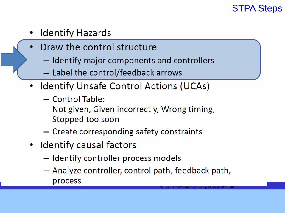
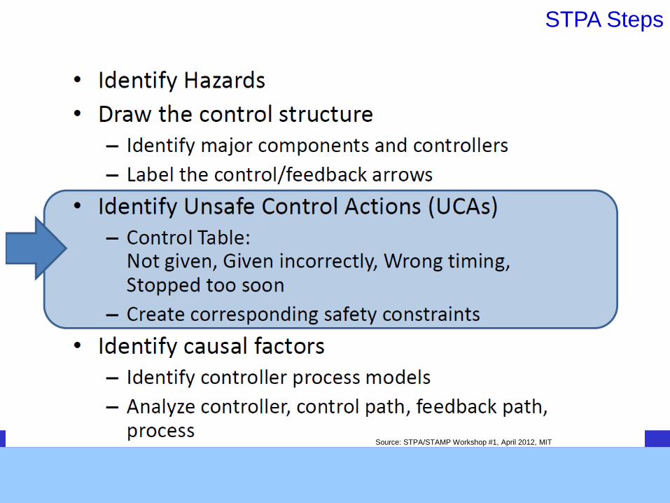
STPA Steps
1. Identify Hazards Apply PHA which includes vehicle functional HAZOP analysis
2. Draw Control Structure
3. Identify Unsafe Control Actions, Safety Constraints
4. Causal Factors, refine detailed safety requirements
GM Safety process steps to derive safety requirements
Summary Results
Conclusion
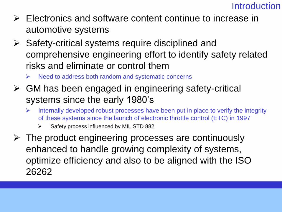
Introduction
Electronics and software content continue to increase in
automotive systems
Safety-critical systems require disciplined and
comprehensive engineering effort to identify safety related
risks and eliminate or control them Need to address both random and systematic concerns
GM has been engaged in engineering safety-critical
systems since the early 1980’s Internally developed robust processes have been put in place to verify the integrity
of these systems since the launch of electronic throttle control (ETC) in 1997
Safety process influenced by MIL STD 882
The product engineering processes are continuously
enhanced to handle growing complexity of systems,
optimize efficiency and also to be aligned with the ISO
26262
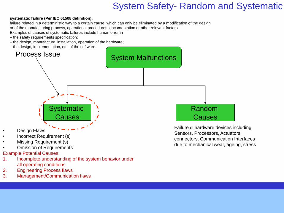
System Safety- Random and Systematic
System Malfunctions
Random
Causes
Failure of hardware devices including
Sensors, Processors, Actuators,
connectors, Communication Interfaces
due to mechanical wear, ageing, stress
Systematic
Causes
• Design Flaws
• Incorrect Requirement (s)
• Missing Requirement (s)
• Omission of Requirements
Example Potential Causes:
1. Incomplete understanding of the system behavior under
all operating conditions
2. Engineering Process flaws
3. Management/Communication flaws
Process Issue
systematic failure (Per IEC 61508 definition):
failure related in a deterministic way to a certain cause, which can only be eliminated by a modification of the design
or of the manufacturing process, operational procedures, documentation or other relevant factors
Examples of causes of systematic failures include human error in
– the safety requirements specification;
– the design, manufacture, installation, operation of the hardware;
– the design, implementation, etc. of the software.
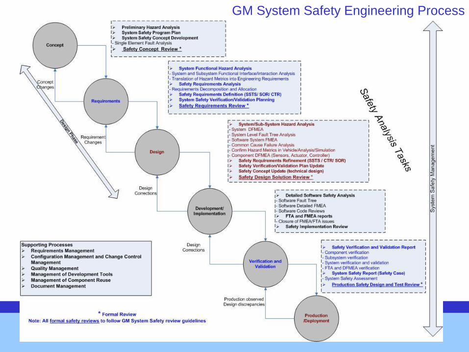
GM System Safety Engineering Process
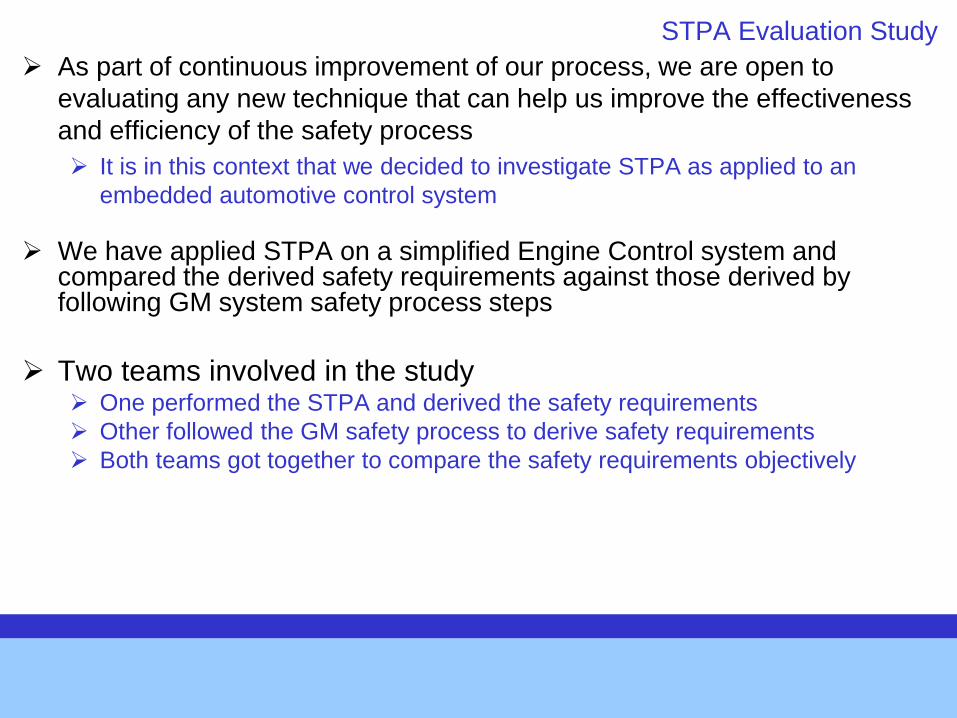
STPA Evaluation Study
As part of continuous improvement of our process, we are open to
evaluating any new technique that can help us improve the effectiveness
and efficiency of the safety process
It is in this context that we decided to investigate STPA as applied to an
embedded automotive control system
We have applied STPA on a simplified Engine Control system and compared the derived safety requirements against those derived by following GM system safety process steps
Two teams involved in the study One performed the STPA and derived the safety requirements
Other followed the GM safety process to derive safety requirements
Both teams got together to compare the safety requirements objectively
STPA Steps
Source: STPA/STAMP Workshop #1, April 2012, MIT
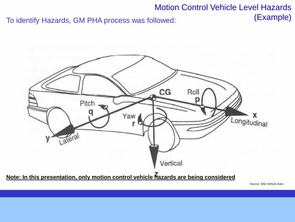
Motion Control Vehicle Level Hazards
(Example)
Source: SAE Vehicle Axes
Note: In this presentation, only motion control vehicle hazards are being considered
To identify Hazards, GM PHA process was followed:
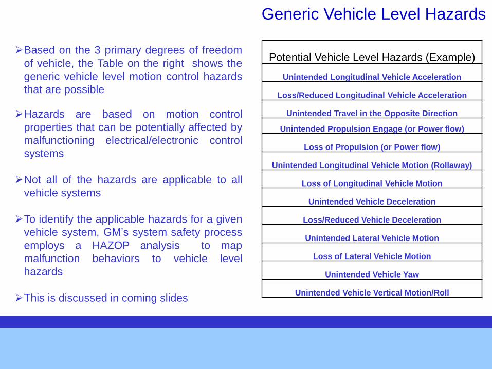
Potential Vehicle Level Hazards (Example)
Unintended Longitudinal Vehicle Acceleration
Loss/Reduced Longitudinal Vehicle Acceleration
Unintended Travel in the Opposite Direction
Unintended Propulsion Engage (or Power flow)
Loss of Propulsion (or Power flow)
Unintended Longitudinal Vehicle Motion (Rollaway)
Loss of Longitudinal Vehicle Motion
Unintended Vehicle Deceleration
Loss/Reduced Vehicle Deceleration
Unintended Lateral Vehicle Motion
Loss of Lateral Vehicle Motion
Unintended Vehicle Yaw
Unintended Vehicle Vertical Motion/Roll
Generic Vehicle Level Hazards
Based on the 3 primary degrees of freedom
of vehicle, the Table on the right shows the
generic vehicle level motion control hazards
that are possible
Hazards are based on motion control
properties that can be potentially affected by
malfunctioning electrical/electronic control
systems
Not all of the hazards are applicable to all
vehicle systems
To identify the applicable hazards for a given
vehicle system, GM’s system safety process
employs a HAZOP analysis to map
malfunction behaviors to vehicle level
hazards
This is discussed in coming slides
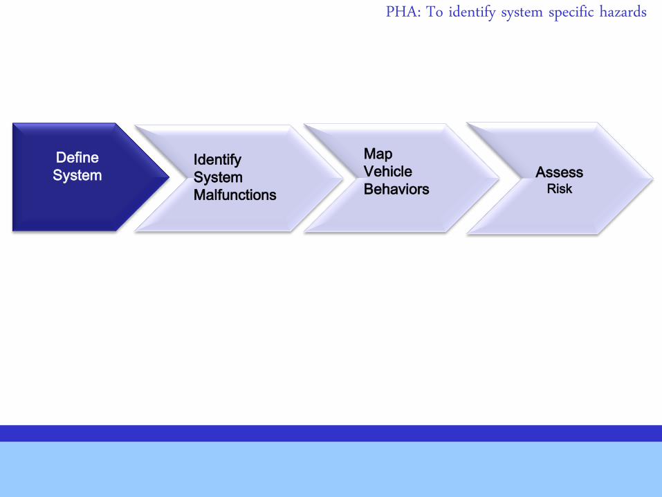
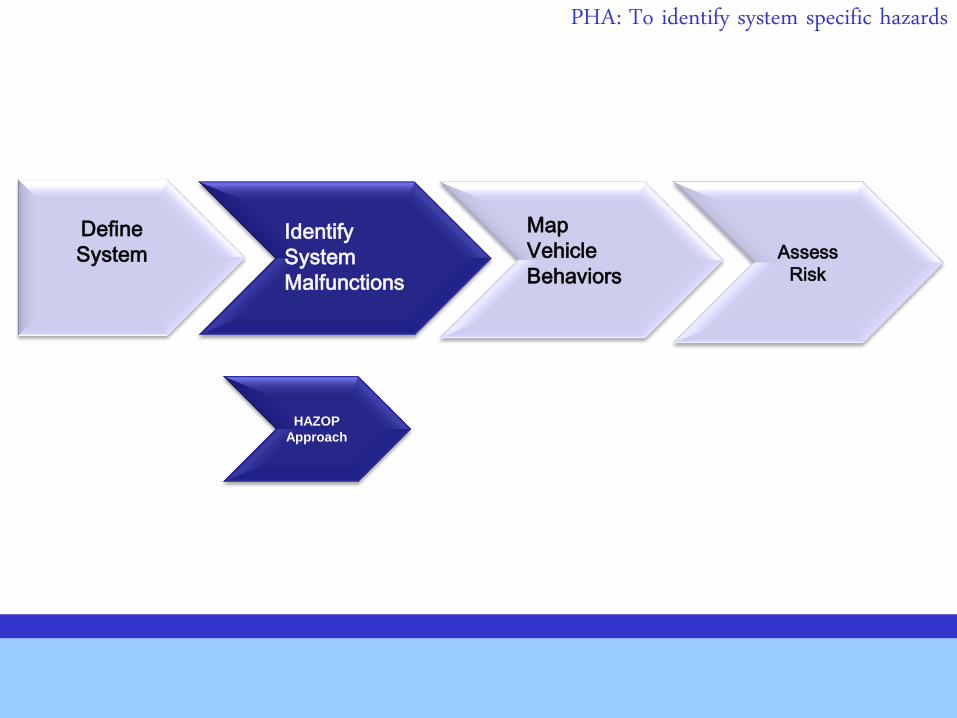
Define
System
Identify
System
Malfunctions
Map
Vehicle
Behaviors
Assess
Risk
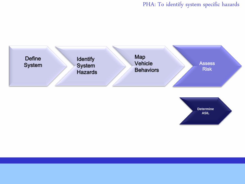
PHA: To identify system specific hazards
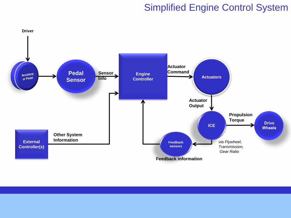
Engine
Controller
Pedal
Sensor Actuators
ICE
Feedback information
Propulsion
Torque
via Flywheel,
Transmission,
Gear Ratio
Driver
Actuator
Command
Actuator
Output
Simplified Engine Control System
External
Controller(s)
Other System
Information
Sensor
Info
Feedback
sensors
Define
System
Identify
System
Malfunctions
Map
Vehicle
Behaviors
Assess
Risk
HAZOP
Approach
PHA: To identify system specific hazards
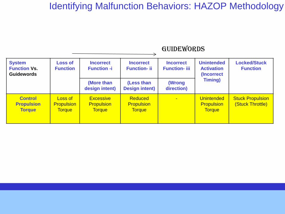
Identifying Malfunction Behaviors: HAZOP Methodology
System
Function Vs.
Guidewords
Loss of
Function
Incorrect
Function -i
Incorrect
Function- ii
Incorrect
Function- iii
Unintended
Activation
(Incorrect
Timing)
Locked/Stuck
Function
(More than
design intent)
(Less than
Design intent)
(Wrong
direction)
Control
Propulsion
Torque
Loss of
Propulsion
Torque
Excessive
Propulsion
Torque
Reduced
Propulsion
Torque
- Unintended
Propulsion
Torque
Stuck Propulsion
(Stuck Throttle)
Guidewords
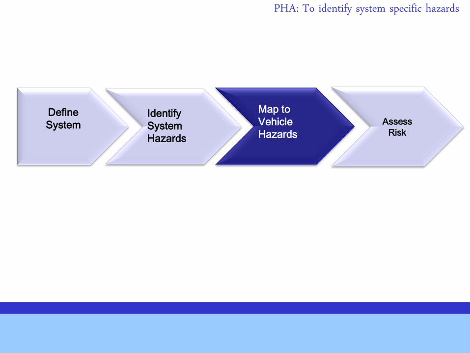
Define
System
Identify
System
Hazards
Map to
Vehicle
Hazards
Assess
Risk
PHA: To identify system specific hazards
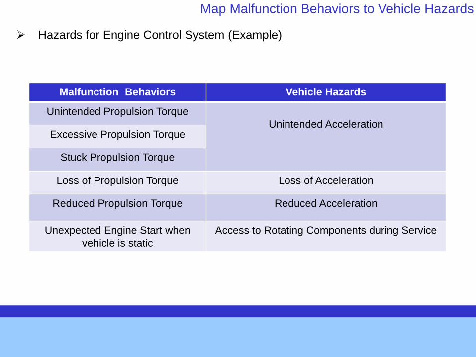
Hazards for Engine Control System (Example)
Map Malfunction Behaviors to Vehicle Hazards
Malfunction Behaviors Vehicle Hazards
Unintended Propulsion Torque
Unintended Acceleration Excessive Propulsion Torque
Stuck Propulsion Torque
Loss of Propulsion Torque Loss of Acceleration
Reduced Propulsion Torque Reduced Acceleration
Unexpected Engine Start when
vehicle is static
Access to Rotating Components during Service
Define
System
Identify
System
Hazards
Map
Vehicle
Behaviors
Assess
Risk
Determine
ASIL
PHA: To identify system specific hazards
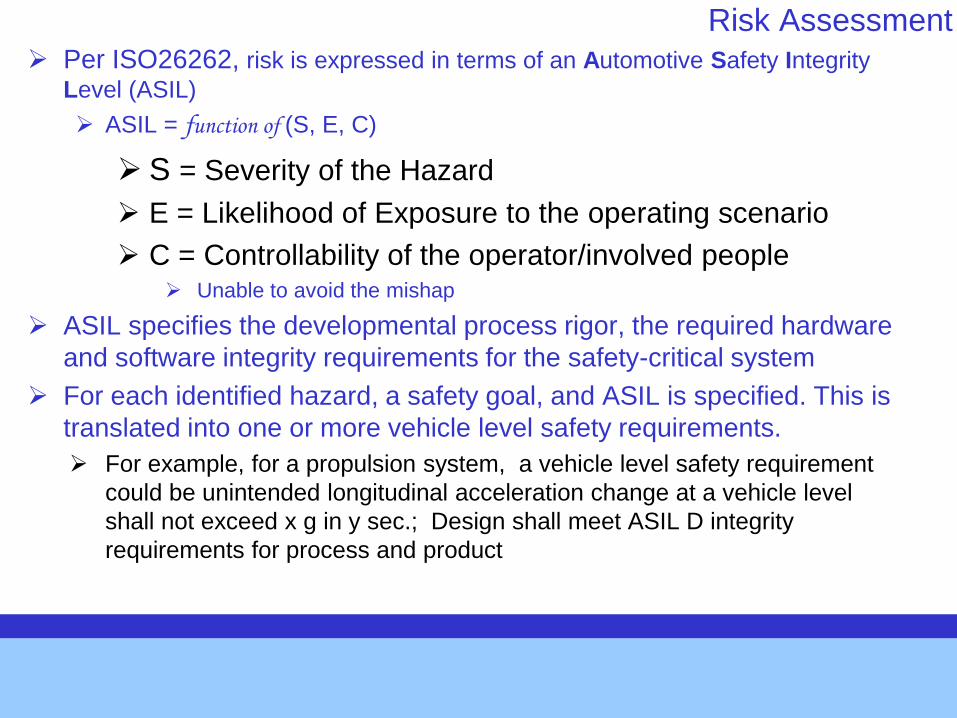
Risk Assessment Per ISO26262, risk is expressed in terms of an Automotive Safety Integrity
Level (ASIL)
ASIL = function of (S, E, C)
S = Severity of the Hazard
E = Likelihood of Exposure to the operating scenario
C = Controllability of the operator/involved people Unable to avoid the mishap
ASIL specifies the developmental process rigor, the required hardware
and software integrity requirements for the safety-critical system
For each identified hazard, a safety goal, and ASIL is specified. This is
translated into one or more vehicle level safety requirements.
For example, for a propulsion system, a vehicle level safety requirement
could be unintended longitudinal acceleration change at a vehicle level
shall not exceed x g in y sec.; Design shall meet ASIL D integrity
requirements for process and product
STPA Steps
Source: STPA/STAMP Workshop #1, April 2012, MIT
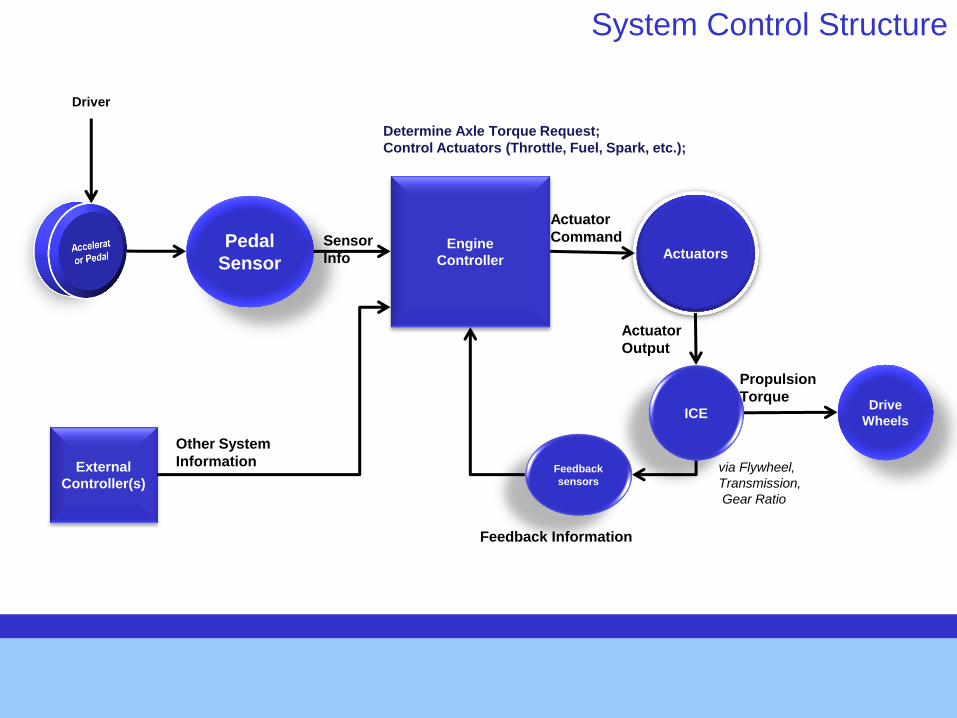
Engine
Controller
Pedal
Sensor Actuators
ICE
Feedback Information
Propulsion
Torque
via Flywheel,
Transmission,
Gear Ratio
Drive
Wheels
Driver
Actuator
Command
Actuator
Output
System Control Structure
External
Controller(s)
Other System
Information
Sensor
Info
Determine Axle Torque Request;
Control Actuators (Throttle, Fuel, Spark, etc.);
Feedback
sensors
STPA Steps
Source: STPA/STAMP Workshop #1, April 2012, MIT
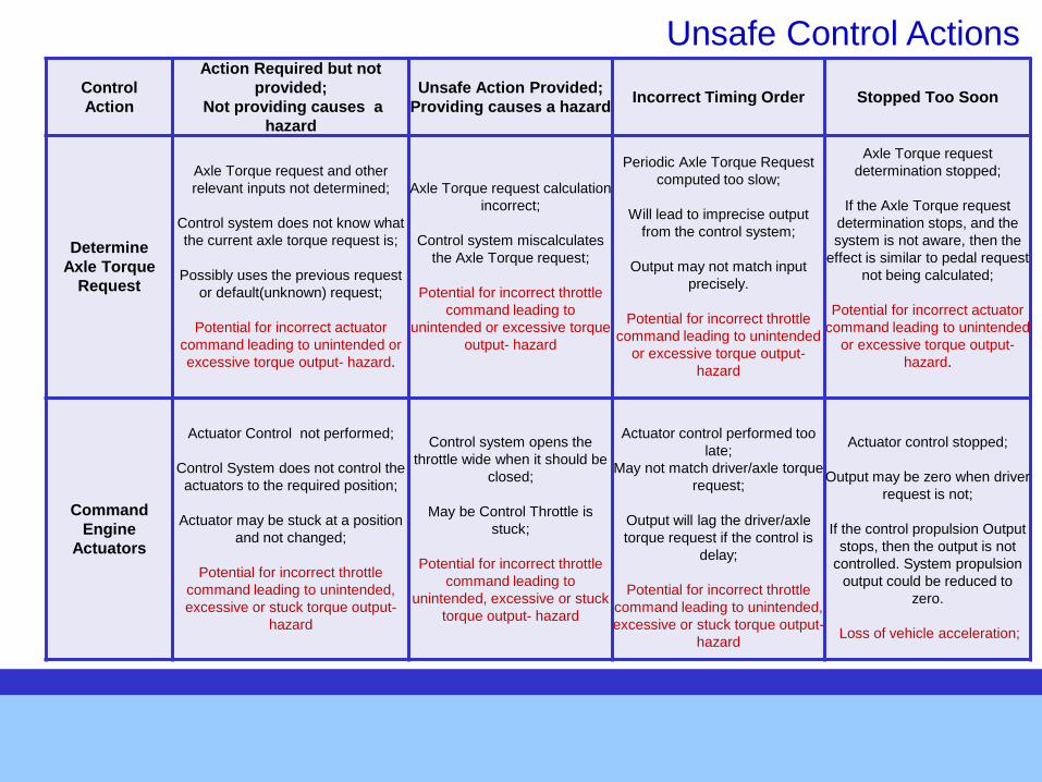
Unsafe Control Actions
Control
Action
Action Required but not
provided;
Not providing causes a
hazard
Unsafe Action Provided;
Providing causes a hazard Incorrect Timing Order Stopped Too Soon
Determine
Axle Torque
Request
Axle Torque request and other
relevant inputs not determined;
Control system does not know what
the current axle torque request is;
Possibly uses the previous request
or default(unknown) request;
Potential for incorrect actuator
command leading to unintended or
excessive torque output- hazard.
Axle Torque request calculation
incorrect;
Control system miscalculates
the Axle Torque request;
Potential for incorrect throttle
command leading to
unintended or excessive torque
output- hazard
Periodic Axle Torque Request
computed too slow;
Will lead to imprecise output
from the control system;
Output may not match input
precisely.
Potential for incorrect throttle
command leading to unintended
or excessive torque output-
hazard
Axle Torque request
determination stopped;
If the Axle Torque request
determination stops, and the
system is not aware, then the
effect is similar to pedal request
not being calculated;
Potential for incorrect actuator
command leading to unintended
or excessive torque output-
hazard.
Command
Engine
Actuators
Actuator Control not performed;
Control System does not control the
actuators to the required position;
Actuator may be stuck at a position
and not changed;
Potential for incorrect throttle
command leading to unintended,
excessive or stuck torque output-
hazard
Control system opens the
throttle wide when it should be
closed;
May be Control Throttle is
stuck;
Potential for incorrect throttle
command leading to
unintended, excessive or stuck
torque output- hazard
Actuator control performed too
late;
May not match driver/axle torque
request;
Output will lag the driver/axle
torque request if the control is
delay;
Potential for incorrect throttle
command leading to unintended,
excessive or stuck torque output-
hazard
Actuator control stopped;
Output may be zero when driver
request is not;
If the control propulsion Output
stops, then the output is not
controlled. System propulsion
output could be reduced to
zero.
Loss of vehicle acceleration;
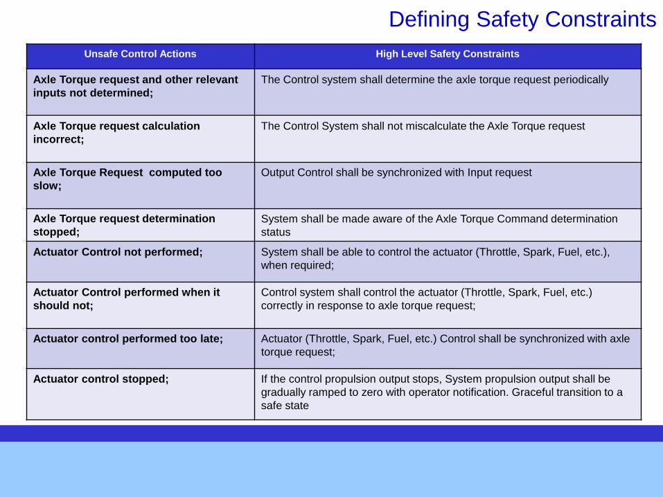
Defining Safety Constraints
Unsafe Control Actions High Level Safety Constraints
Axle Torque request and other relevant
inputs not determined;
The Control system shall determine the axle torque request periodically
Axle Torque request calculation
incorrect;
The Control System shall not miscalculate the Axle Torque request
Axle Torque Request computed too
slow;
Output Control shall be synchronized with Input request
Axle Torque request determination
stopped;
System shall be made aware of the Axle Torque Command determination
status
Actuator Control not performed;
System shall be able to control the actuator (Throttle, Spark, Fuel, etc.),
when required;
Actuator Control performed when it
should not;
Control system shall control the actuator (Throttle, Spark, Fuel, etc.)
correctly in response to axle torque request;
Actuator control performed too late;
Actuator (Throttle, Spark, Fuel, etc.) Control shall be synchronized with axle
torque request;
Actuator control stopped;
If the control propulsion output stops, System propulsion output shall be
gradually ramped to zero with operator notification. Graceful transition to a
safe state
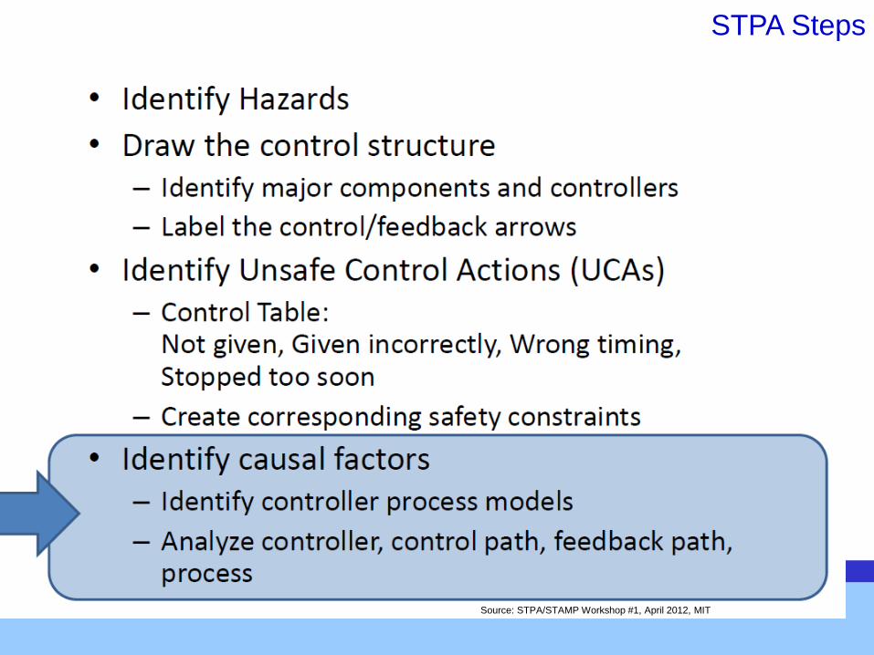
STPA Steps
Source: STPA/STAMP Workshop #1, April 2012, MIT

Engine
Controller
Pedal
Sensor Actuators
ICE
Feedback Information
Propulsion
Torque
via Flywheel,
Transmission,
Gear Ratio
Drive
Wheels
Driver
Actuator
Command
Actuator
Output
STPA Analysis: Causal Factors
External
Controller(s)
Other System
Information
Sensor
Info
Determine Axle Torque Request;
Control Actuators (Throttle, Fuel, Spark, etc.);
• Incorrect/Inadequate control of safety
critical outputs
• Incorrect requirements, design flaws,
• Calibration changes, hardware integrity
issues
• Incorrect or missing or delayed
sensor information
• Requirements, design flaws,
• Changes, hardware integrity
issues
Incorrect/delayed/
inadequate
operation
• Incorrect or missing external
information
• Requirements, design flaws,
• Changes, hardware integrity
issues
Incorrect or missing
or delayed sensor
information
EMI
Component faults,
changes overtime,
mechanical issues,
disturbances due to
placement in the
vehicle
Component Faults,
changes overtime,
unidentified or out-of range
disturbances
Input Processing
Input Arbitration
Compute Cmnds
Control Outputs
Component Faults,
changes overtime,
unidentified or out-of range
disturbances, Stuck
Control, mechanical issues,
EMI
Feedback
sensors
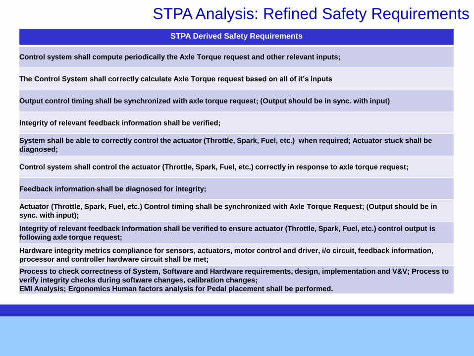
STPA Analysis: Refined Safety Requirements
STPA Derived Safety Requirements
Control system shall compute periodically the Axle Torque request and other relevant inputs;
The Control System shall correctly calculate Axle Torque request based on all of it’s inputs
Output control timing shall be synchronized with axle torque request; (Output should be in sync. with input)
Integrity of relevant feedback information shall be verified;
System shall be able to correctly control the actuator (Throttle, Spark, Fuel, etc.) when required; Actuator stuck shall be
diagnosed;
Control system shall control the actuator (Throttle, Spark, Fuel, etc.) correctly in response to axle torque request;
Feedback information shall be diagnosed for integrity;
Actuator (Throttle, Spark, Fuel, etc.) Control timing shall be synchronized with Axle Torque Request; (Output should be in
sync. with input);
Integrity of relevant feedback Information shall be verified to ensure actuator (Throttle, Spark, Fuel, etc.) control output is
following axle torque request;
Hardware integrity metrics compliance for sensors, actuators, motor control and driver, i/o circuit, feedback information,
processor and controller hardware circuit shall be met;
Process to check correctness of System, Software and Hardware requirements, design, implementation and V&V; Process to
verify integrity checks during software changes, calibration changes;
EMI Analysis; Ergonomics Human factors analysis for Pedal placement shall be performed.
Table of Contents Introduction
GM System Safety Engineering Process Overview
Experience with STPA
Evaluation procedure
STPA Steps
1. Identify Hazards Apply PHA which includes vehicle functional HAZOP analysis
2. Draw Control Structure
3. Identify Unsafe Control Actions, Safety Constraints
4. Causal Factors, refine detailed safety requirements
GM Safety process steps to derive safety requirements steps
Summary Results
Conclusion

System Safety
Program
Plan
Directs and manages the
safety process execution
Concept Phase
Requirements Phase
Design Phase
GM Safety Process: Safety Requirements Derivation
Refine
requirements
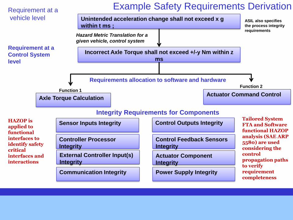
Unintended acceleration change shall not exceed x g
within t ms ;
Incorrect Axle Torque shall not exceed +/-y Nm within z
ms
Hazard Metric Translation for a
given vehicle, control system
Axle Torque Calculation Actuator Command Control
Function 1 Function 2
Requirement at a
vehicle level
Requirement at a
Control System
level
Requirements allocation to software and hardware
Sensor Inputs Integrity
Controller Processor
Integrity
Control Outputs Integrity
External Controller Input(s)
Integrity
Control Feedback Sensors
Integrity
Actuator Component
Integrity
Communication Integrity Power Supply Integrity
Integrity Requirements for Components
Example Safety Requirements Derivation
Tailored System FTA and Software functional HAZOP analysis (SAE ARP 5580) are used considering the control propagation paths to verify requirement completeness
HAZOP is applied to functional interfaces to identify safety critical interfaces and interactions
ASIL also specifies
the process integrity
requirements
Table of Contents Introduction
GM System Safety Engineering Process Overview
Experience with STPA
Evaluation procedure
STPA Steps
1. Identify Hazards Apply PHA which includes vehicle functional HAZOP analysis
2. Draw Control Structure
3. Identify Unsafe Control Actions, Safety Constraints
4. Causal Factors, refine detailed safety requirements
GM Safety process steps to derive safety requirements steps
Summary Results
Conclusion
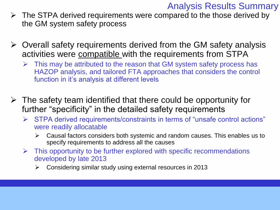
Analysis Results Summary The STPA derived requirements were compared to the those derived by
the GM system safety process
Overall safety requirements derived from the GM safety analysis activities were compatible with the requirements from STPA This may be attributed to the reason that GM system safety process has
HAZOP analysis, and tailored FTA approaches that considers the control function in it’s analysis at different levels
The safety team identified that there could be opportunity for further “specificity” in the detailed safety requirements STPA derived requirements/constraints in terms of “unsafe control actions”
were readily allocatable
Causal factors considers both systemic and random causes. This enables us to specify requirements to address all the causes
This opportunity to be further explored with specific recommendations developed by late 2013
Considering similar study using external resources in 2013
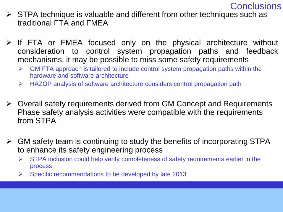
Conclusions STPA technique is valuable and different from other techniques such as
traditional FTA and FMEA
If FTA or FMEA focused only on the physical architecture without consideration to control system propagation paths and feedback mechanisms, it may be possible to miss some safety requirements GM FTA approach is tailored to include control system propagation paths within the
hardware and software architecture
HAZOP analysis of software architecture considers control propagation path
Overall safety requirements derived from GM Concept and Requirements Phase safety analysis activities were compatible with the requirements from STPA
GM safety team is continuing to study the benefits of incorporating STPA to enhance its safety engineering process STPA inclusion could help verify completeness of safety requirements earlier in the
process
Specific recommendations to be developed by late 2013
Acknowledgements
Thanks to the support of GM Engine Control Safety team members Rich Kulas and Tim Hartrey for supporting this study

Thank You

Backup
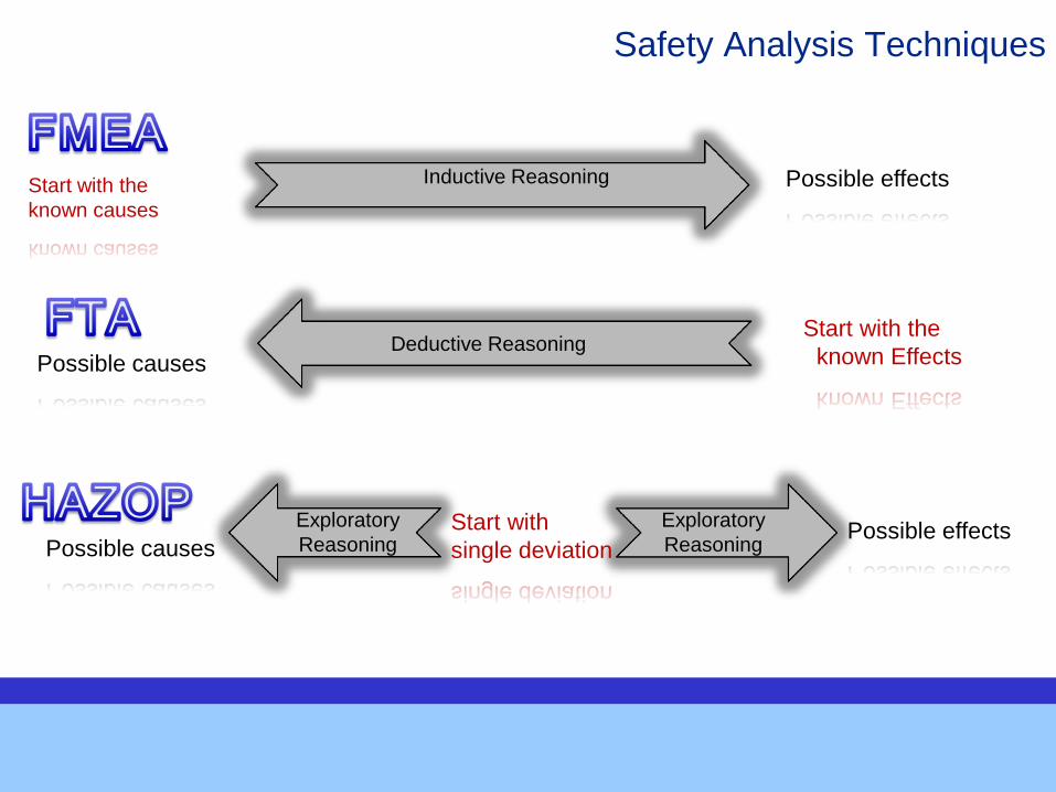
Start with the
known Effects
Inductive Reasoning Start with the
known causes
Possible effects
Possible causes Deductive Reasoning
Start with
single deviation Possible causes Possible effects
Exploratory
Reasoning
Exploratory
Reasoning
Safety Analysis Techniques
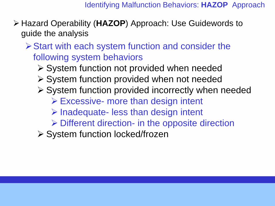
Identifying Malfunction Behaviors: HAZOP Approach
Hazard Operability (HAZOP) Approach: Use Guidewords to
guide the analysis
Start with each system function and consider the
following system behaviors
System function not provided when needed
System function provided when not needed
System function provided incorrectly when needed
Excessive- more than design intent
Inadequate- less than design intent
Different direction- in the opposite direction
System function locked/frozen
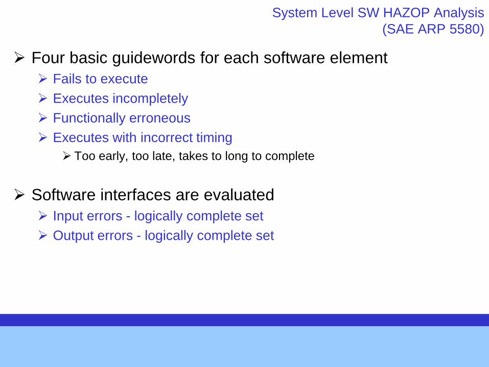
System Level SW HAZOP Analysis
(SAE ARP 5580)
Four basic guidewords for each software element
Fails to execute
Executes incompletely
Functionally erroneous
Executes with incorrect timing
Too early, too late, takes to long to complete
Software interfaces are evaluated
Input errors - logically complete set
Output errors - logically complete set