
COMPARISON OF MESOPOROUS CARBON/CARBON ...
45
COMPARISON OF MESOPOROUS CARBON/CARBON SUPERCAPACITOR AND NiO / MESOPOROUS CARBON HYBRID ELECTROCHEMICAL CAPACITOR TERESSA A/P LUDU NATHAN UNIVERSITI SAINS MALAYSIA 2008
Transcript of COMPARISON OF MESOPOROUS CARBON/CARBON ...
COMPARISON OF MESOPOROUS CARBON/CARBON SUPERCAPACITOR AND NiO / MESOPOROUS
CARBON HYBRID ELECTROCHEMICAL CAPACITOR
TERESSA A/P LUDU NATHAN
UNIVERSITI SAINS MALAYSIA
2008
COMPARISON OF MESOPOROUS CARBON/CARBON SUPERCAPACITOR
AND NiO / MESOPOROUS CARBON HYBRID ELECTROCHEMICAL CAPACITOR
By
TERESSA A/P LUDU NATHAN
Thesis submitted in fulfillment of the requirements for the degree
of Masters of Science
MAY 2008
ii
ACKNOWLEDGEMENTS
I would like to express my gratitude to my supervisor Professor Dr. Ahmad
Fauzi Mohd Noor who has always been there to help me despite his schedules with
research, administration work and teaching. He has been extremely helpful in not only
suggesting worthwhile content and research strategy, but also offering advice on
authoring and effective thesis writing skills. Words fall short to express his enthusiasm
and invaluable help towards executing this research tasks in USM.
Sincere thanks are extended to Assoc. Prof. Azizan Aziz, the Deputy Dean of
Post Graduate studies in the School of Materials and Mineral Sciences for granting me
the permission to use electrochemical workstation and Arbin battery testing system,
which was the major contribution in obtaining the electrochemical data for this thesis.
I am deeply indebted to my field supervisor Assoc. Prof. Dr. SRS Prabaharan
from the University of Nottingham, Malaysia Campus for his efforts and time in
producing this worthwhile thesis. He has supported and encouraged me in many ways
in terms of valuable ideas and research techniques. His stimulating suggestions and
encouragement helped me finish thesis on time. Thanks are also due to his valuable
time and advice in thesis write-up.
Without these scholars, the completion of this thesis would have been an
impossible proposition.
Special thanks go to Prof. A R West, Head of Engineering Materials Dept., The
University of Sheffield, UK, and his post docs, Dr. Gabby and Dr. Deni Pasero who
rendered me their guidance in all possible ways and helped me using Tony’s
laboratory facilities. The initial experimental work, which was carried out in his lab, has
benefited me a lot and it was used as a yardstick to complete this work.
I would also like to gratefully acknowledge the support of some very special individuals,
Mr. Sunnil Kraemer, Managing Director of IKA Works (Asia) Sdn Bhd, Mr. Muthu,
(TEM) from School of Biology, Mr. Rashid (FE-SEM) from School of Material and

iii
Mineral Sciences, Mr. Karuna (XRD) from School of Physics and Mr. Suhaimi
(Electronics lab) from School of Material and Mineral Science who have been directly
or indirectly of help offering their encouragement and support.
Special thanks to Dr. Siluvai Michael, SSN Engineering College, India for
sharing her knowledge in this field during the early days of my studies. Last but not
least; I would like to thank my parents and siblings who had perpetually encouraged
and supported me throughout this thesis work.
iv
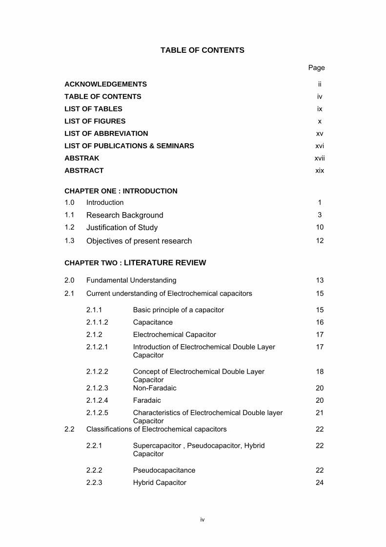
TABLE OF CONTENTS
Page ACKNOWLEDGEMENTS ii
TABLE OF CONTENTS iv
LIST OF TABLES ix
LIST OF FIGURES x
LIST OF ABBREVIATION xv
LIST OF PUBLICATIONS & SEMINARS xvi
ABSTRAK xvii
ABSTRACT xix
CHAPTER ONE : INTRODUCTION
1.0 Introduction 1
1.1 Research Background 3
1.2 Justification of Study 10
1.3 Objectives of present research 12
CHAPTER TWO : LITERATURE REVIEW
2.0 Fundamental Understanding 13
2.1 Current understanding of Electrochemical capacitors
15
2.1.1 Basic principle of a capacitor 15
2.1.1.2 Capacitance 16
2.1.2 Electrochemical Capacitor 17
2.1.2.1 Introduction of Electrochemical Double Layer Capacitor
17
2.1.2.2 Concept of Electrochemical Double Layer Capacitor
18
2.1.2.3 Non-Faradaic 20
2.1.2.4 Faradaic 20
2.1.2.5 Characteristics of Electrochemical Double layer Capacitor
21
2.2 Classifications of Electrochemical capacitors
22
2.2.1 Supercapacitor , Pseudocapacitor, Hybrid Capacitor
22
2.2.2 Pseudocapacitance 22
2.2.3 Hybrid Capacitor 24
v
2.2.4 Electrolytic capacitors 25
2.2.5 Main Applications of EDLC 26
2.2.5.1 Current and potential applications for EDLC 26
2.3 Overview of electrodes and electrolytes 29
2.3.1 Nomenclature of EDLC 29
2.4 Electrode material 29
2.4.1 Carbon 29
2.4.1.2 Desirable properties of carbon for electrochemical applications
31
2.4.1.3 Porous Carbon 31
2.4.1.4 Activated Carbons 33
2.4.1.5 Carbon Aerogels 34
2.4.1.6 Carbon Nanotubes 34
2.4.2 Metal Oxides 35
2.4.3 Polymers 36
2.5 Electrolyte 37
2.5.1 Aqueous Electrolyte 38
2.5.2 Non-Aqueous (organic) Electrolyte 39
2.6 Separator 40
2.7 Binder and current collector 40
2.8 Cell Design 41
2.9 Comparison of Capacitor, EDLC and battery 42
2.10 Choice of Electrode materials: A rationale 44
2.10.1 Nanostructured NiO as positive electrode 44
2.10.2 Soft-chemistry Approach for synthesis of transition metal oxides
46
2.10.3 Synthesis of nanostructured NiO
47
2.10.4 Nanostructured (Mesoporous) carbon as negative electrode
48
2.11 Effect on equivalent series resistant (ESR) 49
2.11.1 Additive carbon 52
CHAPTER THREE : EXPERIMENTAL METHODOLOGY
3.1 Introduction 53
vi
3.1.1 Methodology overview 53
3.2 Electrode Preparation
3.2.1 Mesoporous Carbon and additive carbon 54
3.2.2 Carbon Black Electrode Preparation 57
3.3 Soft-chemistry synthesis
58
3.3.1 Synthesis of nanostructured NiO
58
3.3.2 Nickel Oxide Electrodes : Preparation
60
3.3.3 Three-electrode electrochemical cell
construction
60
3.4 Fabrication of Symmetric and Asymmetric EC
61
3.5 Instrumentation techniques employed 62
3.5.1 Phase Analysis (XRD) 62
3.6 Morphological studies
3.6.1 Field Emision Scanning Electron Microscopy
(FESEM)
63
3.6.2 Transmission Electron Microscopy (TEM) /
Selected Area Electron Diffraction (SAED)
64
3.6.2 Thermogravimetic Analysis (TG) 65
3.7 Electrochemical Techniques 65
3.7.1 Cyclicvoltammetry (CV) 65
3.7.2 Galvanostatic – constant current charge and
discharge measurements
67
3.7.3 EIS – AC Impedance Spectroscopy 69
CHAPTER FOUR : RESULT AND DISCUSSION
4.1
Physical Characterization of Nanostructured (Mesoporous)
Carbon as negative electrode
71
4.1.1 XRD 71 4.1.2 TEM 72 4.1.3 FE-SEM 73 4.1.4 Electrochemical impedance spectroscopy (EIS) 74 4.1.5 Cyclic voltammetry (CV) 81
vii
4.1.6 Galvanostatic – constant current charge and
discharge measurements
86
4.1.7 Ragone plot – Power density and Energy
Density
91
4.2 Studies on additive carbons in the composite EM2K nanoporous carbon electrode: Effect on ESR improvisation
92
4.2.1 Electrochemical impedance spectroscopy (EIS) 93
4.2.2 Galvanostatic – constant current charge and
discharge measurements
95
4.2.3 Ragone plot – Power density and Energy
Density
100
4.3 Low temperature Synthesis of Nanostructured NiO for
Electrochemical Capacitors
104
4.3.1 Synthesis of Nanostrucutred NiO using a
solvothermal low temperature process
104
4.3.2 Physio-chemical Characterization 105
4.3.2.1 Thermogravimetric analysis (TG) 105
4.3.2.2 Phase Analysis 106
4.3.2.3 FE-SEM/HR-TEM analysis 107
4.3.3 Electrochemical Studies 111
4.3.3.1 Single Electrode Behavior vs. standard calomel
electrode
111
4.4 Asymmetric Hybrid capacitor NiO (+)/ Mesoporous Carbon
EM2K
115
4.4.1 NiO(+)/EM2K (assembled) based on single
electrode characterization as electrodes for ECs
115
4.4.2 AC-impedance (Nyquist) Analysis (EIS) 116
4.4.3 Current-voltage response using Cyclic Voltammetry
119
4.4.4 Constant current charge-discharge analysis 121
4.4.5 Ragone Plot - Power density versus Energy
density
125
CHAPTER FIVE : SUMMARY AND CONCLUSION
127

viii
5.1 Summary 127
5.2 Conclusion 130
5.3 Future recommendation 131
REFERENCES 132
APPENDIX 139
PAPER PUBLICATION 144
ix
LIST OF TABLES Page
2.1 Comparison of Capacitor and Double Layer Capacitor 43
2.2 Comparison of Double Layer Capacitor and battery 44
3.1 Physical properties of EM2K 55
3.2 Summary of physical properties of EM2K, BP2K and AB 57
3.3 Different type of composition of Emperor 2000 (EM2K) used in
this work and its cell assembly.
57
3.4 Asymmetric EC configuration using NiO 58
4.1 Summary of values of specific capacitance values obtained at
different scan rates.
84
4.2 summary of the Specific capacitance obtain ranging from 13.28
F/g to 27.35 F/g at different current density in ascending
manner
88
4.3 Summary of the overall capacitance obtained from three
different methods ( AC Impedance, cyclic voltammetry and
Gavanostatic).
90
4.4 Summary of specific power density and specific energy density
taken obtained different current density.
92
4.5 Summary of the ESR values and the specific capacitances
obtained in all three carbon composition
94
4.6 EM2K with 10% of AB as electrode at different current
densities
99
4.7 EM2K with 10% of BP2K as electrode at different current
density
100
4.8 Specific Capacitance Comparison of cell A, B & C at different
current density
100
4.9 Summary of the power and the energy density comparison of
all three carbon composites
101
4.10 Summary of specific capacitance obtained at different scan
rates
121
4.11 Summary of the specific capacitance values achieved for
NiO/C hybrid cell obtained by means of constant current
charge-discharge technique.
124
4.12 Power density and energy density at various scan rate 126
5.1 Energy density and Power density comparison of the four EC configurations studied in this work
129
x
LIST OF FIGURES
Page
1.1 FE-SEM image of the as-grown single walled CNT 6
2.1 Classification of different type of commercially available
capacitors.
14
2.2 Principle of electrostatic induction 15
2.3 Behavior of electrolyte in ion ( positive charge) in the pore
when charged and discharge
18
2.4 Helmholtz double layer 19
2.5 Typical distribution of charges at the interface and its
electrode potential before and after charging.
20
2.6 A Li-doped graphite in the anode of the hybrid capacitor that
intercalates Li+ ions into its interlayer in the charging process
and de-intercalates Li+ ions in the discharging process
24
2.7 Working principle of a hybrid capacitor. 25
2.8 Illustration of a mesoporous activated carbon structure and
EDLC configuration.
30
2.9 IUPAC classification of porous materials 33
2.10 EDLC Cell construction 42
2.11 Comparison chart indicating the specific power density and
energy density of capacitor, supercapacitors, batteries and
fuel cells.
43
2.12 Equivalent circuit describing the impedance behavior of a
typical double layer capacitor
50
3.1 Flow chart of the methodology approached 54
3.2 TEM image of acetylene black. 56
3.3 TEM image of Black pearls 2000. 56
3.4 Flow chart showing the soft chemistry method to synthesis of
Nickel oxide by using a new solvolysis technique at low
temperature
59
3.5 Open beaker three electrode cell, comprising active material
electrodes (composite electrode cut into a pre-determined
size) as working electrode, saturated calomel electrode using
saturated KCl solution as the reference electrode and
platinum foil as the counter electrode.
61

xi
3.6 Stainless steel cell used in EC cell fabrication 62
3.7 Comparison of ideal and real cyclic voltammograms 66
3.8 Typical frequency dependent impedance plot of EDLC drawn
Z” (imaginary impedance due to capacitive components) vs.
real impedance Z’
69
4.1 XRD Pattern of Emperor 2000 carbon (EM2K) 71
4.2 TEM Image of Emperor 2000 carbon (EM2K) 72
4.3 (a) Nanoporous (mesoporosity) morphology with particle sizes within the range, 9-13 nm. Image x 50,000 magnification
73
4.3 (b) Nanoporous (mesoporosity) morphology with particle sizes within the range, 9-13 nm. Image x 100,000 magnification
74
4.4(a) The Nyquist complex plane impedance plot, Z″ (real) versus Z′ (imaginary), the real and the imaginary components of the impedance are obtained in variant of frequency range from 10 kHz to 1mHz.
75
4.4(b) Exploded view of the Nyquist plot within the range of 10kHz
to 10Hz
75
4.5 Specific capacitance vs Frequency of EM2K symmetric configuration (soaked in Electrolyte for 1 hr)
77
4.6 (a) Comparison of Nyquist plots for similar electrodes soaked in two different condition (atmospheric pressure and vaccum (degassed))
78
4.6 (b) Exploded view of two Nyquist comparison of similar electrodes soaked in two different condition (atmospheric pressure and vaccum (degassed))
78
4.7 Comparison of Specific capacitance vs Frequency plot for similar electrodes soaked in two different condition (atmospheric pressure and vaccum (degassed))
80
4.8 RC plot depicting the region I, the propagation occurs along the more expanded mesopore structures and the region II that could be ascribed to the penetration of ac signal into the narrow mesopores.
81
4.9 Rate dependant voltammograms of EM2K symmetric cell
84
4.10 Cyclic voltammogram of EM2K symmetric cell at a scan rate of 10mV/s
85
xii
4.11 Cyclic voltammogram of EM2K symmetric cell at a scan rate of 100mV/s
85
4.12 Variation of Specific Capacitances with respect to scan rate
86
4.13 Charge/Discharge profile of EM2K similar electrode obtained at different current densities.
88
4.14 (a) Galvanostatic-Charge/Discharge of EM2K similar electrode at 56.6mA/cm2
89
4.14 (b) IR drop observed during Charge/Discharge of EM2K similar electrode at 56.6mA/cm2
89
4.15 (a) Galvanostatic-Charge/Discharge of EM2K similar electrode at 11.3mA/cm2
90
4.15 (b) IR drop observed during Charge/Discharge of EM2K similar electrode at 11.3mA/cm2
90
4.16 Ragone Plot of EM2K similar electrode exhibiting the relationship of power and energy density
92
4.17 Nyquist complex plane impedance plot, Z″ (real) versus Z′
(imaginary) obtained in variant of frequency range from 10
kHz to 1mHz comparing all three cell with different
composition.
94
4.18 Specific Capacitance vs Frequency comparing all three cell
with different composition.
95
4.19(a) Galvanostatic-Charge/Discharge profile of Similar Electrodes
of Emperor 2000/AB at different current densities
96
4.19(b) Galvanostatic-Charge/Discharge profile of Similar Electrodes
of EM2K with 10% of BP2K as electrode at different current
density
96
4.20(a) Similar Electrodes of Emperor 2000/AB - Galvanostatic-
Charge/Discharge at 56.6mA/cm2
97
4.20(b) Similar Electrodes of Emperor 2000/BP2K -Galvanostatic-
Charge/Discharge at 56.6mA/cm2
97
4.20(c) Similar Electrodes of Emperor 2000/AB -Galvanostatic-
Charge/Discharge at 11.3 mA/cm2
98
4.20(d) Similar Electrodes of Emperor 2000/BP2K -Galvanostatic-
Charge/Discharge at 11.3 mA/cm2
98
4.21 The charge/discharge behavior of composite carbons ( AB +
BP2K) as compared to virgin EM2K at 28.3 mA/cm2 current
density
99
xiii
4.22 Comparison of Energy Density (Wh/kg) and power density
(W/kg) of Similar Electrodes of EM2K/ AB at different current
densities.
102
4.23 Comparison of Energy Density (Wh/kg) and power density
(W/kg) of Similar Electrodes of EM2K/ BP2K at different
current densities
103
4.24 Comparison of Energy Density (Wh/kg) and power density
(W/kg) of Similar Electrodes of EM2K, EM2K/ AB and
EM2K/BP2K at different current densities
103
4.25 TGA Analysis of nickel nitrate precursor before NiO formation 106
4.26 X-ray diffractogrmas of NiO at different heat treatment
temperature
107
4.27 FE-SEM picture of NiO heated at (a) 400oC , (b) 600 oC and
(c) 800 oC in air for 1 hr
108
4.28 HR-TEM picture of NiO heated at 400oC (1h/air) (Inset: Bright
field SAED pattern of the NiO heated at 400°C/ 1hr in air)
110
4.29 EDAX analysis of nickel oxide calcined at 400oC 110
4.30 Scan rate dependent cyclic voltammetry of nanostructured
NiO against SCE reference electrode.
111
4.31 Specific Capacitance vs Potential plot of nanostructured NiO
against SCE reference electrode.
113
4.32 Nyquist plot (Z” vs Z’) NiO(+)/Na+/C(-) hybrid cell illustrating
the capacitive behaviour (spike-like frequency response) at
frequencies below 170 Hz
117
4.33 Specific Capacitance vs frequency of NiO(+)/Na+/C(-) hybrid
cell
118
4.34 Cyclic voltametry of NiO(+)/Na+/C(-) hybrid cell at different
scan rate
120
4.35 (a) Cyclic voltametry of NiO(+)/Na+/C(-) hybrid cell at 5mV/s 120
4.35 (b) Cyclic voltametry of NiO(+)/Na+/C(-) hybrid cell at 100mV/s 120
4.36 Specific capacitance vs Potential plot of NiO(+)/Na+/C(-)
hybrid cell at different scan rate
121
4.37 Galvanostatic charge/discharge cycles at different current
densities. (a) 56.6 mA/cm2 (b) 28.3 mA/cm2, (c) 11.3 mA/cm2
(d) 5.7 mA/cm2 (e) 2.8 mA/cm2 (f) 0.6 mA/cm2
123
xiv
4.39 (a) Galvanostatic-Charge/Discharge at 0.6mA/cm2 of
NiO(+)/Na+/C(-) hybrid cell
124
4.39 (b) Galvanostatic-Charge/Discharge at 56.6 mA/cm2 of
NiO(+)/Na+/C(-) hybrid cell
125
4.40 Power density vs. energy density relationship of
NiO(+)/Na+/C(-) hybrid cell
126
5.1 Comparison of Ragone plot of the four EC configurations studied in this work
129
xv
LIST OF ABBREVIATION
1.1 EC - Electrochemical Capacitor
1.2 SC - Supercapacitor
1.3 UC- UItracapacitor
1.4 EDLC - Electrochemical Double layer Capacitor
1.5 ESR - Equivalent Series Resistant
1.6 CV - Cyclic Voltametry
1.7 EM2K- Emperor 2000
1.8 BP2K – Black Pearls 2000
1.9 AB – Acetalyne Black
xvi
LIST OF PUBLICATIONS & SEMINARS
1.1 1.2
Nanostructured NiO for Electrochemical Capacitors: Synthesis and Electrochemical properties Teressa L Nathan, Azizan Aziz, Ahmad Fauzi Noor , SRS Prabaharan ICMAT 2007 Singapore Solid State Electrochem DOI 10.1007/s10008-007-0465-3, Springer-Verlag 2007 Low temperature Synthesis of Nanostructured NiO for Electrochemical Capacitors, Teressa L Nathan, Azizan Aziz, Ahmad Fauzi Noor , SRS Prabaharan, Presented at the 4th COE Workshop on Regional Network Formation for Enhancing Research and Education on Materials Engineering, Bandung (Indonesia) June 26-28, 2006 organised by Institute Technology Bandung Indonesia and Nagaoka University Technology, Japan. Paper submitted to Advances in Technology of Materials and Materials Processing Journal (ATM ISSN 1440-0731)
140
xvii
PERBANDINGAN ANTARA KARBON/KARBON SUPERKAPASITOR DAN NIO/ KARBON MESOOLIANG KAPASITOR ELEKTROKIMIA HIBRID
ABSTRAK
Kapasitor elektrokimia adalah satu teknologi mantap yang mempunyai potensi
tinggi sebagai peranti penyimpan tenaga. Keupayaannya memenuhi keperluan tenaga
semasa, dari sudut ketumpatan tenaga dan kuasa yang tinggi, membolehkannya
menjadi alternatif kepada bateri dalam aplikasi-aplikasi khusus yang memerlukan
kuasa output yang besar. Bahagian pertama kajian tertumpu kepada pencirian bahan
berkarbon tanpa grafit, khususnya karbon hitam Emperor 2000 (EM2K). Sel
elektrokimia dibentuk dengan pellet EM2K yang kemudiannya direndam ke dalam
larutan elektrolit 2M NaOH dan diuji pada pelbagai ketumpatan arus untuk melihatkan
kelakuan cas/discasnya. Voltametri siklik dan ciri-ciri impedans juga dianalisis dan
disimpulkan memberi kapasitans sebanyak 20F/g. Kekonduksian elektrod adalah
penting mempengaruhi rintangan bersiri ekuivalen (ESR) bagi sel kapasitor.
Pengurangan ESR dapat dilakukan dengan meningkatkan kekonduksian elektrik untuk
elektrod karbon dengan cara menambahkan karbon hitam berkekonduksian tinggi,
seperti asetalin hitam (AB) dan/atau Black Pearl 2000 (BP2K). Komposit elektrod yang
mengandungi karbon hitam berkekonduksian tinggi ini, dengan 10% berat AB dan/atau
BP2K, telah menghasilkan kapasitans tentu 24 F/g dan 39 F/g masing-masing. Dalam
kajian ini juga, nikel oksida (NiO) dipilih sebagai elektrod positif disebabkan sifat-sifat
redoknya melibatkan pengoksidaan Ni2+ /Ni3+ yang menerbitkan keupayaan discas
spesific berbalik yang besar. NiO berstruktur nano disintesis melalui keadah nitrat-
sitrat, menggunakan Ni(NO3)2 sebagai bahan mula dalam kehadiran asid sitrik serta
menggunakan gabungan metanol/aseton. Struktur nano hasil akhir telah dipastikan
dengan analisis TEM dengan butiran primer dalam julat 7-15 nm. Kelakuan redoks
(penurunan/pengoksidaan) satu kebolehbalikan hasilan disintesis telah ditentu pasti
dengan kajian voltametri siklik 3 elektrod. NiO (+)/C(-) hybrid EC telah difabrikasikan

xviii
menggunakan pellet NiO yang ditekan dan dipanaskan pada 400 º C sebagai elektrod
positif melawan EM2K dalam larutan 2M NaOH. Kapasitans spesifik setinggi 16 F/g
pada 1mHz telah dicapai. Ketumpatan tenaga dan ketumpatan kuasa yang dihitung
daripada keluk cas/discas adalah masing-masing 3.9 Wh/kg dan 2727 W/kg dan
kemudian dianalisa menggunakan plot ragone (Ketumpatan tenaga lawan ketumpatan
kuasa). Keupayaan sedemikian bagi hibrid EC adalah disebabkan penyimpanan cas
pada permukaan dan pukal bagi aktiviti redoks.
xix
COMPARISON OF MESOPOROUS CARBON/CARBON SUPERCAPACITOR AND NiO / MESOPOROUS CARBON HYBRID ELECTROCHEMICAL
CAPACITOR
ABSTRACT
Electrochemical capacitors (EC) are superior breed of technology that is
regarded as highly potential energy storage device. Its ability of fulfilling the current
demand of energy, in terms of high energy and power density simultaneously, turns out
to be a very promising alternative to batteries in niche applications requiring significant
power output. The first part of the thesis focused on investigating non-graphitized
carbonaceous materials namely Emperor 2000 (EM 2K) carbon black (courtesy of
Cabot Malaysia). An electrochemical cell, assembled using EM2K pellets as similar
electrodes immersed in aqueous electrolyte medium (2M NaOH) was tested at a
different current density to reveal its charge/discharge behavior. Cyclic voltammetry
and the impedance characteristics were analyzed deducing a capacitance of ~20 F/g.
Electrode conductivity is one of the important parameters affecting the equivalent
series resistance (ESR) of the capacitor cell. In order to reduce the ESR, conducting
carbons such as acetylene black (AB) and/or Black Pearl 2000 (BP2K) were added.
Accordingly, the composite electrode consisting of these highly conducting black
carbons (10 wt %) AB and/or BP2K providing a specific capacitance of ~24 F/g and
~39 F/g respectively. This being a negative electrode, nickel oxide was chosen as
positive electrode which is one of the transition metal oxides known to possess
excellent pseudocapacitive due to its redox properties involving oxidation of Ni2+/Ni3+
giving rise to a large reversible specific discharge capacity. Nanostructured NiO was
synthesized via a nitrate-citrate method using Ni(NO3)2 as starting material in the
presence of citric acid by using solvolysis agents such as methanol/acetone mixture.
The product thus obtained was subjected to thermal treatment at 400oC for 1hr in air
showed a single phase cubic structure as confirmed by XRD. The nanostructure of the
final product was confirmed by TEM analysis with primary particles within the range 7-
xx
15 nm in sizes. The redox behavior (reduction/oxidation) and its reversibility of the
synthesized product were confirmed by 3-electrode cyclic voltammetry studies. Hybrid
EC (NiO(+)/C(-) asymmetric combination) was fabricated utilizing pellet pressed NiO
annealed at 400 oC as positive electrode against EM2K in 2M of NaOH aqueous
solution. The specific capacitance of 16 F/g at 1mHz was achieved. The energy density
and power density calculated from the charge/discharge curve were 3.9 Wh/kg and
~2747 W/kg respectively and analyzed using the Ragone plot (Energy density vs.
Power density). Such a performance of hybrid EC was attributed to charge storage in
both surface and bulk redox activity.
1
CHAPTER 1 INTRODUCTION
1.0 Introduction
Electrical energy storage devices are mandatory in myriad applications viz.,
telecommunication devices (cell phones, remote communication, walkie-talkies etc),
standby power systems, and electric hybrid vehicles in the form of storage components
(batteries, supercapacitors and fuel cells). These prompted the need for advanced
power sources offering high power density (Conway, 1999). The electrochemical
capacitors (ECs) or supercapacitors (SCs) represent a new generation of
electrochemical energy storage components with very high capacitance for energy
storage. ECs store energy in either capacitive (double layer of electrostatic charges) or
pseudocapacitive (a faradic battery-like reaction) nature. Exploiting both the
advantages of battery (high energy density) and conventional capacitors (high power
density), ECs easily offer higher specific capacitance values up to several thousand
Farad for applications requiring pulse power (appliances requiring high power bursts in
the seconds range). They can also be cycled several hundred thousand times. Being
an entity of ECs, hybrid capacitors (incorporating a battery-like anode (+) and a carbon-
based cathode (-) having non-faradic character) have more to render in terms of power
and energy (Conway, 1999).
This class of energy storage device is commonly known in many names such
as supercapacitor, ultracapacitor (SC) or electrochemical double-layer capacitor
(EDLC). It is capable of condensing energy, by arraying electrical charges,
electrostatically at the electrode/electrolyte interface, known as the helmholtz layer,
achieving capacitance in the order of Farads. The term “EC” is referred commonly in
this thesis. Penetrating into the current market as a feasible alternative to batteries,
ECs are paving ways for researchers to investigate all possible materials that could
deliver enhanced performances in terms of power and energy density, charge-
2
discharge characteristics, cycling stability and reversibility (Conway, 1999; Burke,
2000; Kotz and Carlen, 2000). New materials for electrodes such as activated
carbons, nanostructured carbon, carbon nanotubes, activated fibers and graphite of
high porosity, nano sized transition metal oxides, conducting polymers etc provides
high specific surface area with good electrical conductivity. Since electrical capacitance
of ECs is quite dependent on the number of ions (anions or cations) present at the
electrode/electrolyte interface, highly increased specific surface area of these new
electrode materials is essential for the ECs to obtain remarkably increased number of
ions adsorbed on the surface of electrodes so as to realize the so-called “super-
capacitance”.
To be specific, the term supercapacitor (SC) is commonly used to describe
carbon/carbon symmetrical cells exhibiting “super-capacitance” with several tens of
hundreds of farads. SCs in general, are attributed to the purely non-diffusional charge
reaction during the polarization. Hence, SCs do not exhibit redox (reduction/oxidation)
reaction for electricity storage. Thus, the charge-discharge cycle life of SCs can be
over 300,000 cycles (charge/discharge) and the turn around efficiency is up to 96%
without significant degradation between the operating temperatures of –25 and +50oC.
In addition, the charge time becomes very rapid up to a few seconds and the specific
power density is at least two order higher than the secondary or rechargeable batteries
(Conway, 1999; Burke, 2000; Kotz and Carlen, 2000). These are the most distinctive
outstanding characteristics as a new type of energy storage power source that any
other types of electric storage devices such as advanced lithium-ion and lithium
polymer rechargeable batteries cannot offer power density as high as what SCs could
offer. However, the specific energy density of the SCs is hitherto one order of
magnitude less than that of rechargeable lithium batteries.
Research into ECs is presently classified into two main areas that are based
primarily on their mode of energy storage, namely: (i) the electrochemical double layer
capacitor also referred to as pseudo capacitors. The former stores energy (electricity)
3
in the form of electrostatic means that is typically the same way as a traditional
capacitor and secondly (ii), the redox supercapacitor exhibits reversible Faradaic-type
charge transfer and the resulting capacitance is not electrostatic in origin and hence
the name pseudo capacitors (Conway, 1999; Burke, 2000; Kotz. and Carlen, 2000).
Invoking the developmental pace of advanced materials such as nanostructured
transition metal oxides, carbons and electro-conductive porous polymers, the
electrochemical capacitor (EC) and the battery (lithium battery) will soon be rolled in
the same area of energy storage in which energy is paramount in the so-called hybrid
energy storage device. It is with the above-astounded advantages and applications in
mind, the present work was embarked at developing ECs using novel nanostructured
metal oxides and inexpensive nanoporous carbonaceous materials as potential
electrodes focusing on high power ECs in general and pulse power applications in
particular.
1.1 Research Background
Research activities have been intensified over the decades to identify plausible
materials as candidate electrodes for energy storage applications. The priority has
been given to high energy, easily available, cheap and environmental friendly material.
In view of the mentioned rationale for choice of materials, activated carbons are the
most commonly used electrode material in commercial supercapacitors (SCs) at
present. Carbon in its various forms is currently the most extensively examined and
widely utilized electrode materials in EDLCs with development focusing on achieving
high surface-area with low matrix resistivity. Carbons being an attractive as electrodes
for supercapacitors arise from a unique combination of chemical and physical
properties, namely: (Conway, 1999; Burke, 2000; Kotz and Carlen, 2000).
- High conductivity.
- High surface-area range (~ 1 to 2000 m2g-1)
4
- Good corrosion resistance
- High temperature stability
- Controlled pore structure
- Processability and compatibility in composite materials
- Relatively low cost.
Nevertheless, the first two of these properties are critical to the construction of
supercapacitors. As will be discussed, the properties of carbon allow both conductivity
and surface area to be manipulated and optimized. Carbon has four crystalline
(ordered) allotropes: diamond (obtained through sp3 hybridization), graphite (sp2
bonding), carbine (sp1) and fullerenes (distorted sp2 bonding) (Mc Enaney and
Burchell, 1999).
Due to the wide range of carbon materials and to avoid confusion, the term
‘carbon’ is typically used to describe the element rather than its form. Carbon blacks
are group of materials that are characterized by having near spherical carbon particles
of colloidal size, which are produced by the partial combustion or thermal
decomposition of hydrocarbons. The key properties of carbon blacks are considered to
be fineness (primary particle size) structure (aggregate size/shape), porosity, and
surface chemistry. Carbon blacks are routinely used as conductive agents in many
types of batteries and supercapacitor electrodes (Zheng, 1999; Osaka et al,1999;
Osaka et al, 1998; Liu and Osaka, 1997). The conductivity of carbon blacks is typically
in the range 10-1 to 102 (Ω cm-1) (Donnett et al, 1993). Supercapacitor electrodes have
been produced from high surface-area blacks (containing a binder) with specific
capacitances up to 250 Fg-1 (Richner et al, 2002). On the other hand, the “active”
carbons are obtained through carbonised organic precursor (a ‘char’) referred to as
activated carbons. Chars usually have a relatively low porosity and their structure
consists of elementary crystallites with a large number of interstices between them.
The interstices tend to be filled with ‘disorganized’ carbon residues (tars) that block the
pore entrances. Activation opens these pores and can also create additional porosity.
5
Activation can be done by means of two general categories: thermal activation and
chemical activation (Pierson, 1993; Bansal et al, 1988).
Yang et al (2002)employed a commercial activated carbon (AC) as electrodes
for SCs. In order to enhance more active sites within the pores, they performed a
secondary activation under steam in the presence of FeCl2 catalyst in the temperature
range of 800-950°C . Consequently, the re-activation of AC enhances both the specific
capacitance and high rate capability of electrochemical double-layer capacitors
(EDLCs). For AC treated under optimized conditions, its discharge specific
capacitance compared to the original AC, exhibits increase in capacitance up to 55.65
Fg-1, an increase of about 33% and the high rate capability was increased significantly.
On the other hand, Laforgue & Simon obtained more than 25 Fcm-2 per electrode, with
a time constant close to 3s, and power outputs compatible with automotive applications
using electrode composition: activated carbon and SFG44 (Laforgue and Simon,
2003).
The influence of pore size distribution in carbon material that τ in turn
improvises the accessibility of the pores to the electrolyte was studied by Frackowiak,
et-al, Endo et-al and Linares-Solano et-al. The mobility of ions within the pores is
different to the mobility of ions in the bulk of the electrolytic solution, and is greatly
influenced by pore size. If the pores are too small to allow easy access to electrolyte
ions they will not contribute to double-layer capacitance ( Frackowiak and Be´guin,
2001; Lozano-Castello et al, 2003; Endo and Maeda, 2001)
Nanoporous materials are a subset of porous materials, typically having large
porosities, and pore diameters between 1-100 nm. The definition of pore size
according to the International Union of Pure and Applied Chemistry (IUPAC) is that
micropores are smaller than 2 nm in diameter, mesopores 2 to 50 nm and macropores
larger than 50 nm. Prabaharan et al fabricated symmetric carbon/carbon
electrochemical capacitors employing mesoporous carbon black (MCB) powders
(nongraphitized) having modest surface area and studied their double layer
6
capacitance (Prabaharan et al, 2006). They observed rectangular shape cyclic
characteristics confirming the double layer behavior of these carbon electrodes. The
mechanism of double layer formation and frequency dependent capacitance were
deduced from the ac-impedance analysis. Specific capacitance, power density and
energy density were derived from constant current charge/discharge measurements.
MCB powders demonstrated a specific capacitance of about 39 Fg−1 and the power
density of 782Wkg-1 at a current density of 32 mAcm-2. The test cells demonstrated the
stable cycle performance over several hundreds of cycles. Interestingly, the measured
specific capacitance values obtained using the above methods are very much
comparable. The results suggest that the present mesoporous carbon could be useful
as candidate for the development of EDLCs.
There is considerable interest in the application of carbon nanotubes (CNTs) as
electrode materials for supercapacitors and other energy-storage devices (Lee et al,
2002). Nanotubes offer a new possibility for carbon electrodes, but least preferred due
to high manufacturing cost. Figure 1.1 shows the FE-SEM image of the as-grown
single walled CNT.
Fig. 1.1: FE-SEM image of the as-grown single walled CNT (An et al, 2001)
Considerable interest has also been shown in conducting polymer materials,
and research suggests that high specific capacitances could be attainable. Work at Los
Alamos National Laboratory has reported prototype polymer film capacitors with an
energy density of 39 Wh/kg and a power density of 35 kW/kg (Li et al, 2005)
7
The current trend in supercapacitor technology is called the hybrid
supercapacitor of an asymmetrical configuration in which a battery type electrode
replaces one activated carbon electrode (Li et al, 2005; Naoi et al, 2002; Sugimoto et
al, 2003). The battery electrodes accumulate charge through Faradaic electrochemical
process (redox reaction), which increases not only the specific capacitance of the
capacitor, but also extends the working voltage. This facilitates the energy density of
the capacitor is enlarged considerably. Generally, there are three categories of redox-
reaction materials are used in the hybrid supercapacitors nowadays, metal oxides,
conductive polymers and intercalation compounds. Transition metal oxides have
always been an attractive electrode material due to their low resistance and high
specific capacitance, but their excessive cost has generally ruled them out as a
commercially viable option. Traditionally a strong sulfuric acid has been used as an
electrolyte with metal-oxide electrodes in order to increase the ion mobility, and hence
the rate of charge/discharge is increased. This however limits the choice of electrode
materials because of the fact that most material becomes unstable and corrodes in a
strongly acidic electrolyte.
The most promising results seem to lie in the use of hybrid configurations,
which consist of activated carbons and conducting polymers or metal-oxides. Seung et
al (2003) prepared ruthenium/carbon composite materials by impregnating
ruthenium(III) acetylacetonate into a mesoporous carbon (average pore diameter = 12
mn, pore volume = 3.6 cm3/g) and then heat treated it at 320C for 2 h under an argon
atmosphere. The metallic ruthenium nanoparticles were converted to pseudo-
capacitive hydrous ruthenium oxide by electrochemical oxidation at 0.75V (versus
SCE) for 2 h in 2.0 M H2SO4. The specific capacitance of the composite electrodes,
which is the sum of the double-layer capacitance of mesoporous carbon and the
pseudo-capacitance of hydrous ruthenium oxide, reached 243 F/g with heavy loading.
The rate capability of composite electrodes also decrease with increase in ruthenium
loading, due to an increase in both the equivalent series resistance (ESR) and the
8
overall capacitance value. The ESR increment is caused mainly by the increase in the
electrolyte resistance within pores which, in turn, results from a pore narrowing with
ruthenium loading hindered by ionic motion in narrowed pores can explain this feature
(Seung et al, 2003).
Transition metal oxides like RuO2 and IrO2 exhibit faradaic pseudocapacitance
with capacitance reported to be as large as 760 F/g (Zheng et al, 1995). However the
high cost of these materials limits their commercialization. To circumvent the draw
back, metal oxides such as nickel oxide (Nam and Kim, 2002; Wang and Qin, 2002;
Srinivasan et al, 2000) cobalt oxide (Lin et al, 1998) and manganese oxides (Pang et
al, 2000) are studied because they are inexpensive and capable of exhibiting
pseudocapacitance behavior similar to that of RuO2 and IrO2. Nickel oxide has received
a considerable amount of attention over the last few years due to its large surface area,
and high conductivity pseudocapacitive behavior. It is applied in diverse fields, such as
smart windows, active optical fibers, catalysis (Sheela et al, 1995), electrochromic films
(Chigane and Ishikawa, 1992), fuel cell electrodes (Makkus et al, 1994), gas sensors
and others (Yoshimura et al, 1995).
NiO (Nickel Oxide) electrode has high resistivity, which is a serious drawback to
apply for practical applications to ECs. It is crucial to enhance the electrode
conductivity in order to improve the energy density and power density of electrodes.
Moreover, the specific surface area of electrodes is directly related to the specific
capacitance. However, the specific surface area of the NiO in general is not high
enough for high capacitance. The carbon nanotube has been known to yield high
conductivity and large specific surface area (Niu et al, 1997; Ray et al, 2002;
Frackowiak et al, 2001; An et al, 2001). With a view to improvise the electrode
conductivity of NiO, Nam et-al studied Nickel oxide/carbon nanotube (Ni1−xO/CNT) film
nanocomposite electrodes for electrochemical capacitors, which were prepared by
electrochemically precipitating nickel hydroxide onto a CNT film substrate and heating
9
it in air at 300°C. For comparison, nickel oxide thin film and nickel oxide/carbon paper
Ni1−xO/C paper electrodes were also prepared via electrochemical route. The nickel
oxide layers (~5 nm thickness) in the Ni1−xO/CNT film electrode were coated uniformly
on the surface of the individual CNTs, constructing a 3D nanoporous network structure
through the entire thickness of the film. In comparison to the thin film and Ni1−xO/C
paper electrodes, the Ni1−xO/CNT film electrode showed a very high specific
capacitance of ~1000 F/g with a high rate capability in 1M KOH. The high specific
capacitance and good power characteristics of the Ni1−xO/CNT nanocomposite
electrode can be attributed to the construction of an electrode with a very thin film of
electroactive materials with a nanometer thickness on a CNT film substrate with a 3D
nanoporous network structure (Nam et al, 2005).
Zhang et al synthesized nanocrystalline NiO by a simple liquid-phase process.
A specific capacitance approximately to 300 Fg-1 could be achieved with NiO in the
range of 0.0–0.5V (Zhang et al, 2004). Liu and Anderson studied the capacitance of
sol-gel derived NiO films heated in different atmosphere and concluded that the sample
annealed in air show only a slightly higher capacitance compared to the one heated in
pure nitrogen or oxygen (Liu and Anderson,1995).
Lee et-al (2005) have fabricated supercapacitor electrodes employing nickel
oxide (NiO)/carbon nanotubes (CNTs) nanocomposite formed by a simple chemical
precipitation method. The presence of CNT network in the NiO significantly improved (i)
the electrical conductivity of the host NiO by the formation of conducting network of
CNTs and (ii) the active sites for the redox reaction of the metal oxide by increasing its
specific surface area. In addition, it was also found that the power density and cycle life
were improved. Their work explained the simple chemical precipitation method for
formation of the NiO/CNT nanocomposite and the close relationship of specific surface
area and the specific capacitance of the composite. The CNTs in the NiO/CNT
nanocomposite form electrically conductive network, decreasing the electrical resistivity
10
of electrode materials, and thereafter decreasing the ESR of supercapacitors. The CNT
with high specific surface area is required to form high electrical double-layer
capacitance and more active sites for redox reaction of metal oxides. Their approach
created avenue for practical applications of metal oxides by improving the
electrochemical properties.
1.2 Justification of Study
Electrochemical capacitors (ECs) offer extended battery life in mobile
communications equipment using the battery/supercapacitor combination (Battery
Energy Saving Technology Capacitor). Additionally, it is suitable for use in hybrid
battery packs to reduce peak power on demand and extending the battery life.
It is a well known fact that rechargeable batteries such as lithium-ion and lithium
polymer though advanced cannot offer high power density as certain applications still
do demand power density. Example being the near future electric and/or hybrid
electric vehicle (EVs or HEVs) which require high power density devices for load
leveling. That is, to propel electrified vehicles, most of the energy is focused at the on-
board battery pack. Nevertheless, batteries cannot sustain high power during peak
powering and hence demands high power devices to compensate the peak power loss
during load leveling. EDLC or EC is the only choice to meet such peak power demand.
That is, EC can serve as a peak power provider in conjunction with high-energy
batteries. Therefore, this proposal aims at developing electrochemical capacitor
materials and devices based on carbon materials and metal oxide.
In the past, stored energy was provided by capacitor banks, which proved to be
bulky and more prone to failure. EC is needed where space was at a minimum. In this
sense, the focus of the present proposal has been designed carefully to address this
major issue and also to design and develop a high power EC for low voltage
applications at < 0.5 Hz (DC applications).
11
ECs are energy storage devices that display high pulse-power capabilities.
Various types of materials such as activated carbon (Osaka et al, 1999; Osaka et al,
1998; Bansal et al, 1988) highly crystalline carbon (Richner et al, 2002; Pierson, 1993)
carbon nanotube (CNT) (Lee et al, 2002; An et al, 2001; Niu et al, 1997 and An et al,
2001), transition metal oxides (Zhang et al, 2004; Lee et al, 2005) and conducting
polymers (Arbizzani et al, 1996) have been used as thin-film electrode materials for the
fabrication of ECs.
Nanostructured materials are found to demonstrate unique properties in terms
of electrode conductivity and particle to particle contact due to their nanometer sizes
where electron tunneling is quicker than micron-sized particles. The latter aspect is vital
for supercapacitor as it directly influence the equivalent series resistant (ESR) of the
cell. Therefore, employing nanosized particles as electrode for such application would
certainly help to achieving such high rate capability within the cell. It is in this context,
the present work has thus been justified as timely and important to develop such high
rate power sources namely hybrid supercapacitors. Obtaining uniform nanograin sizes
in metal oxide powders is a crucial challenge for material scientists. This requires an
appropriate synthesis approach. Therefore, the present work has been aimed at
developing uniform sized NiO spherical nano-sized particles with a view to enhancing
the electrode properties and characterizing its electrode-active qualities in
electrochemical supercapacitors.
The motivation for the present work thus far has been centered on the above
aspects focusing on the preparation of nanocrystalline metal oxide namely porous NiO
adopting a simple solvothermal approach and to characterize the metal oxide thus
obtained in an aqueous electrochemical cell (against a calomel reference electrode) to
determine its single electrode capacitance and in turn to use it as a positive electrode
against a mesoporus nanocomposite carbonaceous negative electrode fabricating a
hybrid supercapacitor namely NiO(+)/C(-) with a view to study the energy/power
density for pulse power applications.
12
1.3 Objectives of present research
Several objectives have been set for this study. They are: • To study the characteristics of commercially available mesoporous carbon based
similar electrode electrochemical capacitor - EM2K (Cabot), BP2K(Cabot) and
AB(Denka)
• To synthesize nanostructured transition metal oxide based on nickel and study the
nanostructure characteristics using FESEM, HR-TEM and XRD techniques for use
as electrodes for fabricating electrochemical capacitors
• To evaluate single electrode capacitance of the synthesized NiO using three
electrode measurements by employing aqueous electrolyte.
• To fabricate and test the hybrid capacitors with nanooxide/mesoporous carbon
asymmetric configuration using different electrochemical techniques
13
CHAPTER 2 LITERATURE REVIEW
2.0 Fundamental understanding
There are two major types of capacitors: fixed and variable. The fixed capacitor
has a specific value of capacitance while a variable capacitor allows for a range of
capacitance. Variable capacitors are designed so that capacitance can be changed
through a mechanical means such as adjusting a screw or turning a shaft. Variable
capacitors are used when the application requires an adjustment of capacitance such
as in a radio tuner.
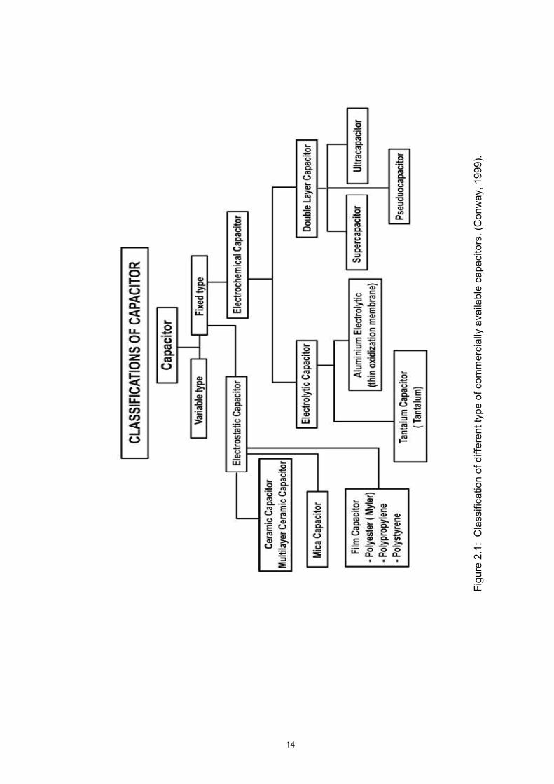
Figure 2.1 shows the classification of different type of commercially available
capacitors. Fixed capacitors have capacitance values that cannot be physically
adjusted. They can be divided into electrostatic and electrochemical categories. In the
latter, electrolytic capacitors use either a solid or liquid electrolyte in their construction.
They have high capacitance values and offer the highest energy densities compared to
the conventional capacitors. These capacitors are inherently polar due to their
construction. A polar capacitor can only handle current flow in only one direction. The
electrochemical double layer capacitors are a new type of capacitors. These are also
known as ultra-capacitors or super-capacitors because their capacitance values can
measure as high as several hundred farads. These capacitors are used in battery-
assisted applications such as cell phones and electric vehicles (Conway, 1999).
14
Figu
re 2
.1:
Cla
ssifi
catio
n of
diff
eren
t typ
e of
com
mer
cial
ly a
vaila
ble
capa
cito
rs. (
Con
way
, 199
9).
15
2.1 Current understanding of Electrochemical capacitors
2.1.1 Basic principle of a capacitor
A capacitor is commonly known as an electrical condenser. The amount of
electricity which a capacitor will hold depends on the electrical pressure or voltage
applied to the capacitor. The plates are charged with equal amounts of positive and
negative electrical charges, respectively. This is a "physical" storage of electricity and
is analogous with the "chemical" storage in a battery. A capacitor is said to be charged
when there are more electron on one conductor plate than on the other. If an electric
potential (voltage) is applied to the capacitor plates, the plates will become charged,
one positively and one negatively. The plate with the larger number of electrons has
the negative polarity. The opposite plate then has the positive polarity. When a
capacitor is charged, the energy is stored in the dielectric material in the form of
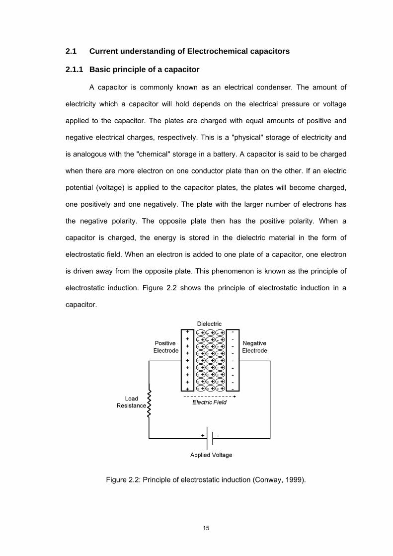
electrostatic field. When an electron is added to one plate of a capacitor, one electron
is driven away from the opposite plate. This phenomenon is known as the principle of
electrostatic induction. Figure 2.2 shows the principle of electrostatic induction in a
capacitor.
Figure 2.2: Principle of electrostatic induction (Conway, 1999).
16
2.1.1.2 Capacitance
Capacitors, regardless of type or kind, are all designated by their electrical size.
In capacitors, this electrical size is designated as capacity. The capacity of an electrical
capacitor is the ratio of the quantity of electricity and the electrical pressure or voltage.
In other words the capacity of a capacitor depends on the amount of electricity it will
hold at a certain electrical pressure or voltage. (Conway, 1999).
This ratio may be expressed as follows:
Q = CV ------- Eq. 2.1
Q = quantity of electricity
C = capacity of the capacitor
V = electrical pressure or voltage
By the same token the capacity may be expressed as follows:
C = Q / V ------- Eq. 2.2
Where the capacity is equal to the quantity of electricity divided by the electrical
pressure or voltage. The capacity of a capacitor is dependent upon the size and
spacing of the conducting plates and the type of insulating or dielectric medium
between the plates. It is known as capacitance.
C = ε A / d ------- Eq. 2.3
C = capacitance in farads, F
ε = dielectric constant
ε = εoεr
ε o is the space permittivity (8.854 x 10 –12 F/m2)
ε r is the relative permittivity
A = area of one plate in square meters, m2
d = distance between plates in meters, m
17
The capacitance is directly proportional to the surface areas of the plates, and
is inversely proportional to the separation between the plates. Capacitance also
depends on the dielectric constant of the substance separating the plates. The
standard unit of capacitance is the farad, abbreviated F. This is a large unit; more
common units are the microfarad, abbreviated μF (1 μF = 10-6 F) and the picofarad,
abbreviated pF (1 pF = 10-12 F). The greater the area for storing charge, and the closer
the separated charges, the greater is the capacitance.
2.1.2 Electrochemical Capacitor
2.1.2.1 The Electrochemical Double Layer Capacitor
As mentioned briefly in the earlier literature review, ELDCs or ECs store
charges in the electrode/ electrolyte interface. High surface area electrodes are used in
electrochemical capacitors resulting in large double layer capacitance, and much of the
storage capacity which is due to the charging/discharging of the double layer. At some
surface oxidation/reduction also occurs, but in contrast to reactions occurring in
batteries, this is limited to a monolayer or two on the electrode surfaces. Consequently,
the device behaves more like a capacitor than a battery. EDLC is also called
"supercapacitor" (SCs) and "ultracapacitor" depending upon the materials and
electrodes used. EDLC typically have much larger power density but much smaller
energy density than batteries. Charge is stored electrostatically in polarized liquid
layers between an ionically conducting electrolyte and an electrochemically-conducting
electrode. This energy storage mechanism is either based on capacitive (non-faradic)
or pseudocapacitive (faradic) which will be discussed later (Conway, 1999).
.
18
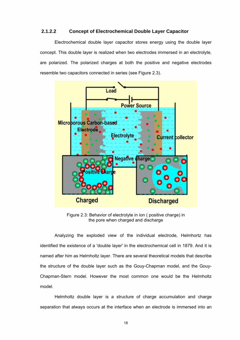
2.1.2.2 Concept of Electrochemical Double Layer Capacitor
Electrochemical double layer capacitor stores energy using the double layer
concept. This double layer is realized when two electrodes immersed in an electrolyte,
are polarized. The polarized charges at both the positive and negative electrodes
resemble two capacitors connected in series (see Figure 2.3).
Figure 2.3: Behavior of electrolyte in ion ( positive charge) in the pore when charged and discharge
Analyzing the exploded view of the individual electrode, Helmhortz has
identified the existence of a 'double layer' in the electrochemical cell in 1879. And it is
named after him as Helmholtz layer. There are several theoretical models that describe
the structure of the double layer such as the Gouy-Chapman model, and the Gouy-
Chapman-Stern model. However the most common one would be the Helmholtz
model.
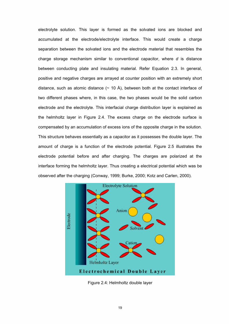
Helmholtz double layer is a structure of charge accumulation and charge
separation that always occurs at the interface when an electrode is immersed into an
19
electrolyte solution. This layer is formed as the solvated ions are blocked and
accumulated at the electrode/electrolyte interface. This would create a charge
separation between the solvated ions and the electrode material that resembles the
charge storage mechanism similar to conventional capacitor, where d is distance
between conducting plate and insulating material. Refer Equation 2.3. In general,
positive and negative charges are arrayed at counter position with an extremely short
distance, such as atomic distance (~ 10 Å), between both at the contact interface of
two different phases where, in this case, the two phases would be the solid carbon
electrode and the electrolyte. This interfacial charge distribution layer is explained as
the helmholtz layer in Figure 2.4. The excess charge on the electrode surface is
compensated by an accumulation of excess ions of the opposite charge in the solution.
This structure behaves essentially as a capacitor as it possesses the double layer. The
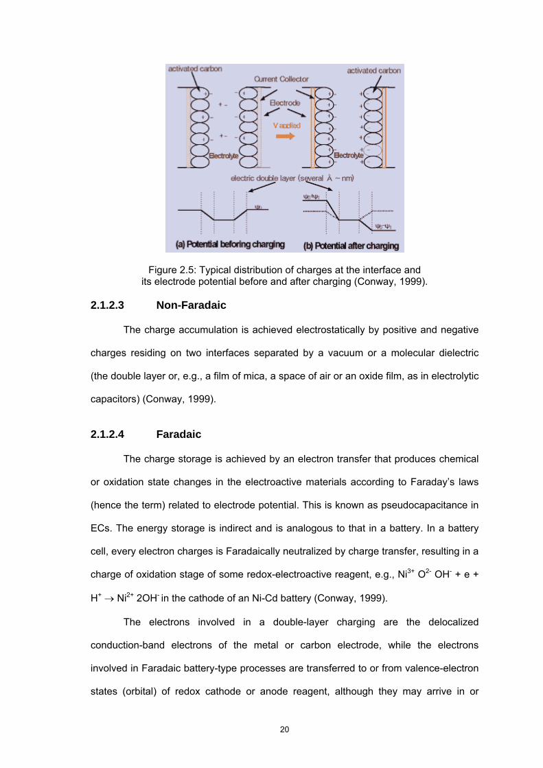
amount of charge is a function of the electrode potential. Figure 2.5 illustrates the
electrode potential before and after charging. The charges are polarized at the
interface forming the helmholtz layer. Thus creating a electrical potential which was be
observed after the charging (Conway, 1999; Burke, 2000; Kotz and Carlen, 2000).
Figure 2.4: Helmholtz double layer
20
Figure 2.5: Typical distribution of charges at the interface and its electrode potential before and after charging (Conway, 1999).
2.1.2.3 Non-Faradaic
The charge accumulation is achieved electrostatically by positive and negative
charges residing on two interfaces separated by a vacuum or a molecular dielectric
(the double layer or, e.g., a film of mica, a space of air or an oxide film, as in electrolytic
capacitors) (Conway, 1999).
2.1.2.4 Faradaic
The charge storage is achieved by an electron transfer that produces chemical
or oxidation state changes in the electroactive materials according to Faraday’s laws
(hence the term) related to electrode potential. This is known as pseudocapacitance in
ECs. The energy storage is indirect and is analogous to that in a battery. In a battery
cell, every electron charges is Faradaically neutralized by charge transfer, resulting in a
charge of oxidation stage of some redox-electroactive reagent, e.g., Ni3+ O2- OH- + e +
H+ → Ni2+ 2OH- in the cathode of an Ni-Cd battery (Conway, 1999).
The electrons involved in a double-layer charging are the delocalized
conduction-band electrons of the metal or carbon electrode, while the electrons
involved in Faradaic battery-type processes are transferred to or from valence-electron
states (orbital) of redox cathode or anode reagent, although they may arrive in or
21
depart from the conduction-band states of the electronically conducting support
material. In certain cases, the faradaically reactive battery material itself is metallically
conducting (e.g., PbO2, some sulfides, RuO2 (Trasatti and Buzzanca, 1971) or else is a
well-conducting semiconductor and a productor, e.g., NiOOH (Oliva et al, 1982).
2.1.2.5 Characteristics of Electrochemical Double layer Capacitor
Some of the main characteristic of EDLC (Conway, 1999);
It employs carbon or metal oxides as the material for the electrodes
Its capacitance values can be measured as high as several hundreds of Farads
(F)
Fast charge time up to a few seconds
High specific power density compared to batteries ( at least two order of
degree) but specific energy density is one order less than batteries.
It can be charged to any voltage within its voltage rating.
Stores much more energy than a conventional capacitor of similar size.
Able to deliver frequent pulses of energy without any detrimental effects unlike
batteries which experience reduced life if exposed to frequent high power
pulses
Can be charged extremely fast while batteries are damaged by fast charging.
Can be cycled hundreds of thousands of times unlike batteries which are
cyclable only up to few hundred cycles.
No charge circuit (Self charge)
No explosion risk
It requires no maintenance and is robust to environmental extremities such a
arctic temperatures.
Wide temperature range ( operation )
Pollution free
No liquid leak (if properly sealed)
22
2.2 Classifications of Electrochemical capacitors
2.2.1 Supercapacitor , Pseudocapacitor, Hybrid Capacitor
As mentioned earlier, ultracapacitors, supercapacitors, powercapacitor and
pseudocapacitors are also known as other names for double layer capacitor which are
established colloquial names. They are named duly by the cell performance. The term
“super” capacitor is most commonly used for carbon based double layer capacitors
because of its high capacitance value. On the other hand, double layer capacitors with
metal oxide electrodes are known as hybrid electrochemical capacitors / ultracapacitors
for their very low equivalent series resistance value (ESR). It is also known as
pseudocapacitor if it exhibits pseudocapacitance behaviour ( faradaic reaction like in
battery). Figure 2.1 is the summary of classification of capacitor.
2.2.2 Pseudocapacitance
There are two basic reactions, which lead to electrochemical cell. Both occur at
the interface between a conductor and an electrolyte and both benefit from very high
specific surface areas at the electrode. Surface areas around 2,000 m2/g are
commonly available for carbons while 140 m2/g commonly available for ruthenium
oxide (metal oxide). The first mechanism commonly referred to as charge separation,
which is well documented as a non-Faradic mechanism and is the basis for EDLC. The
charges are basically blocked at the electrode/electrolyte interface, preventing the
charges to diffuse. The second reaction commonly referred to as an oxidation-
reduction reaction (redox) due to faradic mechanism, which is the basis for
pseudocapacitance. In here, the charges are partially blocked where some charges
diffuse into the electrode material and intercalate. The term pseudocapacitor is
commonly used to explain the pseudocapacitance behaviour of such double layer
capacitors. Carbon is an example of a charge separation of non-Faradic electrode
23
material and ruthenium oxide is an example of faradic electrode material (Conway,
1999).
Although, pseudocapacitor has electrochemical reaction similar to battery (the
faradic mechanism), the distinction between a battery and an electrochemical double
layer capacitor is not explicit. A battery relies on electrochemical reactions that involve
active materials in the electrode, where the charges are not blocked, diffuse into the
material and intercalate. In this case, active means that the materials participate in the
reaction, and a transfer of electrons between the active material and ionic species in
solution occurs across the solid/liquid interface. On the other hand, in an "ideal"
electrochemical capacitor that utilizes carbon or metal oxides, the electrodes play
passive role. That is, the electrode surface only participates by serving as sites for
charged species to accumulate and no electron transfer occurs across the
solid/liquidinterface. In a "practical" electrochemical capacitor there may occur some
surfaceoxidation/reduction on the electrodes, that is, it operates partly as a capacitor
and partly as a battery. Of course, this phenomenon is depends on the material
properties. So, in order to characterize a double layer capacitor, one has to investigate
the above behavior (Conway, 1999).
The metal oxide technology of the pseudocapacitor utilizes an electrochemical
reaction similar to battery technology for energy storage, thus improving potential
energy density. Since the pseudocapacitor uses a dense metal oxide as the electrode
material, the load of the oxide is three times that of the EDLC for the same-coated
area. With this advantage, pseudocapacitor cell needs to be only 60% in volume as
compared to an EDLC of the same capacitance. Conversely, it also means the
pseudocapacitor holds 80% more energy than the equivalent-size EDLC. Finally, the
pseudocapacitor uses the same manufacturing processes and facilities as EDLC
production.
24
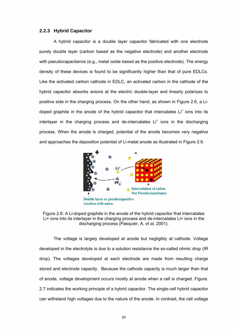
2.2.3 Hybrid Capacitor
A hybrid capacitor is a double layer capacitor fabricated with one electrode
purely double layer (carbon based as the negative electrode) and another electrode
with pseudocapacitance (e.g., metal oxide based as the positive electrode). The energy
density of these devices is found to be significantly higher than that of pure EDLCs.
Like the activated carbon cathode in EDLC, an activated carbon in the cathode of the
hybrid capacitor absorbs anions at the electric double-layer and linearly polarizes to
positive side in the charging process. On the other hand, as shown in Figure 2.6, a Li-
doped graphite in the anode of the hybrid capacitor that intercalates Li+ ions into its
interlayer in the charging process and de-intercalates Li+ ions in the discharging
process. When the anode is charged, potential of the anode becomes very negative
and approaches the deposition potential of Li-metal anode as illustrated in Figure 2.6.
Figure 2.6: A Li-doped graphite in the anode of the hybrid capacitor that intercalates Li+ ions into its interlayer in the charging process and de-intercalates Li+ ions in the
discharging process (Pasquier, A. et al, 2001).
The voltage is largely developed at anode but negligibly at cathode. Voltage
developed in the electrolyte is due to a solution resistance the so-called ohmic drop (IR
drop). The voltages developed at each electrode are made from resulting charge
stored and electrode capacity. Because the cathode capacity is much larger than that
of anode, voltage development occurs mostly at anode when a cell is charged. Figure.
2.7 indicates the working principle of a hybrid capacitor. The single-cell hybrid capacitor
can withstand high voltages due to the nature of the anode. In contrast, the cell voltage