Comparison of Maglev and wheel-rail Track Design ...Comparison of Maglev and wheel-rail Track Design...
10
Comparison of Maglev and wheel-rail Track Design Parameters with Focus on Routing, Operation, and Cost-efficiency Martin Retzmann International Maglevboard e.V., Guido-Schneble-Str. 32, 80680 Munich, Germany, [email protected] ABSTRACT: Current discussions on the implementation of maglev projects are mainly focusing on questions of technical feasibility, financing, cost efficiency, and energy consumption. In doing so, aspects of favorable and sustainable routing in both urban and rural areas are often falling behind the scenes. However, maglev systems are having some fundamental advantages in terms of routing and track design compared to wheel/rail systems. This leads to a lower need in capital expenditure in planning and construction phases as well as subsequent lower operation costs. The paper is going to focus on these aspects and describing its effects on routing, operation, and cost-efficiency. 1 INTRODUCTION Civil engineering structures such as bridges, tunnels, and earthworks essentially determine the investment costs and maintenance expenses for the infrastructure of land transport systems. Requirements for huge civil engineering structures of a transport system will be shorten the best by flexible track design parameters. This will result into a better alignment to existing terrain. Apart from cross- sectional width also horizontal and vertical parameters are essential for track routing. These are mainly the smallest horizontal radius, the largest possible superelevation, and the maximal longitudinal gradient with necessary transition radii of crowns and troughs. The first part of the paper will show the main track design parameters of high-speed railroads on the example of Deutsche Bahn AG compared with those of the Transrapid maglev. The impact on the horizontal and vertical routing are presented by means of theoretical examples. Consequences on routing and operation of the respective high-speed railroad systems are illustrated by a case study of the medium mountain range traversing between Dresden, Germany, and Prague, Czech Republic. For the same design speed the case study shows significant technical and operational benefits for the maglev high-speed system. Thus, the total tunnel length is four times shorter and the total length of viaducts in half shorter than of the high-speed railroad. The second part of the paper will discuss on a comparison of main track design parameters of urban rapid transit wheel/rail systems with those of urban maglev systems such as Linimo. The impact on the horizontal and vertical routing are again presented by means of an example. Consequences on routing and operation of the respective urban transport systems are illustrated by an appropriate and typical in the urban environment encountered case. The paper will finish by rounding both parts to conclusions on the influence of routing on the expected maintenance costs. 2 THE AIM OF THE INTERNATIONAL MAGLEVBOARD AND ITS RELATION TO THIS PAPER Maglev systems represent a revolutionary transport innovation. At the same time, they can also function as a technology development platform (e.g., superconductors, new materials). They can, in certain cases, bring positive economic benefits through the optimization of spatial networking, travel time reduction and resource efficiency. A meaningful use of the technology also brings collective social advantages as well as a good image and prestige. Maglev should be promoted in places and situations where its use is meaningful, based on an The 21st International Conference on Magnetically Levitated Systems and Linear Drives, October 10-13, 2011, Daejeon, Korea
Transcript of Comparison of Maglev and wheel-rail Track Design ...Comparison of Maglev and wheel-rail Track Design...
Comparison of Maglev and wheel-rail Track Design Parameters with Focus on Routing, Operation, and Cost-efficiency
Martin Retzmann International Maglevboard e.V., Guido-Schneble-Str. 32, 80680 Munich, Germany, [email protected] ABSTRACT: Current discussions on the implementation of maglev projects are mainly focusing on questions of technical feasibility, financing, cost efficiency, and energy consumption. In doing so, aspects of favorable and sustainable routing in both urban and rural areas are often falling behind the scenes. However, maglev systems are having some fundamental advantages in terms of routing and track design compared to wheel/rail systems. This leads to a lower need in capital expenditure in planning and construction phases as well as subsequent lower operation costs. The paper is going to focus on these aspects and describing its effects on routing, operation, and cost-efficiency.
1 INTRODUCTION
Civil engineering structures such as bridges, tunnels, and earthworks essentially determine the investment costs and maintenance expenses for the infrastructure of land transport systems. Requirements for huge civil engineering structures of a transport system will be shorten the best by flexible track design parameters. This will result into a better alignment to existing terrain. Apart from cross-sectional width also horizontal and vertical parameters are essential for track routing. These are mainly the smallest horizontal radius, the largest possible superelevation, and the maximal longitudinal gradient with necessary transition radii of crowns and troughs.
The first part of the paper will show the main track design parameters of high-speed railroads on the example of Deutsche Bahn AG compared with those of the Transrapid maglev. The impact on the horizontal and vertical routing are presented by means of theoretical examples. Consequences on routing and operation of the respective high-speed railroad systems are illustrated by a case study of the medium mountain range traversing between Dresden, Germany, and Prague, Czech Republic. For the same design speed the case study shows significant technical and operational benefits for the maglev high-speed system. Thus, the total tunnel length is
four times shorter and the total length of viaducts in half shorter than of the high-speed railroad. The second part of the paper will discuss on a comparison of main track design parameters of urban rapid transit wheel/rail systems with those of urban maglev systems such as Linimo. The impact on the horizontal and vertical routing are again presented by means of an example. Consequences on routing and operation of the respective urban transport systems are illustrated by an appropriate and typical in the urban environment encountered case. The paper will finish by rounding both parts to conclusions on the influence of routing on the expected maintenance costs.
2 THE AIM OF THE INTERNATIONAL MAGLEVBOARD AND ITS RELATION TO THIS PAPER
Maglev systems represent a revolutionary transport innovation. At the same time, they can also function as a technology development platform (e.g., superconductors, new materials). They can, in certain cases, bring positive economic benefits through the optimization of spatial networking, travel time reduction and resource efficiency. A meaningful use of the technology also brings collective social advantages as well as a good image and prestige.
Maglev should be promoted in places and situations where its use is meaningful, based on an
The 21st International Conference on Magnetically Levitated Systems and Linear Drives, October 10-13, 2011, Daejeon, Korea
objective weighing of the available facts. Especially important evaluation criteria for all systems, in addition to their technical and operational benefits, are their long-term economic effects and life-cycle costs.
The International Maglevboard e.V., or "The international Society for Maglev Transportation", is an international non-profit organization. It is made up of internationally known transport scientists, engineers, experts as well as members of citizens' movements.
The International Maglevboard is oriented to the public interest, works independently and, as a basic tenet, does not represent any commercial interests. It is oriented toward interdisciplinary and scientifically based support of long-term social well-being, especially in relation to sustainable mobility. One focus of our attention concerns the prospects and limitations of magnetic levitation transport technologies.
3 COMPARISON BETWEEN HIGH-SPEED RAILROAD AND MAGLEV
3.1 Basic Principles of Route Alignment The route alignment of rail guided transport
systems is traditionally based on first horizontal and second vertical routing. This principle does not cause any big trouble in matters of driving dynamics for design speeds of conventional wheel/rail systems for speeds of up to 160 km/h. A straight line in both horizontal and vertical alignment is the most preferred alignment element. The required size of the circular arc radius on horizontal alignment is determined by the intended operating speed (design speed), the maximum lateral inclination of the guideway and a possible unbalanced superelevation. Against them, the maximum allowable longitudinal gradient is primarily determined by the propulsion system. The trains are possibly to be transported on a slope without any major loss of speed. The determining variable of vertical fillets is the permissible factor of normal acceleration.
3.2 Acceleration and Deceleration Parameters for High-speed Systems
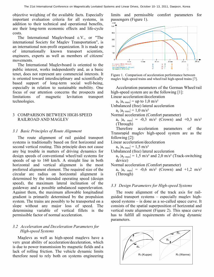
Maglevs as well as high-speed maglevs have a very great ability of acceleration/deceleration, which is due to power transmission by magnetic fields and a lack of rolling friction. The vehicle dynamic limits therefore need to rely both on systems engineering
limits and permissible comfort parameters for passengers (Figure 1).
Figure 1. Comparison of acceleration performance between maglev high-speed trains and wheel/rail high-speed trains [7].
Acceleration parameters of the German Wheel/rail
high-speed system are as the following [1]: Linear acceleration/deceleration
ax |ax max| = up to 1,0 m/s² Unbalanced (free) lateral acceleration
ay |ay max| = 1,0 m/s² Normal acceleration (Comfort parameter)
az |az max| = -0,3 m/s² (Crown) and +0,3 m/s² (Through) Therefore acceleration parameters of the
Transrapid maglev high-speed system are as the following [2]: Linear acceleration/deceleration
ax |ax max| = 1,5 m/s² Unbalanced (free) lateral acceleration
ay |ay max| = 1,5 m/s² and 2,0 m/s² (Track-switching device)
Normal acceleration (Comfort parameter) az |az max| = -0,6 m/s² (Crown) and +1,2 m/s² (Through)
3.3 Design Parameters for High-speed Systems The route alignment of the track axis for rail-
guided transport systems – especially maglev high-speed systems – is done as a so-called space curve. It consists of the spatial superposition of horizontal and vertical route alignment (Figure 2). This space curve has to fulfill all requirements of driving dynamic parameters.
Rh
Rv Rv
Rh
Rh (Wanne)Rh (Kuppe)
The 21st International Conference on Magnetically Levitated Systems and Linear Drives, October 10-13, 2011, Daejeon, Korea
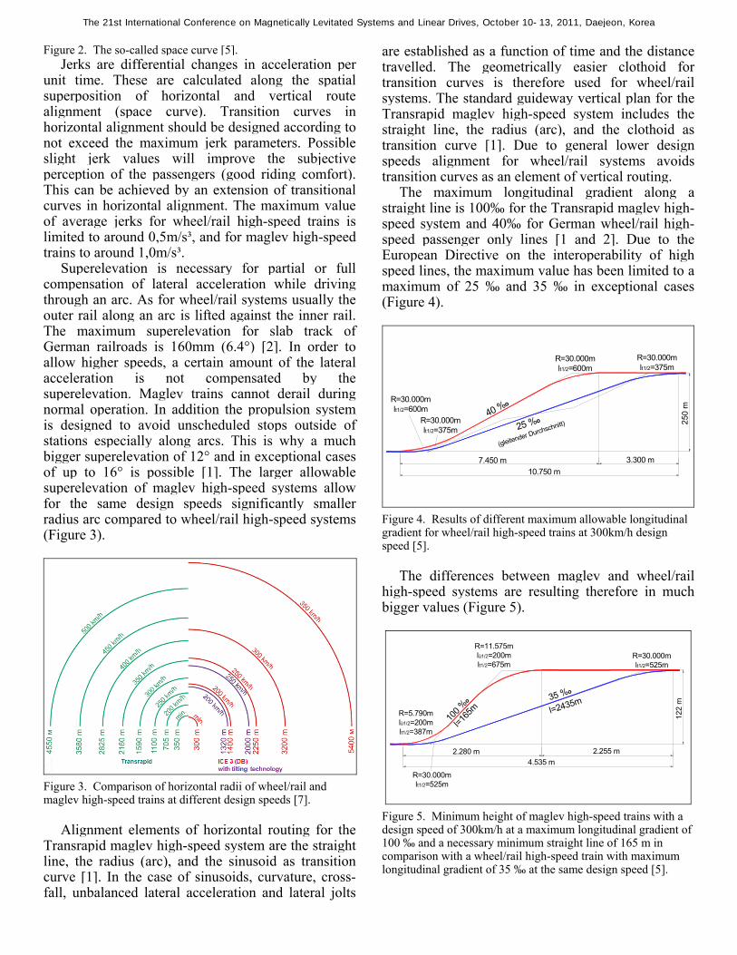
Figure 2. The so-called space curve [5]. Jerks are differential changes in acceleration per
unit time. These are calculated along the spatial superposition of horizontal and vertical route alignment (space curve). Transition curves in horizontal alignment should be designed according to not exceed the maximum jerk parameters. Possible slight jerk values will improve the subjective perception of the passengers (good riding comfort). This can be achieved by an extension of transitional curves in horizontal alignment. The maximum value of average jerks for wheel/rail high-speed trains is limited to around 0,5m/s³, and for maglev high-speed trains to around 1,0m/s³.
Superelevation is necessary for partial or full compensation of lateral acceleration while driving through an arc. As for wheel/rail systems usually the outer rail along an arc is lifted against the inner rail. The maximum superelevation for slab track of German railroads is 160mm (6.4°) [2]. In order to allow higher speeds, a certain amount of the lateral acceleration is not compensated by the superelevation. Maglev trains cannot derail during normal operation. In addition the propulsion system is designed to avoid unscheduled stops outside of stations especially along arcs. This is why a much bigger superelevation of 12° and in exceptional cases of up to 16° is possible [1]. The larger allowable superelevation of maglev high-speed systems allow for the same design speeds significantly smaller radius arc compared to wheel/rail high-speed systems (Figure 3).
Figure 3. Comparison of horizontal radii of wheel/rail and maglev high-speed trains at different design speeds [7].
Alignment elements of horizontal routing for the
Transrapid maglev high-speed system are the straight line, the radius (arc), and the sinusoid as transition curve [1]. In the case of sinusoids, curvature, cross-fall, unbalanced lateral acceleration and lateral jolts
are established as a function of time and the distance travelled. The geometrically easier clothoid for transition curves is therefore used for wheel/rail systems. The standard guideway vertical plan for the Transrapid maglev high-speed system includes the straight line, the radius (arc), and the clothoid as transition curve [1]. Due to general lower design speeds alignment for wheel/rail systems avoids transition curves as an element of vertical routing.
The maximum longitudinal gradient along a straight line is 100‰ for the Transrapid maglev high-speed system and 40‰ for German wheel/rail high-speed passenger only lines [1 and 2]. Due to the European Directive on the interoperability of high speed lines, the maximum value has been limited to a maximum of 25 ‰ and 35 ‰ in exceptional cases (Figure 4).
R=30.000m lt1/2=600m
250
m
40 %o
25 %o
(gleitender Durchschnitt)
10.750 m7.450 m 3.300 m
R=30.000m lt1/2=600m
R=30.000m lt1/2=375m
R=30.000m lt1/2=375m
Figure 4. Results of different maximum allowable longitudinal gradient for wheel/rail high-speed trains at 300km/h design speed [5].
The differences between maglev and wheel/rail
high-speed systems are resulting therefore in much bigger values (Figure 5).
122
m35 %o
4.535 m2.280 m 2.255 m
R=5.790m lü1/2=200m lt1/2=387m
R=30.000m lt1/2=525m
R=11.575m lü1/2=200m lt1/2=675m
100 %
o
l=165
m
R=30.000m lt1/2=525m
l=2435m
Figure 5. Minimum height of maglev high-speed trains with a design speed of 300km/h at a maximum longitudinal gradient of 100 ‰ and a necessary minimum straight line of 165 m in comparison with a wheel/rail high-speed train with maximum longitudinal gradient of 35 ‰ at the same design speed [5].
The 21st International Conference on Magnetically Levitated Systems and Linear Drives, October 10-13, 2011, Daejeon, Korea
3.4 The Case Study of a proposed high-speed line
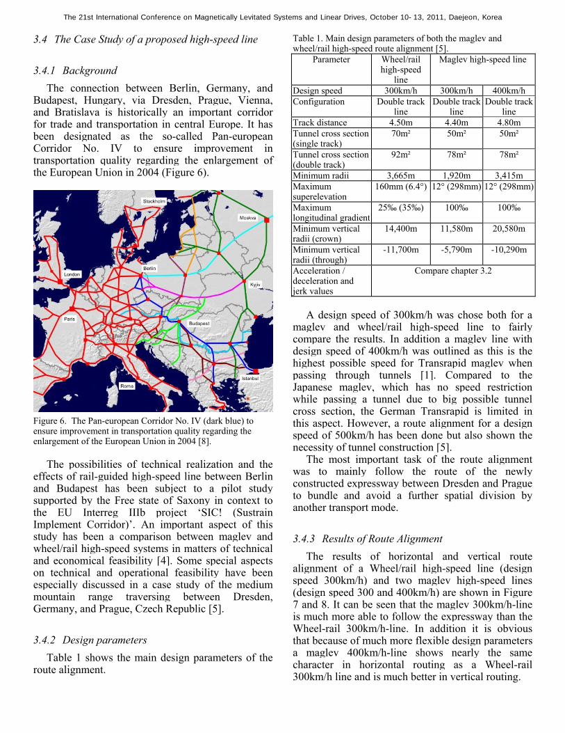
3.4.1 Background The connection between Berlin, Germany, and
Budapest, Hungary, via Dresden, Prague, Vienna, and Bratislava is historically an important corridor for trade and transportation in central Europe. It has been designated as the so-called Pan-european Corridor No. IV to ensure improvement in transportation quality regarding the enlargement of the European Union in 2004 (Figure 6).
Figure 6. The Pan-european Corridor No. IV (dark blue) to ensure improvement in transportation quality regarding the enlargement of the European Union in 2004 [8].
The possibilities of technical realization and the
effects of rail-guided high-speed line between Berlin and Budapest has been subject to a pilot study supported by the Free state of Saxony in context to the EU Interreg IIIb project ‘SIC! (Sustrain Implement Corridor)’. An important aspect of this study has been a comparison between maglev and wheel/rail high-speed systems in matters of technical and economical feasibility [4]. Some special aspects on technical and operational feasibility have been especially discussed in a case study of the medium mountain range traversing between Dresden, Germany, and Prague, Czech Republic [5].
3.4.2 Design parameters Table 1 shows the main design parameters of the
route alignment.
Table 1. Main design parameters of both the maglev and wheel/rail high-speed route alignment [5].
Parameter Wheel/rail high-speed
line
Maglev high-speed line
Design speed 300km/h 300km/h 400km/hConfiguration Double track
line Double track
lineDouble track
lineTrack distance 4.50m 4.40m 4.80mTunnel cross section(single track)
70m² 50m² 50m²
Tunnel cross section (double track)
92m² 78m² 78m²
Minimum radii 3,665m 1,920m 3,415mMaximum superelevation
160mm (6.4°) 12° (298mm) 12° (298mm)
Maximum longitudinal gradient
25‰ (35‰) 100‰ 100‰
Minimum vertical radii (crown)
14,400m 11,580m 20,580m
Minimum vertical radii (through)
-11,700m -5,790m -10,290m
Acceleration / deceleration and jerk values
Compare chapter 3.2
A design speed of 300km/h was chose both for a
maglev and wheel/rail high-speed line to fairly compare the results. In addition a maglev line with design speed of 400km/h was outlined as this is the highest possible speed for Transrapid maglev when passing through tunnels [1]. Compared to the Japanese maglev, which has no speed restriction while passing a tunnel due to big possible tunnel cross section, the German Transrapid is limited in this aspect. However, a route alignment for a design speed of 500km/h has been done but also shown the necessity of tunnel construction [5].
The most important task of the route alignment was to mainly follow the route of the newly constructed expressway between Dresden and Prague to bundle and avoid a further spatial division by another transport mode.
3.4.3 Results of Route Alignment The results of horizontal and vertical route
alignment of a Wheel/rail high-speed line (design speed 300km/h) and two maglev high-speed lines (design speed 300 and 400km/h) are shown in Figure 7 and 8. It can be seen that the maglev 300km/h-line is much more able to follow the expressway than the Wheel-rail 300km/h-line. In addition it is obvious that because of much more flexible design parameters a maglev 400km/h-line shows nearly the same character in horizontal routing as a Wheel-rail 300km/h line and is much better in vertical routing.
The 21st International Conference on Magnetically Levitated Systems and Linear Drives, October 10-13, 2011, Daejeon, Korea
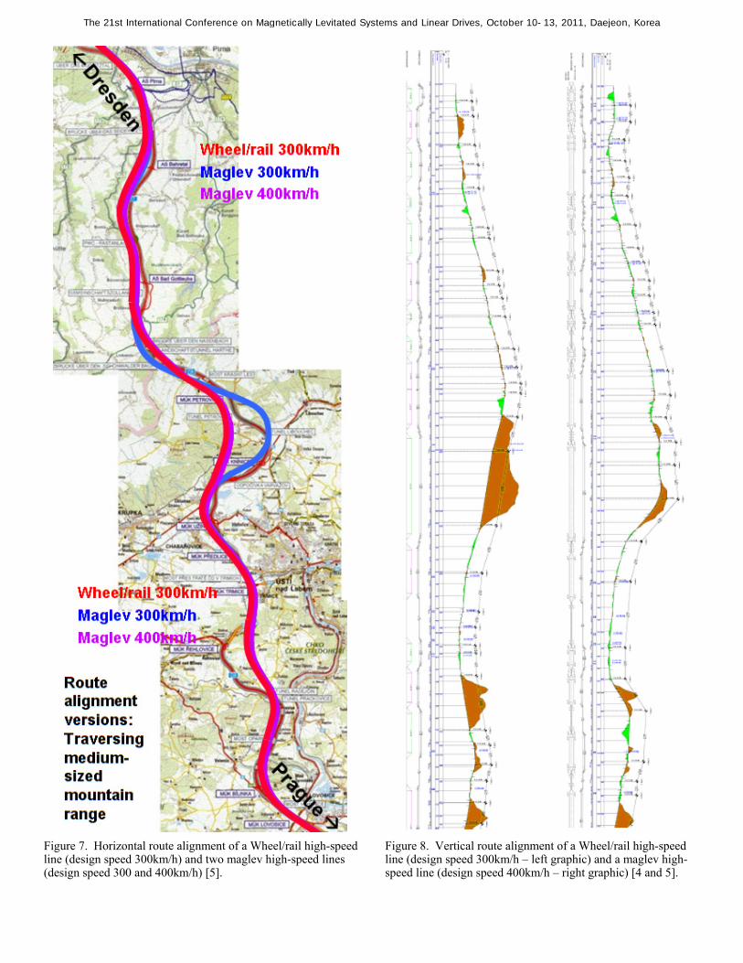
Figure 7. Horizontal route alignment of a Wheel/rail high-speed line (design speed 300km/h) and two maglev high-speed lines (design speed 300 and 400km/h) [5].
Figure 8. Vertical route alignment of a Wheel/rail high-speed line (design speed 300km/h – left graphic) and a maglev high-speed line (design speed 400km/h – right graphic) [4 and 5].
The 21st International Conference on Magnetically Levitated Systems and Linear Drives, October 10-13, 2011, Daejeon, Korea
All lines lead from a height of around 120m up to more than 500m above sea-level. Steep and long grades can be seen on all lines. The gradient of the maglev line for a design speed of 400km/h contains even a possible 100‰ grade due to the high mountains. This shows that the flexible alignment of Transrapid maglev is very helpful even in medium-sized mountain ranges to avoid long tunnels or bridges.
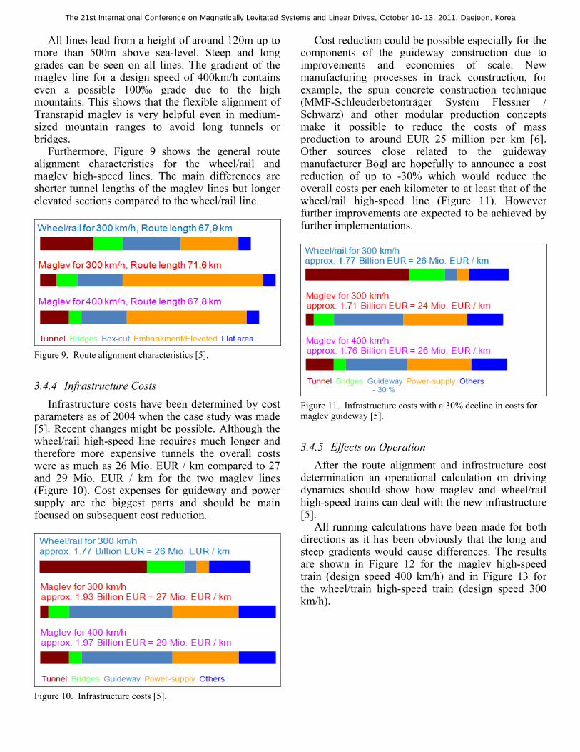
Furthermore, Figure 9 shows the general route alignment characteristics for the wheel/rail and maglev high-speed lines. The main differences are shorter tunnel lengths of the maglev lines but longer elevated sections compared to the wheel/rail line.
Figure 9. Route alignment characteristics [5].
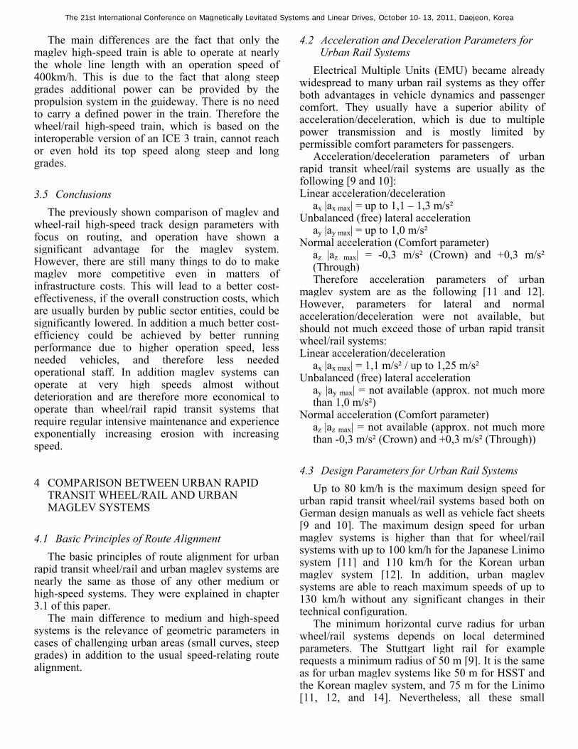
3.4.4 Infrastructure Costs Infrastructure costs have been determined by cost
parameters as of 2004 when the case study was made [5]. Recent changes might be possible. Although the wheel/rail high-speed line requires much longer and therefore more expensive tunnels the overall costs were as much as 26 Mio. EUR / km compared to 27 and 29 Mio. EUR / km for the two maglev lines (Figure 10). Cost expenses for guideway and power supply are the biggest parts and should be main focused on subsequent cost reduction.
Figure 10. Infrastructure costs [5].
Cost reduction could be possible especially for the components of the guideway construction due to improvements and economies of scale. New manufacturing processes in track construction, for example, the spun concrete construction technique (MMF-Schleuderbetonträger System Flessner / Schwarz) and other modular production concepts make it possible to reduce the costs of mass production to around EUR 25 million per km [6]. Other sources close related to the guideway manufacturer Bögl are hopefully to announce a cost reduction of up to -30% which would reduce the overall costs per each kilometer to at least that of the wheel/rail high-speed line (Figure 11). However further improvements are expected to be achieved by further implementations.
Figure 11. Infrastructure costs with a 30% decline in costs for maglev guideway [5].
3.4.5 Effects on Operation After the route alignment and infrastructure cost
determination an operational calculation on driving dynamics should show how maglev and wheel/rail high-speed trains can deal with the new infrastructure [5].
All running calculations have been made for both directions as it has been obviously that the long and steep gradients would cause differences. The results are shown in Figure 12 for the maglev high-speed train (design speed 400 km/h) and in Figure 13 for the wheel/train high-speed train (design speed 300 km/h).
The 21st International Conference on Magnetically Levitated Systems and Linear Drives, October 10-13, 2011, Daejeon, Korea

Figure 12. Running calculation for a maglev high-speed train (design speed 400km/h) southbound (left graphic) and northbound (right graphic) [5].
Figure 13. Running calculation for a wheel/rail high-speed train (design speed 300km/h) southbound (graphic at the top) and northbound (graphic at the bottom) [5].
The 21st International Conference on Magnetically Levitated Systems and Linear Drives, October 10-13, 2011, Daejeon, Korea
The main differences are the fact that only the maglev high-speed train is able to operate at nearly the whole line length with an operation speed of 400km/h. This is due to the fact that along steep grades additional power can be provided by the propulsion system in the guideway. There is no need to carry a defined power in the train. Therefore the wheel/rail high-speed train, which is based on the interoperable version of an ICE 3 train, cannot reach or even hold its top speed along steep and long grades.
3.5 Conclusions The previously shown comparison of maglev and
wheel-rail high-speed track design parameters with focus on routing, and operation have shown a significant advantage for the maglev system. However, there are still many things to do to make maglev more competitive even in matters of infrastructure costs. This will lead to a better cost-effectiveness, if the overall construction costs, which are usually burden by public sector entities, could be significantly lowered. In addition a much better cost-efficiency could be achieved by better running performance due to higher operation speed, less needed vehicles, and therefore less needed operational staff. In addition maglev systems can operate at very high speeds almost without deterioration and are therefore more economical to operate than wheel/rail rapid transit systems that require regular intensive maintenance and experience exponentially increasing erosion with increasing speed.
4 COMPARISON BETWEEN URBAN RAPID TRANSIT WHEEL/RAIL AND URBAN MAGLEV SYSTEMS
4.1 Basic Principles of Route Alignment The basic principles of route alignment for urban
rapid transit wheel/rail and urban maglev systems are nearly the same as those of any other medium or high-speed systems. They were explained in chapter 3.1 of this paper.
The main difference to medium and high-speed systems is the relevance of geometric parameters in cases of challenging urban areas (small curves, steep grades) in addition to the usual speed-relating route alignment.
4.2 Acceleration and Deceleration Parameters for Urban Rail Systems
Electrical Multiple Units (EMU) became already widespread to many urban rail systems as they offer both advantages in vehicle dynamics and passenger comfort. They usually have a superior ability of acceleration/deceleration, which is due to multiple power transmission and is mostly limited by permissible comfort parameters for passengers.
Acceleration/deceleration parameters of urban rapid transit wheel/rail systems are usually as the following [9 and 10]: Linear acceleration/deceleration
ax |ax max| = up to 1,1 – 1,3 m/s² Unbalanced (free) lateral acceleration
ay |ay max| = up to 1,0 m/s² Normal acceleration (Comfort parameter)
az |az max| = -0,3 m/s² (Crown) and +0,3 m/s² (Through) Therefore acceleration parameters of urban
maglev system are as the following [11 and 12]. However, parameters for lateral and normal acceleration/deceleration were not available, but should not much exceed those of urban rapid transit wheel/rail systems: Linear acceleration/deceleration
ax |ax max| = 1,1 m/s² / up to 1,25 m/s² Unbalanced (free) lateral acceleration
ay |ay max| = not available (approx. not much more than 1,0 m/s²)
Normal acceleration (Comfort parameter) az |az max| = not available (approx. not much more than -0,3 m/s² (Crown) and +0,3 m/s² (Through))
4.3 Design Parameters for Urban Rail Systems Up to 80 km/h is the maximum design speed for
urban rapid transit wheel/rail systems based both on German design manuals as well as vehicle fact sheets [9 and 10]. The maximum design speed for urban maglev systems is higher than that for wheel/rail systems with up to 100 km/h for the Japanese Linimo system [11] and 110 km/h for the Korean urban maglev system [12]. In addition, urban maglev systems are able to reach maximum speeds of up to 130 km/h without any significant changes in their technical configuration.
The minimum horizontal curve radius for urban wheel/rail systems depends on local determined parameters. The Stuttgart light rail for example requests a minimum radius of 50 m [9]. It is the same as for urban maglev systems like 50 m for HSST and the Korean maglev system, and 75 m for the Linimo [11, 12, and 14]. Nevertheless, all these small
The 21st International Conference on Magnetically Levitated Systems and Linear Drives, October 10-13, 2011, Daejeon, Korea
horizontal radii require a relative low speed during operation.
The maximum superelevation for slab track of standard gauge urban wheel/rail systems can be the same as for high-speed systems of up to 160mm (6.4°). However, the exact height of superelevation depends on local parameters such as minimum radii, maximum design speed, and vehicle design (bogies etc.). The maximum superelevation of urban maglev systems is 8° for HSST (High speed surface transport) and 6° for the Linimo system, and therefore not much higher than for urban wheel/rail systems [11, 13, and 14].
The maximum longitudinal gradient along a straight line is both 70‰ for the HSST and Korean urban maglev system, 60‰ for the Linimo urban maglev system, and usually up to 40‰ for urban wheel/rail systems [10, 13, and 14]. However, in very challenging urban areas some maglev systems like HSST can climb maximum gradients of up to 100‰ at a reduced speed of around 45 km/h [14]. Therefore, some specially designed urban wheel/rail systems (extended engine power and strong brakes) like the Stuttgart light rail can deal with maximum gradients of up to 90‰ at a reduced speed [9].
The minimum vertical curve radius for urban wheel/rail systems depends usually on the vehicle design characteristic. A minimum vertical radius of 700 m is shown for the HSST urban maglev system [13] and is therefore around the same as for urban wheel/rail systems.
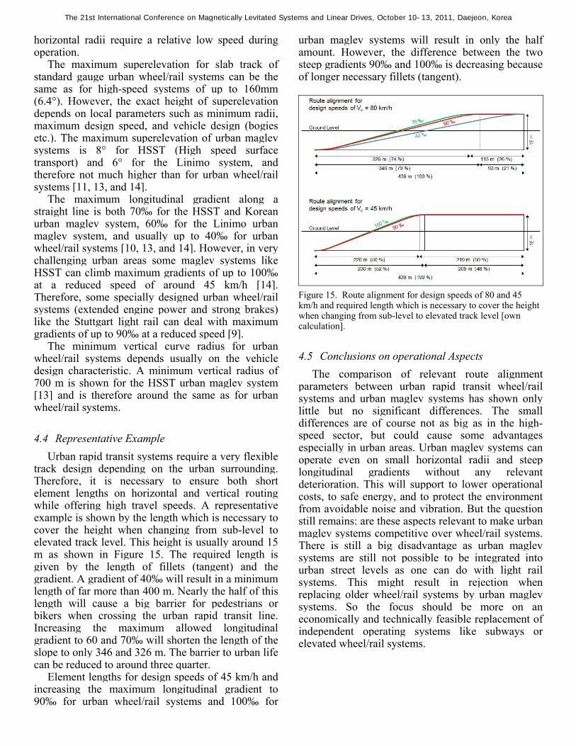
4.4 Representative Example Urban rapid transit systems require a very flexible
track design depending on the urban surrounding. Therefore, it is necessary to ensure both short element lengths on horizontal and vertical routing while offering high travel speeds. A representative example is shown by the length which is necessary to cover the height when changing from sub-level to elevated track level. This height is usually around 15 m as shown in Figure 15. The required length is given by the length of fillets (tangent) and the gradient. A gradient of 40‰ will result in a minimum length of far more than 400 m. Nearly the half of this length will cause a big barrier for pedestrians or bikers when crossing the urban rapid transit line. Increasing the maximum allowed longitudinal gradient to 60 and 70‰ will shorten the length of the slope to only 346 and 326 m. The barrier to urban life can be reduced to around three quarter.
Element lengths for design speeds of 45 km/h and increasing the maximum longitudinal gradient to 90‰ for urban wheel/rail systems and 100‰ for
urban maglev systems will result in only the half amount. However, the difference between the two steep gradients 90‰ and 100‰ is decreasing because of longer necessary fillets (tangent).
Figure 15. Route alignment for design speeds of 80 and 45 km/h and required length which is necessary to cover the height when changing from sub-level to elevated track level [own calculation].
4.5 Conclusions on operational Aspects The comparison of relevant route alignment
parameters between urban rapid transit wheel/rail systems and urban maglev systems has shown only little but no significant differences. The small differences are of course not as big as in the high-speed sector, but could cause some advantages especially in urban areas. Urban maglev systems can operate even on small horizontal radii and steep longitudinal gradients without any relevant deterioration. This will support to lower operational costs, to safe energy, and to protect the environment from avoidable noise and vibration. But the question still remains: are these aspects relevant to make urban maglev systems competitive over wheel/rail systems. There is still a big disadvantage as urban maglev systems are still not possible to be integrated into urban street levels as one can do with light rail systems. This might result in rejection when replacing older wheel/rail systems by urban maglev systems. So the focus should be more on an economically and technically feasible replacement of independent operating systems like subways or elevated wheel/rail systems.
The 21st International Conference on Magnetically Levitated Systems and Linear Drives, October 10-13, 2011, Daejeon, Korea

5 SUMMARY
Current discussions on the implementation of maglev projects are mainly focusing on questions of technical feasibility, financing, cost efficiency, and energy consumption. In doing so, aspects of favorable and sustainable routing in both urban and rural areas are often falling behind the scenes. This paper has focused on some fundamental advantages in terms of routing and track design compared to wheel/rail systems. It could be shown that these advantages lead to a lower need in capital expenditure in planning and construction phases as well as subsequent lower operation costs by a better operation performance.
However, many questions still remain without any satisfying answer. Some of them are: influence of improvements of the guideway construction on cost reduction, effects of economies of scale for vehicle construction, technical and economic feasibility of replacing an urban wheel/rail rapid transit system by an urban maglev system, public acceptance of innovative transport technologies, and many more.
6 REFERENCES
[1] Eisenbahnbundesamt, “Ausführungsgrundlagen Magnetschnellbahn - Richtlinie zum Trassieren von Magnetschnellbahnfahrwegen”, Bonn, Germany, 2007.
[2] Eisenbahnbundesamt, “Eisenbahn-Bau- und Betriebsordnung”, Bonn, Germany, 2008.
[3] Kommission der Europäischen Gemeinschaften, “AZ K(2001) 745 – Parameter für das transeuropäische Hochgeschwindigkeitsbahnsystem (TSI – Technische Spezifikationen für die Interoperabilität) ”, Brüssel Europäische Kommission 2001
[4] Fengler, W., and Platzer G., “A Study for High Speed Transport in Paneuropean Corridor IV”, Maglev 2006, Dresden, Germany, September 13-15, 2006.
[5] Retzmann, Martin, Diplomarbeit “Autobahnnahe Trassierung einer Magnetschnellbahn Transrapid und einer HGV-Eisenbahnstrecke am Beispiel des Korridors Berlin – Dresden – Prag – Budapest im Teilstück ‘Querung des Erzgebirges‘ sowie wertender Vergleich beider Systeme”, Technische Universität Dresden, Germany, 2004
[6] Flessner H., and Schwarz H.-W., “Modularer Magnetbahn-Fahrwegträger MMF: Die Technik”, Hamburg, Germany, 2007
[7] Klühspies J., Eiler K., Heuser S., Retzmann M., and Wiegand D., “Vorstudie Magnetschnellbahn Moskau - Berlin: Maglev-Hochgeschwindigkeitsmagistrale Ost-West”, München, Germany, 2010
[8] The International Maglevboard e.V., “Paneuropean Corridor Maps by Martin Retzmann and Johannes Klühspies”, http://magnetbahnforum.de/index.php?Trans-European-Networks, 2005
[9] Stuttgarter Strassenbahnen AG SSB AG, “Das neue Stadtbahnfahrzeug”, Über Berg und Tal 02/2011, Page 6, Stuttgart, Germany, 2011.
[10] Schlaht, J., and Wappmann S., “Inspiro – Die neue Metro Plattform”, Eisenbahntechnische Rundschau 06/2011, Pages 16-21, Hamburg, Germany, 2011.
[11] Ishimoto S., and Kato M., “The first Urban Maglev Transport Application in Japan”, Maglev 2004, Shanghai, P.R. of China, October 26-28, 2004.
[12] Center for Urban Maglev Program, and Korea Institute of Machinery & Materials, “Urban Maglev Program”, http://www.maglev2011.com/tour/information.pdf downloaded on 2011/06/23
[13] Takao K., Presentation “HSST Electromagnetic Levitation Linear Motor Car”, HSST Systems International Inc., and ITOCHU International Inc., 2006
[14] Samavedam G., Raposa F., and Feder R., “Applicability of CHSST Maglev Technology for U.S. Urban Transportation”, U.S. Department of Transportation, Federal Transit Administration, Washington, USA, 2003
The 21st International Conference on Magnetically Levitated Systems and Linear Drives, October 10-13, 2011, Daejeon, Korea