COMPARISON OF HYDROGEN AND METHANE AS COOLANTS …COMPARISON OF HYDROGEN AND METHANE AS COOLANTS IN...
45
NASACONTRACTOR REPORT COMPARISON OF HYDROGEN A N D METHANE AS COOLANTS I N REGENERATIVELY COOLED PANELS by C. E. Richud und F. M. Wulters ' . "_ https://ntrs.nasa.gov/search.jsp?R=19710009814 2020-06-17T02:58:38+00:00Z
Transcript of COMPARISON OF HYDROGEN AND METHANE AS COOLANTS …COMPARISON OF HYDROGEN AND METHANE AS COOLANTS IN...

N A S A C O N T R A C T O R R E P O R T
COMPARISON OF HYDROGEN AND METHANE AS COOLANTS I N REGENERATIVELY COOLED PANELS
by C. E . Richud und F. M . Wulters
' . "_
https://ntrs.nasa.gov/search.jsp?R=19710009814 2020-06-17T02:58:38+00:00Z
' TECH LIBRARY KAFB, NM
1. Report No. 2. Government Accession No.
NASA C R- 16 52 4. Tit le and Subtitle
COMPARISON OF HYDROGEN AND METHANE AS COOLANTS IN REGENERATNELY COOLED PANELS
.. . -. . ~ .. ~ ~ ~- 7. Authorts)
C. E. Richard and F. M. Walters
9. Performing Organization Name and Address
AiResearch Manufacturing Company A Division of the Garrett Corporation Los Angeles, California
National Aeronautics and Space Administration Washington, D.C . 20546
2. Sponsoring Agency Name and Address
5. Supplementary Notes ..
~ .. .. - . . . . . _"
5. Report Date March 1971
6. Performing Organization Code
8. Performing Organization Report No.
67-2490, Rev. 1 10. Work Unit No.
11. Contract or Grant No. NAS 1-5002-5
13. Type of Report and Period Covered
Contractor Report 14. Sponsoring Agency Code
Comparisons are made of the minimum weights, ranges of applicability, and coolant requirements of methane-cooled, and hydrogen-cooled, structural panels determined from analytical studies of flat panels designed for heat fluxes up to 500 Btu/sec-ft (568 kN/m ) and pressure loads up to 250 psi (1720 kN/m ).
2
2 2
- "~ . -~ _ _ . .I
7. Key Words (Suggested by Author(s) j ~~
~~
Methane-cooled structural panels Hydrogen-cooled panels Regeneratively cooled panels Thermal protection
~.
18. Distribution Statement ~~
Unclassified - Unlimited I '9. Security Classif. (of this report) 20. Security Classif. (of this page) 21. NO. of Pages 22. Price'
Unclassified I ". . Unclassified 43 $3.00
.~ - .. " . . . -. -. - . " - - - " . . . . .
F o r sale by the National Technical Information Service, Springfield, Virginia 22151


FOREWORD
This report was prepared by AiResearch Manufacturing Company, a d i v i s ion of The Garrett Corporation, Los Angelcr, Cal i fornia, for the Langley Research Center of the Mat i-1 Aeronautics and Space Administration. Th is report presents the resu l ts of an analytical study performed under Task Order No. 5, "Comparison o f Methane and Hydrogen as Coolants i n Regeneratively Cooled Panels." The work i s p a r t of a canprehensive ana ly t i ca l and experimental study of regeneratively cooled panels performed under Contract NAS 1-5002. This program was under the cognizance of Dr. M. S. Anderson and Mr. J. L. Shideler o f the Aerothermoelas- t i c i t y Sect ion and Mr. R. R. Howell and Mr. H. N. Ke l l y o f t he 8-Foot High Temperature Structures -Tunnel Branch o f the Structures Division, Langley Research Center.
COMPARISON OF HYDROGEN AND METHANE AS COOLANTS
I N REGENERATIVELY COOLED PANELS
By C. ,E. Richard and F. M. Wal ters The G a r r e t t C o r p o r a t i o n
A iResearch Manufac tur ing D iv is ion
SUMMARY
An a n a l y t i c a l s t u d y has been made of the we igh ts and coo lan t requ i rements o f methane- and hydrogen-cooled s t ructura l panels . The weights were based on des ign p rocedures fo r minimum weights developed under references I and 2. The p resen t s tud les encompassed a range o f h e a t f l u x e s from IO t o 500 B t u / s e c - f t 2 ( I 14 t o 5680 kW/m2), a range o f app l ied p ressures f rom 6.9 t o 250 p s i ( 4 8 t o 1720 kN/m2), and c o o l a n t o u t l e t t e m p e r a t u r e s o f 1400°, 1600°, and 1760°R, (778O, 889', and 978'K). The r e s u l t s o f t h e s t u d y i n d i c a t e t h a t t h e w e i g h t o f methane r e q u i r e d t o accommodate a g i v e n h e a t f l u x will be 4.5 t o 4.8 t i m e s t h a t o f hydrogen, b u t t h a t t h e t a n k a g e v o l u m e f o r l i q u i d methane will be 20 t o 25 per - cen t l ess t han t ha t for the l iqu id hydrogen. Pressure losses in the methane cooled panels were h igher and thermal conductances were general ly lower than those in the hydrogen cooled panels. Consequently, the methane cooled panels were genera l l y s l i gh t l y heav ie r t han t he hyd rogen coo led pane ls and c o u l d n o t be des igned to accommodate t h e h i g h e r h e a t f l u x e s a t t h e h i g h e r c o o l a n t o u t l e t temperatures.
INTRODUCTION
In recent years severa l s tud ies have been made t h a t i n d i c a t e c e r t a i n advantages i n u s i n g l i q u i d methane as t h e f u e l f o r h i g h - s p e e d a i r c r a f t (see, f o r example, re fe rences 3 and 4 ) . I n g e n e r a l , t h e s e s t u d i e s h a v e d e a l t w i t h aerodynamic and propuls ion e f f ic iency and have not eva luated the deta i l prob lems t h a t may accompany i t s use. A t hypersonic speeds r e g e n e r a t i v e c o o l i n g ( f u e l as c o o l a n t ) i s r e q u i r e d o v e r r e l a t i v e l y l a r g e s u r f a c e a r e a s , p a r t i c u l a r l y i n t h e i n l e t and eng ine duc t i ng . Poss ib le e f fec ts o f us ing me thane on c o o l a n t r e q u i r e - ments and s t ruc tu ra l we igh t must be assessed be fore i t s p o t e n t i a l s and l i m i t a - t i o n s as a f u e l - c o o l a n t c a n b e f u l l y d e f i n e d .
I n t h e p r e s e n t r e p o r t , an at tempt has been made t o compare d i r e c t l y t h e coo lan t f l ow requ i remen ts and the minimum weights o f hydrogen-cooled and me thane-coo led s t ruc tu ra l pane ls f o r a range o f comb ina t ions o f un i fo rm hea t - i n g and loading. The a n a l y t i c a l p r o c e d u r e s u s e d f o r e s t a b l i s h i n g minimum weight s t r u c t u r e s and minimum weigh t heatexchangerswere those deve loped in re fe rences I and 2, r e s p e c t i v e l y . Two cooled panel concepts were studied. One was an in tegrated concept where in the heat . exchanger was a l so t he l oad -ca r ry ina pane l s t r u c t u r e . The o ther concept was a hea t exchanger me ta l l u rg i ca l l y bonded t o a l oad -ca r ry ing pane l .
I n t he s tudy , t he range o f ne t hea t ing was va r ied f rom I O t o 500 B t u / f t 2 - sec ( I 14 to 5680 kW/m2) and t he app l i ed ex te rna l p ressu re l oad was v a r i e d f rom about 7 to 250 p s i ( 4 8 t o 1720 kN/m2). Minimum weigh ts o f pane ls des igned

f o r u s e wi th hydrogen and methane were compared f o r c o o l a n t o u t l e t t e m p e r a t u r e s o f llOOo, 1600°, and 1760°R (778O, 889' and 978'K) and f o r c o o l a n t i n l e t p r e s - sures up to 1000 ps ia (6890 kN/m2) a s r e q u i r e d t o p r o v i d e a - d i s c h a r g e p r e s s u r e o f 250 ps i (1720 k N / m 2 ) . The study was c a r r i e d o u t p r i m a r i l y f o r a 2 - f t b y 2 - f t (61-cm by 61-cm) p a n e l t h a t was shown i n r e f e r e n c e I t o be a p r a c t i c a l s i z e f o r
A
Af
AT
bF
b
C
f P
H
h
h -
j
k
L O
1
1
N
f m
P
pR
q
r h
a c t i v e l y c o o l e d p a n e l s .
SYMBOLS
area exposed to heat ing, f t 2 ( m 2 )
minimum c o o l a n t f l o w area, f t 2 ( m 2 )
t o t a l h e a t t r a n s f e r a r e a on coolant s ide, f t 2 ( m 2 )
f i n o r web spacing, in. (cm)
f l ange w id th , i n . (cm)
speci f ic heat a t constant pressure, Btu/ lb-OR (J /g-OK)
f r i c t i o n f a c t o r
convers ion fac to r , 3 2 . 2 f t / s e c 2 (9.807 m/s2)
en tha lpy , B tu / l b (J /g )
he igh t , in . (cm)
hea t t rans fe r coe f f i c i en t , B tu /sec -OR- f t2 (kW/OK-m2)
Colburn's modulus
thermal conduct iv i t y , B tu /h r -OR- f t (W/m-OK)
f i n o f f s e t l e n g t h , i n . (cm)
pane l l eng th o r coo lan t f l ow l eng th , in. (cm)
e f f e c t i v e f i n l e n g t h , i n . (cm)
number o f f i n s / u n i t w i d t h , N = - , in . - I (cm - ' ) b f i n
I
pressure, psi (kN/m2)
P r a n d t l number
heat t rans fer ra te , B tu /sec (kW)
h y d r a u l i c r a d i u s , i n . (cm)
2
Re
T
T~~~
t
W
W
a
T O
P
Pa
U
Subscr ip ts
C
C
F
f
f i n
I
0
W
Reynolds number
temperature, O R ( O K )
des ign maximum wal l temperature, O R ( O K ) , TDMW = TCO +
aTf i n + 213 AT^) th ickness , in . (cm)
coo lan t f l ow ra te , I b / sec ( kg /s )
pane l w id th or coo lan t f l o w wid th , in . (cm)
increment
o v e r a l l h e a t t r a n s f e r e f f e c t i v e n e s s
coo l an t v i scos i ty , 1 b/sec- f t (kg/s-m)
coo lan t dens i ty a t average p ressure and temperatures,
1 b / f t3 ( kg/m3)
r a t i o o f d e n s i t y t o u n i t d e n s i t y
cool ant
core
f : ange
face sheet
f i n
i n l e t
o u t l e t
web
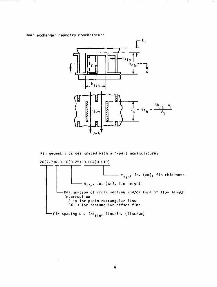
Heat exchanger geometry nomenclature
"7 A
Fin geometry i s designated with a 4-part nomenclature:
20(7.9)R-0. l0(0.25)-0.004(0.0l0)
tfin' in. (cm), fin thickness
in. (cm), fin height
Designation of cross section and/or type of flow length interrupt ion
R i s for plain rectangular fins R O i s for rectangular offset fins
Fin spacing N = I/bfin, f ins/in. (f ins/cm)
4
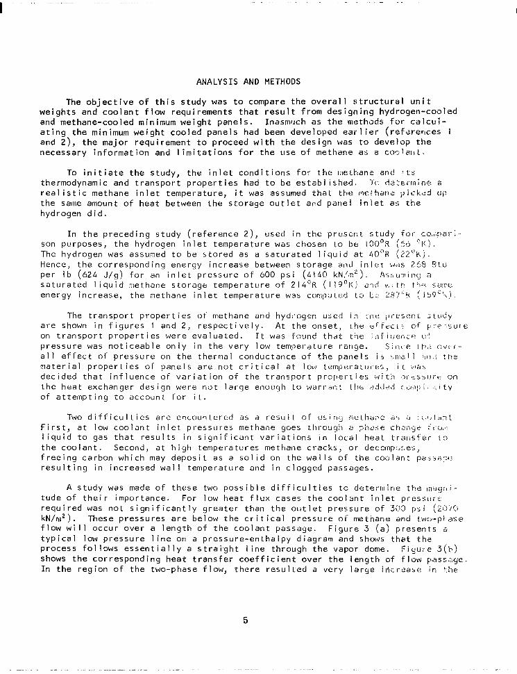
ANALYSIS AND METHODS
The o b j e c t i v e o f t h i s s t u d y was t o compare t h e o v e r a l l s t r u c t u r a l u n i t we igh ts and coo lan t f l ow requ i remen ts t ha t resu l t f r om des ign ing hyd rogen-coo led and methane-cooled minimum weight panels. Inasmuch as t h e lrlethods f o r c a l c u i - a t i n g t h e minimum weigh t coo led pane ls had been deve loped ear l ie r ( re fe rences I and 2), t he ma jo r requ i remen t t o p roceed w i th t he des ign was t o d e v e l o p t h e necessary in fo rmat ion and l i m i t a t i o n s f o r t h e u s e o f methane a5 a COOISIII.
To i n i t i a t e t h e s t u d y , t h e i n l e t c o n d i t i o n s f o r t h e r x l h a n e ant! '1:s thermodynamic and t r a n s p o r t p r o p e r t i e s had t o be es tab l i shed . Tc rlsl'er~min": a r e a l i s t i c methane in le t t empera tu re , i t was assumed t h a t t h e r w t h a n l p i c k e d lJt?
t he same amount o f h e a t be tween the s to rage ou t l e t a rd pane l i n le t a:; t h e hydrogen d id .
I n t h e p r e c e d i n g s t u d y ( r e f e r e n c e 2) , used i n t h e p r e s e c t s t u d y f o r C G , < ~ ~ ! E ~ I - ~ -
son purposes, the hydrogen in le t temperature was chosen LO b t 130'R ( 5 6 ' X ) . The hydrogen was assumed t o be s tored as a sa tu ra ted 1 i q u i d a t 4 0 " R (22 'k j . Hence, the corresponding energy increase between storage anJ i n l e t ~ ~ 3 s 265 B t u per l b (624 J /g ) f o r an i n l e t p r e s s u r e o f 600 psi (4140 kN,'m'). A s S u n 1 i ; l q a s a t u r a t e d 1 i q u i d methane storage temperature of 2 1 4 ' R ( I 19"1<,) 3;:d v . : t h th; , sa iw energy increase, the methane in let temperature was cor: lp:J led t o 1;;; ?i(7'1( ( 1 5 9 ' h ) .
The t r a n s p o r t p r o p e r t i e s o f methane and hydrogen u s e d i n :ne ; ~ r r s e r ! ~ r ; t : ~ d y are shown i n f i g u r e s I and 2, r e s p e c t i v e l y . A t the onset, [.he e r t c : c t . nf F J : ' ~ : , s u I ~
on t ranspor t p roper t i es were eva lua ted . It was found that the ; , l f I~;el;ce t:: pressure was n o t i c e a b l e o n l y i n t h e v e r y low temperature ronge. S i n t e !I>.:; C J C T -
a l l e f f e c t o f p r e s s u r e on the thermal conductance of the panels i s :,IxI 1 :,11,; t he m a t e r i a l p r o p e r t i e s o f p a n e l s a r e n o t c r i t i c a l a t lw temperatur-eS, i t was dec ided t ha t i n f l uence O F v a r i a t i o n o f t h e t r a n s p o r t p r o p e r t i e s ~ ~ i t h i:);r-h!,~.trt: on the heat exchanger design were not large enough to warral-it r>d*.l-d :"t ,y: i .- , : . i ty o f a t t e m p t i n g t o a c c o u n t f o r i t .
Two d i f f i c u l t i e s a r s encountered a s a r e s u l t o f u L i r l g !mt:Lhar-.e FJ', 11 : ; r , l *n t F i r s t , a t low c o o l a n t i n l e t p r e s s u r e s methane goes ttlrodqh a p h d i e chdl igc ' f ! ' < J . , !
l i q u i d t o gas t h a t r e s u l t s i n s i g n i f i c a n t v a r i a t i o n s i n loca l heat t r a l l s t ' e r 1 3
t h e c o o l a n t . Second, a t h igh tempera tures methane crack5: or decolnpr,c,es, f ree ing carbon wh ich may depos i t as a sol i d on t h e w a l l s o f t h e c o o l a ~ t passis::.: r e s u l t i n g i n i n c r e a s e d w a l l t e m p e r a t u r e and in c logged passages.
A study was made o f t h e s e two p o s s i b l e d i f f i c u l t i e s t c d < ~ t e r n l i n e the ~ n d g ~ ~ i -
tude o f the i r impor tance. For low heat f lux cases the coo lan t in le t pres:;urc r e q u i r e d was n o t s i g n i f i c a n t l y g r e a t e r t h a n t h e o u t l e t p r e s s u r e o f 303 p~ i (2ir j ' /G kN/n12). These p r e s s u r e s a r e b e l o w t h e c r i t i c a l p r e s s u r e of methane and t.1A:j-pi ase f l o w will occur over a l eng th o f the coolant passage. F igure 3 (a ) p resents 6
t y p i c a l low p r e s s u r e l i n e on a pressure-enthalpy d iagram and shows t h a t t h e p r o c e s s f o l l g w s e s s e n t i a l l y a s t r a i - g h t l i n e t h r o u g h t h e v a p o r dome. F i g u t e 3 ( b ) shows t h e c o r r e s p o n d i n g h e a t t r a n s f e r c o e f f i c i e n t o v e r t h e l e n g t h o f f low passt;y6:. I n t he reg ion o f t he two-phase f l ow , t he re resu l ted a ve ry l a rge irict-eahc: i n t . 1 w
5

h e a t t r a n s f e r c o e f f i c i e n t . F o r an a c t u a l a p p l i c a t i o n t h e i n c r e a s e i n t h e h e a t t r a n s f e r c o e f f i c i e n t w o u l d r e s u l t i n a m ino r i nc rease i n t he coo lan t f l ow requi rement . However, f o r t h e p u r p o s e s o f t h e p r e s e n t s t u d y a un i fo rm ne t heat f l u x t o t h e p a n e l was assumed and t h e i n f l u e n c e o f phase change on coolant requi rements was no t cons idered.
The in f luence o f the phase change on the s t ruc tu ra l des ign was found t o be n e g l i g i b l e . The ne t e f fec t o f the phase change, as shown b y f i g u r e SC, i s t o g rea t l y reduce t he l oca l t empera tu re l eve l f o r t he hea ted su r face and t o a l t e r s l i g h t l y t h e b a s i c a l l y l i n e a r t e m p e r a t u r e d i s t r i b u t i o n a l o n g t h e l e n g t h o f t h e c o l d w a l l ( i . e . s t r u c t u r a l p a n e l ) . The r e s u l t i n g r e d u c t i o n i n t h e t e m p e r a t u r e d i f f e r e n t i a l between the heated surface and t h e c o l d w a l l ( a l s o shown i n f igure 3c) wou ld tend to reduce the thermal s t resses in the heated sur face t h e r e b y i n c r e a s i n g t h e f a t i g u e l i f e . However, due t o the degradat ion o f m a t e r i a l p r o p e r t i e s w i t h i n c r e a s i n g t e m p e r a t u r e t h e c r i t i c a l d e s i g n r e g i o n o c c u r s a t t h e h o t end o f t h e p a n e l and phase change has no net effect on the des ign of the heated sur face . S imi la r ly , the thermal s t resses wh ich a re p roduced in the s t r u c t u r a l p a n e l b y t h e n o n - l i n e a r i t y o f t h e t e m p e r a t u r e d i s t r i b u t i o n OCCUI' i n a n o n - c r i t i c a l a r e a and do no t in f luence the pane l des ign .
To a v o i d s e r i o u s d i f f i c u l t i e s a s s o c i a t e d w i t h methane cracking, the methane ou t l e t t empera tu res must be below tha t wh ich w i l l resu l t in heat exchanger fou - l i ng by carbon depos i t ion . A l i t e r a t u r e s e a r c h was made t o a s c e r t a i n a v a i l a b l e d a t a on c rack ing and d e p o s i t i o n r a t e s o f methane f lowing in passages . F igu re 4 presents methane crack ing react ion ra tes f rom two sources. The compu ta t i ona l p rocedure ou t l i ned i n re fe rence 8 was used to es t ima te ca rbon depos i t t h i ckness f o r t he p resen t s tudy w i th t he assumpt ions t ha t t he methane was a t o u t l e t t e m p e r a t u r e f o r t h e l a s t 2 0 percent of the passage length and t h a t a l l of the carbon produced by c r a c k i n g was depos i ted . These assumptions are a11 b e l i e v e d t o b e c o n s e r v a t i v e . The pe r iod f o r ca rbon accumu la t i on was chosen t o be 100 h r . The c a l c u l a t i o n s w e r e made f o r t h e maximum h e a t f l u x l e v e l o f 500 Btu / f t2 -sec (5680 kW/m2) and f o r a 2 - f t (61-cm) heat exchanger passage designed w i t h an o f f s e t ' f i n h a v i n g 20 f i n s p e r i n c h w i d t h ( 7 . 9 f i n s p e r cm) and 0.003 i n . (0.0076 cm) t h i c k n e s s i n a passage 0.05 in. ( 0 . 13 cm) h igh . The r e s u l t s o f t h e c a l c u l a t i o n s f o r o u t l e t t e m p e r a t u r e o f 1800'R (IOOO'K) and 2000'K ( I I IO'K) are p resented in Tab le I , a long w i th in fo rmat ion concern ing carbon film charac- t e r i s t i c s and methane flow.
The r e s u l t s i n d i c a t e t h a t f o r a p e r i o d o f up t o 100 h r t h e e f f e c t s o f c a r - bon d e p o s i t i o n on hea t exchanger pe r fo rmance a re i ns ign i f i can t f o r ou t l e t ternp- e ra tu res up t o 1800'R ( IOOO'K). A t 2000'R ( I I IO'K) t h e e f f e c t s become n o t i c e a b l e . As a consequence, the des ign ca l cu la t i ons f o r t he me thane-coo led s t r u c t u r e w e r e made f o r c o o l a n t o u t l e t t e m p e r a t u r e s o f 1400°, 1600' and 1760'R (778', 889', 978'K).
Cooled Panel Concepts Studied
The two cooled panel concepts used in the present comparison of methane and hydrogen as coolants were developed in a genera l s tudy o f minimum weight regen- e ra t i ve l y coo led pane ls , re fe rence I . In tha t s tudy these concepts were shown to p rov ide nea r op t imum s t ruc tu ra l pane ls f o r spec i f i c ranges o f comb ina t ions
6

o f h e a t i n g and load ing and are, t he re fo re , cons ide red t o be rep resen ta t i ve o f p r a c t i c a l minimum we igh t regenera t i ve l y coo led pane ls . The procedures fo r ach iev ing a minimum we igh t des ign f o r a s p e c i f i e d c o m b i n a t i o n o f h e a t i n g and l o a d i n g i s o u t l i n e d f o r e a c h o f t h e c o n c e p t s i n r e f e r e n c e s I and 2, as w e l l as the process of, and t h e j u s t i f i c a t i o n f o r , m a t e r i a l s e l e c t i o n . T h e r e f o r e , t h e d e s c r i p t i o n s o f t h e c o n c e p t s t h a t f o l l o w a r e b r i e f .
Concept I : a s i n q l e - l a y e r e d s a n d w i c ~ h p a n e l ( f i g u r e 51. - This concept u t i l i z e s t h e c a p a b i l i t y o f t h e s a n d w i c h p a n e l t o p r o v i d e s t r u c t u r a l l o a d - c a r r y i n q
- . - - . - . . "-
c a p a b i l i t y , as w e l l a s ' f l o w passages f o r ' t h e c o o l a n t . Hence, the pane l i s de- s igned to se rve as a hea t exchanger by ca r ry ing coo lan t i n te rna l l y wh i l e sup- p o r t i n g a un i fo rm ex te rna l l y app l i ed p ressu re l oad . The heat exchanger has a s t r a i g h t - t h r o u g h , s i n g l e - p a s s f l o w p a t t e r n and employs p l a i n f i n s . The concept was s e l e c t e d f o r i n c l u s i o n i n t h i s s t u d y , because i t was shown in re fe rence I t o e x h i b i t s i m p l i c i t y and l i g h t w e i g h t f o r l ow l oad - low hea t f l ux app l i ca t i on .
. -
Inasmuch as the panel will be h e l d f l a t b y t h e b a c k - u p beams, temperature di f ferences between the upper and lower panel face sheets will r e s u l t i n thermal s t resses tha t will load the panel in the same way as the app l ied normal load. Hence, the sheets and f i n s must be s i z e d t o w i t h s t a n d i n t e r n a l c o o l a n t pressure stresses, normal pressure shear and bending stresses, as w e l l as thermal s t resses.
Concept - . 2 : . ~ h e a t e x c h a n n ~ e ~ : m ~ t a l l u r q i c a l l y bonded- to2L.i-ms-panel ( f i g u r e 6).- A t h ighe r l oad ing cond i t i ons , i t was shown i-n re fTrence I t o be advantageous t o s e p a r a t e t h e s t r u c t u r e s r e l a t e d t o l o a d - c a r r y i n g and the rma l -p ro tec t i on func t i ons . Th i s separa t i on o f f unc t i ons p reven ts t he t he rma l s t ress and load s t ress f rom be ing add i t i ve . To meet t h i s r e q u i r e m e n t w i t h minimum weigh t , the heat exchanger was m e t a l l u r g i c a l l y bonded t o t h e s t r u c t u r a l m u l t i w e b p a n e l supported by beams. The heat exchanger has a s imp le , s t ra igh t - th rough, s ing le - pass f l ow pa t te rn and employs a r e c t a n g u l a r o f f s e t f i n g e o m e t r y .
Panel accessor ies. - A sketch showing the major accessor ies used in a de ta i l ed pane l des ign i s presented as f i g u r e 7 . The seal ing arrangement shown i n f i g u r e 7 ( b ) s a t i s f i e s t h e r e q u i r e m e n t f o r a l l o w i n g t h e p a n e l t o expand t h e r m a l l y w h i l e c o n t a i n i n g e x t e r n a l p r e s s u r e a p p l i e d t o one s i d e o f t h e p a n e l . The manifold arrangement shown i n f i g u r e 7 ( a ) i s the geometry using in making we igh t es t imates . The a t tachmen t c l i ps as i l l u s t r a t e d i n f i g u r e 7 ( c ) a r e b r a z e d t o t h e i n n e r s i d e o f t h e p a n e l s and b o l t e d t o t h e I-beams.
M a t e r i a l s . - The c h o i c e o f m a t e r i a l s i s in f luenced by the heat exchanger perfo-rmance i n t h a t s t r u c t u r a l w o r k i n g t e m p e r a t u r e i s the p r imary fac to r gov- e r n i n g t h e s e l e c t i o n of m a t e r i a l s . I n t h e c a s e of concept I, where the corn- p o s i t e s t r u c t u r e o p e r a t e s a t a re la t i ve l y h igh t empera tu re , t he sandw ich wou ld be fabr icated f rom Waspaloy. Inconel 7 1 8 was chosen fo r the back-up beams, a t tachment c l ips , and p ip ing . Has te l loy X was used fo r the man i fo lds . For concept 2, H a s t e l l o y X was chosen as the heat exchanger and m a n i f o l d m a t e r i a l . Incone l 718 was chosen as the pr ime load-carry ing panel , back-up I beams, a t tachment c l ips , and p i p i n g m a t e r i a l . As d i s c u s s e d m o r e f u l l y i n r e f e r e n c e I, t he ma te r ia l cho ices were based on c o n d i t i o n s e x i s t i n g f o r a c o o l a n t o u t l e t o f
7

1600'R (889'K) and a r e n o t n e c e s s a r i l y f u l l y o p t i m i z e d a t o t h e r c o o l a n t o u t l e t temperatures.
D e s i g n r e s t r a i n t s . - The same d e s i g n l i m i t a t i o n s w e r e imposed on b o t h t h e methane- and hydrogen-cooled panel designs. The l i m i t a t i o n s i n c l u d e d minimum gage r e s t r a i n t s , as w e l l as minimum coolant passage he ights , minimum o u t l e t pressure, maximum i n l e t p r e s s u r e , maximum design temperature, and r e q u i r e d l i The r e s t r a i n t s a r e t a b u l a t e d i n T a b l e 2 .
Pane l we igh t de termina t ion . - Tables 3 and 4 show t y p i c a l w e i g h t s as de r i v e d i n r e f e r e n c e I fo r pane l concepts I and 2, r e s p e c t i v e l y . The des ign cond i t i ons , ma te r ia l s , and m a t e r i a l t h i c k n e s s e s a r e i n d i c a t e d . The coo lan t b o t h cases i s hydrogen.
I
f e .
n
The geometr ic d i rnensionsas provided by the minimum weight design procedures were used t o d e t e r m i n e t h e component we igh t pe r un i t a rea . The component weights were then summed t o g e t t h e t o t a l u n i t p a n e l w e i g h t u s e d i n t h e c o m p a r i - sons t h a t f o l l o w .
RESULTS AND DISCUSSION
Coolant Mass Flow Requirements
For the purposes o f t he p resen t s tudy un i fo rm ne t hea t f l uxes were assumed ove r t he su r face o f t he pane l . Under such condit ions and w i t h s p e c i f i e d i n l e t and ou t l e t t empera tu res t he mass f l o w of c o o l a n t r e q u i r e d is dependent only upon t h e h e a t c a p a c i t y o f t h e c o o l a n t .
P r e s e n t e d i n f i g u r e 8 as f u n c t i o n s o f t h e n e t h e a t f l u x a r e t h e c o o l a n t requi rements for methane and hydrogen for the three coolant out le t temperatures considered. The f low ra tes a re based upon the ' t ranspor t p roper t ies and 1 i m i t a - t i o n p r e s e n t e d i n t h e s e c t i o n on a n a l y s i s and methods. The weight of methane r e q u i r e d t o accommodate a g i v e n h e a t f l u x f o r a f i x e d o u t l e t t e m p e r a t u r e i s from 4 . 5 t o 4.8 t imes tha t o f hydrogen. However, as a r e s u l t o f d i f f e r e n c e s i n l i q u i d d e n s i t y ( l i q u i d methane densi ty = 26 l b / f t 3 ( 4 1 6 kg/m3) ; l i qu id hydrogen d e n s i t y = 4.3 l b / f t 3 (69 kg/m3)), the methane volume required to accommodate a g iven heat load i s 20 t o 25 percent less than the hydrogen volume. I t shou ld be noted, however, t h a t i f the coo lan t ou t l e t t empera tu re f o r t he hyd rogen cooled panel was a l l o w e d t o r i s e t o t h e limit s e t b y t h e s t r u c t u r a l m a t e r i a l (a cond i t i on wh ich canno t be r e a l i z e d f o r t h e methane panel due t o assumed cok- i n g l i m i t a t i o n s ) o r i f t h e e f f e c t s o f phase change were considered (see ana!ysis and methods sec t ion) the vo lumet r ic requ i rements o f the methane coo led pane ls become less f avo rab le .
Heat Exchanger Performance
The pressure d rop and the rma l conduc tance f o r t he rec tangu la r p la in and o f f s e t f i n s u s e d i n t h e p r e s e n t s t u d y w e r e c a l c u l a t e d b y u s e o f t h e f r i c t i o n fac to r , f, and Colburn modulus, j, taken f rom re ference I I and shown as f u n c t - ions o f Reynolds number i n f i g u r e 9 . The c a l c u l a t i o n p r o c e d u r e i s d e s c r i b e d i n re fe rence 2 . R e s u l t s o f t y p i c a l c a l c u l a t i o n s f o r one p l a i n f i n h e a t e x c h a n g e r
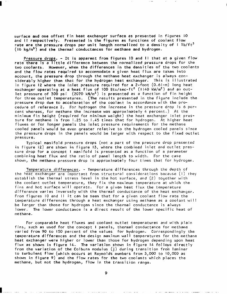
su r face and one o f f se t f i n hea t exchanger su r face as p resen ted i n f i gu res I O and I I respec t i ve l y . P resen ted in t h e f i g u r e s as f u n c t i o n s of c o o l a n t f l o w r a t e a r e t h e p r e s s u r e d r o p s p e r u n i t l e n g t h n o r m a l i r e d t o a dens i t y o f I 1 b / f t 3 (16 kg/m3) and the thermal conductances for methane and hydrogen.
Pressure drops. - It i s apparent from f i g u r e s IO and I I t h a t a t a g i v e n f l o w r a t e t h e r e i s a l i t t l e d i f f e r e n c e between the normal ized p ressure d rops fo r the two coo lan ts . However, when t h e d i f f e r e n c e s i n t h e d e n s i t i e s o f t h e two coolants and t h e f l o w r a t e s r e q u i r e d t o accommodate a g i v e n h e a t f l u x a r e t a k e n i n t o account, the pressure drop through the methane heat exchanger i s always con- s i d e r a b l y h i g h e r t h a n t h a t f o r t h e h y d r o g e n h e a t e x c h a n g e r . T h i s i s i l l u s t r a t e d i n f i g u r e 12 w h e r e t h e i n l e t p r e s s u r e r e q u i r e d f o r a 2 - f o o t (0.61-m) long heat exchanger operat ing a t a h e a t f l u x o f IO0 B t u / s e c - f t 2 ( I 140 kW/m2) and an o u t - l e t p r e s s u r e o f 300 ps i (2070 kN/m2) i s presented as a f u n c t i o n o f f i n h e i g h t f o r t h r e e o u t l e t t e m p e r a t u r e s . (The r e s u l t s p r e s e n t e d i n t h e f i g u r e i n c l u d e t h e pressure d rop due t o a c c e l e r a t i o n o f t h e c o o l a n t i n a c c o r d a n c e w i t h t h e p r o - cedure o f re fe rence 2 . For hydrogen the increase in the pressure drop i s 6 per - cen t whereas, f o r methane the increase was approx imate ly 4 percen t . ) A t t h e minimum f i n h e i g h t ( r e q u i r e d f o r minimum weigh t ) the heat exchanger in le t p res- s u r e f o r methane i s f r o m 1.25 t o 1 .45 t imes tha t fo r hydrogen. A t h igher heat f luxes o r fo r longer pane ls the in le t p ressure requ i rements fo r the methane cooled panels would be even g r e a t e r r e l a t i v e t o t h e h y d r o g e n c o o l e d p a n e l s s i n c e t h e p r e s s u r e d r o p s i n t h e p a n e l s w o u l d b e l a r g e r w i t h r e s p e c t t o t h e f i x e d o u t l e t pressure.
Typ ica l man i fo ld p ressure d rops (no t a pa r t o f t he p ressu re d rop p resen ted i n f i g u r e 12) a r e shown i n f i g u r e 13, where t h e combined i n l e t and o u t l e t p r e s - su re d rop f o r a concept I m a n i f o l d i s presented as a f u n c t i o n o f a parameter comb in ing hea t f l ux and t h e r a t i o o f p a n e l l e n g t h t o w i d t h . For the case shown, the methane pressure drop i s approx imate ly four t imes t h a t f o r h y d r
Temperature d i f ferences. - Temperature d i f ferences through the depth the heat exchanqer are imDortant f rom structural considerat ions because ( e s t a b l i s h t h e t h e r m a l s t r e s s l e v e l i n t h e h o t s u r f a c e , and ( 2 ) together w t h e c o o l a n t o u t l e t t e m p e r a t u r e , t h e y f i x t h e maximum tempera ture a t wh ich
og en.
o f ) they t h the
f i n s and ho t su r face w i 1 1 opera te . -Fo r a g i v e n h e a t f l u x t h e t e m p e r a t u r e d i f f e rence va r ies i nve rse l y w i th t he t he rma l conduc tance o f t he hea t exchanger . From f i g u r e s IO and I I i t can be seen t h a t f o r a g i v e n c o o l a n t f l o w r a t e t h e tempera tu re d i f f e rences t h rough a heat exchanger using methane as a coo lan t will be larger than those for hydrogen s ince the thermal conductance i s always lower. The lower conductance i s a d i r e c t r e s u l t o f t h e l o w e r s p e c i f i c h e a t o f methane .
For comparable heat f luxes and coo lan t ou t l e t t empera tu res and w i t h p l a i n f ins , such as used f o r t h e c o n c e p t I panels, thermal conductance for methane v a r i e d f r o m 90 t o 150 percent of the va lues fo r hydrogen. Cor respond ing ly the tempera tu re d i f f e rences and the des ign maximum wal l temperatures for the methane heat exchanger were h igher or lower than those for hydrogen depending upon heat f l u x as shcwn i n f i g u r e 1 4 . The v a r i a t i o n shown i n f i g u r e 14 folloys d i r e c t l y f r o m t h e v a r i a t i o n o f t h e C o l b u r n modulus ( j ) d u r i n g t r a n s i t i o n f r o m l a m i n a r t o t u r b u l e n t f l o w ( w h i c h o c c u r s a t R e y n o l d s numbers from 3,000 t o 10,000 as shown i n f i g u r e 9) and t h e f l o w r a t e s f o r t h e two coo lan ts wh ich p laces the methane, b u t n o t t h e h y d r o g e n , f l o w i n t h e t r a n s i t i o n r a n g e .
9
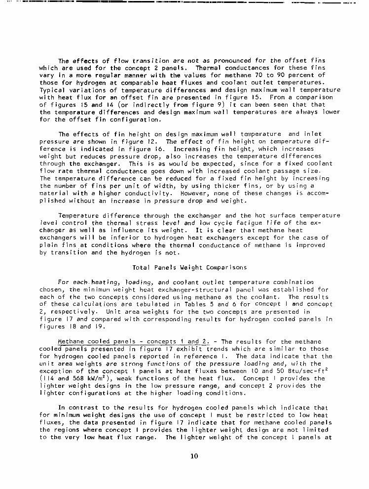
The e f f e c t s o f flow t r a n s i t i o n a r e not as pronounced f o r t h e o f f s e t f i n s wh ich a re used fo r the concept 2 panels. Thermal conductances f o r t h e s e f i n s v a r y i n a more regular manner w i t h t h e v a l u e s f o r methane 70 t o 90 p e r c e n t o f those for hydrogen a t comparable heat f luxes and coolant out le t temperatures. Typ ica l va r ia t i ons o f t empera tu re d i f f e rences and des ign maximum wa l l t empera tu re w i t h h e a t f l u x f o r an o f f s e t f i n a r e p r e s e n t e d i n f i g u r e 15. From a comparison o f f i g u r e s 15 and 14 ( o r i n d i r e c t l y f r o m f i g u r e 9) i t can been seen t h a t t h a t t h e t e m p e r a t u r e d i f f e r e n c e s and design maximum wal l temperatures are a lways lower f o r t h e o f f s e t f i n c o n f i g u r a t i o n .
The e f f e c t s o f f i n h e i g h t o n d e s i g n maximum wa l l t empera tu re and i n l e t p ressu re a re shown i n f i g u r e 12. The e f f e c t o f f i n h e i g h t on t e m p e r a t u r e d i f - ference i s i n d i c a t e d i n f i g u r e 16. Inc reas ing f i n he igh t , wh ich i nc reases weight but reduces pressure drop, a lso increases the temperature d i f ferences through the exchanger. This i s as would be expected, s ince for a f i x e d c o o l a n t f low ra te thermal conductance goes down w i th i nc reased coo lan t passage s i ze . The tempera ture d i f fe rence can be reduced fo r a f i x e d f i n h e i g h t by i nc reas ing t h e number o f f i n s p e r u n i t o f w i d t h , b y u s i n g t h i c k e r f i n s , o r b y u s i n g a m a t e r i a l w i t h a h i g h e r c o n d u c t i v i t y . However, none o f t hese changes i s accom- p l i s h e d w i t h o u t an i n c r e a s e i n p r e s s u r e d r o p and we igh t .
Temperature d i f ference through the exchanger and the ho t sur face tempera ture l eve l con t ro l t he t he rma l s t ress l eve l and low c y c l e f a t i g u e l i f e o f the ex- changer as wel l as i n f l u e n c e i t s we igh t . It i s c l e a r t h a t methane heat exchangers will be i n f e r i o r t o h y d r o g e n h e a t e x c h a n g e r s e x c e p t f o r t h e c a s e o f p l a i n f i n s a t c o n d i t i o n s w h e r e t h e t h e r m a l c o n d u c t a n c e o f methane i s improved by t r a n s i t i o n and the hydrogen i s n o t .
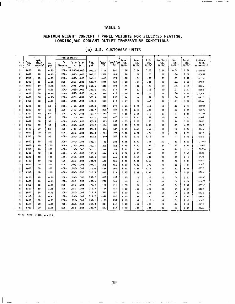
Total Panels Weight Comparisons
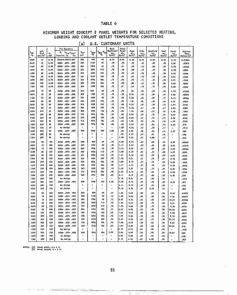
For each.heat ing , load ing , and coo lan t ou t le t tempera ture combina t ion chosen, t h e minimum weigh t heat exchanger -s t ruc tu ra l pane l was e s t a b l i s h e d f o r each o f t h e two concepts considered using methane as the coo lan t . The r e s u l t s o f t hese ca l cu la t i ons a re t abu la ted i n Tab les 5 and 6 for concept I and concept 2, r e s p e c t i v e l y . U n i t a r e a w e i g h t s f o r t h e two concepts are presented in f i g u r e 17 and compared w i t h c o r r e s p o n d i n g r e s u l t s f o r h y d r o g e n c o o l e d p a n e l s i n f i g u r e s 18 and 19.
Methane cooled panels - concepts I and 2. - The r e s u l t s f o r t h e methane coo led pane ls p resented in f igure- 17 e x h i b i t - t r e n d s w h i c h a r e s i m i l a r t o t h o s e fo r hyd rogen coo led pane ls repo r ted i n re fe rence I . The d a t a i n d i c a t e t h a t t h e u n i t a r e a w e i g h t s a r e s t r o n g f u n c t i o n s o f t h e p r e s s u r e l o a d i n g and, w i t h t h e excep t ion o f t he concep t I pane ls a t heat f luxes be tween IO and 50 B t u / s e c - f t 2 (114 and 568 kW/m2), weak f u n c t i o n s o f t h e h e a t f l u x . Concept I p rov ides t he l i g h t e r w e i g h t d e s i g n s i n t h e low pressure range, and concept 2 p rov ides t he l i g h t e r c o n f i g u r a t i o n s a t t h e h i g h e r l o a d i n g c o n d i t i o n s .
I n c o n t r a s t t o t h e r e s u l t s f o r h y d r o g e n c o o l e d p a n e l s w h i c h i n d i c a t e t h a t f o r minimum weight des igns the use o f concept I must be r e s t r i c t e d t o low heat f l u x e s , t h e d a t a p r e s e n t e d i n f i g u r e 17 i n d i c a t e t h a t f o r methane coo led pane ls the regions where concept I p r o v i d e s t h e l i g h t e r w e i g h t d e s i g n a r e n o t l i m i t e d t o t h e v e r y l o w h e a t f l u x r a n g e . The l i g h t e r w e i g h t o f t h e c o n c e p t I p a n e l s a t
10
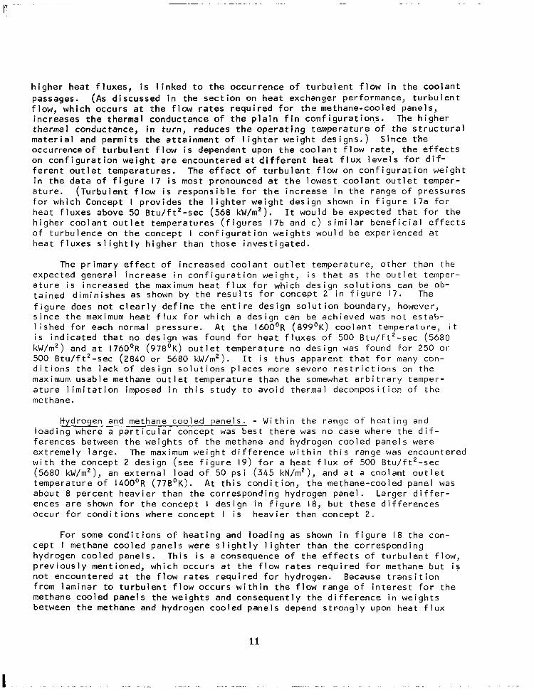
h i g h e r h e a t f l u x e s , i s l i n k e d t o t h e o c c u r r e n c e of t u r b u l e n t f l o w i n t h e c o o l a n t passages. (As d i s c u s s e d i n t h e s e c t i o n on heat exchanger performance, turbulent f l o w , w h i c h o c c u r s a t t h e flow ra tes requ i red fo r the methane-coo led pane ls , i n c r e a s e s t h e t h e r m a l c o n d u c t a n c e o f t h e p l a i n f i n c o n f i g u r a t i o n s . The h ighe r thermal conductance, in t u r n , r e d u c e s t h e o p e r a t i n g t e m p e r a t u r e o f t h e s t r u c t u r a l m a t e r i a l a n d p e r m i t s t h e a t t a i n m e n t o f l i g h t e r w e i g h t d e s i g n s . ) S i n c e t h e occurrence o f t u r b u l e n t f l o w i s d e p e n d e n t upon t h e c o o l a n t f l o w r a t e , t h e e f f e c t s on c o n f i g u r a t i o n w e i g h t a r e e n c o u n t e r e d a t d i f f e r e n t h e a t f l u x l e v e l s f o r d i f - f e r e n t o u t l e t t e m p e r a t u r e s . The e f f e c t o f t u r b u l e n t f l o w on c o n f i g u r a t i o n w e i g h t i n t h e d a t a o f f i g u r e 17 i s most pronounced a t t h e l o w e s t c o o l a n t o u t l e t t e m p e r - a tu re . (Tu rbu len t f l ow i s r e s p o n s i b l e f o r t h e i n c r e a s e i n t h e r a n g e o f p r e s s u r e s for which Concept I p r o v i d e s t h e l i g h t e r w e i g h t d e s i g n shown i n f i g u r e 17a f o r heat f luxes above 50 B tu / f t 2 -sec (568 kW/m2). It would be expec ted tha t fo r the h i g h e r c o o l a n t o u t l e t t e m p e r a t u r e s ( f i g u r e s 17b and c ) s i m i l a r b e n e f i c i a l e f f e c t s o f t u rbu lence on the concept I conf igura t ion we igh ts wou ld be exper ienced a t h e a t f l u x e s s l i g h t l y h i g h e r t h a n t h o s e i n v e s t i g a t e d .
The p r imary e f fec t o f i nc reased coo lan t ou t ' l e t t empera tu re , o the r t han t he expec ted genera l inc rease in con f igura t ion we igh t , i s t h a t as the ou t l e t t emper - a t u r e i s inc reased the maximum hea t f l ux f o r wh ich des ign so lu t i ons can be ob- ta ined d imin ishes as shown b y t h e r e s u l t s for concept 2 i n f i g u r e 17. The f i g u r e does n o t c l e a r l y d e f i n e t h e e n t i r e d e s i g n s o l u t i o n boundary, however, s i n c e t h e maximum h e a t f l u x f o r w h i c h a design can be achieved was no t es tab- l i shed fo r each normal p ressure . A t t h e 1600'R (899'K) coolant temperature, i t i s i n d i c a t e d t h a t no design was found fo r hea t f l uxes o f 500 B tu / f t 2 -sec (5680 kW/m2) and a t 1760'R (978'K) ou t l e t t empera tu re no des ign was found fo r 250 or 500 Btu / f t2 -sec (2840 or 5680 kW/m2). I t i s t hus apparen t t ha t f o r many con- d i t i o n s t h e l a c k o f d e s i g n s o l u t i o n s p l a c e s more seve re res t r i c t i ons on t h e maximum usab le methane ou t le t tempera ture than the somewhat a r b i t r a r y ternper- a t u r e l i m i t a t i o n imposed in t h i s s tudy t o avo id t he rma l decompos i t i on o f t he methane.
Hydrogen. and methane cooled panels. - Wi th in t he range o f hea t ing and loading where a p a r t i c u l a r c o n c e p t was bes t t he re was no case where the d i f - ferences between the weights of the methane and hydrogen cooled panels were ex t remely la rge . The maximum w e i g h t d i f f e r e n c e w i t h i n t h i s r a n g e was encountered w i th t he concep t 2 des ign ( see f i gu re 19) f o r a h e a t f l u x o f 500 B t u / f t 2 - s e c (5680 kW/m2), an e x t e r n a l l o a d o f 50 ps i (345 kN/m2), and a t a c o o l a n t o u t l e t t empera tu re o f 1400'R (778'K). A t th is cond i t ion , the methane-coo led pane l was about 8 percent heav ie r than the cor respond ing hydrogen pane l . Larger d i f fe r - ences are shown fo r t he concep t I d e s i g n i n f i g u r e 18, bu t t hese d i f f e rences occur fo r cond i t ions where concept I i s heavier than concept 2.
__i_ . _"
For some c o n d i t i o n s o f h e a t i n g and load ing as shown i n f i g u r e 18 t he cept I methane coo led pane ls were s l i gh t l y l i gh te r t han t he co r respond ing hydrogen cooled panels . Th is is a consequence o f t h e e f f e c t s o f t u r b u l e n p rev ious l y men t ioned , wh ich occu rs a t t he f l ow ra tes requ i red f o r methane no t encoun te red a t t he f l ow ra tes requ i red f o r hvd roqen . Because t r a n s i t
con-
t f low, b u t i s
I on f r o m l a m i n a r t o t u r b u l e n t f l o w o c c u r s . w ' i t h i n t h e ' f l o i r a n g e o f i n t e r e s t f o r t h e methane cooled panels the weights and c o n s e q u e n t l y t h e d i f f e r e n c e i n w e i g h t s between the methane and hydrogen cooled panels depend strongly upon h e a t f l u x
11

and coo lan t ou t l e t t empera tu re .
For concept 2 t he hyd rogen coo led pane ls were f ound to be cons i s ten t l y 1 igh ter than the methane coo led pane ls (see f igure 19) and t h e d i f f e r e n c e s i n w e i g h t w e r e r e l a t i v e l y i n s e n s i t i v e t o t h e v a r i a t i o n s i n h e a t f l u x and c o o l a n t ou t l e t t empera tu re . The lower we igh t fo l lows f rom the lower p ressure losses and the higher thermal conductances (hence lower f i n and f a c e p l a t e t e m p e r a t u r e s ) ob ta ined w i th hydrogen as a coo lan t . The l a c k o f s e n s i t i v i t y o f t h e d i f f e r e n c e s i n w e i g h t i s a t t r i b u t e d t o t h e r e l a t i v e i n s e n s i t i v i t y o f t h e t h e r m a l c o n d u c t a n c e and p r e s s u r e l o s s o f t h e o f f s e t f i n t o changes from laminar t o t u r b u l e n t f l o w , and t o t h e f a c t t h a t w e i g h t d i f f e r e n c e s w e r e i n t h e h e a t e x c h a n g e r and man i fo lds wh ich rep resen t on l y a s m a l l p o r t i o n o f t h e t o t a l w e i g h t f o r t h e c o n c e p t 2 de- s igns bu t a l a r g e p o r t i o n o f t h e t o t a l w e i g h t f o r t h e c o n c e p t l des igns.
CONCLUSIONS
An a n a l y t i c a l s t u d y has been made o f t h e d i f f e r e n c e s i n t h e r e g e n e r a t i v e l y coo led pane l we igh t and coo lan t f low requ i rements tha t a re assoc ia ted w i th the use o f methane and hydrogen as coo lan ts . The s t ruc tu ra l we igh t compar isons a re based on a minimum panel and heat exchanger weight analysis procedure developed in re fe rences I and 2. The s tudy was c a r r i e d o u t o v e r a range o f hea t f l uxes f rom I O t o 500 B tu / f t 2 -sec ( I 14 t o 5680 kW/m2) and a range o f a p p l i e d p r e s s u r e load ing f rom 6.9 t o 250 p s i (48 t o 1720 kN/m2) w i t h c o o l a n t o u t l e t t e m p e r a t u r e s o f 1400°, 1600°, and 1760'R (778, 889' and 978'K.) The more important con- c l u s i o n s a r e as f o l l o w s :
( I ) As a r e s u l t o f t h e d i f f e r e n c e s i n t h e thermodynamic and transport p r o p e r t i e s o f t h e two coo lan ts , t he we igh t o f me thane requ i red t o accommodate a g i v e n h e a t f l u x i s from 4.5 t o 4.8 t i m e s t h a t o f hydrogen. Because o f d i f f e r e n c e s i n d e n s i t y , t h e v o l u m e o f l i q u i d methane tankage required to accommodate a g iven heat load i s 75 t o 80 p e r c e n t o f t h a t f o r h y d r o g e n .
( 2 ) The greater f low requi rements more than o f fset the h igher dens i t y o f methane r e l a t i v e t o t h a t o f h y d r o g e n and r e s u l t i n g r e a t e r h e a t e x - changer and manifold pressure drops. The grea ter des ign con ta inment p r e s s u r e r e q u i r e d t o a f f o r d a g i v e n o u t l e t p r e s s u r e g e n e r a l l y r e s u l t s i n a heavier heat exchanger than that required for hydrogen. As a consequence, except f o r a ve ry l im i ted range o f condi t ions, methane- cooled panels were found to be heavier than hydrogen-cooled panels . Di f ferences in weights o f the methane-and hydrogen-cooled panels for t h e minimum weigh t des igns d id no t exceed 8 pe rcen t .
(3) The lower thermal conductance o f methane r e l a t i v e t o hydrogen resu l ts i n g rea te r t empera tu re d i f f e rences t h rough the hea t exchanger and a h igher work ing tempera ture fo r the ho t face o f the heat exchanger . As a consequence, methane-cooled heat exchanger design solut ions could n o t b e o b t a i n e d a t t h e h i g h e r ' o u t l e t t e m p e r a t u r e s and h e a t f l u x l e v e l s .
12

(4) Limited analysis indicated that , within the range of the present invest igat ion, the e f fects of l iquid- to-gas phase change and thermal decomposition of the coolant on the structural design o f the methane-cooled panels were negligibly small .
13

REFERENCES
I .
2.
3.
4.
5.
6 .
7.
8.
9.
IO.
I I .
Flieder, W. G . ; Richard, C. E.; Buchmann, 0. A.; and Walters, F. M.: An Analytical Study of Hydrogen Cooled Panels For Application t o Hypersonic Aircraft. NASA CR-1650, 1970.
Walters, F. M.; and Buchmann, 0 . A.: Heat Transfer and Fluid Flow Analysis of Hydrogen Cooled Panels and Manifold Systems. NASA CR-66925, .July 1970.
Weber, Richard J. ; Dugan, James F. ; and Luidens, Rober W. : Methane- Fueled Propulsion Systems. Astronautics and Aeronautics, Vol. 4 , No. I O , October 1966.
Whitlow, J. B., Jr; Eisenberg, J. D.; and Shovlin, M. D . : Potential of Liquid - Methane Fuel for Mach 3 Commercial Supersonic Transports. NASA TN D-347 I, 1966.
McAdams, W . H.: Heat Transmission. Third ed., McGraw-Hill Book Co., Inc., 1954.
Maxwell, J. B.: Data Book on Hydrocarbons. Eighth ed., D. Van Nostrand Co., Inc., 1965.
Anon.: Properties o f Para Hydrogen.. Rep. 9050-6S, Aerojet General Corp., PRA-SA-DSR-30, September 1963.
Nelson, W . L. : Reaction Rates in Cracking. The Oil and Gas Journal, Col. 38, No. 24, October 26, 1939, p. 132.
Murphy. D. .B.; Palmer, H. B.; and Kinney, C. R.: A Kinetic Study o f the Deposition o f Pyrolytic Carbon Films. Society o f Chemical Industries, London, England, Conference Proceedings, September 24-26, 1957.
Johnson, V . J . : A Compendium of the Properties o f Materials at Low Temperature (Phase I), Part I, Properties of Fluids. WADD Technical Rept., 60-56, July 1960.
Kays, W. M. ; and London, A. L: Compact Heat Exchangers. Second ed., McGraw-Hill Book Co., Inc. (New York), 1964.
14

TABLE I
DEPOSITION OF CARBON FOR A 100-HR PERIOD
Panel Condi t ions
Length = 2 f t (61 cm)
Leng th o f un i fo rm ca rbon depos i t = 0 . 4 f t ( 1 2 cm)
O f f s e t f i n g e o m e t r y = 20(7 .9)R0-0 .050(0 . 127) -0 .003(0 .0076)
Dura t ion = 100 h r
Heat f l u x = 500 Btu /sec - f t { 5680 kW/m2)
". Carbon F i l m P r o p e r t i e s
Thermal c o n d u c t i v i t y = 2.42 Btu/hr-ft-OR ( 3 . 8 8 W/m-OK)
Dens i ty = 0 .0749 l b / i n . 3 ( 2 0 7 0 kg/m3)
Methane Cond i t ions
I n l e t t e m p e r a t u r e = 287'R (159 'K )
Out le t p ressure = 300 p s i ( 2 0 7 0 kN/m2)
Out let temperature, O R (OK) 1800 ( 1000) 2000 ( I I IO)
F l o w ra te , 1 b/sec-f t (kg/s-m) 0 . 7 2 4 ( I . 0 8 ) 0 .632 (0 .942 : ,
Out l e t d e n s i t y , 1 b / f t ( kg/m3) 0 . 2 4 9 ( 3 . 9 8 ) 0 . 2 2 4 ( 3 . 5 8 )
Mol f rac t ion c racked/sec 3 . 5 x 1 0 - 5 4 . 7 x 1 0 - 4
Resu l ts of Ana lys i s
Carbon depos i t ion ra te , lb /sec- f t (kg /s -m) 9 X IO-' 109 x 10-9 ( 1 3 . 4 x 1 0 - 9 ) ( 1 6 . 2 x 10⁻⁹:
Deposited carbon film th ickness , in . (cm) 0 .0002 l (0 .000534) 0 .00254(0 .00646) ( a c c u m u l a t i o n f o r 100 h r )
Tempera tu re d i f f e ren t i a l t h rough ca rbon 1 3 ( 7 . 2 ) f i l m , O R (OK)
157( 8 7 )
AP w i t h carbon/AP clean 1.014 I . 19
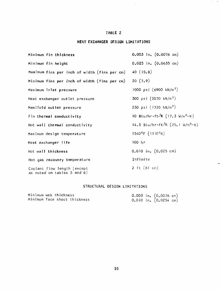
TABLE 2
HEAT EXCHANGER D E S I G N L I M I T A T I O N S
Minimum f i n t h i c k n e s s
Minimum f i n h e i g h t
Maximum f i n s p e r i n c h o f w i d t h ( f i n s p e r cm)
Minimum f i n s p e r i n c h of w i d t h ( f i n s p e r cm)
Maximum i n l e t p r e s s w r e
Heat exchanger ou t le t p ressure
M a n i f o l d o u t l e t p r e s s u r e
F i n t h e r m a l c o n d u c t i v i t y
Hot w a l l t h e r m a l c o n d u c t i v i t y
Maximum des ign tempera ture
Heat exchanger 1 i f e
Hot wa l l t h iGkness
Hot gas recovery temperature
Coo lan t f l ow l eng th (excep t as no ted on tab les 5 and 6 )
0.003 in. (0.0076 cm)
0.025 in. (0.0635 cm)
40 (15.8)
20 (7.9)
1'300 ps i (6900 kN/m2)
300 ps i (2070 kN/rn2)
250 p s i ( 1720 kN/rn2)
I O Btu/hr-ft-OR (17.3 W/mo-K)
14.5 Btu/hr-ft-OR (25. I W/rno-K)
I 54OoF ( I I IO OK)
100 h r
0.010 in. (0.025 crn)
I n f i n i t e
2 f t (61 cm)
Minimum web t h i c k n e s s Minimum face sheet th ickness
STRUCTURAL DESIGN LIMITATIONS
0.003 in. (0.0076 crn) 0.010 in. (0.0254 cm)
16
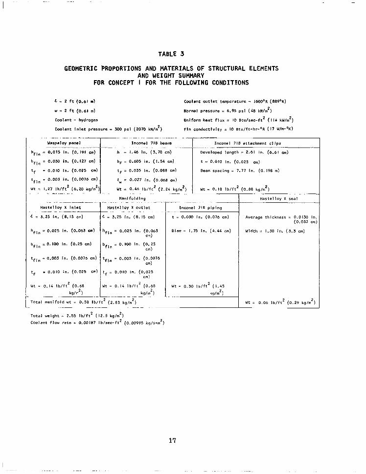
TABLE 3
GEOMETRIC PROPORTIONS AND MATERIALS OF STRUCTURAL ELEMENTS AND WEIGHT SUMMARY
FOR CONCEPT I FOR THE FOLLOWING CONDITIONS
4 = 2 f t (0.61 m) Coolan t ou t le t tenpera ture = IM)OoR (889'K)
w = 2 f t (0.61 rn) Normal pressure = 6.95 p s i (48 kN/m2)
Coolant = hydrogen Un i fo rm hea t f l ux = I O 8 tu /sec - f t2 (110 k w h 2 )
Coo lan t I n le t p ressu re = 300 psi (2070 kN/m2) F l n c o n d u c t i v i t y IO Btu / f t -h r - 'R ( I7 W/m'K)
. .. -. . "_ Warpaloy panel
hfln = 0.075 In. (0. 191 cm)
bfin = 0.050 In. (0.127 cm)
tf = 0.010 In. ( 0 . 0 2 5 cm)
tf i n = 0.003 In. (0.0676 cm)
W t = 1.27 I b / f t 2 (6.20 kg/rnZ: .~ ~ ~
- ~. . ~
Has te l i oy X I n l e t
4 = 3.25 in. (6.15 cm) " ~
hfin = 0,025 in. (0.063 cm)
bfln = 0 . 100 in. (0.25 cm)
tfin = 0.003 in. (0.0076 cm)
tf 3 0.010 in. (0.025 cm)
Wt = 0.16 i b / f t ( 0 . 6 8 2
kg/lr2) "
___. - .. .. ~
Inconel 718 beams
h = 1.46 in. (3.70 cm)
bF = 0.605 in. (1.54 cm) t = 0.010 In. (0.025 cm)
tF = 0.035 In. (0 .088 cm) Beam spacing = 7.77 in. (0. 198 m)
tw = 0.027 in. (0.068 an)
.
-T Inconel 718 at tachment c l ips ". . . ... . ~ " -~ ~
length = 2.61 in. (6.61 cm)
U t = 0.46 i b / f t 2 (2.24 I b / f t 2 ( 0 . 8 8 kg/rn2)
~- . . ~ -. . . . . . ~ ~ - f l a n l f o l d i n g
Has te l l oy X o u t l e t
c = 3.25 in. ( 8 . 15 cm)
~~
__ .. ~. . .
hfIn = 0.025 in. (0.063 cm 1
bfIn = 0. 100 in. (0. 25 cm)
tfin = 0.003 in. (0.0076 c d
t - 0.010 In. (0.025 f - cm 1
U t = 0.14 I b / f t (0.68 2
kg/m2) ~ ~
. .
Inconel 718 p i p i n g
t = 0.030 In. (0.076 cm)
Dlam = 1.75 In. (6.44 cm)
W t = 0 . 3 0 I b / f t 2 ( 1 . 4 5
kg/rn2
T o t a l m a n i f o l d w t = 0.58 I b / f t 2 (2.83 kg/rn
Tota l weight = 2.55 l b / f t 2 ( 1 2 . 5 kg/m2)
Coolant f lw r a t e = 0.00187 I b / sec - f r2 (0.00915 kg/.wn2)
2
. _ . _ _ _ ~ "" ~ .
Has te l i oy X seal
Average thickness = 0.0130 in. (0.033 cm)
Width = 1.30 In. (3.3 crn)
Ut = 0.06 I b / f t 2 ( 0 . 2 9 kg/rn ) 2
17

TABLE 4
GEOMETRIC PROPORTIONS AND MATERIALS OF STRUCTURAL ELEMENTS AND WEIGHT SUMMARY
FOR CONCEPT 2 FOR THE FOLLOWING CONDITIONS
4 = 2 ft (0.61 m)
w = 2 f t (0.61 m)
Coolan t ou t le t tempera ture = I600'R (889'K)
Normal pressure = 100 ps i (689 kN/m2)
Coolant = hydrogen Unl form heat f lux = 250 B tu /sec - f t2 (2860 kW/m2)
Coo lan t I n le t p ressu re = 630 ps l (4340 kN/m ) 2 F i n c o n d u c t i v i t y = IO Btu/ft-hr-OR (17 W/m-'K)
Has te l l oy X heat exchanger I Inconel 718 prlme panel ___
hfin = 0.027 in. (0.069 cm)
U t = I . I I Ib / f t 2 (5 .42 kg/m2) W t = 0.72 I b / f t z (3.51 kg/m2)
tC = 0,0052 in. (0.0132 cm) tfin = 0.003 in. (0.0076 an)
t f = 0.010 in. (0.0254 cm) tf = 0.010 in. (0.025 rm)
bf = 0.258 in. (0.656 cm) bfln = 0.050 in. (0. 127 an)
h = 0.293 In. (0.745 cm)
Has te l l oy X i n l e t
Man i fo ld ing
Has te l l oy X o u t l e t
hfIn = 0.0% in. (0.127 cm)
bfin = 0.100 In. (0.2% cm) ,
hfin = 0.162 in. (0.361 cm)
bfln = 0. 100 in. (0.251 cm: t f = 0.0135 in. (0.0313 cm)
L = 3.25 in. (8.25 cm)
d t = 0 . 2 6 i b / f t 2 ( 1 . 2 7 2
kg/m )
Inconel 718 beams
h = 3.34 in. (8.48 an)
b F = 1.22 in. (3.09 cm)
t F = 0.072 in . (0. I83 cm)
tW = 0.053 in. (0. 135 cm)
U t = 3. 19 I b / f t 2 (15.6 kg/rn2)
~-
T Diameter =
(4.4 crn) 1.75 in .
Thickness = 0.030 in . (0.076 an)
= 0.30 I b / f r 2 ( I. 46 kg/m2)
Seals
Width = 1.30 in. (3 .3 cm)
Average th ickness =
0.049 in. (0. 124 cm)
At tachment c l ips
Developed width = 3.26 in. ' (8 .18 cm)
Thickness = 0.010 in, (0.025 cm)
Beam spacing = 4.70 in.
(0.120 m )
Wt = 0.37 I b / f t 2
( I. 80 kg/m2) ~ __ "
Tota l we igh t = 6.37 I b / f t 2 (31. I kg/m2)
Coolant flow r a t e = 0.0468 ib/f t2-sec(0.22S kg/s-m ) 2
L, f t
2
2
2
2
2
2
2
2
2
2
2
2
2
2
2
2
2
2
2
2
2
2
2
2
2
2
2
5
5
5
5
5
5
5
5
5 -
7- ~~
TCO, O R
1400
I600
I 7 6 0
1400
I600 I 7 6 0
1400
I600
I 7 6 0
1400
1600
I760
1400
1600
I760
1400
1600
I760
1400
I600
I 7 6 0
1400
1600
I 7 6 0
1400
"
1600
1760
1400
I600
I 7 6 0
1400
I600
I 7 6 0
1400
I600
I 764
_____
q/A, Btu/ *C -rt'
I O
10
10
so 50
50
l o o
IO0
1 0 0
10
10
10
50
30
so 1 0 0
1 0 0
I O 0
10
10
10
50
50
50
1 0 0
I00
IO0
10
10
10
50
50
50
IO0
1 0 0
IO0 __ MOTE: Panel width,
TABLE 5
MINIMUM WEIGHT CONCEPT I PANEL WEIGHTS FOR SELECTED HEATING, LOADING,AND COOLANT OUTLET TEMPERATURE CONDITIONS
( a) U. S. CUSTOMARY UNITS
T ' Fln b a a t r y
P'L P I
6.9s
6.95
6.95
6.95
6.9s
6.95
6.9s
6.95
6.95
50
50
50
50
30
50
so 50
so
1 0 0
1 0 0
1 0 0
1 0 0
1 0 0
1 0 0
1 0 0
1 0 0
I00
6.95
6.95
6.95
6.93
6.95
6.95
6.95
6.95
6.95 __
.L I
. 2 f t
", h f l d t f I " n flns/In:l!. ,. In.
2OR- 0.050-0.003
2 L " .050- .003
20R- .050- .003
ZOR- .050- .003
20R- .025- .W3 2011- .025- .003
2" .oso- .003
ZOR- .025- .003 3OR- .025- .003
20R- .150- .003 3OR- . l50- .003 3OR- . 150- .003 20R- . loo- .003 AOR- .050- .003 &OR- .050- .003 3011- .IO& .003
4OR- .050- .003 4OR- .050- .003
3OR- . 150- .003
30R- .150- .003 4OR- .150- .003 4OR- .150- .003 4OR- .150- .003 40R- .050- .003
4OR- . 1 0 0 - .003 4011- .050- .003
40*- .05& .003
20R- .050- .003 20R- .050- .003 20R- .050- .003
ZOR- .050- .003 20R- .050- .003 ZOR- .050- .003
2oR- .050- .003
20R- .050- .003 20R- .050- .003
. ~ - ~
-~ .~
T PCI,
-~ P' I
300.2
300.2
xx). 2
302.9
316.6
313.6
310.8
355.9
362.5
300.0
300. I wo. I 300.5
303.7
303.0
303. I
316.6
313.3
300. I 300. I
500. I 300.4
300. 5
303.0
304. I
316.6
313.3
300.7
300.5
300.5
315.3
313.3
311.7
353. I
344.3
338.9
Tonu' OF
I141
1328
1475
I270
I338
1517
1355
1392
1519
1215
I295
1443
I560
1423
I604
I464
1434
1619
I l l 0
I295
I399
I414
I586
1604
I396
1434
1619
1073
1284
I44 I
I I24
I327
1491
I173
1381
I547
~
~
-
'ow- Tc O F
20 I
I88
175
330
198
217
415
252
219
275
I 5 5
I63
620
283
w 4
524
294
319
I 7 0
I55
99
474
446
304
4%
294
319
I33
144 I41
184
187
191
233
241
247
~~
"_
-
'am I u t ,
b/f ta
I .20
I .20
I .20
I .20
1.14
I. I 4
1.20
1.14
1.17
I .46
I .65
I .65
I .33
I .33
I .33
I .46
I .33
I .33
I .65
1.65
1. 84
1.U 1 . 8 6
I .33
1.59
I .33
I .33
I .20
I .20
1.20
I .20
I .20
1 . 2 0
I .20 1.20
I .20
-
__
-
Beam * t 8
I b / f tz
0.50
.51
.56
.52
.56
.63
.53
.58
.64 2 . 2 0
2.12
2.31
2.50
2.69
3.09
2.47
2.73
3. I 3
3.79
3.77
3.96
4.03 4.48
5.51
4.28
4 . 8 8
5.58
.49
. 5 0
. 5 4
. 5 0
.M
.56
.51
.52
.58
~
"
-
C I I p Ut I
I b / f t '
0.23
.23
.30
.25
.32
.43
.25
.34
.43
. 4 2
.37
.48
.58
.73
I . 08
.52
.77
1 . 1 2
.56
.55
.66
.67
.89
I .59
.78
1.13
I .t4 .22
.22
.28
.22
.23
.30
.23
.24
.33
~
~
Fanifo ld u t ,
I b / f t z
0.59
.59
.59
.70
.70
.70
.71
.71
.71
.59
.59
.59
.70
.70
.70
. 7 1
. 7 1
. 7 1
.59
.59
.59
.70
.70
.70
.71
.71
.7 I
.42
.42
. 42
.61
.61
.61
.62
.62
.62
Sea I W t ,
Ib/f tz
0.06
.(M
.07
.06
.06
.07
.a5
.06
.07
. I 6
. I 6
. I 7
. I 6
. 16
. I 7
. I 6
. 16
. I 7
. 2 3
.23
. 2 4
.23
.23
.24
.23
.23
.24
.@6
.04
.04
.@6
.04
.04
.@6
.of.
.04 -
Tota l W t I
I b/ f tz
2.58
2.59
2.72
2.73
2 . 1 8
2.97
2.75
2.83
3.02
4.83
4.89
5.20
5.27
5.61
6.37
5.32
5.70
6.46
6.82
6.79
7.27
7.47
8.14
9.37
7.59
8.28
9.52
2.37
2.38
2.48
2.57
2.58
2.71
2.60
2.62
2.77
- nethane
ra te , Ib /scc - f t ' "
0.01045
.00872
.00766
.0509
.043b
.0383
. IO45
.0872
,0766
.01045
.00872
,00766
,0509
,0136
,0383
. IO45
.0b72
,0766
,01045
,00872
,00766
,0509
,0436
,0383
. IOL5
.0n72
.0766
.01045
.0087?
,00760
. 0 M'?
,0430
.0383
. I O 4 5
,0872
.0766
19
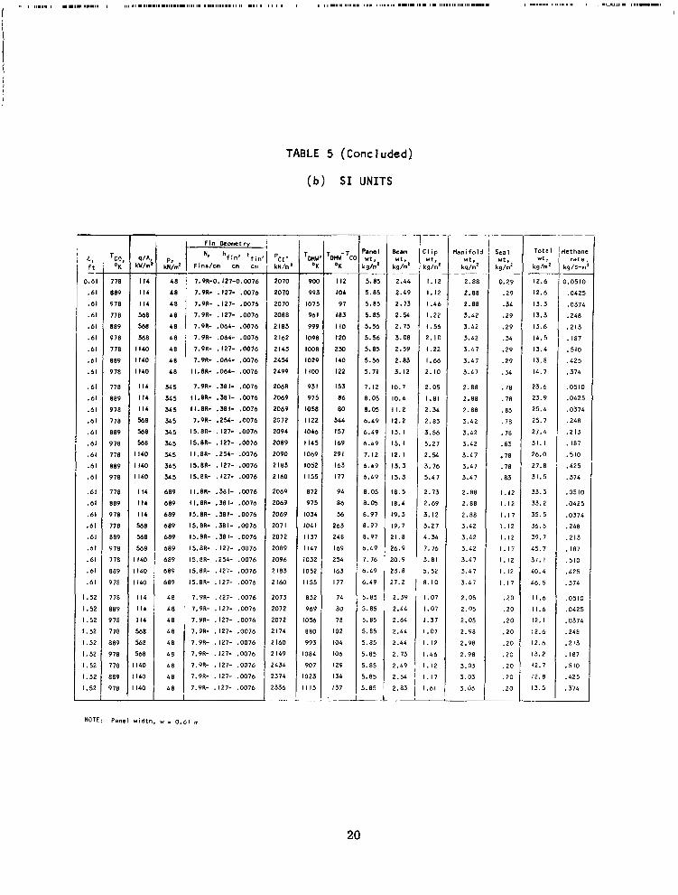
TABLE 5 (Concluded)
(b) S I U N I T S
c, f t
0.61
.61
.61
.61
.61
.61
.61
.61
.61
.61
.61
.61
.61
.61
.61
.61
.61
.61
.61
.61
.61
.61
.61
.61
.61
.61
.61
I .52
I .52
I .52
I .52
I .52
I. 52
I .52
I. 52
1.52
"
-
TCO OK' -
7 78
889
978
778
889
978
778
889
978
778
889
978
778
889
978
778
889
978
778
889
978
778
889
978
778
889
978
778
889
978
778
889
978
778
889
978
kY/m V A
I I 4
I I 4
I I4
568
568
568
I I40
I140
I140
I I 4
I I 4
I I 4
568
568
568
I I60
I140
I140
I I 4
I I 4
I I4
568
568
5 6 8
I 140
I140
I140
I14
I14
I I 4
568
568
568
I40
I 40
140
- 48
4 8
48
48
4 8
48
4 8
4 8
345
x 5
545
3 5
345 345
345 345 365
689
689
689
689
689
689
689
689
689
4 8
4 8
4 8
7.9R- . 127- .W76
7.9R- .127- .0076
7.9R- . 127- ,0076
7.9R- .064- .0076
7,S'R- .064- ,0076
7.9R- .127- .0076
7.9R- .064- ,0076
II.8R- ,064- .W76
7.9R- .%I- .W76
II.8R- .SEI- .W76
I I .8R- .381- ,0036
7.9R- .254- .0076
I5.8R- .127- .0076
15.8R- .127- .0076
I1.8R- .254- .W76
15.8R- . 127- ,0076
15.8R- .127- .W76
II.8R- .381- .0076
11.8R- ,381- .0076
15.8R- .381- .0076
15.8R- ,381- .W76
I5.8R- .SEI- .0076
I5.8R- ,127- .0076
15.8R- .254- .0076
15.8R- ,127- .0076
15.8R- . 127- .0076
7.9R- ,127- ,0076
7.9R- . 127- .0076
7.9R- ,127- .0076
4 8 7.9R- .127- .0076
4 8 7.9R- ,127- .0076
& 8 7.9R- ,127- .0076
4 8 7.9R- .127- ,0076
4 8 7.9R- .127- ,0076
4 8 7.9R- .127- ,0076
'
i
pcI *
- k N h '
2070
2070
2070
2088
2183
2 I62
2 I43
2454 2499
2068
2069
2069
2072
2094
2089
2090
2 I83
2 I60
2069
2069
2069
207 I
2072
2089
2096
2 I83
2 I 60
2073
2072
2072
2 174
2 I 60
2 119
2434
2374
2336
".
TOnU O K
9oc
992
107:
96 I
999
1098
l 0 0 E
1029
1 1 0 0
93 I 97 5
1058
I122
I046
I145
1069
1052
I155
872
975 1034 101 I
I I37
I 1 4 7
1032
IO52
I55
852
969
056 880
993
084
907
023
I I 5
- row- '
OK
I I2
104
97
I83
I10
I20
2x) I40
I22
I 53
86
80
344
157
I 69
29 I
163
177
94
86
56
263
2 4 8
I69
254
I 63
I77
74
80
78
102
104
106
129
I34
137
_=
1 ~ ""
'am W f . ,
.g/m'
5.0: 5.0:
5.81
5.0:
5.5!
5.5t 5.8: 5. %
5.71
7.12
8.05
8.05
6 .49
6.49
5.49
7. 12
5.49
5.49
E.05
3.05
3.97
3.97
3.97
i . L9
1 . 76
,.4
i.49
i. 85
I . 85
). 85
,. 85 ,. 85 I. 85
I. 65 1. 85
8. 85
_ _
. .
&m w t ,
kg/mz
2 .44
2.49
2.73
2.Y. 2.73
3.08
2.59
2.83
3.12
~"
10.7
10.4
11.2
12.2
13. I
15. I
12. I
13.3
15.3
18.5 18.4
19.3
19.7
! I . 8
!6.9
!O. 9
!3.8
! 7 , 2
2.39
2.44
2.64
2.44
2.44
2. 73
2.49
2.54
2.83
: l i p
q / m ' W f .
1 . 1 2
1 . 1 2
I .46
I .22
I .56
2 .10
I .22
I .66
2.10
2 . 0 5
1.81
2.34
2.83
3.56
5.27
2.54 3.76
5.47
2.73
2.69
3.12
3.27
4 . 3 4
7.76
3.81
5.52
8.10
I .07
1.07
I .37
I .07
1.12
I .46
1 . 1 2
1.17
1.61
~ ~~
bbnifolc W t .
kg/rn2
2.88
2.88
2.88
3.42
3.42
3.42
3.47
3.47
3.47
2 . 8 8
2.88
2.88
3 . 4 2
3 . 4 2
3.42
3.47
3 . 4 7
3.47
2 . 8 8
2.88
2.88
3.42
3.42
3.42
3.47
3 . 4 7
3.47
2.05
2.05
2.05
2.98
2.98
2.98
3.03
3.03
3.03
- "- ~
"
Sea I wt , kgh' ~-
0.29
.29
.34
.29
.29
.34
.29
.29
.34
.78
.78
.83
.78
. 78
.63
.78
.78
.83
1.12
1.12
1.17
1.12
1.12
1.17
1 . 1 2
1.12
1.17
.20
.20
.20
. 2 0
.20
.20
. 2 0
.20
.20
T Tota l Ut 3
kg/m2
12.6
12.6
13.3
13.3
13.6
14.5 13.4
13.8
14.7
23.6
23.9
25.4
25.7
27.4
31. I
26.0
27.8
31 .5
33.3
33.2
35.5
36.5
39.7
45.7
37. I
40.4
46.5
11.6
11.6
12. I
12.6
12.6
13.2
12.7
12.8
13.5
-
__
'ietham rate
kg/s-m
0.0510
.0h25
,0374
,248
.213
.187
.510
.425
.374
,0510
,0425
.0374
,248
.213
. 187
.510
.425
.374
.0510
.0h25
.0374
. 2 4 6
.2 13
.187
,510
,425
.374
,0510
,0425
.0374
.248
.2 13
.187
. 5 10
,425
.374
-
__
NOTE: Panel width, w I 0.61 m
20
- TCO’
OR
I400 I600
I760 1400
I600 I IC0
1400 I600 I760
I400
I400 I760 1400 1600
I160 I400 1600
1760 I400 It00 1160 1400 1.500
I760
1400 I M K ) I160 1400
- .
I too I760 1400 I600
I760 1400
I 6OO I160 1400 1600 I160
1400
I600 I160 1400 1600 I160 l4W 1600
I160 ILW
16oa I760 l4W 160C
I76C -
TABLE 6
MINIMUM WEIGHT CONCEPT 2 PANEL WEIGHTS FOR SELECTED HEATING, L O A D I N G A N D COOLANT OUTLET TEMPERATURE CONDITIONS
- sf&
ws-f t’ Btul - IO 10 IO 50
50
100 50
1 0 0 IO0
IO 10
IO 50 50
50 100
100
100
250 250
250 500
Mo 500
IO IO IO 50 50 50
1 0 0 IO0 I 0 0 250 250
250 500 500 500
IO IO IO 50 50 %
1 0 0 l o o IO0 250 250 2 50 500 500 500 -
- p. P S I - 6.95 6.95 6.95 6.95
6.95 6.95 6.95
6.95 6.95
50
5n 50 50
50 50
50 50
50 50
50
50 50 50 50
1 0 0 1 0 0 1 0 0 I 0 0 1 0 0 100
1 0 0 l o o I00
I 0 0 1 0 0
I00
100
IO0 100
250
250 250 250 250 250 250 250 2 5 0 250
250 250
250 250 250 -
F l n k m t r y
N, hfIn,.tfln* i lnr l ln . In. In.
20RO-0.025-0.003 2ORc- .02c .003 20RO- .02c .003 ZORO- A25- .003 2ORO- .02c .003 2ORO- . a 2 5 .oo3 ZORO- .02e .003 ZORC- .025- .003 3 0 R O - . o z c .003
20RO- .02e .003
2 0 ~ 0 - .ozs .003 2ORO- .025- .003 20RO- .O2b .oo3 20RW . 0 2 c .003 20RO- .02c .003 ?OR* . 0 2 c .003 ZORO- .025- .003
.ozc A03
Z O R O - .Ole- .W3
3 0 R O - .a%- .003 Ho deslgn
40RO- .072- .W3
No dorlgn
No deslgn
20RO- .02c .W3
ZORO- .025- -003 2ORO- .025- .003 Z O R O - .025- .003 20RO- .025- .003 20Rc- .025- .003 ZORO- .ozc -003 20RW .025- .003 MRO- . 0 2 c .003 ZORO- .038- .003 MRO- ,050- .003
40RW .072- .003 No deslgn
Ho deslgn
No deslgn
ZORO- .025- .003 20R* . O Z b .w3 Z O R O - .02b .003 ZORO- .025- .003 2ORw .025- .003 2ORO- .02C .003 20RW .025- .w3 2ORO- .026 .oo3 30m- .025- .oo3 2ORO- .038- .005 3 0 R O - . o s .003 No deslgn
4ORO- ,072- .W3
NO deslgn NO design
305 305 304 388
314 364 580 532 555
M 5 305 304 388 374 544
580 532 545 716
M 3
830
345 305
304 388 374 3M 580
532
545 716
563
830
M 5 305 304 388 374 364 580 532 545 116
563
830
- u.: TPnW
OF
989 I I89
1 3 8 1052
I253 I409 1096 1296 1433
989 I189
1348
1052 1253 1409 1096 I296 1433 1076
1276
-
1046
989 I189 1348 I052
1253 1409 1096 1296 I433 1076
1276
1046
989 I I89 1348
1052 1250
1409 1096 1296 I433 1076
1276
1046
>. cu ’ l W i T C
-
- OF
49 49
48
I12 I IO I09 1%
I 5 6 1 3 3
49 b9
68 I12 I IO
109 1 5 6
1 5 6
I 3 3 IM 1%
106
49 69
I I2 48
I10 109 1 5 6 1% I33
IM IM
106
49 49 48
I12
I IO 109 I56 1 5 6
133
1%
I36
106
I s1 rOMARY U H I T S - k a t
rchsngel ut ,
I b l f t ’
0.R .R .72
.n
.n
.R
.R
.R
.75
.72
.72
.R
.72
.R
.R
.R
.72
.75
.75
.85
-
I .03
.12
.72
.R
.n
.R
.72
.n
.72
.15
.75
.85
I .03
.12
.72
.72
. 12
. 72 -12
.72
.72
.75
.75
.85
1.05
21
- Prim P a M l
b l f t’
3.93 .93 .91 .93
.93 .91 .93
.93
.91
.95
.95
. 00
.95 -95
1 . 0 0
-95 .95 .oo .95 .95 .oo .95 -95 . 00
-08
. I I
.08
.I8
. I I
.I8
.08
. I I
. I8
.08
. I I
. I 8
.08
.I1
.I8
.86
.93
. I2
.e4
.93
. I2
.86
.93
. I2
.86
.93
. I2
.86
.9J
. I 2
-
-
k a a
0.11 0.38
lGi2 l b l f >
C I Ip
.39 . I 2
.49 .I5
.38 . I I
.39
. I 5 .49
. I2 .39
. I l .38
. I 5 .49
. I2
.94 .Y 2.07 .37
2.26 .41 1.94 2.4 2.07 .37
2.26 AI 1.94 .Y 2.07 .31
2.26 .41 I.P4 .Y 2.01 S 7 2.26
.LI 2.26 3 7 2.07 .34 1.94 .41
1-10 .37 3-19 .31 3.51 .4I 3-10 .37 3.19 .31
3.51 .41 S.10 .37 3.19 .37 3.51 , .41 S.10 3 1 S.19 .31
S.51 .4l 3.10 .37 5.19 .37
3.51 .4l
5.49 .38 5.66 .38 5.26 .42 5.49 .38 5 .66 .38 5.26 .42
5.49 .38 5 . 6 6 .38 5.26 .42 5.49 .38 5 . 6 6 .38 b.26 .42
5.49 .38 i.66 .38 5.26 .42
w t
- Wnlfold
* t r 1 b l f t‘
0.59 .59
.59
.70
.70
-10
.71 . 71
.71
.59
.59
.59
. 10
.70
. 10
.12
.73
.17
.85
.86
.90
.95
.96 1 . 0 0
.59 ,59 ,59 .70
.70
.70
.12
.73
.77
.85
.86
.90
.95
1.00 .96
.59
.59
.59 . 10
.70
.70
.72
.73
.77
-85
.86
.90 -95 .96
I .w
-
-
Seal wt.
I b l f t’
0.06 .05
.07
.06
.06
.07
.06
.06
.07
.I6
. I 6
.I7
.I6
.I6
. I 7
.I6
.I6
-11 .I6
. I6
. I 7
. I6
.I6
.I7
.23
.23
.24
2 3 .23
.24
-23
.23
.24
.23
.23
.24
-23
.23
.24
.M
.M
.38
.36
.38
.56
.%
.M
.38
.36
.36
.38
.36
.36
.38
-
-
- Total
ut, l b l f t‘
2.19 2.81
2.93 2.90
2.92 3.m 2.91 2.93 3.08
4.70
4 . a
5. I 5 4.81 4.97 5.26 4 . a 5.00 5.36 4.99 5.26
-
5.37
6.09
6.21
6.65 6.20
6.32
6.76
6.22
6.35 6.86
6.38 6.61
6.76
9.40 9.66 0.49 9.51 9.75 0.60
9.53 9.18 0.70
9.69 0.m
0.07
-
- kthane
Fate. blsec-ft
O.OIC45 .00812
.00166
-0509
.04M
.0383
.1045
.0b72
.0166
.01045
.00872
.00766
.059
.04M
.053
.1045
.0n12
.01&
.2545
.218
.1915
.539 -4% .383
.01045
.00812
.00166
.059
.04M
.0383
.1045
.0812
.2545
.07M
-218
.1915
.539
.436
.383
A1045 .W872
A0766 .0539 .0436 .0383 .1045 .0872 .0766
.2545
.218
.1915
.539
.4M
.383 ”
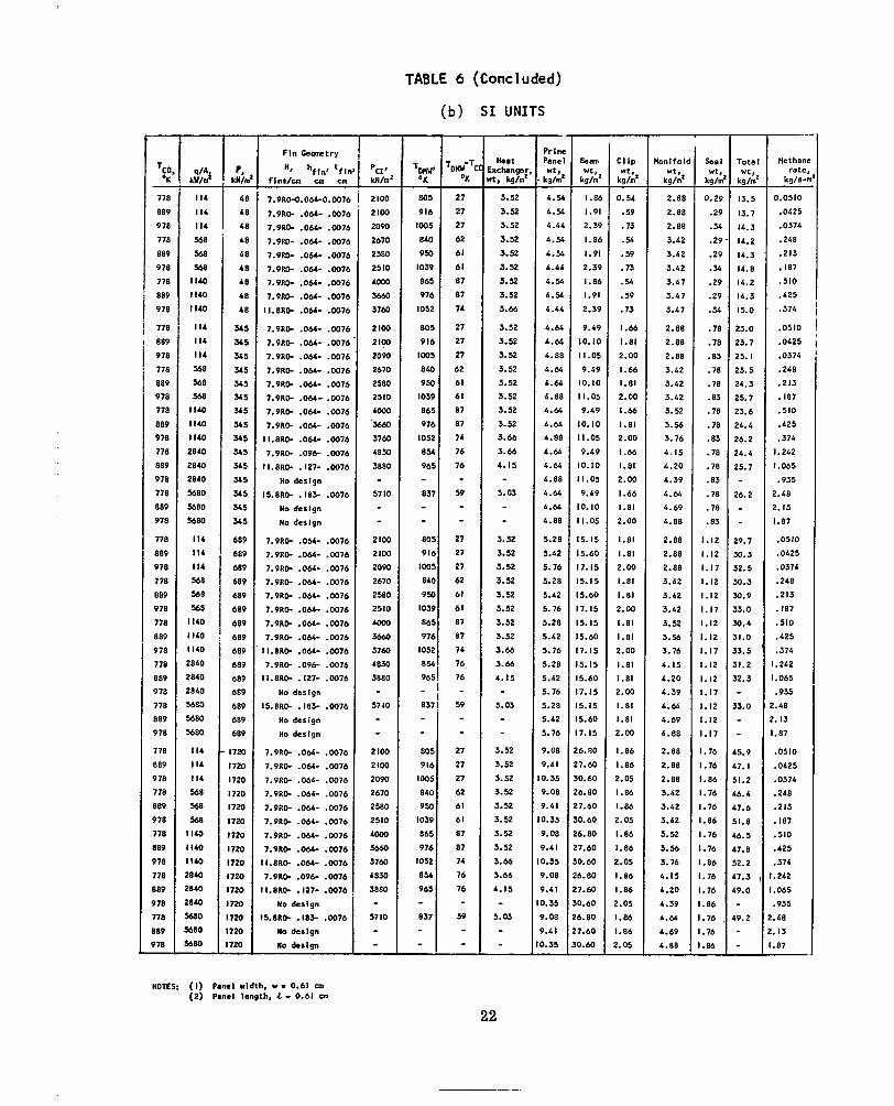
TABLE 6 (Conc 1 uded)
(b) SI UNITS - TCO - OK
778
889
978
778
889 978 778 889
978
778
889
978
778
889
978
778
889
978
778
889
978
778
889
978
778
88P 978
7 78
889 978 778 889
978
778 889
978 778 889
978
778
889
978
778
889
978
778
889
978
778
889
978
778 889
978 -
k d
I I4
I I4 I I4
568
568 568
I I 4 0 I140
I140
I I4
I14
I I 4
568 %8 MB
1 1 4 0
I140
I 1 4 0 2840
2840 2840 5680 5680
5680
I14 I14 I I4 568 568
568 I140 I 1 4 0 I140 2840
2840
2840
5680 5680
5680
I I4
I I4 I I4
568
568
568
1 1 4 0
I I40
I I 4 0 2840 2840
m40 5680
5580
s80
PIA -
-
T T
i I i
- I I I
I I
I
I I
I I I
I ' I'
I ' I:
L
p, - U / n
6t
O f
4 f
4 f
Of 4 I
4f
&e 48
34: 3 4 5 3 4 5
245
345
345 345
345
345
345
345 345
245
345 345
689
689
689
689 689
689 689
689
689
689
689
689
689
689
689
17.W
720 720
720 720
720
720 720
720 720 720
720 720 720 7 2 0 -
Fln b o n t r y
Hn hfln* ttll fins/- ca
?.PRO-O.0M-O.W?t
7.9R0- . O M - .w7t
7.9RD- .064- .W7t
7.9Fa- .OM- .007t
1.9" .OM- .W7(
7.9Ro- .OM-
7.9- .OM- .007e
7.9" ." .w7c II.8R0- .OM- .007e
7.9R0- .ou- .007c
7.9R0- .OM- .m7c
7.9R0- .OM- .w7c 7.9R0- . O M - .w7e 7.9R0- . O M - .0076
7.9R0- . O M - -0076
7.9" .OM- .W76
7.9" .OM- .W76
I I . B R 0 - . O M - .0076
7.9R0- . 0 9 6 .0076
II.8R0- .127- .0076 No design
I5.8R0- .183- .W76
No deslgn No deslgn
7.9R0- .OM- .W76
7.9R0- .OM- .0076
7.9R0- .OM- .0076
7.9R0- .OM- .W76
7.9R0- . O M - .0076
7.9R0- . O M - .0076
7.9R0- .OM- .W76
7.9R0- . O M - .0076
I I . 8 R 0 - . O M - .W76
7 . 9 ~ 0 - . o w .oox l l . 8R0- . 127- .0076
No design 15.8RW .IS?.- .W76
No design No design
7.9RW . O M - . W 7 6
7.9R0- .064- .0076
7.9RW -064- .W76
7.9R0- .064- .W76
7.9R0- .OM- .0076
7.9R0- .Obi- .0076
7.9R0- .OM- .0076
7.9R0- .OM- ,0076
l l .8R0- . O M - .0076
7.9110- .09+ .0076
11.8110- .127- .0076
No design I5.8R0- .I83- .W76
YO dSSlgn
no d.Slgn
pcI' - M/ma
2 100
2100
2090
2670
2580
2510
1ooo 36m 3760
2lW 2 I W 2090
2610 2580 2510
4000
j660 3760
4830
3880
57 10
2100
2100
2090
2670
2580
2510
bow 36m 3760
4830 3880
57 IO
2lW
2100
2090
2670
2580
2510
uwx)
36m 3760
4830
54880
57 IO
TOWY' - OK
805
916
loo5 810 950
1039
865
976
I052
805 916 I005 840 950
1039
865
976
I052 8%
965
837
805
916
I005 8bO
950
1039
865
976
1052
856 965
837
805
916
ID05 840
950
1039
865
976
1052
8% 965 ~
- I - f " ~
'DHb-Tl
- O K
27
27
27
62
61
61
87
87
74
27
27
27
6 2
61
61
87 87 74
76
76
59
27
27
27
62
61
61
87 87 74
76
76
59
27
27
27
62
61
61
87 87 74
76
76
54
xchngsr t, @/ma
Heat
- 3.52
3.52
3.52
3.52
3.52
3.52
3.52
3.52
3.66
3.52 3.52
3.52
3.52
3.52
3.52
3.52
3.52 3.66
3.66
4. I5
5.03
3.52
3.52
3.52
3.52 3.52
3.52
3.52
3.52
3.66
3.66 4. I5
5.03
3.52 3.52
3.52 3.52
3.52
3.52
3.52 3.52
3.66
3.66
4.15
5.03
- Pr I n x Panel
kg/.' *t,
4.56
4.56
6.44
6.56 4.56
6-44
4 . Y
4.56 4.44
4.64
4.64
4.88 4.66
6-66
4.88 4.64 4-66 4.88 4.64 4.66
4.88 4.66 4.64
4.88
5.28
5.42
5.76
5.28 5.42
5.76
5.28 5.42
5.76
5.28
5.42
5.76
5.28 5.42
5.76
9.08
9.41 3.35
?.08
?.AI 1.35
9.08
8.41
1.35
P.08 P.41
1.35
1.08 1.41
L 3 5
- "
I
I
I
I
I
I
I
I
I
I I I
I I I I I
I
I I I I I
28
2
31
21
2
31
PC
2'
31
21
2 :
31 21
2;
3t -
Beem w t , kg/m
I .81 1.9
2.3'
1.81 1.9
2.3!
I . & 1.91 2.3!
9.41
10.1(
I I .O!
9.45
10.1c
11.0:
9.49
1O.IC 11.05
9.49
0. IO I .os 9.49
0. IO I .05
5. I5 5.60
7. I5
5. I5 5.60
7.15
5. IS 5.60
7.15
5.15
5.60
7 . IS 5. IS 5.60
7. IS
6.90
7.60
0.60
b.80 7.60
3.60
5.80
7.60
1.60
5.80
-
1.60
1.60
5.80 1.60
L60 -
T Clip *t, kg/m'
0.54
-59
.73
.Y
.59
-73
.56
.59
. 73 I .66 1.81 2.00
I .66
I .81 2.00
I .66 I .81 2.00
I .66
1.81 2.00
I .66
1.81
2.00
1.81 1.81 2.00
1.81 1.81 2-00
1.81 I .81 2.00 1.81 1.81 2.00 1.81 1.81 2.00
1.86
1.86 2.05
1 . 8 6
1-86 2.05
I .86
1-86
2.05
1.86
I .86 !.OS
1.86 1.86
!. 05
- bnlfol
kg/m' *tt
2.88
2.88 2.88 3.42 3.42
3.42 3.47 3.47 3.47
2.88
2.88
2.88
3.42
3.42
3.42 3.52
3.56 3.76 4.15
4 .20
4.39
4 . M
4.69
4 .88
2.88 2.88
2.88
3.42
3.42
3.42
3.52 3.56 3.76 4.15
4.20
4.39
4.64 4.69
4 .88
2.88
2.88 2.88
3.42
3.42 3.42 3.52
3.56
3.76
4.15
4.20
4.39
4 . M
4.69
4.88
- see
kg/#
0.2s
.2'
.3
.2!
.2!
.Y
.21
.21
.Y
.7f
.7f
.83
.78
W t
-
.7a
.83
. 7 8
.78
.83
.78
.78
.83
.78
.78
.83
1.12
1.12 1.17
I. I2
. I 2
. I 7
. I 2
.I2 -17
. I 2
. I 2
. I 7
.I2
.I2
.I7
.76
.76
.86
.76
.76
.86
.76
.76
.86
.76
.76
.86
.76
. 76
.86
1 - Tots
W t , kg/m - 13.5
13.7 14.3
14.2
14.3
14.8
14.2
14.3
15.0
23.0 23.7 25. I
23.5
24.3
25.7
23.6 26.4
26.2
24.4
25.7
26.2
29.7 30. 3 32.5
30.3 30.9
33.0
30.6
31.0
33.5
31.2
52.3
33.0
65.9
17. I
51.2
16.4
$7.6
51.8
16.5
$7.8 52.2
L7.3
19.0
19.2
"-
Methane rate,
kg/s-m
0.0510 .0b25
.0374
. 2 4 8
.213 . I87
.510
. 425
.374
.0510
.0425
.0374
. 2 4 8
.213
. 187
.510
.425
.374 I. 242 1.065
.935
2.48
2. I3 1.87
.0510
.0425
.0374
.248
.213
. 187
.510
. 425
.374
. 242
.065
.935
'.48 . I 3
.87
.0510
.0425
.0374
.248
.213
. 187
.510
.425
.374
.242
.065
.935
* 48
. I 3
-87 -
NOTES: (I) Panel wldth, w - 0.61 0.
(2) Panel length. 4 - 0.61 u a
22

(555) (1110)
Temperature, O R ( O K )
Figure I. T r a n s p o r t P r o p e r t i e s of Methane Gas and Liquid

16
12
IO
8
6
f4
2
(278)
F igure 2. Transport Propert ies o f Para-Hydrogen Gas
3 ( 555 1
Temperature, O R (OK)
24

Forced 1 i q u i d
.- VI 9.
U \ m 3 UJU ~ r n
c o n v e c t i o n
" . ~
Forced c o n v e c t i o n ____)
Process 1 i n e F r-"" I
-167 -155 5 789 ( -390 ) (-361) ( 12) ( 1840)
Enthalpy, Btu/ lb (J /g)
i gu r e
Figure
3a
3b
0 4 . 3 ( 10.9)
Panel length, in. (an)
- 1500 (834) P,
3 1000 ( 5 5 5 )
a- 500 (278)
L
m-- aJ0
E
I--0 aJe
L Y Figure 3c a n d methane
0 4 . 3 ( 10.9)
Panel length, in. (cm)
F igure 3. Typical Effects of Methane Phase Change on Panel with Heat Flux of 100 Btu/sec- f t * ( I 140 kW/m2) 'and O f f s e t F i n Geometry, 20(7.9)R0-0.025(0.063)-0.003(0.0076)
25
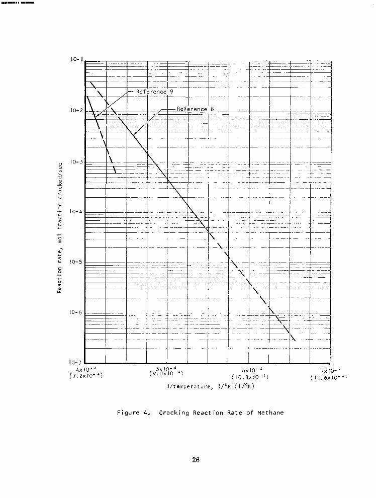
U a, rn \
c c. .- u u rg L
LL
0 E - W
m L
+I
c 0 .- +I U m W CT
IO- 1
10-2
10-3
10-4
10-5
10-6
10-7 4 x IO- '
(7.2x10- d , ( 9 . 0 ~ I O - ') 5x 10- sx 10-
( 1 0 . 8 ~ 1 0 - ~ ) 7x IO- '
(I2.6xlO-'' ]/temperature, I/'R ( 1 1 ' ~ )
F i g u r e 4 . Cracking React ion Rate o f Methane
26

F i g u r e 5. Single Layered Sandwich Panel (Concept I )
27
" .. . . . ." .
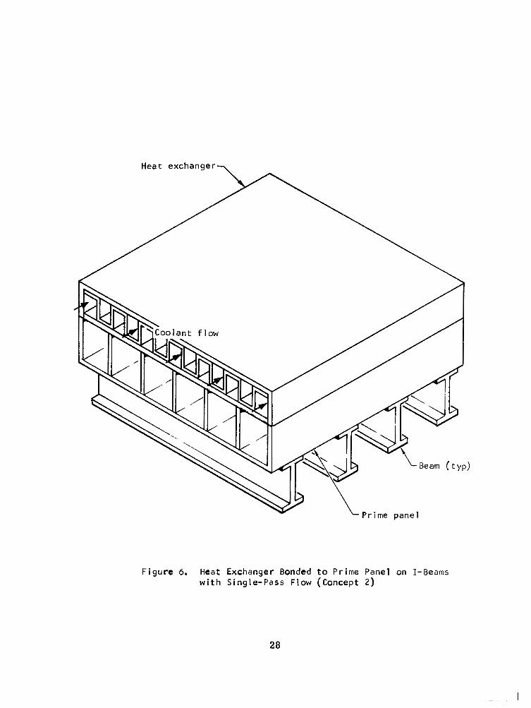
Heat exchanger-
Figure 6. Heat Exchanger Bonded to Prime Panel on I-Beams w i t h S i n g l e - P a s s Flow (Concept 2 )
28

r
Pr
Heat exchanger 7
Applied p r e s s u r e
h i 4 4 4
-_ )Lo I 2
panel layout
x Beam c. Panel-to-beam attachment
v LPanel lower sheet
Figure 7. Panel Accessories
29

.6(2.93)
5( 2.44)
e 4( I 9 5 )
3( I 4 7 )
. 2 ( . 9 7 8 )
. I ( . 4 7 9 )
0
I Legend
Methane "" Hydrogen
= 1400'R TCo (778'K) I \
Ti
I TCO = 1600'R (889 'K ) -
FTCO = I760'R (978'
0 IO0 200 300 400 50 0 ( I 140) (2270) ( 3 4 IO) ( 4 5 4 0 ) ( 56 8 0 )
Heat flux ( q / A ) , Btu/sec-ft2 ( kW/m2 )
Figure 8. Variation Of Coolant Mass Flow Requirements With Heat Flux for Three Coolant Outlet Temperatures
30

W CL
IO0 300 1000
Of fse t f rom re fe rence I I , f i g u r e 10-61 P la in f rom re fe rence I t , f i g u r e 7-3
3000 10 4 r h W
Reynolds number, Re = - PAf
Figure 9 . P l a i n and Of f se t F in f and 3 vs Reynolds Number

.oo 1 ( .00149)
.o I . I ( . 0149) (. 149)
Flowrate, W/w, Ib/sec-ft (kg/s-m)
O( 204)
lO(2.04) 5 C m Y
0 I ( . 204)
1.0 ( 1 . 6 9 )
Figure IO. Comparison o f Methane and Ilydr-ogcn Thct-ma1 Conductance w i t h P l a i n F i n Gcolnetry, 2 0 ( 7 . 9 ) RO-0.025 ( 0 . 0 6 3 ) - 0 . 0 0 3 ( 0 . 0 0 7 6 ) , and I05O0f? (583'K) Coolant Temperature
32

l O O o ( 22600
loo( 2260
IO( 226
I( 22.6
. l (2 .26
..01(.226:
"+
I
Flow rate, W/w, l b / s e c - f t (kg/s-m)
F igure 1 1 . Comparison of Hydrogen and Methane Pressure Drop and Thermal Conductance w i t h O f f s e t F i n Geometry, 20( 7.9)R0-0.025(0.063)-0.003(0.0076), and lO5O;i? (583'K) Coolant Temperature
33

I700( 1200)
1m( 1100)
I500( 1090)
2 MOO( 1030) U
LL 0 . 3 s 1300(978)
I-
I200( 922)
I 100( 867)
1000( 8 I I )
600(4140)
h n
E 5 500(3450) z
.- VI a
e 400( 2760) VI VI
e Y
a
,$ 300( 2070) - 0
V
I I Hydrogen
0 .02 .04 .06 .08 . IO Fin height, In. (cm)
( .051) (.102) ( . i53) ( .203) ( .254)
ZOO( 1380) 0 .02 .06 .06 .08 . IO
Fln height, In. (cm)
(,05l) (.102) ( .153) ( .203) ( .254)
F igure 12. E f f e c t o f Fin Height on PcI and T a t 100 B t u / s c c - f t 2 D MW
( I 140 kC.l/m2) with Offset Fin Geometry, 20( 7.9)R0-0.025 (0.063)-0.003(0.0076)
34

r
1 ( I 1.4)
I C ( 114)
13, ( 1 140)
F igu re 13. Concept I Out le t Man i fo ld Pressure Drop Colq>ar Hydrogen and Methane w i t h T 1600'R ( 8 8 9 ' K ) co M a n i f o l d W i d t h o f 24 i n . (51 cm), Port Dialnete 1.75 i n . ( 4 . 4 5 crn) and 10(3 .9 )R-0 .050(0 . 127 ) -0 (0.010) F i n Geometry
son of
o f 004
35
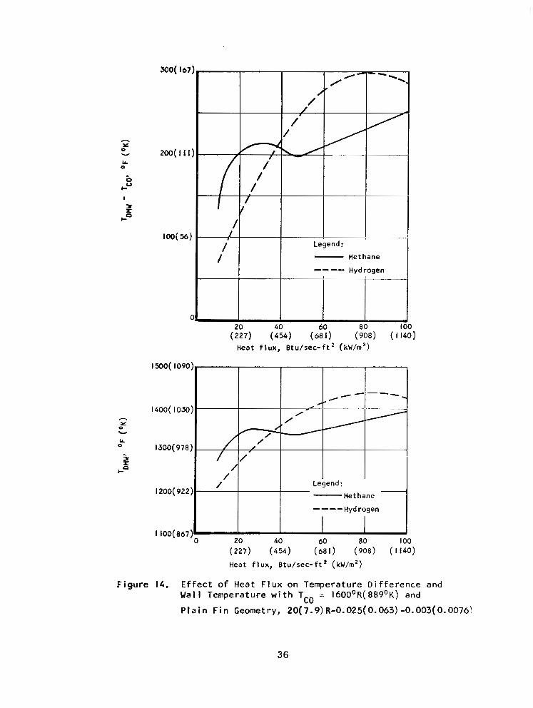
h
0 Y
v
0 LL
.. 0 V
I-
I
H e a t f l u x , B t u / s e c - f t ( k w h 2 )
0 LL
( 2 2 7 ) (454) (681) (908) ( 1140)
H e a t f l u x , B t u / s e c - f t ' ( k w h 2 )
F igure 14. Ef fec t o f Heat F lux on Temperature Difference and Wall Temperature with TCO = I60O0R( 889'K) and
P l a i n F i n Geometry, 2 0 ( 7 . 9 ) R-0.025(0.063) -0.003(0.0076\
36

400( 2 2 2 )
300( 167)
200( I I I )
loo( 56)
- 0
I500( 1090)
I400( 1030)
0 - I300( 978) 3 cl
I-
1200( 922)
(1140) ( 2 2 7 0 ) ( 3 4 1 0 ) ( 4 5 4 0 ) ( 5 6 8 0 )
Heat f lux , Btu/sec- f t ( kW/m2)
I JOO( 8 6 7 ) 0 1.0 0 200 300 400 500
( 1140) ( 2 2 7 0 ) ( 3 4 1 0 , ) ( 4 5 4 0 ) ( 5 6 8 0 )
Heat f lux , B tu /sec- f t2 (kW/m2)
F i g u r e 15. E f f e c t of Heat Flux on Temperature Difference and Wal l Temperature wi th T - 1600°R (889 'K ) and
O f f s e t F i n Geometry 20(7 .9)R0-0 .025(0 .063) -0 .003(0 .0076) c o -
37

. - .025
( .063) .ow
(. 127) (. 191)
Fin height,hfin, in. (crn)
.075
F i g u r e 16. E f f e c t o f F i n H e i g h t on Temperature D 100 Btu/sec-f t2 ( I 140 kW/m2) w i t h TCO
(889'K) and Offset F i n Geometry, 20(7
- 0.003( 0.0076)
( . 2 5 L ) * 100
i f f e r e n c e a t = 1600OF
.9) RO-h f i n
38
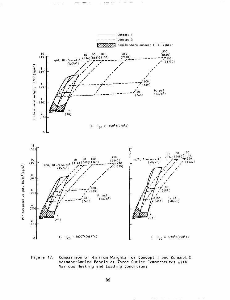
( 49 I O
h
Y - ( 2 9 L P,
Concept I
--- -- Concept 2
rwfl Region where concept I i s l i g h t e r
1 \..-,. . - """""" r"""
/ .' I /
/ /
I /
I \ " U T / , yJ .1
/ - L """ I """"" - /
1 /"- L' """""_
a . TCO = 1400°R(7780K)
-
/- /
/ /
P , ps i ( kN/rn2 )
b. TCO = 1600°R(8890K)
f 50 1- P , ps i
( 3 4 5 ) (kN/rn' )
c . TCO = 1760°R(978'K)
Figure 17. Comparison o f Minimum Weights f o r Concept I and Concept 2 Methane-Cooled Panels a t Three Outlet Temperatures with Various Heating and Loading Conditions
39

Methane
""" Hydrogen
Region where methane panels are l ighter
a . TCO = 1400'R b. TCO = 1600'R ( 7 7 8 ' K )
C . TCO = I760'R ( 8 8 9 ' K ) ( 9 7 8 ' K )
F igu re 18. Comparison o f t he Minimum Concept I Panel Weights f o r Hydrogen and Methane Coolants a t Three Out let Temperatures wi th Var ious Heat ing and Loading Cond i t ions
40

Methane -- -- - Hydrogen
a. TCO = 1400°R( 778'K)
q /A , B t u / s e c - f t 2
c . TCO = 1760°R(978'K)
F igure 19. Comparison o f t h e ninimum Concept 2 Panel Wcight for Hydrogen and Methane Coolants a t Three Out let Tcmperatucs with Various Heating and Loading Conditions
NASA-Langley, 1971 - 33 CR-1652 41
" .. .. . " . - ~ -. . " - .. . ". - ~ "" . -