Comparison of a three-dimensional numerical model for fire ...
31
Espinos A, Ibañez C, Romero ML, Hospitaler A. Comparison of a three-dimensional numerical model for fire resistance of axially loaded concrete filled steel tubular columns with Eurocode 4. Journal of Structural Fire Engineering 2011; 2(2):67-79. doi: 10.1260/2040-2317.2.2.67 1 Comparison of a three-dimensional numerical model for fire resistance of axially loaded concrete filled steel tubular columns with Eurocode 4 Ana Espinós, Carmen Ibáñez, Manuel L. Romero*, Antonio Hospitaler Instituto de Ciencia y Tecnología del Hormigón (ICITECH) Universidad Politécnica de Valencia, Camino de Vera s/n, 46022 Valencia (Spain) * [email protected] ABSTRACT In this paper, the behaviour of slender axially loaded square and circular CFT columns exposed to fire is modelled using the finite element analysis package ABAQUS. A realistic sequentially coupled nonlinear thermal-stress analysis is conducted for a series of columns available in the literature. By means of this model, a comparison between fire resistance simulations results and experimental tests found in literature is made. Similarly, simulations results are compared to the Eurocode 4 simplified calculation model predictions. Comparisons show that whereas Eurocode 4 predictions are very conservative for both circular and square section CFT columns, the results obtained from the developed numerical model are much more realistic. Keywords: Fire resistance; Concrete filled tubular column; Finite element analysis; Simple calculation model, Eurocode 4
Transcript of Comparison of a three-dimensional numerical model for fire ...

Espinos A, Ibañez C, Romero ML, Hospitaler A. Comparison of a three-dimensional numerical model for fire resistance of
axially loaded concrete filled steel tubular columns with Eurocode 4. Journal of Structural Fire Engineering 2011; 2(2):67-79.
doi: 10.1260/2040-2317.2.2.67
1
Comparison of a three-dimensional numerical model for fire resistance
of axially loaded concrete filled steel tubular columns with Eurocode 4
Ana Espinós, Carmen Ibáñez, Manuel L. Romero*, Antonio Hospitaler
Instituto de Ciencia y Tecnología del Hormigón (ICITECH)
Universidad Politécnica de Valencia, Camino de Vera s/n, 46022 Valencia (Spain)
ABSTRACT
In this paper, the behaviour of slender axially loaded square and circular CFT columns
exposed to fire is modelled using the finite element analysis package ABAQUS. A realistic
sequentially coupled nonlinear thermal-stress analysis is conducted for a series of columns
available in the literature. By means of this model, a comparison between fire resistance
simulations results and experimental tests found in literature is made. Similarly, simulations
results are compared to the Eurocode 4 simplified calculation model predictions. Comparisons
show that whereas Eurocode 4 predictions are very conservative for both circular and square
section CFT columns, the results obtained from the developed numerical model are much
more realistic.
Keywords: Fire resistance; Concrete filled tubular column; Finite element analysis; Simple
calculation model, Eurocode 4

Espinos A, Ibañez C, Romero ML, Hospitaler A. Comparison of a three-dimensional numerical model for fire resistance of
axially loaded concrete filled steel tubular columns with Eurocode 4. Journal of Structural Fire Engineering 2011; 2(2):67-79.
doi: 10.1260/2040-2317.2.2.67
2
1. INTRODUCTION
Concrete filled tubular (CFT) columns are composite members that consist of a steel
tube filled with concrete. Filling hollow steel columns with concrete is an interesting way to
improve not only the bearing capacity of the columns but also their fire resistance [1]. Surface
temperature of a hollow structural section without external protection increases quickly
during the development of a fire. On the contrary, whether the steel tube is filled with
concrete, while the steel section loses gradually its resistance and rigidity, the load is
transferred to the concrete core, that heats up more slowly, thus increasing the fire resistance
of the column.
In addition to its structural function, the steel tube acts as a radiation shield to the
concrete core, what, combined with a steam layer in the steel-concrete boundary, leads to a
lower temperature rise in the concrete core when compared to exposed reinforced concrete
structures [1].
As a consequence of the different thermal conductivities of steel and concrete, the
temperature distribution in the cross-section of a CFT column is not uniform during a fire.
This fact generates a behaviour characterized by noticeable heating transients and high
temperature differentials across the cross-section. Due to these differentials, CFT columns can
reach high fire resistance times without external fire protection [1]. However, it is necessary
to resort to numerical models in order to predict accurately these temperature profiles along
the fire exposure time [2] [3].
In this work, the finite element analysis package ABAQUS [4] was employed to model
the behaviour of slender axially loaded circular and square CFT columns exposed to fire.
With this software, a sequentially coupled nonlinear thermal-stress analysis was conducted.
The results of the simulations were compared with a series of fire resistance tests available in

Espinos A, Ibañez C, Romero ML, Hospitaler A. Comparison of a three-dimensional numerical model for fire resistance of
axially loaded concrete filled steel tubular columns with Eurocode 4. Journal of Structural Fire Engineering 2011; 2(2):67-79.
doi: 10.1260/2040-2317.2.2.67
3
the literature [5] [6] [7], as well as with the predictions of the Eurocode 4 [8] simplified
calculation model.
2. DEVELOPMENT OF THE NUMERICAL MODEL
2.1. Finite element mesh of the model
A three-dimensional numerical model was developed in ABAQUS [4], with variable
parameters such as the length of the column (L), the external size or diameter (D), the
thickness of the steel tube (t), the presence of reinforcement and the thermal and mechanical
material properties. It consisted of two or three parts: the concrete core, the steel tube and,
according to the case, the reinforcement. Due to symmetry on the geometry and boundary
conditions, only a quarter of the column was modelled.
The model was meshed with three-dimensional eight-node solid elements, for both the
concrete core and the steel tube. In the case of reinforcing bars, two-node elements were used.
The mesh density was controlled to have a maximum element size of 2 cm, what, by means of
a prior sensitivity analysis, was proved to be sufficient to predict with enough accuracy the
thermal and mechanical behaviour of the CFT columns under fire. The finite element mesh
for one of the CFT columns studied can be found in Fig. 1.
2.2. Material properties
The numerical model took into account the temperature dependent thermal and
mechanical properties of the materials. For modelling mechanical behaviour of concrete, Lie’s
model [9] was employed, provided that it proved to be the one that best predicted the
behaviour of the concrete infill in CFT columns, as said by Hong & Varma [3]. The
mechanical model implemented in ABAQUS employed the hyperbolic Drucker-Prager yield
surface. The thermal properties for concrete at elevated temperatures were extracted from EN

Espinos A, Ibañez C, Romero ML, Hospitaler A. Comparison of a three-dimensional numerical model for fire resistance of
axially loaded concrete filled steel tubular columns with Eurocode 4. Journal of Structural Fire Engineering 2011; 2(2):67-79.
doi: 10.1260/2040-2317.2.2.67
4
1992-1-2 [10]. For steel, the temperature dependent thermal and mechanical properties
recommended in EN 1993-1-2 [11]¡Error! No se encuentra el origen de la referencia. were
adopted. The isotropic multiaxial plasticity model with the Von Mises yield surface was
employed.
The constant values of the thermal expansion coefficient for concrete (c) and steel (s)
recommended by Hong and Varma [3] were employed: s = 12 x 10-6 ºC-1, c = 6 x 10⁻⁶ ºC-1.
With regard to the moisture content of the concrete infill, it is necessary to take into account
that the lower the moisture content, the less the heat spent in evaporating the water and thus
the more the heat dedicated to increase the column temperature. Therefore, columns with low
moisture contents have an earlier failure than those with a great percentage of moisture, since
they get much higher temperatures. In this research, the moisture content of the concrete infill
was not modelled, what lies on the safe side.
2.3. Thermal analysis
For conducting the thermal analysis, the standard ISO-834 [12] fire curve was applied
to the exposed surface of the CFT column model as a thermal load through the convection and
radiation heat transfer mechanisms. The thermal contact in the steel-concrete boundary was
modelled by employing the “gap conductance” and “gap radiation” options. The thermal
resistance at the boundary between the steel tube and the concrete core was modelled by
employing a constant value of 200 W/m2K for the gap conductance.
For the governing parameters of the heat transfer problem, the values recommended in
EN 1991-1-2 [13] were adopted.
Coefficient of convective heat transfer at the exposed surface: h=25 W/m2K.
Configuration factor for radiation at the exposed surface: Ф=1.
Stephan-Boltzmann constant: σ=5.67 x 10 -8 W/ m2K4.
Espinos A, Ibañez C, Romero ML, Hospitaler A. Comparison of a three-dimensional numerical model for fire resistance of
axially loaded concrete filled steel tubular columns with Eurocode 4. Journal of Structural Fire Engineering 2011; 2(2):67-79.
doi: 10.1260/2040-2317.2.2.67
5
Emissivity of the exposed surface: ε=0.7.
Emissivity of the fire: ε=1.
Initial temperature: T0=20 ºC
The three-dimensional eight-node heat transfer solid element with nodal temperature
degree of freedom DC3D8 was used to mesh the thermal model. The reinforcing bars for the
reinforced specimens were modelled using two-node heat transfer links DC1D2.
The nodal temperature-time curves resulting from the nonlinear heat transfer analysis
were subsequently applied to the mechanical model as a thermal load.
2.4. Mechanical analysis
After the thermal analysis, a nonlinear stress analysis was carried out using also
ABAQUS taking into account the nodal temperature-time curves previously calculated. The
three-dimensional eight-node solid element C3D8RT was used to mesh the concrete core and
the steel tube. These elements were thermally coupled bricks, with reduced integration and
hourglass control. For modelling the longitudinal steel bars for the reinforced specimens, two-
node T3D2 truss elements with both nodes tied to their corresponding concrete nodes were
used.
In order to model the mechanical interaction between the steel tube and concrete infill
contacting surfaces the next models were used. A “hard point” contact formulation was
employed for the normal behaviour, which allows any pressure value when the surfaces are in
contact and transmits no pressure when the surfaces do not contact. The tangent behaviour
made use of the Coulomb friction model with a constant friction coefficient of 0.3.

Espinos A, Ibañez C, Romero ML, Hospitaler A. Comparison of a three-dimensional numerical model for fire resistance of
axially loaded concrete filled steel tubular columns with Eurocode 4. Journal of Structural Fire Engineering 2011; 2(2):67-79.
doi: 10.1260/2040-2317.2.2.67
6
3. VALIDATION OF THE NUMERICAL MODEL
The three-dimensional numerical model was validated by comparing the simulations
with experimental fire resistance tests [5] [6] [7] and with the EC4 simplified calculation
model [8].
3.1. Specimens tested
a) Circular columns
The numerical model was employed to predict the standard fire behaviour of a series of
circular section CFT column specimens listed in Table 1. These specimens were tested at the
NRCC, and their results published by Lie & Caron [5]. All the specimens tested were circular,
filled with siliceous aggregate concrete and subjected to concentric compression load. Their
total length was 3810 mm, although only the central 3048 mm were directly exposed to fire.
Because of the loading conditions, all the tests were assumed as fix-ended.
b) Square columns
Following the process explained above, the fire behaviour of eight square section CFT
columns was studied by means of the numerical model developed. The characteristics of these
specimens are shown in Table 2. Four of these columns were tested at the NRCC, and their
results published by Lie & Chabot [6], and the rest of the specimens were tested by Grandjean
et al. [7]¡Error! No se encuentra el origen de la referencia. at CIDECT. In this series, all
the columns tested were square, filled with reinforced concrete and subjected to concentric
compression load. Only 3400 mm of the 3600 mm of their total length were directly exposed
to fire. As in the previous series of circular columns, the ending conditions of all the columns
were assumed as fixed.
Espinos A, Ibañez C, Romero ML, Hospitaler A. Comparison of a three-dimensional numerical model for fire resistance of
axially loaded concrete filled steel tubular columns with Eurocode 4. Journal of Structural Fire Engineering 2011; 2(2):67-79.
doi: 10.1260/2040-2317.2.2.67
7
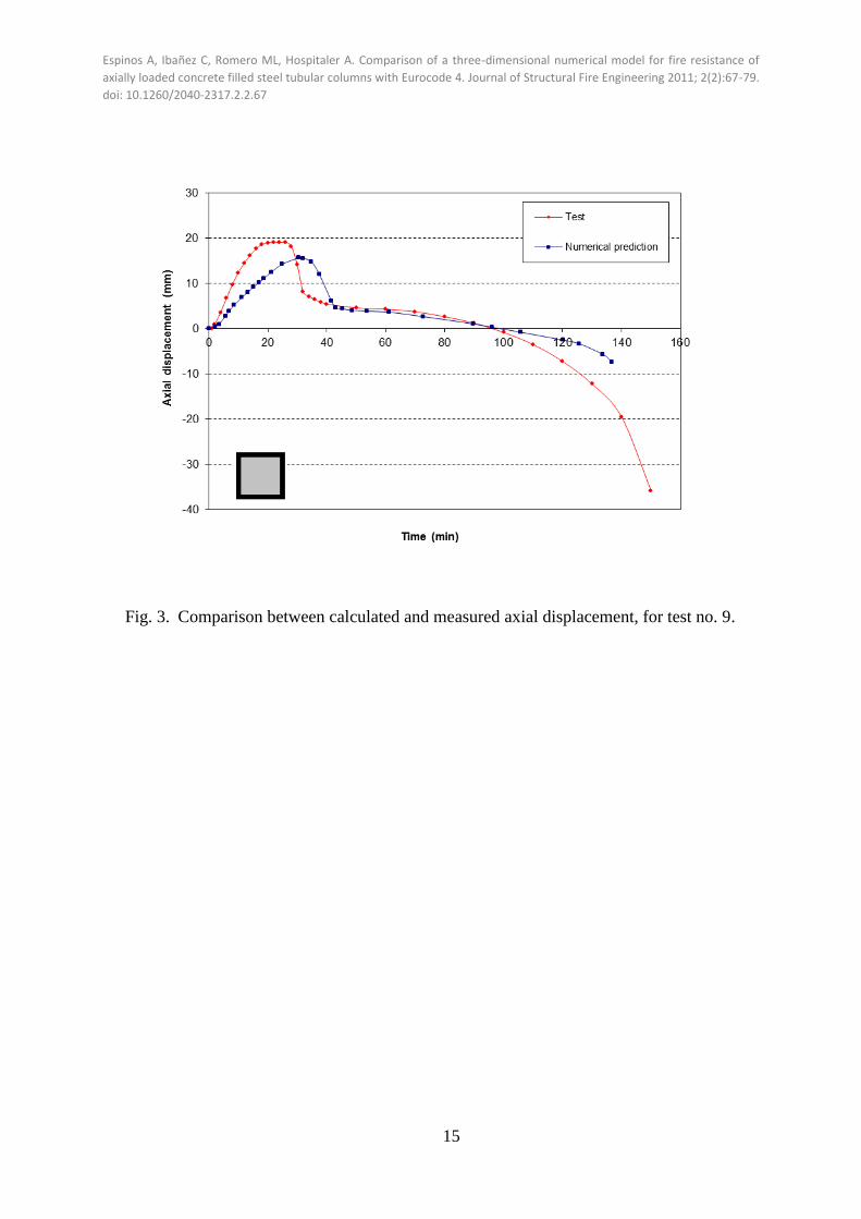
3.2. Comparison with experimental results
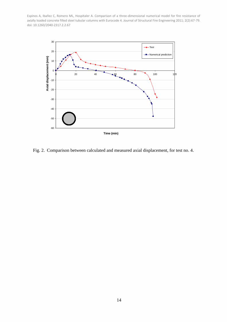
For each simulation, the axial displacement at the top of the column versus the fire
exposure time was registered, comparing this curve with the one obtained in the fire
resistance test [5] [6] [7] . Fig. 2 and Fig. 3 show an example of the comparison between both
curves for a circular and a square specimen respectively.
From these curves, the fire resistance rating (FRR) was obtained for each one of the
specimens under study. The failure criteria from EN 1363-1 [14] were adopted. This standard
establishes that the failure time is given by the most restrictive from the following two limits:
Maximum axial displacement: mm 100
hC
Maximum axial displacement velocity: mm/min 1000
3h
dt
dC
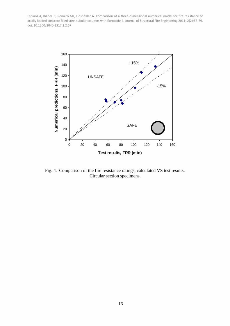
By applying these criteria, the values in Table 3 and Table 4 were obtained.
In case of circular section CFT, as it can be seen in Fig. 4, most of the values obtained
lie in the region of the 15% error, apart from two values, corresponding to columns no. 1 and
2, which have the smallest diameters.
On the other hand, for square section CFT columns, the fire resistance rating (FRR)
values are shown in Fig. 5 and again it can be seen that most of them are placed in the ±15%
region. There are only two values that lie outside these boundaries and they correspond to
specimens no. 11 and 12, which have one of the biggest size of the series studied and are
filled with concrete with a grade near 50 MPa (48.1 and 47 MPa respectively), what
corresponds to high strength concrete.
The maximum axial displacement (max) was also obtained for each column studied.
Table 3 and Table 4 show the calculated and measured values, which are plotted in Fig. 6 and
Fig. 7.

Espinos A, Ibañez C, Romero ML, Hospitaler A. Comparison of a three-dimensional numerical model for fire resistance of
axially loaded concrete filled steel tubular columns with Eurocode 4. Journal of Structural Fire Engineering 2011; 2(2):67-79.
doi: 10.1260/2040-2317.2.2.67
8
With regard to circular section CFT columns, it can be seen again that most of the cases
lie in the region of the 15% error, apart from specimens no. 3 and 8, corresponding to those
with a higher loading level, over the 20% of the maximum load bearing capacity of the
column at room temperature.
However, for square section CFT columns most of the cases are placed out of the ±15%
region, mainly in the safe side of the graph. Specimens no. 10 and 11 are those which lie more
separately from the 15% error region, corresponding again with columns of big dimensions
and filled with concrete of slightly higher grade than the rest. This fact shows that the
numerical model is not able to predict with enough accuracy the maximum axial displacement
produced in square section columns filled with reinforced concrete.
3.3. Comparison with Eurocode 4 simplified calculation model
In this section, the numerical model is compared with the predictions of the EC4
simplified calculation model [8], obtaining the results shown in Table 5 and Table 6. For both
kinds of sections, circular and square, it can be seen in Fig. 8 and Fig. 9 that the proposed
numerical model gives a better prediction of the fire resistance rating, showing a very accurate
trend.
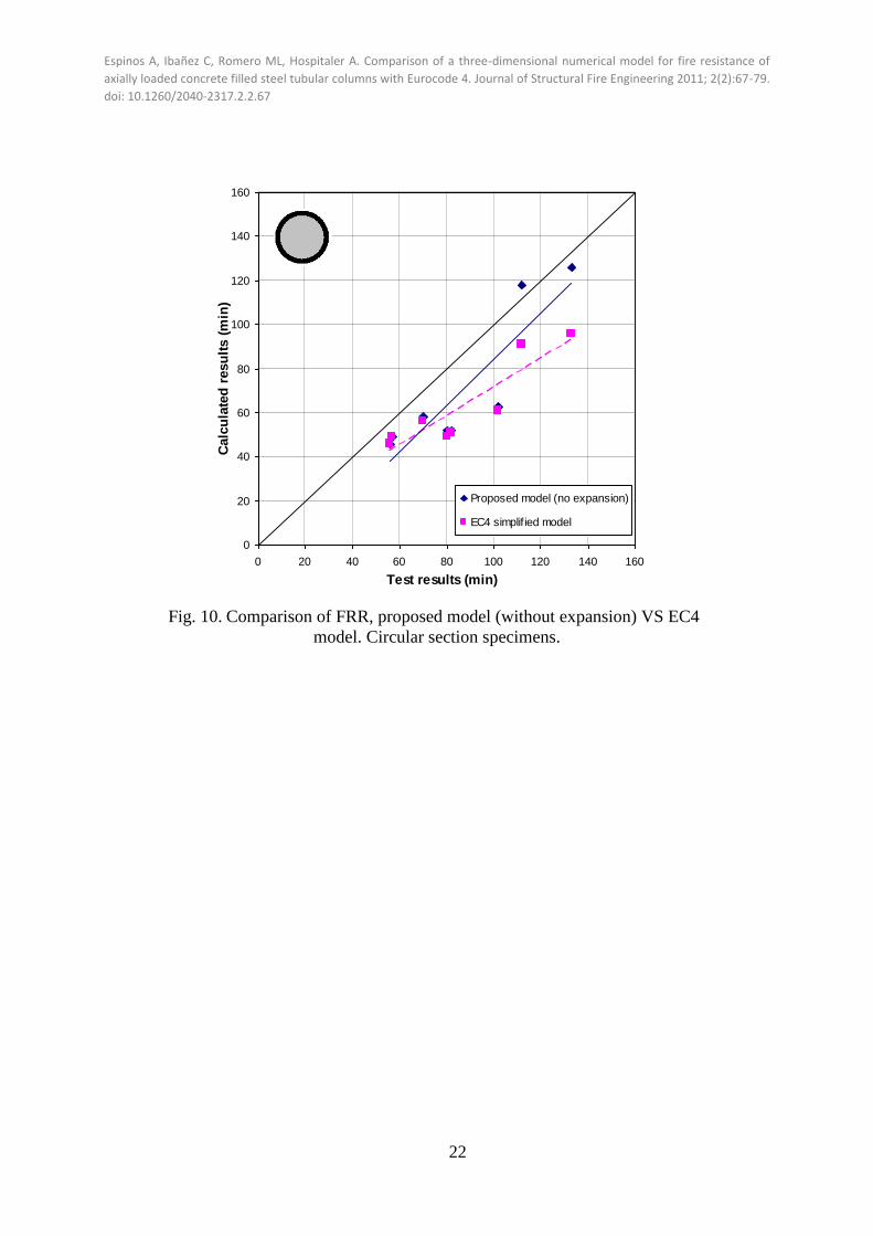
On the other hand, the EC4 simplified model turns out to be excessively conservative,
as shown in the figure. We must note that the EC4 simplified model doesn’t take into account
the thermal expansion of the materials, nor the air gap at the steel-concrete boundary, what
lies on the safe side and gives a very conservative prediction. If we apply these simplifications
to our numerical model, smaller values of the fire resistance ratings are obtained, very similar
to those predicted by EC4, as shown in Table 5 and Table 6. As it can be seen in Fig. 10 and
Fig. 11, our predicted values reproduce quite well the results of EC4.

Espinos A, Ibañez C, Romero ML, Hospitaler A. Comparison of a three-dimensional numerical model for fire resistance of
axially loaded concrete filled steel tubular columns with Eurocode 4. Journal of Structural Fire Engineering 2011; 2(2):67-79.
doi: 10.1260/2040-2317.2.2.67
9
Regarding to circular section CFT columns, values obtained applying the
simplifications above to our numerical model reproduce with high accuracy the results of
EC4, except for those tests with fire resistance ratings around 120 minutes, where our
numerical model provides more accurate results, what produces a more close to reality trend.
In the case of square section specimens, the results of fire resistance time obtained by
applying these simplifications to our numerical model are not as good as the ones
corresponding to circular section columns. However, the values predicted by our model
provide a more realistic behaviour than those obtained by applying the EC4 simplified
calculation model.
4. SUMMARY AND CONCLUSIONS
A three-dimensional numerical model for axially loaded slender circular and square
section CFT columns under fire was presented. By means of this model, the behaviour under
standard fire conditions of sixteen column specimens previously tested by the NRCC research
group [5] [6] and CIDECT [7]¡Error! No se encuentra el origen de la referencia.,
respectively, was predicted.
For circular section CFT columns, the proposed numerical model showed better
behaviour for columns with low slenderness and loading levels under 20%. Despite these two
aspects, the model shows an accurate response when contrasted with the fire tests.
For square section CFT columns with reinforcement, the numerical model developed
also provided more accurate values for specimens with low slenderness and filled with
concrete of grades lower than 40 MPa.
This study also proved that the predictions of EC4 simplified calculation model [8] can
be reproduced with the proposed numerical model by eliminating the thermal expansion of
the materials, which lies on the safe side. Nevertheless, if the real behaviour of CFT columns

Espinos A, Ibañez C, Romero ML, Hospitaler A. Comparison of a three-dimensional numerical model for fire resistance of
axially loaded concrete filled steel tubular columns with Eurocode 4. Journal of Structural Fire Engineering 2011; 2(2):67-79.
doi: 10.1260/2040-2317.2.2.67
10
under fire wants to be predicted, this aspect must be taken into account, extending the failure
time. The expansion of the steel tube produces an opposed axial strain in the early stages of
heating, as well as an opening of the gap in the steel-concrete interface, which delays the
heating of the concrete core and thus increases the fire resistance rating.
The proposed numerical model proved to give better predictions than the EC4
simplified model, which turned out to be excessively conservative for both circular and square
section specimens.
ACKNOWLEDGEMENTS
The authors express their sincere gratitude to the Spanish “Ministerio de Ciencia e
Innovación” for the help provided through the Project BIA2009-9411 and to the European
Union through the FEDER funds.
REFERENCES
[1] CIDECT. Twilt L, Hass R, Klingsch W, Edwards M, Dutta D. Design guide for structural
hollow section columns exposed to fire. CIDECT (Comité International pour le
Développement et l'Etude de la Construction Tubulaire). Cologne, Germany: Verlag
TÜV Rheinland; 1996.
[2] Ding J, Wang YC. Realistic modelling of thermal and structural behaviour of unprotected
concrete filled tubular columns in fire. Journal of Constructional Steel Research 2008;
64:1086-1102.
[3] Hong S, Varma AH. Analytical modeling of the standard fire behaviour of loaded CFT
columns. Journal of Constructional Steel Research 2009; 65:54-69.
[4] ABAQUS. ABAQUS/Standard Version 6.6 User’s Manual: Volumes I-III. Pawtucket,
Rhode Island: Hibbit, Karlsson & Sorenson, Inc.; 2005.

Espinos A, Ibañez C, Romero ML, Hospitaler A. Comparison of a three-dimensional numerical model for fire resistance of
axially loaded concrete filled steel tubular columns with Eurocode 4. Journal of Structural Fire Engineering 2011; 2(2):67-79.
doi: 10.1260/2040-2317.2.2.67
11
[5] Lie TT, Caron SE. Fire resistance of circular hollow steel columns filled with siliceous
aggregate concrete: Test results. Internal report No. 570. Ottawa, Canada: Institute for
Research in Construction, National Research Council of Canada; 1988.
[6] Lie TT, Chabot M. Experimental studies on the fire resistance of hollow steel columns
filled with bar-reinforced concrete. Internal report No. 628. Ottawa, Canada: Institute for
Research in Construction, National Research Council of Canada; 1992.
[7] Grandjean G, Grimault JP, Petit L. Determination de la duree au feu des profiles creux
remplis de beton. Convention Nº7210 SA/3/302. Resport CIDECT 15B. 1972.
[8] CEN (European Committee for Standardisation). EN 1994-1-2, Eurocode 4: Design of
composite steel and concrete structures, Part 1.2: General rules - Structural fire design.
Brussels: CEN; 2005.
[9] Lie TT. Fire resistance of circular steel columns filled with bar-reinforced concrete.
Journal of Structural Engineering-ASCE 1994; 120(5):1489-1509.
[10] CEN (European Committee for Standardisation). EN 1992-1-2, Eurocode 2: Design of
concrete structures, Part 1.2: General rules – Structural fire design. Brussels: CEN; 2004.
[11] CEN (European Committee for Standardisation). EN 1993-1-2, Eurocode 3: Design of
steel structures, Part 1.2: General rules – Structural fire design. Brussels: CEN; 2005.
[12] ISO (International Standards Organization). ISO 834: Fire resistance tests, elements of
building construction. Switzerland: International Standards Organisation; 1980.
[13] CEN (European Committee for Standardisation). EN 1991-1-2, Eurocode 1: Actions on
structures, Part 1.2: General actions - Actions on structures exposed to fire. Brussels:
CEN; 2002.
[14] EN (European Committee for Standardisation). EN 1363-1: Fire resistance tests. Part 1:
General requirements. Brussels: CEN; 1999.

Espinos A, Ibañez C, Romero ML, Hospitaler A. Comparison of a three-dimensional numerical model for fire resistance of
axially loaded concrete filled steel tubular columns with Eurocode 4. Journal of Structural Fire Engineering 2011; 2(2):67-79.
doi: 10.1260/2040-2317.2.2.67
12

Espinos A, Ibañez C, Romero ML, Hospitaler A. Comparison of a three-dimensional numerical model for fire resistance of
axially loaded concrete filled steel tubular columns with Eurocode 4. Journal of Structural Fire Engineering 2011; 2(2):67-79.
doi: 10.1260/2040-2317.2.2.67
13
Fig. 1. Three-dimensional finite element model for CFT columns..
Espinos A, Ibañez C, Romero ML, Hospitaler A. Comparison of a three-dimensional numerical model for fire resistance of
axially loaded concrete filled steel tubular columns with Eurocode 4. Journal of Structural Fire Engineering 2011; 2(2):67-79.
doi: 10.1260/2040-2317.2.2.67
14
-60
-50
-40
-30
-20
-10
0
10
20
30
0 20 40 60 80 100 120
Time (min)
Ax
ial d
isp
lac
em
en
t (m
m)
Test
Numerical prediction
Fig. 2. Comparison between calculated and measured axial displacement, for test no. 4.
Espinos A, Ibañez C, Romero ML, Hospitaler A. Comparison of a three-dimensional numerical model for fire resistance of
axially loaded concrete filled steel tubular columns with Eurocode 4. Journal of Structural Fire Engineering 2011; 2(2):67-79.
doi: 10.1260/2040-2317.2.2.67
15
Fig. 3. Comparison between calculated and measured axial displacement, for test no. 9.
Espinos A, Ibañez C, Romero ML, Hospitaler A. Comparison of a three-dimensional numerical model for fire resistance of
axially loaded concrete filled steel tubular columns with Eurocode 4. Journal of Structural Fire Engineering 2011; 2(2):67-79.
doi: 10.1260/2040-2317.2.2.67
16
0
20
40
60
80
100
120
140
160
0 20 40 60 80 100 120 140 160
Test results, FRR (min)
Nu
meri
cal
pre
dic
tio
ns,
FR
R (
min
)
+15%
-15%
SAFE
Fig. 4. Comparison of the fire resistance ratings, calculated VS test results.
Circular section specimens.
UNSAFE

Espinos A, Ibañez C, Romero ML, Hospitaler A. Comparison of a three-dimensional numerical model for fire resistance of
axially loaded concrete filled steel tubular columns with Eurocode 4. Journal of Structural Fire Engineering 2011; 2(2):67-79.
doi: 10.1260/2040-2317.2.2.67
17
Fig. 5. Comparison of the fire resistance ratings, calculated VS test results.
Square section specimens.
+15%
-15%
SAFE
UNSAFE

Espinos A, Ibañez C, Romero ML, Hospitaler A. Comparison of a three-dimensional numerical model for fire resistance of
axially loaded concrete filled steel tubular columns with Eurocode 4. Journal of Structural Fire Engineering 2011; 2(2):67-79.
doi: 10.1260/2040-2317.2.2.67
18
0
5
10
15
20
25
0 5 10 15 20 25
Test results, max (mm)
Nu
meri
cal
pre
dic
tio
ns, m
ax (
mm
)
+15%
-15%
Fig. 6. Comparison of the maximum axial displacement, calculated VS test
results. Circular section specimens.

Espinos A, Ibañez C, Romero ML, Hospitaler A. Comparison of a three-dimensional numerical model for fire resistance of
axially loaded concrete filled steel tubular columns with Eurocode 4. Journal of Structural Fire Engineering 2011; 2(2):67-79.
doi: 10.1260/2040-2317.2.2.67
19
Fig. 7. Comparison of the maximum axial displacement, calculated VS test results.
Square section specimens.
+15%
-15%

Espinos A, Ibañez C, Romero ML, Hospitaler A. Comparison of a three-dimensional numerical model for fire resistance of
axially loaded concrete filled steel tubular columns with Eurocode 4. Journal of Structural Fire Engineering 2011; 2(2):67-79.
doi: 10.1260/2040-2317.2.2.67
20
0
20
40
60
80
100
120
140
160
0 20 40 60 80 100 120 140 160
Test results (min)
Calc
ula
ted
resu
lts (
min
)
Proposed model
EC4 simplif ied model
Fig. 8. Comparison of FRR, proposed numerical model VS EC4 model.
Circular section specimens.

Espinos A, Ibañez C, Romero ML, Hospitaler A. Comparison of a three-dimensional numerical model for fire resistance of
axially loaded concrete filled steel tubular columns with Eurocode 4. Journal of Structural Fire Engineering 2011; 2(2):67-79.
doi: 10.1260/2040-2317.2.2.67
21
Fig. 9. Comparison of FRR, proposed numerical model VS EC4 model. Square
section specimens.
Espinos A, Ibañez C, Romero ML, Hospitaler A. Comparison of a three-dimensional numerical model for fire resistance of
axially loaded concrete filled steel tubular columns with Eurocode 4. Journal of Structural Fire Engineering 2011; 2(2):67-79.
doi: 10.1260/2040-2317.2.2.67
22
0
20
40
60
80
100
120
140
160
0 20 40 60 80 100 120 140 160
Test results (min)
Calc
ula
ted
resu
lts (
min
)
Proposed model (no expansion)
EC4 simplif ied model
Fig. 10. Comparison of FRR, proposed model (without expansion) VS EC4
model. Circular section specimens.

Espinos A, Ibañez C, Romero ML, Hospitaler A. Comparison of a three-dimensional numerical model for fire resistance of
axially loaded concrete filled steel tubular columns with Eurocode 4. Journal of Structural Fire Engineering 2011; 2(2):67-79.
doi: 10.1260/2040-2317.2.2.67
23
Fig. 11. Comparison of FRR, proposed model (without expansion) VS EC4 model.
Square section specimens.

Espinos A, Ibañez C, Romero ML, Hospitaler A. Comparison of a three-dimensional numerical model for fire resistance of
axially loaded concrete filled steel tubular columns with Eurocode 4. Journal of Structural Fire Engineering 2011; 2(2):67-79.
doi: 10.1260/2040-2317.2.2.67
24
Table 1. List of circular section CFT columns analyzed from the NRCC research report [5]
Column
specimen D (mm) t (mm)
fy
(N/mm2) fck (N/mm2)
N
(kN) = N / Npl,Rd
FRR
(min)
1 141 6.5 401.93 28.62 131 8.90% 57
2 168 4.8 346.98 28.62 218 15.37% 56
3 219 4.8 322.06 24.34 492 26.19% 80
4 219 4.8 322.06 24.34 384 20.44% 102
5 219 8.2 367.43 24.34 525 18.88% 82
6 273 5.6 412.79 26.34 574 17.08% 112
7 273 5.6 412.79 26.34 525 15.63% 133
8 273 5.6 412.79 26.34 1000 29.76% 70

Espinos A, Ibañez C, Romero ML, Hospitaler A. Comparison of a three-dimensional numerical model for fire resistance of
axially loaded concrete filled steel tubular columns with Eurocode 4. Journal of Structural Fire Engineering 2011; 2(2):67-79.
doi: 10.1260/2040-2317.2.2.67
25
Table 2. List of square section CFT columns analyzed from the NRCC research report [6]
and the CIDECT [7].
Column
specimen
D
(mm)
t
(mm) Reinforcement
fs
(N/mm2)
fy
(N/mm2)
fck
(N/mm2)
N
(kN) = N / Npl.Rd
FRR
(min) ORIGIN
9 203.2 6.35 416 350 400 37.8 500 13.26% 150 NRCC
10 203.2 6.35 416 350 400 47 930 24.67% 105 NRCC
11 254 6.35 419.5 350 400 48.1 1440 26.28% 113 NRCC
12 254 6.35 419.5 350 400 47 2200 40.15% 70 NRCC
13 140 3.6 48 388 388 41.258 410 26.06% 46 CIDECT
14 160 3.6 410+48 380 380 35.28 540 28.62% 61 CIDECT
15 225 3.6 410+412 355 355 35.966 1550 49.28% 60 CIDECT
16 260 6.3 414+414 370 370 32.34 1500 32.91% 109 CIDECT

Espinos A, Ibañez C, Romero ML, Hospitaler A. Comparison of a three-dimensional numerical model for fire resistance of
axially loaded concrete filled steel tubular columns with Eurocode 4. Journal of Structural Fire Engineering 2011; 2(2):67-79.
doi: 10.1260/2040-2317.2.2.67
26
Table 3. Predicted and measured FRR and maximum axial displacement (max). Circular
section specimens.
Column
specimen
FRR (min)
NS
test
FRR
FRRFRR max (mm)
NS
test
max,
max,
max
Test Simulation Test Simulation
1 57 72 0.79 24.09 24.35 0.99
2 56 75 0.75 20.48 19.25 1.06
3 80 74 1.08 18.13 12.36 1.47
4 102 97 1.05 18.77 16.23 1.16
5 82 68 1.21 20.36 19.30 1.05
6 112 126 0.89 16.40 17.71 0.93
7 133 137 0.97 19.67 18.61 1.06
8 70 70 1.00 5.51 10.35 0.53
Average 0.97 Average 1.03
Standard deviation 0.15 Standard deviation 0.26

Espinos A, Ibañez C, Romero ML, Hospitaler A. Comparison of a three-dimensional numerical model for fire resistance of
axially loaded concrete filled steel tubular columns with Eurocode 4. Journal of Structural Fire Engineering 2011; 2(2):67-79.
doi: 10.1260/2040-2317.2.2.67
27
Table 4. Predicted and measured FRR and maximum axial displacement (max). Square
section specimens.
Column
specimen
FRR (min)
max (mm) Test Simulation Test Simulation
9 150 136 1.10 19.08 15.65 1.22
10 105 95 1.11 14.98 7.92 1.89
11 113 167 0.68 12.82 4.23 3.03
12 70 148 0.47 2.97 3.18 0.93
13 46 40 1.15 7.8 4.8 1.63
14 61 46 1.33 5.7 4.43 1.29
15 60 75 0.80 No data 2.29 No data
16 109 136 0.80 9.5 6.41 1.48
Average 0.93 Average 1.64
Standard deviation 0.27 Standard deviation 0.69
NS
test
max,
max,
max
NS
test
FRR
FRRFRR

Espinos A, Ibañez C, Romero ML, Hospitaler A. Comparison of a three-dimensional numerical model for fire resistance of
axially loaded concrete filled steel tubular columns with Eurocode 4. Journal of Structural Fire Engineering 2011; 2(2):67-79.
doi: 10.1260/2040-2317.2.2.67
28
Table 5. Comparison of the numerical model and EC4 predictions with the tests. Circular
section specimens.
Column
specimen
FRR (min) calc
test
FRR
FRRFRR
Test Simulation Simulation
(no expansion) EC4 Simulation
Simulation
(no expansion) EC4
1 57 72 49 49 0.79 1.16 1.16
2 56 75 46 46 0.75 1.22 1.22
3 80 74 52 49 1.08 1.54 1.63
4 102 97 63 61 1.05 1.62 1.67
5 82 68 52 51 1.21 1.58 1.61
6 112 126 118 91 0.89 0.95 1.23
7 133 137 126 96 0.97 1.06 1.39
8 70 70 58 56 1.00 1.21 1.25
Average 0.97 1.29 1.39
Standard deviation 0.15 0.25 0.21

Espinos A, Ibañez C, Romero ML, Hospitaler A. Comparison of a three-dimensional numerical model for fire resistance of
axially loaded concrete filled steel tubular columns with Eurocode 4. Journal of Structural Fire Engineering 2011; 2(2):67-79.
doi: 10.1260/2040-2317.2.2.67
29
Table 6. Comparison of the numerical model and EC4 predictions with the tests. Square
section specimens.
Column
specimen
FRR (min)
Test Simulation Simulation
EC4 Simulation Simulation
EC4 (no expansion) (no expansion)
9 150 136 128 70 1.10 1.17 2.14
10 105 95 94 41 1.11 1.12 2.56
11 113 167 138 66 0.68 0.82 1.71
12 70 148 95 37 0.47 0.74 1.89
13 46 40 38 27 1.15 1.21 1.70
14 61 46 42 29 1.33 1.45 2.10
15 60 75 66 26 0.80 0.91 2.31
16 109 136 131 44 0.80 0.83 2.48
Average 0.93 1.03 2.11
Standard deviation 0.29 0.25 0.33
calc
test
FRR
FRRFRR
Espinos A, Ibañez C, Romero ML, Hospitaler A. Comparison of a three-dimensional numerical model for fire resistance of
axially loaded concrete filled steel tubular columns with Eurocode 4. Journal of Structural Fire Engineering 2011; 2(2):67-79.
doi: 10.1260/2040-2317.2.2.67
30
LIST OF FIGURE CAPTIONS
Fig. 1. Three-dimensional finite element model for CFT columns..
Fig. 2. Comparison between calculated and measured axial displacement, for test no. 4.
Fig. 3. Comparison between calculated and measured axial displacement, for test no. 9.
Fig. 4. Comparison of the fire resistance ratings, calculated VS test results. Circular
section specimens.
Fig. 5. Comparison of the fire resistance ratings, calculated VS test results. Square
section specimens.
Fig. 6. Comparison of the maximum axial displacement, calculated VS test results.
Circular section specimens.
Fig. 7. Comparison of the maximum axial displacement, calculated VS test results.
Square section specimens.
Fig. 8. Comparison of FRR, proposed numerical model VS EC4 model. Circular section
specimens.
Fig. 9. Comparison of FRR, proposed numerical model VS EC4 model. Square section
specimens.
Fig. 10. Comparison of FRR, proposed model (without expansion) VS EC4 model.
Circular section specimens.
Fig. 11. Comparison of FRR, proposed model (without expansion) VS EC4 model. Square
section specimens.
Espinos A, Ibañez C, Romero ML, Hospitaler A. Comparison of a three-dimensional numerical model for fire resistance of
axially loaded concrete filled steel tubular columns with Eurocode 4. Journal of Structural Fire Engineering 2011; 2(2):67-79.
doi: 10.1260/2040-2317.2.2.67
31
LIST OF TABLE CAPTIONS
Table 1. List of circular section CFT columns analyzed from the NRCC research report [5]
Table 2. List of square section CFT columns analyzed from the NRCC research report [6]
and the CIDECT [7].
Table 3. Predicted and measured FRR and maximum axial displacement (max). Circular
section specimens.
Table 4. Predicted and measured FRR and maximum axial displacement (max). Square
section specimens.
Table 5. Comparison of the numerical model and EC4 predictions with the tests. Circular
section specimens.
Table 6. Comparison of the numerical model and EC4 predictions with the tests. Square
section specimens.