COMPARISON BETWEEN TWO OPTIMIZATION PROCEDURES … · The SAP2000 computer program has been used...
11
1 COMPARISON BETWEEN TWO OPTIMIZATION PROCEDURES FOR DAMPER LOCATION IN STEEL FRAME STRUCTURES Aleksandra Bogdanovic 1 , Zoran T. Rakicevic 2 and Dejan Filipovski 3 ABSTRACT The passive structural control of seismic behaviour of structures represents very practical concept and it is a qualitative change of the practice for design and construction of seismically resistant structures. Although this technology has been proven, both analytically and practically, to be very effective unfortunately still it is not accepted by the national latest codes for earthquake resistant design of structures, even in the high developed countries. Numerous different passive devices have been developed, however practical procedures for optimum design, as well as, optimization procedures and algorithms for their implementation in the structures are still modest. Pre-stressed Damping Device (PDD) compounded of a spring and piston in a closed (not hermetically) container filled with a special mixture of a silicone gel has been developed by GERB Company from Germany. Prototypes of this device in several different configurations on hypothetical 5 story steel frame structure have been tested on the 5DOF 5.0m x 5.0 m MTS shake table in Dynamic Testing Laboratory at Institute of Earthquake Engineering and Engineering Seismology (IZIIS), in Skopje, Republic of Macedonia. In order to estimate the efficiency of the developed PDDs in controlling the structural response due to seismic excitations, and further to develop a procedure for optimal design and placement of these and similar devices in the process of earthquake resistant design of structures appropriate research program in three phases has been realized. For the purpose of determination of optimal location of PDDs a new hypothetical 3D 5 story, (four 3 bay frames bays in each direction in plane, x and y), steel frame structure have been designed according to the Eurocode 3 and Eurocode 8 requirements. Two optimization methods using two different fitness functions have been used. Nine initials configurations previously defined are used as a starting point in the process of optimization. Optimization procedure is based upon genetic algorithms and for the first method the desired performance is defined using derivate fitness function combined from inter-story drifts and dissipated energy by PDDs vs input energy in two directions x and y. For the second method derivate fitness function is defined from inter story drifts only. The value of fitness function is used to rank and quantifies the optimality of the particular solution among the all other solution in the process of the optimization in both methods. The effectiveness of the proposed optimization procedures will be quantified with reference to the response of the designed structure subjected to earthquake excitation. 1 Research Assistant, Institute of Earthquake Engineering and Engineering Seismology (IZIIS) ,Skopje, [email protected] 2 Professor, Institute of Earthquake Engineering and Engineering Seismology (IZIIS) ,Skopje, [email protected] 3 Junior Research, Institute of Earthquake Engineering and Engineering Seismology (IZIIS) ,Skopje, [email protected]
Transcript of COMPARISON BETWEEN TWO OPTIMIZATION PROCEDURES … · The SAP2000 computer program has been used...
1
COMPARISON BETWEEN TWO OPTIMIZATION PROCEDURES FOR DAMPER LOCATION IN STEEL FRAME STRUCTURES
Aleksandra Bogdanovic1, Zoran T. Rakicevic2 and Dejan Filipovski3
ABSTRACT
The passive structural control of seismic behaviour of structures represents very practical concept and it is a qualitative change of the practice for design and construction of seismically resistant structures. Although this technology has been proven, both analytically and practically, to be very effective unfortunately still it is not accepted by the national latest codes for earthquake resistant design of structures, even in the high developed countries. Numerous different passive devices have been developed, however practical procedures for optimum design, as well as, optimization procedures and algorithms for their implementation in the structures are still modest. Pre-stressed Damping Device (PDD) compounded of a spring and piston in a closed (not hermetically) container filled with a special mixture of a silicone gel has been developed by GERB Company from Germany. Prototypes of this device in several different configurations on hypothetical 5 story steel frame structure have been tested on the 5DOF 5.0m x 5.0 m MTS shake table in Dynamic Testing Laboratory at Institute of Earthquake Engineering and Engineering Seismology (IZIIS), in Skopje, Republic of Macedonia. In order to estimate the efficiency of the developed PDDs in controlling the structural response due to seismic excitations, and further to develop a procedure for optimal design and placement of these and similar devices in the process of earthquake resistant design of structures appropriate research program in three phases has been realized. For the purpose of determination of optimal location of PDDs a new hypothetical 3D 5 story, (four 3 bay frames bays in each direction in plane, x and y), steel frame structure have been designed according to the Eurocode 3 and Eurocode 8 requirements. Two optimization methods using two different fitness functions have been used. Nine initials configurations previously defined are used as a starting point in the process of optimization. Optimization procedure is based upon genetic algorithms and for the first method the desired performance is defined using derivate fitness function combined from inter-story drifts and dissipated energy by PDDs vs input energy in two directions x and y. For the second method derivate fitness function is defined from inter story drifts only. The value of fitness function is used to rank and quantifies the optimality of the particular solution among the all other solution in the process of the optimization in both methods. The effectiveness of the proposed optimization procedures will be quantified with reference to the response of the designed structure subjected to earthquake excitation.
1 Research Assistant, Institute of Earthquake Engineering and Engineering Seismology (IZIIS) ,Skopje, [email protected] 2 Professor, Institute of Earthquake Engineering and Engineering Seismology (IZIIS) ,Skopje, [email protected] 3 Junior Research, Institute of Earthquake Engineering and Engineering Seismology (IZIIS) ,Skopje, [email protected]
2
INTRODUCTION
The behaviour of structural systems when responding to dynamic loads is mainly associated with their ability to dissipate the kinetic and the potential energy through hysteretic and viscous mechanisms of the structures. Vibration of structures and associate forces could be reduced and controlled through damping of the structure. The damping compensates for structural nonlinearity with dissipating or absorbing the external energy. Also, the effect of damping has influence on the vulnerability of the structure particularly that of the non-structural elements, which means that the overall cost for retrofitting is also decreased.
In general, the damping in steel structures consists of inherent-viscous damping, which is usually low (1%-3% of critical), hysteretic damping through nonlinear behaviour of structural elements and damping as a result of added different energy dissipation systems.
According to Eurocode 8 (EC8) requirements, earthquake resistant steel buildings shall be designed in accordance with two concepts: a) low-dissipative structural behaviour and b) dissipative structural behaviour. In concept “a”, the action effects may be calculated based on an elastic global analysis without taking into account significant non-linear material behaviour and this concept is recommended for designing of steel structures in low seismicity regions. In concept “b” the capability of parts of the structure, so called “dissipative zones”, to resist earthquake actions through inelastic behaviour is taken into account. Structures designed in accordance with this concept belongs to structural ductility classes medium or high, which correspond to increased ability of the structure to dissipate energy through plastic mechanisms of the main structural elements.
Contrary to this approach, the other concept is based on minimizing the amount of hysteretic energy dissipated by the structure through introduction of additional damping into the structure. Possibility of introduction of additional energy dissipating mechanisms into the structure, either passive or semi-active, designed to consume a portion of the input energy reduces the damage to the main structure caused by hysteretic dissipation. What should be the total damping capacity of these devices, their contribution in the overall effective damping of the structure, their optimal number and position in order to meet the standard’s design requirements represents a crucial question.
For the purpose of determination of optimal location of Pre-stressed Damping Devices (PDDs) a new hypothetical 3D 5 story, (four 3 bay frames bays in each direction in plane), steel frame structure have been designed according to the Eurocode 3 and Eurocode 8 requirements. Theoretical approach for optimization in the nonlinear domain is very complex process especially if it is concerned and analysed on the 3D structure. The optimization procedure uses genetic algorithm and derivate fitness function for the steel structure with PDDs previously tested on the shaking table in IZIIS.
In this paper a selected part of the results are presented by which the efficiency of optimization procedures and placement of the PDDs is demonstrated in terms of providing reduction of storey acceleration, displacements, storey drifts as well as stress-strain relations for the appearance of plastic hinges when the capacity of the elements is reached. For that purpose two optimization methods using two different fitness functions have been used. For the first method the desired performance is defined using derivate fitness function combined from inter-story drifts and dissipated energy by PDDs vs input energy in two directions x and y and for the second method derivate fitness function is defined from inter story drifts only. Nine initials configurations previously defined are used as a starting point in the process of optimization.
Both methods for optimization are confirmed and quantified to the response of designed structure subjected earthquake.
A.Bogdanovic, Z.T.Rakicevic, D.Filipovski 3
DESIGN AND ANALYTICAL MODELING OF THE STRUCTURE FOR THE OPTIMIZATION PROCESS
The steel frame structure , with three bays in two directions (X and Y), have been designed as Moment Resisting Frame (MRF) according to EC8 and EC3 requirements for ultimate limit states and serviceability limit states, taking into account design response spectrum calculated for soil type B, PGA=0.28g (in two directions), damping of 2% and behaviour factor q=4. The bay length in Y direction is 6.0m while in X direction is 4.0m and storey height is 3.0 m.
The SAP2000 computer program has been used for modelling and optimizing of the structural sections during the design phase and preliminary linear response history analysis only. Beams and columns are modelled as frame elements with specified end length offsets and rigid-end factors, typically taken as 0.7.
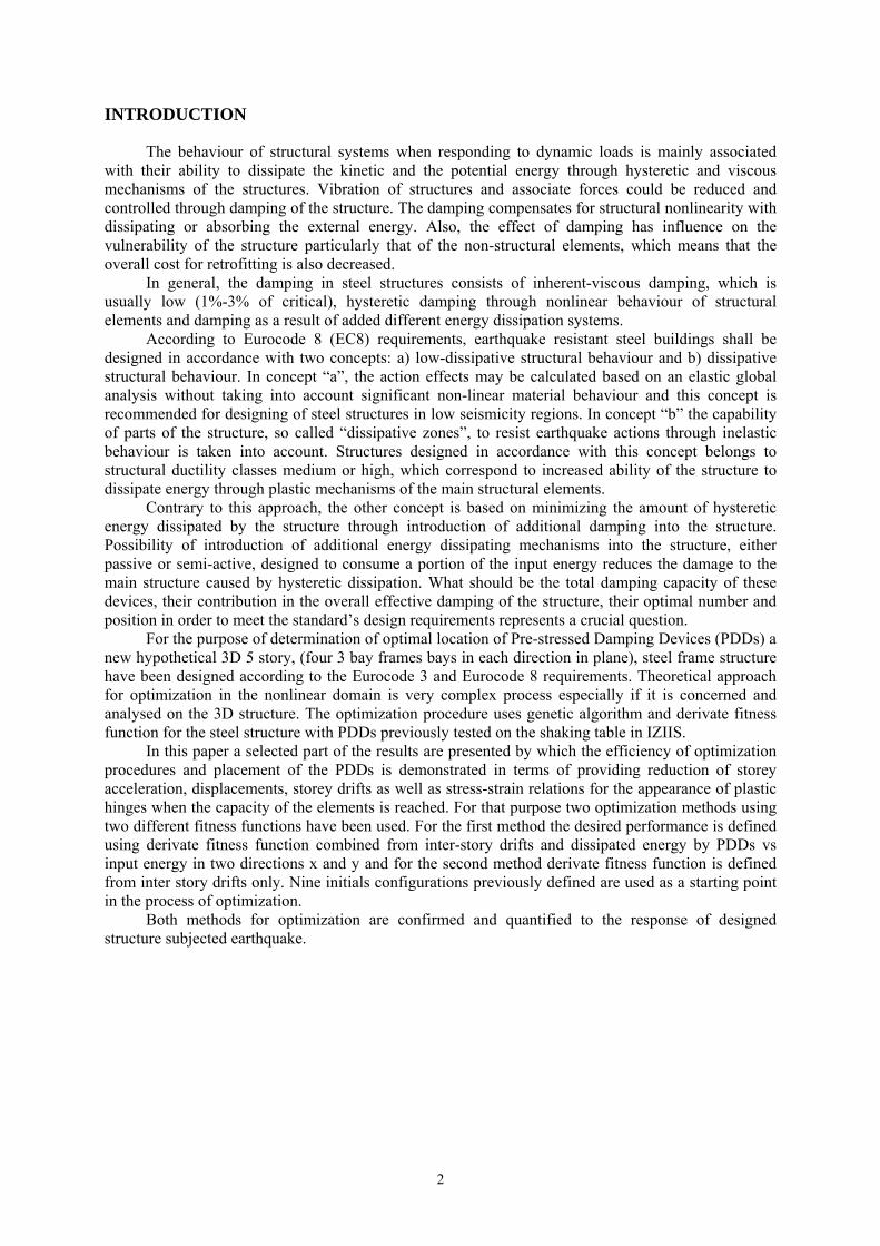
Modelling and analysis of the designed steel frame structures for the purpose of non-linear response history analysis was done using computer program Ansys12.1. (Figure1). The steel frame structure was designed as 3D structures, using several types of elements available in ANSYS12.1 program. Columns and girders are modelled using beam188 element based on Timoshenko beam theory which is a first-order shear-deformation theory: transverse-shear strain is constant through the cross-section. The element is linear two-node beam element in 3-D with six degrees of freedom at each node. These include translations in the x, y, and z directions and rotations about the x, y, and z directions. Section is taken as rigid (classical beam theory). Shape functions along the length are linear.
Figure 1. Mathematical model of 3D structure in ANSYS
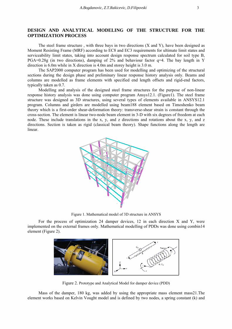
For the process of optimization 24 damper devices, 12 in each direction X and Y, were implemented on the external frames only. Mathematical modelling of PDDs was done using combin14 element (Figure 2).
Figure 2. Prototype and Analytical Model for damper device (PDD)
Mass of the damper, 180 kg, was added by using the appropriate mass element mass21.The element works based on Kelvin Vought model and is defined by two nodes, a spring constant (k) and
4
damping coefficients ( )1 and ( )2. The damping portion of the element contributes only damping coefficients to the structural damping matrix. The damping force (F) is computed with equitation given bellow: / (1) where = ( )1 + ( )2 is damping coefficient and is a velocity calculated in the previous step. Because the PDDs were pre-stressed with a force of 150 KN (same as the experimental tested PDDs) a preload in the spring as a compression is specified through an initial force (IFORCE) input in the combin14 element. In the process of optimization for the PDDs the following characteristics have been used: stiffness of the spring K=5000kN/m, =2000 kNs/m and pre-stress force F=150kN. With PDDs having these characteristics 11% of additional damping has been introduced into the structure.
OPTIMAL DISTRIBUTION USING GENETIC ALGHORITHM
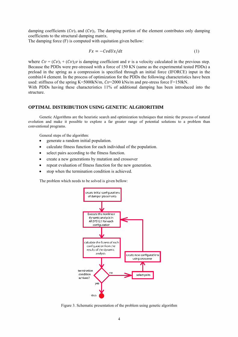
Genetic Algorithms are the heuristic search and optimization techniques that mimic the process of natural evolution and make it possible to explore a far greater range of potential solutions to a problem than conventional programs.
General steps of the algorithm: generate a random initial population.
calculate fitness function for each individual of the population.
select pairs according to the fitness function.
create a new generations by mutation and crossover
repeat evaluation of fitness function for the new generation.
stop when the termination condition is achieved.
The problem which needs to be solved is given bellow:
Figure 3. Schematic presentation of the problem using genetic algorithm
A.Bogdanovic, Z.T.Rakicevic, D.Filipovski 5
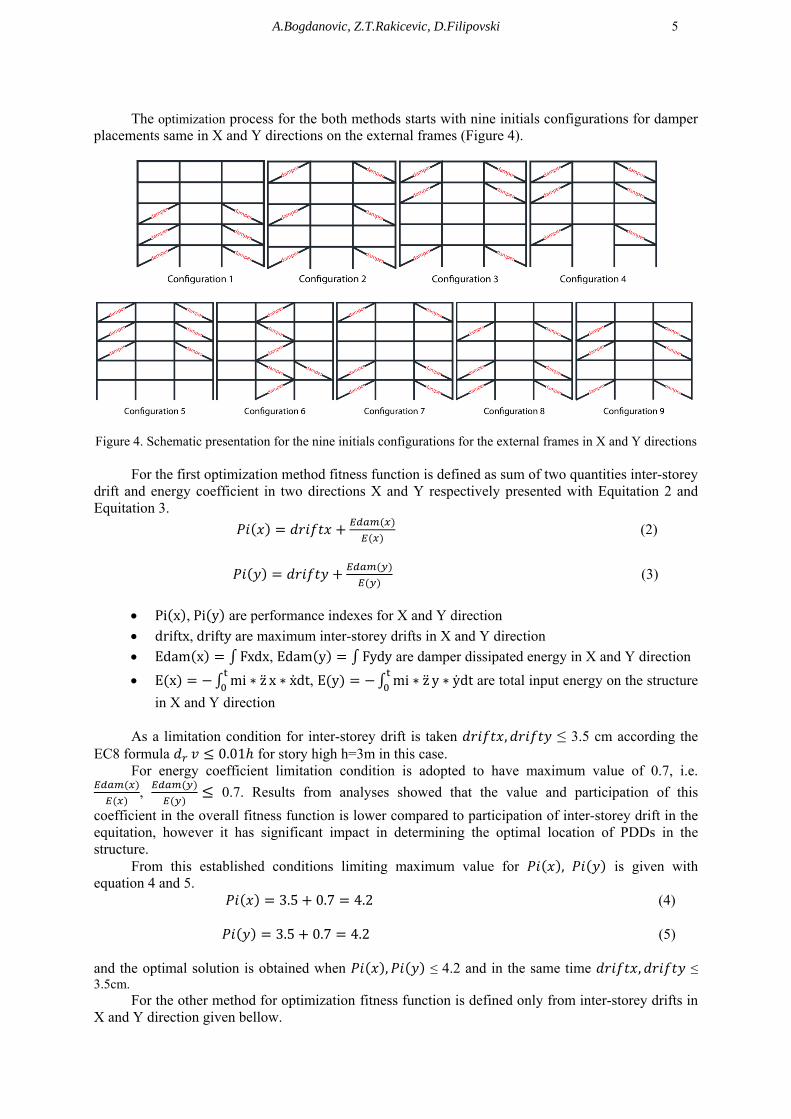
The optimization process for the both methods starts with nine initials configurations for damper
placements same in X and Y directions on the external frames (Figure 4).
Figure 4. Schematic presentation for the nine initials configurations for the external frames in X and Y directions
For the first optimization method fitness function is defined as sum of two quantities inter-storey drift and energy coefficient in two directions X and Y respectively presented with Equitation 2 and Equitation 3.
(2)
(3)
Pi x ,Pi y are performance indexes for X and Y direction
driftx,drifty are maximum inter-storey drifts in X and Y direction
Edam x Fxdx, Edam y Fydy are damper dissipated energy in X and Y direction
E x mi ∗ z x ∗ xdt, E y mi ∗ z y ∗ ydt are total input energy on the structure
in X and Y direction
As a limitation condition for inter-storey drift is taken , ≤ 3.5 cm according the EC8 formula 0.01 for story high h=3m in this case.
For energy coefficient limitation condition is adopted to have maximum value of 0.7, i.e.
, 0.7. Results from analyses showed that the value and participation of this
coefficient in the overall fitness function is lower compared to participation of inter-storey drift in the equitation, however it has significant impact in determining the optimal location of PDDs in the structure.
From this established conditions limiting maximum value for , is given with equation 4 and 5. 3.5 0.7 4.2 (4) 3.5 0.7 4.2 (5) and the optimal solution is obtained when , ≤ 4.2 and in the same time , ≤ 3.5cm.
For the other method for optimization fitness function is defined only from inter-storey drifts in X and Y direction given bellow.
6
(6) (7)
Pi x ,Pi y are performance indexes for X and Y direction
driftx,drifty are maximum interstory drifts for X and Y direction
As a limitation condition for inter-story drift is taken to be the same as for the previous case, i.e. , ≤ 3.5 cm.
In this case optimal solutions will be when , ≤ 3.5. Once the fitness of each configuration has been calculated ranking of the configuration is done according to how close each one is to the desired solution. For creating a parental pairs the value of each parental position is equal to 1/(number of configurations * 2), which in this case is 1/(2 * 9) = 0.055.
Parenting positions are filled sequentially and first are filled all the positions for the first parent and then for the second. The configuration with the largest percentage of representation in the moment always takes next free parental position and the ratio of representation reduces the value of a parental position. Then the re-ranking is done to get a new configuration with the largest coefficient. Same configuration cannot be cross-over with same and the same pair cannot appear twice in the generating of the next generation.
COMPARISONS BETWEEN TWO METHODS FOR OPTIMIZATIONS
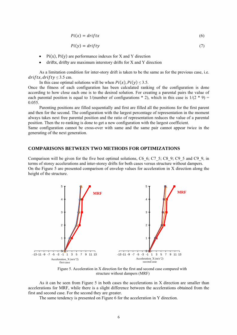
Comparison will be given for the five best optimal solutions, C6_6; C7_5; C8_9; C9_5 and C9_9, in terms of storey accelerations and inter-storey drifts for both cases versus structure without dampers. On the Figure 5 are presented comparison of envelop values for acceleration in X direction along the height of the structure.
Figure 5. Acceleration in X direction for the first and second case compared with
structure without dampers (MRF)
As it can be seen from Figure 5 in both cases the accelerations in X direction are smaller than accelerations for MRF, while there is a slight difference between the accelerations obtained from the first and second case. For the second they are greater.
The same tendency is presented on Figure 6 for the acceleration in Y direction.
0
1
2
3
4
5
-13 -11 -9 -7 -5 -3 -1 1 3 5 7 9 11 13
Acceleration_X (m/s^2)first case
0
1
2
3
4
5
-13 -11 -9 -7 -5 -3 -1 1 3 5 7 9 11 13
Acceleration_X (m/s^2)second case
MRF MRF
A.Bogdanovic, Z.T.Rakicevic, D.Filipovski 7
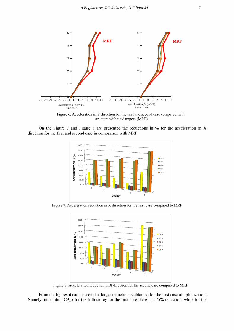
Figure 6. Acceleration in Y direction for the first and second case compared with
structure without dampers (MRF)
On the Figure 7 and Figure 8 are presented the reductions in % for the acceleration in X direction for the first and second case in comparison with MRF.
Figure 7. Acceleration reduction in X direction for the first case compared to MRF
Figure 8. Acceleration reduction in X direction for the second case compared to MRF
From the figures it can be seen that larger reduction is obtained for the first case of optimization.
Namely, in solution C9_5 for the fifth storey for the first case there is a 75% reduction, while for the
0
1
2
3
4
5
-13 -11 -9 -7 -5 -3 -1 1 3 5 7 9 11 13
Acceleration_Y (m/s^2)first case
0
1
2
3
4
5
-13 -11 -9 -7 -5 -3 -1 1 3 5 7 9 11 13
Acceleration_Y (m/s^2)second case
0.00
10.00
20.00
30.00
40.00
50.00
60.00
70.00
80.00
12
34
5STOREY
C8_9
C7_5
C6_4
C9_5
C9_9
ACCXRED
UCTION IN
(%)
0.00
5.00
10.00
15.00
20.00
25.00
30.00
35.00
40.00
12
34
5STOREY
C8_9
C7_5
C6_4
C9_5
C9_9
ACCXRED
UCTION IN
(%)
MRF MRF
8
second case the reduction is 36%. The largest reduction has been achieved for the C9_9, 77% for the first case and 36% for the second case, both for the fifth storey.
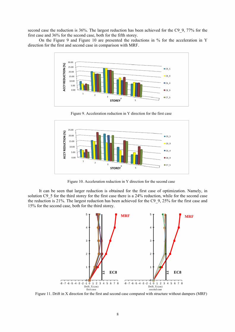
On the Figure 9 and Figure 10 are presented the reductions in % for the acceleration in Y direction for the first and second case in comparison with MRF.
Figure 9. Acceleration reduction in Y direction for the first case
Figure 10. Acceleration reduction in Y direction for the second case
It can be seen that larger reduction is obtained for the first case of optimization. Namely, in solution C9_5 for the third storey for the first case there is a 24% reduction, while for the second case the reduction is 21%. The largest reduction has been achieved for the C9_9, 25% for the first case and 15% for the second case, both for the third storey.
Figure 11. Drift in X direction for the first and second case compared with structure without dampers (MRF)
0.00
5.00
10.00
15.00
20.00
25.00
30.00
12
34
5STOREY
C9_5
C9_9
C6_4
C8_9
C7_5
ACCYRED
UCTION (%
)
0.00
5.00
10.00
15.00
20.00
25.00
12
34
5STOREY
C9_5
C9_9
C6_4
C8_9
C7_5
ACCYRED
UCTION (%
)
0
1
2
3
4
5
-8 -7 -6 -5 -4 -3 -2 -1 0 1 2 3 4 5 6 7 8Drift_X (cm)
first case
3.5
0
1
2
3
4
5
-8 -7 -6 -5 -4 -3 -2 -1 0 1 2 3 4 5 6 7 8Drift_X (cm)second case
3.5
MRF
EC8
MRF
EC8
A.Bogdanovic, Z.T.Rakicevic, D.Filipovski 9
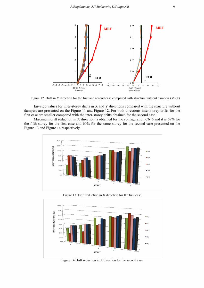
Figure 12. Drift in Y direction for the first and second case compared with structure without dampers (MRF)
Envelop values for inter-storey drifts in X and Y directions compared with the structure without
dampers are presented on the Figure 11 and Figure 12. For both directions inter-storey drifts for the first case are smaller compared with the inter-storey drifts obtained for the second case.
Maximum drift reduction in X direction is obtained for the configuration C6_6 and it is 67% for the fifth storey for the first case and 60% for the same storey for the second case presented on the Figure 13 and Figure 14 respectively.
Figure 13. Drift reduction in X direction for the first case
Figure 14.Drift reduction in X direction for the second case
0
1
2
3
4
5
-8 -7 -6 -5 -4 -3 -2 -1 0 1 2 3 4 5 6 7 8Drift_X (cm)
first case3.5
0
1
2
3
4
5
-10 -8 -6 -4 -2 0 2 4 6 8 10Drift_Y (cm)second case
3.5
0.00
10.00
20.00
30.00
40.00
50.00
60.00
70.00
1
2
3
4
5
C6_6
C7_5
C8_9
C9_5
C9_9
STOREY
DRIFTX REDUCTION (%)
0.00
10.00
20.00
30.00
40.00
50.00
60.00
70.00
80.00
1
2
3
4
5
C6_6
C7_5
C8_9
C9_5
C9_9
STOREY
DRIFTX REDUCTION (%)
EC8
MRF MRF
EC8
10
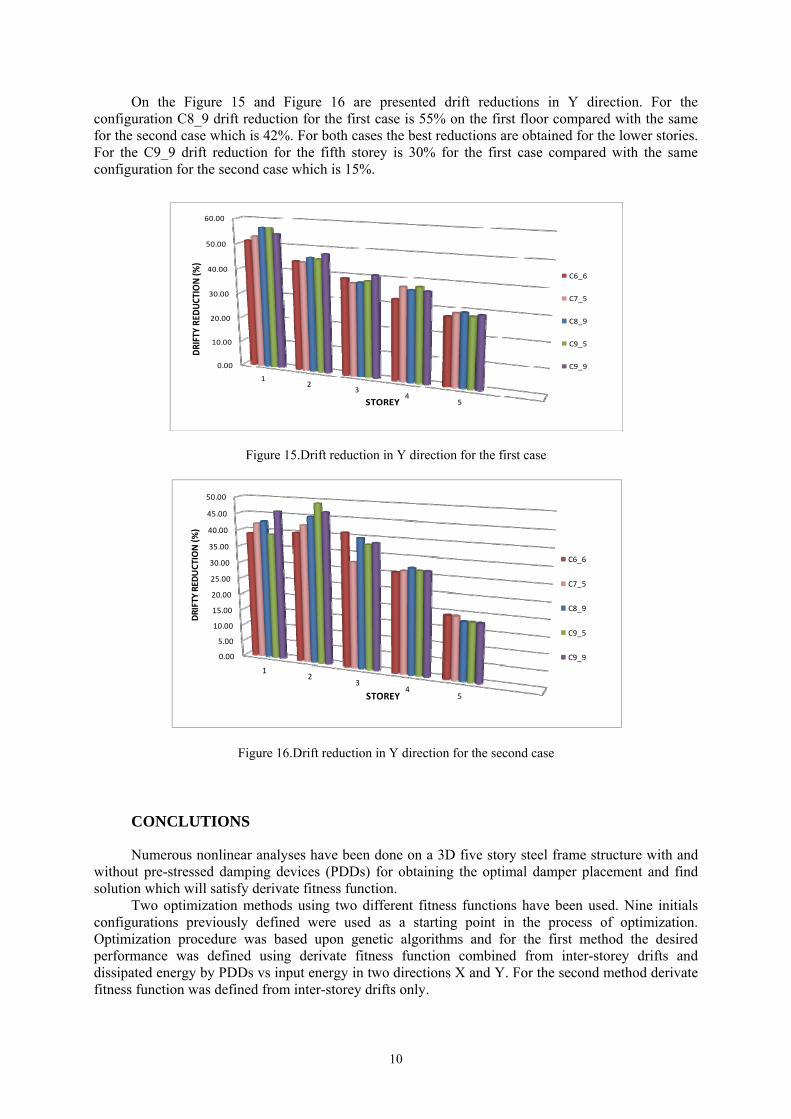
On the Figure 15 and Figure 16 are presented drift reductions in Y direction. For the configuration C8_9 drift reduction for the first case is 55% on the first floor compared with the same for the second case which is 42%. For both cases the best reductions are obtained for the lower stories. For the C9_9 drift reduction for the fifth storey is 30% for the first case compared with the same configuration for the second case which is 15%.
Figure 15.Drift reduction in Y direction for the first case
Figure 16.Drift reduction in Y direction for the second case
CONCLUTIONS
Numerous nonlinear analyses have been done on a 3D five story steel frame structure with and without pre-stressed damping devices (PDDs) for obtaining the optimal damper placement and find solution which will satisfy derivate fitness function.
Two optimization methods using two different fitness functions have been used. Nine initials configurations previously defined were used as a starting point in the process of optimization. Optimization procedure was based upon genetic algorithms and for the first method the desired performance was defined using derivate fitness function combined from inter-storey drifts and dissipated energy by PDDs vs input energy in two directions X and Y. For the second method derivate fitness function was defined from inter-storey drifts only.
0.00
10.00
20.00
30.00
40.00
50.00
60.00
12
34
5STOREY
C6_6
C7_5
C8_9
C9_5
C9_9
DRIFTY
RED
UCTION (%
)
0.00
5.00
10.00
15.00
20.00
25.00
30.00
35.00
40.00
45.00
50.00
12
34
5STOREY
C6_6
C7_5
C8_9
C9_5
C9_9
DRIFTY
RED
UCTION(%
)
A.Bogdanovic, Z.T.Rakicevic, D.Filipovski 11
Results from analyses showed that the value and participation of this coefficient in the overall fitness function is lower compared to participation of inter-storey drift in the equitation, however it has significant impact in determining the optimal location of PDDs in the structure. Visible effects were considered in the first case (case with energy coefficient) and better performance of the structure, better reduction in the response for the same configurations.
REFERENCES
Christopoulos, C., Filiatrault, A. (2006) “Principles of Passive Supplemental Damping and Seismic Isolation”, IUSS Press, Pavia, Italy.
Rakicevic, Z., Bogdanovic, A. and D. Jurukovski (2009) “Shaking Table Effectiveness Testing of GERB PDD (Prestressed Damping Device) Control System”
IZIIS Report 2009-40, Skopje, R. Macedonia. Rakicevic, Z., Bogdanovic, A., D. Jurukovski, H. Kammerer and P. Nawrotzki (2010),
“Shaking Table Testing of a Steel Frame Structure Without and With GERB Prestressed Damping Devices”, 5th World Conference on Structural Control and Monitoring, 12-14 July 2010, Tokyo, Japan, Session E-8, Paper No 226. Rakicevic, Z., Bogdanovic, A., D. Jurukovski, H. Kammerer and P. Nawrotzki (2010),
“Analytical Estimation of the Effectiveness of Prestressed Damping Devices Using Shaking Table Experiments, 14Europian Conference on Earthquake Engineering, 29-3 September, Ohrid, R.Macedonia Lago A., Sullivan, T.J., Calvi, G.M. (2012).
“Seismic Design of Structures with Passive Energy Dissipation Systems”, IUSS Report, In press. Bogdanovic, A., Rakicevic, Z., Filipovski, D., Markovski, I., (2013)
“Optimization in steel structure using genetic algorithm”, International Conference on Earthquake Engineering, 29-31 May, Skopje, R.Macedonia .