
Comparative Sudy for Grinding of Tt wo Cement ClinkersC).pdf · Comparative Sudy for Grinding of...
5
Transcript of Comparative Sudy for Grinding of Tt wo Cement ClinkersC).pdf · Comparative Sudy for Grinding of...

113
International Journal of Concrete Structures and Materials
Vol.5, No.2, pp.113~117, December 2011
http://dx.doi.org/10.4334/IJCSM.2011.5.2.113
Comparative Study for Grinding of Two Cement Clinkers
Soumaya Ibrahimi,1),* N jib Ben Jamaa,
1) Khaoula Mliki,
1) and Mohamed Bagane
2)
(Received May 30 2011, Revised August 26, 2011, Accepted August 26, 2011)
Abstract: The purpose of this work is the comparative study for grinding of two cement clinkers. X-ray fluorescence, physical
and granulometric tests and optical microscopy were used to characterize the clinkers. Also grinding tests were carried out for ten
samples to determine the parameters influencing grindability of its clinkers. The results of calculation of the energies of grinding according
to the law developed by Von Rittinger and the study of the microstructure of the two clinkers shows good agreements. Indeed, fre-
quent clusters of belite which indicate a lack of uniformity and fineness have an effect on lowering the grindability. The obtained
analyses and the results enabled us to interpret the granulometry and the microstructure of clinker to control quality and resistance.
Keywords: cement, clinker, grindability, X-ray fluorescence, optical microscopy.
1. Introduction
The aim of this work is the study for the aptitude of grinding of
two cement clinkers. These clinkers were processed in two cement
plants. To keep the rate of the cement production in the plant N°1
as constant as possible, while the kiln is in a technical arrest,
clinker from à second plan was carried out and was grinded. The
grinding of clinker represents a step of manufacture of cement
which consumes about one-third of the power required to produce
1 ton of cement. This refers to an average specific power con-
ception of 57 kWh/t.1 The following factors all affect the grinding
properties of the material to vary degrees:2
- The hardness of material expressed on Moh’s scale from 1 to 10;
- Abrasiveness: highly abrasive material requires lower mill
rotation speeds,
- Toughness or Brittleness managing the resistance to crack
propagation;
- Cohesivity (related to a lower particle size and moisture
content);
- Carrier medium;
- Milling circuit, closed with multiple passes or open and single
pass;
- Melting point of material and
- Fibrous material.
We can note that the hardness of mineral phases constituting the
clinker decrease in this order: aluminoferrite (C4AF), the belite
type II (C2S), the aluminate (C3A), the alite (C3S) and the belite
type I. Consequently, the belite type I presents the lowest Vickers
hardness. It is interressant to note also that this hardness is
influenced by the presence or not of the inclusions in the phase
and of its vicinity.3 The distribution of the phases of clinker plays a
very significant role in grinding. More the phases distributed
uniformly over the grinding of clinker will be easy. The clusters of
C2S that result from a heterogeneous raw material will also play
an important role. In this work, we treated a series of samples in
order to extract the maximum of information on the two studied
clinkers characteristics. Thus, a detailed study is made on the
chemical and mineralogical properties of clinker using the
techniques of X-ray fluorescence and optical microscopy. Grinding
tests was also carried out to determine the influence of granulometry
on the grindability of the clinker.
2. Preparation of samples
In this study we used a standard ball mill uncoated type TTS. It
is cylindrical in shape and his weight, including steel balls, is 380
kg. Samples that were the subject of this study were classified into
several size fractions: > 20 mm, 10~20 mm, 5~10 mm, < 5 mm
and the crude. For each grinding test, the ball mill is fed with a
load of: 1,425 g of clinker combined with 75 g of gypsum, and
then rotated for 10 minutes of grinding and 3 minutes of discharge
at a rate of 50 rpm. We used the law developed by von Rittinger to
compare the energies of grinding. The comparison of the behavior
of crude on the grinding for different size fractions allowed us to
make the choice of representative size fractions of each clinker.2 In
most cases, the microscopic observation of cement clinker is done
in reflected light.4 So the preparation of polished sections is
necessary. We take four to five nodules of clinker which are placed
in a cylindrical mold made of polyethylene, 40 mm in diameter
and 30 mm in height. Theses clinkers were completely immersed
in a cold mounting resin. After 20 minutes of impregnation, we
obtain a pellet clinker. The sample is cut with the saw to bring up
the nodules and get a flat section of clinker. This section was ready
for polishing on disc by using abrasive paper with adhesive
reverse of number 320, 400, 600, 800, 1,000 and 1,200µm
e′
1)Environment Catalyses and Analyzes of Processes Unit
Research, National School of Engineering of Gabes, University
of Gabes, 6029, Tunisia. *Corresponding Author; E-mail: ibrahimi.
[email protected])Applied Thermodynamics Unit Research, Gabes 6029, Tunisia.
Copyright ⓒ 2011, Korea Concrete Institute. All rights reserved,
including the making of copies without the written permission of
the copyright proprietors.
114│International Journal of Concrete Structures and Materials (Vol.5 No.2, December 2011)
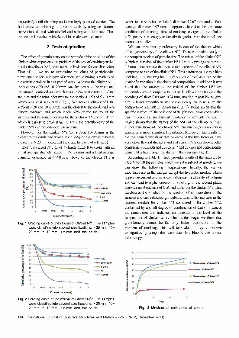
respectively until obtaining an increasingly polished section. The
final phase of polishing is done on cloth by using an alumina
suspension, diluted with alcohol and acting as a lubricant. Then
the section is washed with alcohol in an ultrasonic cleaner.5
3. Tests of grinding
The effect of granulometry on the aptitude of the crushing of the
clinker which represents the problem of the test of crushing carried
out for the clinker N°2, constitutes the basic idea for our discussion.
First of all, we try to determine the class of particle-size
representative for each type of cement while basing ourselves on
the results obtained in this part of work. Whereas the clinker N°1,
the sections > 20 and 10~20 mm was the closest to the crude and
are almost confused and which reach 67% of the totality of the
samples and the remainder was for the sections < 5 and 5~10 mm
which is the easiest to crush (Fig. 1). Whereas the clinker N°1, the
sections > 20 and 10~20 mm was the closest to the crude and was
almost confused and which reach 67% of the totality of the
samples and the remainder was for the sections < 5 and 5~10 mm
which is easiest to crush (Fig. 1). Thus, the granulometry of the
clinker N°1 can be considered as average.
However, for the clinker N°2 the section 10~20 mm is the
closest to the crude and which reach 79% of the refusal whereas
the section > 20 mm exceeded the crude to reach 84% (Fig. 2).
Thus, the clinker N°2 gives a clinker difficult to crush with an
initial average diameter equal to 19. 27 mm and a final average
diameter estimated at 4.990 mm. However the clinker N°1 is
easier to crush with an initial diameter 17.67 mm and a final
average diameter 4.97 mm. It appears clear that for the same
conditions of crushing (time of crushing, charges…) the clinker
N°2 spends more energy to transfer the grains from the initial size
to another smaller.
We can draw that granulometry is one of the factors which
affects grindability of the clinker N°2. Then, we made a study of
the samples by class of particle-size. The refusal of the clinker N°2
is higher than that of the clinker N°1 for the openings of sieve ≥
2.5 mm. That stresses the idea of the hardness of the clinker N°2
compared to that of the clinker N°1. This hardness is due to a high
cooking of the entering load (high weight of liter) as it can be the
result of a variation in the chemical composition. In addition it was
noted that the masses of the refusal of the clinker N°2 are
remarkably lower compared to that of the clinker N°1 between the
openings of sieve 0.09 and 0.04 mm, making it possible to give
him a better smoothness and consequently an increase in the
compressive strength in long-term (Fig. 3). Being given that the
specific surface of Blaine is one of the physical parameters which
can influence the mechanical resistance of cement, the test of
Blaine shows that the values of the SSB of the clinker N°2 are
higher than those of the clinker N°1. So this higher smoothness
generates a more significant resistance. Moreover, the results of
the mechanical test show that cements of the two factories have
very close flexural strengths and that cement N°2 develops a better
compressive strength and this for 2, 7 and 28 days and consequently
cement N°2 has a larger resistance in the long run (Fig. 3).
According to Table 1, which provides results of the analyses by
Fluo X for all the samples which were the subject of grinding, we
can draw the following interpretations: Initially, the various
modulates are in the margin except the hydraulic module which
appears exceeded and so it can influence the stability of volume
and can lead to a phenomenon of swelling. In the second place,
there are an abundance of C3A and C4AF for the clinker N°2 what
accelerates the kinetics of the reaction of clinkerisation in the
furnace and can influence grindability. Lastly, the increase in the
alumina module for clinker N°1 compared to the clinker N°2,
confirmed by a small degree of combination of CaO, influences
the granulation and indicates an increase to the level of the
temperature of clinkerisation. Thus at this stage, we think that
granulometry cannot be the only factor responsible for the
problem of crushing. This will take along to try to remove
ambiguities by using other techniques like Fluo X and optical
microscopy.
Fig. 1 Grading curve of the refusal of Clinker No
1. The samples
were classified into several size fractions: > 20 mm, 10~
20 mm, 5~10 mm, < 5 mm and the crude.
Fig. 2 Grading curve of the refusal of Clinker No
2. The samples
were classified into several size fractions: > 20 mm, 10~
20 mm, 5~10 mm, < 5 mm and the crude. Fig. 3 Mechanical resistance of cement.

International Journal of Concrete Structures and Materials (Vol.5 No.2, December 2011)│115
4. Characterization under the optical microscope
By taking account of the resemblance of the various phases of
the clinker, a surface chemical attack must be made on all the
samples in order to make appear the various phases of the clinker.
The crystals of alite (C3S) are prismatic, those of belite (C2S) are
rounded and the interstitial mass (C3A + C4AF) is clear. In our
study, we choose the eight samples of crushing and also ten
samples among the twenties, already taken to treat, to be attacked
with hydrofluoric acid (Fig. 4a and 4b) and nitric acid HNO3 with
0.25 % in alcohol (Fig. 5a and 5b).
4.1 Attack by the vaporized hydrofluoric acidAfter its polishing, the section is exposed to the vapor of
hydrofluoric acid during 10 to 20 s then ventilated by a water
vapor using hair dryer to avoid the deterioration of the objectives
of the microscope.4 The crystals of alite (C3S) are prismatic,
sometimes tabular, cover the majority of surface observed and
their size varying between 13 and 70 µm. They contain sometimes
inclusions of belite (C2S). The crystals rounded of belite are
striated and frequently grouped in cluster and their size varies
from 10 to 40µm. The most widespread phase in the industrial
clinkers is the phase β. They show sometimes a digitation due to a
reaction of fusion and testifying to a slow cooling of the clinker.6
Aluminate (C3A) appears gray in a clearer matrix consisted of
alumino-ferrite (C4AF).
4.2 Interpretations of microstructureThe observation of the fine texture of the clinker obtained via
optical microscopy makes it possible to follow the parameters
managing the manufacturing process in the furnace what makes it
possible to improve quality of cement. The determination of the
potential phases of the clinker on a microscopic image becomes
easier with the chemical attacks carried out on the samples to
analyze. The alite (C3S) has a prismatic texture and allows
controlling the parameters of heating in the furnace. The bélite
appears round and dependent with alite by the interstitial mass; it
informs on the stage of cooling. By taking account of the
difference of the areas of the two types of clinker N°1 and N°2
Table 1. Chemical composition of the different clinkers (wt %) determined by XRF. The clinkers come from two different cement
plants N°1 and N°2.
Clinker N°1 Clinker N°2
SampleN° 1 2 3 4 1 2 3 4
CaO 65.96 67.19 67.47 66.57 65.76 65.87 67.53 67.49
SiO2 22.24 22.06 22.25 21.72 21.33 21.47 21.99 21.8
Al2O3 4.79 4.36 4.57 4.99 6.11 5.91 4.62 4.68
Fe2O3 3.24 3.02 3.16 3.09 3.38 3.25 3.16 3.25
SO3 1.24 0.76 0.37 1.13 0.70 0.71 0.30 0.31
K2O 0.55 0.42 0.31 0.57 0.61 0.60 0.30 0.30
Cl 0.0143 0.0140 0.0151 0.0131 0.0149 0.0169 0.0120 0.0117
MgO 1.39 1.32 1.34 1.35 1.10 1.11 1.34 1.34
TiO2 0.25 0.23 0.24 0.25 0.26 0.25 0.24 0.24
Na2O 0.11 0.10 0.09 0.11 0.10 0.10 0.10 0.10
Total 99.78 99.47 99.82 99.79 99.36 99.29 99.59 99.52
Free lime 2.17 0.70 0.88 1.43 1.07 1.07 0.46 0.48
HRS 24.29 22.08 23.15 25.40 31.23 30.22 23.41 23.70
CiS 76.50 80.07 80.18 77.14 74.67 75.28 80.36 79.97
C/S 2.97 3.05 3.03 3.06 3.08 3.07 3.07 3.10
C3S DRX 46.70 70.70 68.20 58.80 52.60 56.00 72.40 73.30
C2S DRX 26.60 15.90 16.00 21.10 21.80 21.40 14.30 14.00
C3S 51.50 68.13 66.34 60.18 54.68 55.55 70.11 70.75
C2S 25.00 11.94 13.83 16.96 19.99 19.74 10.24 9.22
C3A 7.22 6.45 6.77 8.00 10.48 10.17 6.90 6.91
C4AF 9.85 9.18 9.61 9.39 10.28 9.88 9.61 9.88
AM 1.48 1.44 1.45 1.61 1.81 1.82 1.46 1.44
SM 2.77 2.99 2.88 2.69 2.25 2.34 2.83 2.75
LSF 94.19 97.55 96.74 96.88 95.12 95.18 97.76 98.27
HM 3.19 3.24 3.24 3.36 3.54 3.50 3.29 3.31
HRS: Relation between tricalcium aluminate and aluminate tetracalcic, XRD: X - Ray Diffraction, AM: Aluminoferrique Modulate, SM: Silicic
Module, LSF: Lime Saturation Factor and HM: Hydraulic Modulate.

116│International Journal of Concrete Structures and Materials (Vol.5 No.2, December 2011)
and of the problem encountered with the grinding of the clinker
N°2, we waited until the chemical composition of the components
as well as the fine texture of the two types of clinker are different.
That requires an in-depth study for each type of clinker.
The observation of the microscopic images of the clinker N°1
enables us to gather following information: The distribution of the
various phases of the clinker is almost homogeneous (Fig. 5a), the
alite is prismatic, the belite is round and the interstitial mass is well
differentiated. So the conditions of manufacture in the furnace are
acceptable, the chemical composition of the vintage is correct,
well mixed vintage, the particles are not coarse, as well as the
temperatures of heating and of cooling are satisfactory. But that
does not exclude the existence of the clusters of belite near large
crystals of alite resulting from a slow heating. These phenomena
are frequent and due to the weak variations of the parameters of
production which are difficult to maintain always fixed during the
walk of the furnace. We observe also transformations of phase
C3S into C2S. Digitations are formed on the belite (Fig. 5b) and
also inclusions of belite in alite are observed. This transformation
could reduce the resistance in short-term of cement and influence
the time of cooling of the clinker. These phenomena remain weak
compared to those observed in the clinker N°2. If we refer to the
analysis by Fluo X, we note that the concentration of SO3 was
high, for the launching period of the furnace before the
establishment of the regular mode, which can be at the origin of
broad pores, belite dispersed and large crystals of alite are
observed in the majority of the samples of the clinker N°1.8-9
The
identification of the phases on a microscopic image enables us to
make a synthesis of the fine texture of the clinker N°2, so that we
can detect the anomalies met in the manufacturing process of
cement (for example: cooking, crushing…). In the majority of the
samples, the distribution of the various phases is heterogeneous; the
crystals of alite appear tubular and damaged. They show in certain
cases a zonation. The crystals of alite present an unstable mode of
growth whose morphology is irregular and containing a great
quantity of round inclusions of belite (Fig. 6a). Transformations of
alite in belite are rather remarkable witnessing a transformation
during a slow cooling. The crystals of belite have a variable forms
sometimes round and of another time notched. They are frequently
striated and show a digitation (Fig. 6b) due to maintenance to a
long time at high temperature, also justified by a high weight of
the liter for all the samples, and testifying to a slow cooling of the
clinker.6 Crystals of C2S are located on the edges of those of C3S
and appear increasing with their detriment. This phenomenon is
due primarily at a relatively slow speed of cooling. However the
notable reduction in C3S can generate a low compressive strength
of cement. The clusters of belite and of alite rather remarkable
result, generally, either of a bad homogenization of the raw
material or of a bad crushing of the raw mixture, especially when
dimensions of the particles are excessively large in the raw
mixture (diameter of grain larger than 0.1 mm)4 (Fig. 4b). Indeed,
the large crystals of silica (SiO2) or of lime (CaO) are at the base
of this phenomenon. In the samples of the clinker N°2 the phases
are small, badly formed, porosity is average, the distribution of the
phases is irregular, alite is surrounded by great quantities of liquid
phase where the C3A appears gray in a clearer matrix composed
of C4AF (Fig. 6a) and the belite exists in clusters what makes
difficult the crushing of the clinker.
5. Conclusions
This study was carried out in the framework of a research
project having for goal the comparison between two clinkers
which classified into several grades. This work rests on a
bibliographical study which is used for the analysis of the results,
followed by an experimental study primarily made up of two
Fig. 4 (a) Micrography of the clinker No
2, Polished section
attacked by the vaporized hydrofluoric acid (40%). The
crystals of belite are rounded and blue. The crystals of
alite are prismatic and brown. The interstitial mass is
well crystallized and white. The pores are black,
(x100). (b) Micrography of the clinker No
2. Polished
section attacked by the vaporized hydrofluoric acid
(40%). Heterogeneous distribution of the phases. Cluster
of belite, (x200).
Fig. 5 (a) Micrography of the clinker No
1. Homogeneous
distribution of the phases, (x100). Polished section
attacked with a nitric acid solution in alcohol. The
prismatic alite is light blue, the round belite is blue dark
and the interstitial mass is white, (x100). (b) Micrography
of the clinker No
1. Polished section attacked with a
nitric acid solution in alcohol. Digitations of C2S, (x400).
Fig. 6 (a) Micrography of the clinker No
2. Polished section
attacked by the vaporized hydrofluoric acid (40%).
Abundance of inclusions of belite in the crystals of alite,
(x400). (b) Micrography of the clinker No
2. Polished
section attacked by the vaporized hydrofluoric acid (40%),
The rounded crystals of belite appear striated (blue). The
crystals of alite are brown. The interstitial mass is well
differentiated, (x200).

International Journal of Concrete Structures and Materials (Vol.5 No.2, December 2011)│117
parts. Initially, a test of crushing is carried out by stressing the
effect of the difference of granulometry on the difficulty of
grndinging. In the second place we had recourse to optical
microscopy in the identification of the various potential phases of
the clinker (alite, belite, aluminate and ferrite) and to make a
dimensional analysis of these phases. Thus, we established a
relation between these characteristics, on one hand, the quality and
the resistance of the two types of cement as well as the anomalies
met in the crushing and in the manufacturing process on the other
hand. At this level, we can conclude that the variations between
the two clinkers especially on the level of crushing are due to
several characteristics such as: granulometry, the chemical com-
position, the minor elements (alkali, free lime), burning conditions
thus it is a whole matrix which is responsible for the differences
met at the time of the study of these two types of clinker. So it is
necessary to have for the spirit that a well done nodule of the
clinker must have a uniform distribution of the crystals of alite
generally small, a microporosity well developed in the matrix and
especially to have a mix vintage well homogenized and relatively
stable conditions of manufacture. Finally, if we analyze the recent
past, we note that the techniques used to follow morphology, to
measure the sizes as well as to quantify the mineralogical phases
of the clinker, underwent successive improvements to give the
most relevant information. Among the most advanced techniques,
we can improve this work by the use of diffraction of x-rays. This
technique allows the identification of the crystalline phases and
their quantification while being based on the Rietveld method.
Acknowledgements
The authors wish to thank the Cement Company of Gabes for
the material support. The work was supported financially by the
Tunisian Libyan Project on cement quality.
References
1. Seebach MV., Schneider L., Update on finish grinding with
improved energy efficiency. World Cem., Vol. 17, No. 8, 1986, pp.
336~46.
2. Rhodes M., Introduction to Particels Technology, John Wiley
& Sons, Brisbane, 1998.
3. De Souza V.C.G., Koppe J. C., Costa J.F.C.L., Vargas A.L.M.,
Blando E., Hübler R., The influence of mineralogical, chemical
and physical properties on grindability of commercial clinkers
with high MgO level. Cement and Concrete Research, 38, 2008,
pp. 1119~1125.
4. Donald H. Campbell, Microscopical Examination and
Interpretation of Portland Cement and Clinker, Portland Cement
Association, Second Edition, SP030, 30~128, 1999.
5. Ben Jamaa N. and Maki I, Characterization of Tunisian Port-
land cement clinkers by optical microscopy, SEM and micro-
probe analysis, Ann. Chim. Sci. Mat., Vol. 31, No. 4, 2006, pp.
421~430.
6. Maki I. Processing conditions of Portland cement clinker
as viewed from the fine textures of the constituent minerals. Am.
Ceram. Soc., 40, Ceramic transactions, 1994, pp. 3~17.
7. Maki I., Some characteristic microscopic textures of the
Portland cement constituent minerals and the processing condi-
tions in the kiln, Proc. 23rd Int. Conf. Cement Microscopy 2001.
8. Hofmänner F., Microstructure of Portland Cement Clinker,
Holderbank Management and Consulting, Ltd., Holderbank, Swit-
zerland, 1973.
9. Tsuboi T., and Ogawa T., Microscopic Studies of Clinker
for Evaluating the Sintering Process, Zement-Kalk-Gips, Vol.
25, No. 6, 1972, pp. 292~294.