
Comparative analysis of HVDC and EHVAC · Comparative analysis of HVDC and EHVAC Pallavi Gamit1,...
7
International Research Journal of Engineering and Technology (IRJET) e-ISSN: 2395 -0056 Volume: 02 Issue: 09 | Dec-2015 www.irjet.net p-ISSN: 2395-0072 © 2015, IRJET ISO 9001:2008 Certified Journal Page 1165 Comparative analysis of HVDC and EHVAC Pallavi Gamit 1 , Nidhi Shah 2 , Umang Wani 3 , Priyanka Patel 4 , Unnati Mali 5 , Ashish Chaudhari 6 1, 2, 3,4,5,6 Assistant Professor, Electrical Engineering Department, C. G. Patel Institute of Technology, Bardoli, Gujarat, India ---------------------------------------------------------------------***--------------------------------------------------------------------- Abstract - High voltage direct current (HVDC) technology has characteristics which make it especially attractive in certain transmission applications. The number of HVDC projects accomplished or under consideration globally has increased in recent years reflecting a renewed interest in this field proven technology. New HVDC converter designs and improvements in conventional HVDC design have contributed to this trend. AC is the main driving force in industries and residential areas but for long transmission line AC transmission is more expensive than DC. AC transmission have more complications because of frequency where in DC transmission frequency is absent. This paper provides an overview of HVDC and HVAC transmission system. This provides the basic literature survey for researchers. It also gives comparison between HVDC and EHVAC transmission lines. Key Words: HVDC, HVAC transmission 1 Historical Background Power Transmission was initially carried out in the early 1880s using Direct Current (d.c.). With the availability of transformers (for stepping up the voltage for transmission over long distances and for stepping down the voltage for safe use), the development of robust induction motor (to serve the users of rotary power), the availability of the superior synchronous generator, and the facilities of converting a.c. to d.c. when required, a.c. gradually replaced d.c. 1.1 Important milestone in the development of HVDC Technology. Hewitt’s mercury – vapour rectifier, which appeared in 1901. Experiments with thyratons in America and mercury arc valves in Europe before 1940. First commercial HVDC transmission, Gotland 1 in Sweden 1954. First solid state semiconductor valves in 1970. First microcomputer based control equipment for HVDC in 1979. Highest DC transmission voltage (+/- 600 kV) in Itaipu, Brazil, 1984. First active DC filters for outstanding filtering performance in 1994. First Capacitor commutated Converter (CCC) in Argentina- Brazil interconnection, 1998. First voltage source converter for transmission in Gotland, Sweden, 1999.[2] 1.2 Projects carried out in HVDC. There are many different reasons as to why HVDC was chosen. A few of the reasons selected projects are: In Itaipu, Brazil, HVDC was choosen to supply 50 Hz power into a 60 Hz system and to economically transmit large amount of hydro power over large distances. In leyte- Luzon project in Philippines, HVDC was Chosen to enable supply of bulkgeo thermal power across an island interconnection. And to improves stability to the manila AC network. In Rihand – Delhi project in India, HVDC was chosen to transmit bulk (thermal) power (1500MW) to Delhi, to ensure minimum losses, least amount right- of- way, and better stability and control. In Garabi, an independent transmission project (ITP) transferring power from Argentina to brazil, HVDC back- to-back system was chosen to ensure supply of 50 HZ bulk(1000MW) power to a 60 Hz system under a 20- year power supply contract.
Transcript of Comparative analysis of HVDC and EHVAC · Comparative analysis of HVDC and EHVAC Pallavi Gamit1,...
International Research Journal of Engineering and Technology (IRJET) e-ISSN: 2395 -0056
Volume: 02 Issue: 09 | Dec-2015 www.irjet.net p-ISSN: 2395-0072
© 2015, IRJET ISO 9001:2008 Certified Journal Page 1165
Comparative analysis of HVDC and EHVAC
Pallavi Gamit1, Nidhi Shah2, Umang Wani 3, Priyanka Patel4, Unnati Mali5, Ashish Chaudhari6
1, 2, 3,4,5,6 Assistant Professor, Electrical Engineering Department, C. G. Patel Institute of Technology, Bardoli, Gujarat, India
---------------------------------------------------------------------***---------------------------------------------------------------------Abstract - High voltage direct current (HVDC)
technology has characteristics which make it especially
attractive in certain transmission applications. The
number of HVDC projects accomplished or under
consideration globally has increased in recent years
reflecting a renewed interest in this field proven
technology. New HVDC converter designs and
improvements in conventional HVDC design have
contributed to this trend. AC is the main driving force in
industries and residential areas but for long
transmission line AC transmission is more expensive
than DC. AC transmission have more complications
because of frequency where in DC transmission
frequency is absent. This paper provides an overview of
HVDC and HVAC transmission system. This provides the
basic literature survey for researchers. It also gives
comparison between HVDC and EHVAC transmission
lines.
Key Words: HVDC, HVAC transmission
1 Historical Background Power Transmission was initially carried out in the early 1880s using Direct Current (d.c.). With the availability of transformers (for stepping up the voltage for transmission over long distances and for stepping down the voltage for safe use), the development of robust induction motor (to serve the users of rotary power), the availability of the superior synchronous generator, and the facilities of converting a.c. to d.c. when required, a.c. gradually replaced d.c.
1.1 Important milestone in the development of
HVDC Technology.
Hewitt’s mercury – vapour rectifier, which
appeared in 1901.
Experiments with thyratons in America and
mercury arc valves in Europe before 1940.
First commercial HVDC transmission, Gotland 1 in
Sweden 1954.
First solid state semiconductor valves in 1970.
First microcomputer based control equipment for
HVDC in 1979.
Highest DC transmission voltage (+/- 600 kV) in
Itaipu, Brazil, 1984.
First active DC filters for outstanding filtering
performance in 1994.
First Capacitor commutated Converter (CCC) in
Argentina- Brazil interconnection, 1998.
First voltage source converter for transmission in
Gotland, Sweden, 1999.[2]
1.2 Projects carried out in HVDC.
There are many different reasons as to why HVDC was
chosen. A few of the reasons selected projects are:
In Itaipu, Brazil, HVDC was choosen to supply 50 Hz power
into a 60 Hz system and to economically transmit large
amount of hydro power over large distances.
In leyte- Luzon project in Philippines, HVDC was Chosen to
enable supply of bulkgeo thermal power across an island
interconnection. And to improves stability to the manila
AC network.
In Rihand – Delhi project in India, HVDC was chosen to
transmit bulk (thermal) power (1500MW) to Delhi, to
ensure minimum losses, least amount right- of- way, and
better stability and control.
In Garabi, an independent transmission project (ITP)
transferring power from Argentina to brazil, HVDC back-
to-back system was chosen to ensure supply of 50 HZ
bulk(1000MW) power to a 60 Hz system under a 20- year
power supply contract.
International Research Journal of Engineering and Technology (IRJET) e-ISSN: 2395 -0056
Volume: 02 Issue: 09 | Dec-2015 www.irjet.net p-ISSN: 2395-0072
© 2015, IRJET ISO 9001:2008 Certified Journal Page 1166
In Gotland, Sweden, HVDC was chosen to connect a newly
developed wind power site to the environmental
sensitivity of the project area and improve power quality.
In Queensland, Australia, HVDC was chosen in an ITP to
interconnect two independent grids to: enable electricity
trading between the two systems, ensure very low
environmental impact and reduce construction time.[2]
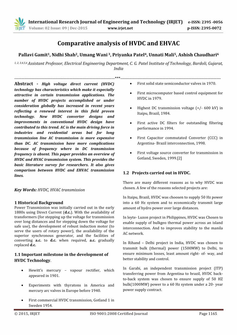
2 Types of HVDC Systems There are mainly three types of HVDC Links that are use. 2.1 Monopolar Link A monopolar system has only one conductor with ground as return conductor, and it is usually of a negative polarity. It is suitable in submarine systems where sea water can be used as a return conductor.
Fig -1: Monopolar link
2.2 Bipolar Link A Bipolar system has two conductors, one of positive and other of negative polarity. The mutual or ground point is maintained at the mid-potential. Each terminal of a bipolar system has two converters of equal voltage rating connected in series. If both neutrals are grounded then two poles operate at equal current and there is no ground current. In the event of fault in one conductor, the other conductor with ground return can be used up to half the rated load or power with the rated current of the pole.
Fig -2: Bipolar link
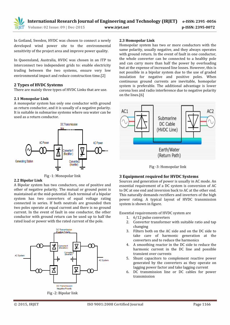
2.3 Homopolar Link Homopolar system has two or more conductors with the same polarity, usually negative, and they always operates with ground return. In the event of fault in one conductor, the whole converter can be connected to a healthy pole and can carry more than half the power by overloading but at the expense of increased line losses. However, this is not possible in a bipolar system due to the use of graded insulation for negative and positive poles. When continuous ground currents are inevitable, homopolar system is preferable. The additional advantage is lower corona loss and radio interference due to negative polarity on the lines.[6]
Fig -3: Homopolar link
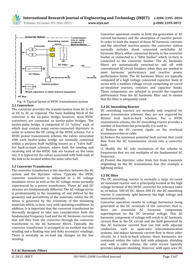
3 Equipment required for HVDC Systems Sources and generation of power is usually in AC mode. An essential requirement of a DC system is conversion of AC to DC at one end and inversion back to AC at the other end. This naturally demands rectifiers and inverters of the high power rating. A typical layout of HVDC transmission system is shown in figure. Essential requirements of HVDC system are
1. 6/12 pulse converters 2. Converter transformer with suitable ratio and tap
changing 3. Filters both on the AC side and on the DC side to
take care of harmonic generation at the converters and to reduce the harmonics
4. A smoothing reactor in the DC side to reduce the harmonic current in the DC line and possible transient over currents
5. Shunt capacitors to complement reactive power generated by the converters as they operate on lagging power factor and take lagging current
6. DC transmission line or DC cables for power transmission
International Research Journal of Engineering and Technology (IRJET) e-ISSN: 2395 -0056
Volume: 02 Issue: 09 | Dec-2015 www.irjet.net p-ISSN: 2395-0072
© 2015, IRJET ISO 9001:2008 Certified Journal Page 1167
Fig -4: Typical layout of HVDC transmission system
3.1 Converters The converter provides the transformation from AC to DC or DC to AC as required. The basic building block of the converter is the six-pulse bridge; however, most HVDC converters are connected as twelve-pulse bridges. The twelve-pulse bridge is composed of 12 “valves” each of which may contain many series-connected thyristors in order to achieve the DC rating of the HVDC scheme. For a HVDC power transmission scheme, the valves associated with each twelve-pulse bridge are normally contained within a purpose built building known as a “valve hall”. For back-to-back schemes, where both the sending and receiving end of the HVDC link are located on the same site, it is typical for the valves associated with both ends of the link to be located within the same valve hall. 3.2 Converter Transformer The converter transformer is the interface between the AC system and the thyristor valves. Typically the HVDC converter transformer is subjected to a DC voltage insulation stress as well as the AC voltage stress normally experienced by a power transformer. These AC and DC stresses are fundamentally different. The AC voltage stress is predominantly in the insulating oil and defined by the geometry and permittivity of the materials, whilst the DC stress is governed by the resistivity of the insulating materials which, in turn, vary with operating conditions. In addition, it is important that the converter transformer be thermally designed to take into consideration both the fundamental frequency load and the AC harmonic currents that will flow from the converter through the converter transformer to the AC harmonic filters. Typically, the converter transformer is arranged as an earthed star-line winding and a floating-star and delta secondary windings. There is normally an on-load tap changer on the line winding. 3.3 AC Harmonic Filters
Converter operation results in both the generation of AC current harmonics and the absorption of reactive power. In order to limit the impact of these AC harmonic currents and the absorbed reactive power, the converter station normally includes shunt connected switchable AC harmonic filters, either connected directly to the converter busbar or connected to a “filter busbar” which, in-turn, is connected to the converter busbar. The AC harmonic filters are automatically switched-on and off with conventional AC circuit breakers when they are needed to meet harmonic performance and reactive power performance limits. The AC harmonic filters are typically composed of a high voltage connected capacitor bank in series with a medium voltage circuit comprising air-cored air-insulated reactors, resistors and capacitor banks. These components are selected to provide the required performance from the AC harmonic filter and to ensure that the filter is adequately rated. 3.4 DC Smoothing Reactor DC smoothing reactors are normally only required for power transmission schemes; they are not required for Alstom Grid back-to-back schemes. For a HVDC transmission scheme, the DC smoothing reactor provides a number of functions but principally it is used to: a) Reduce the DC current ripple on the overhead transmission line or cable. b) Reduce the maximum potential fault current that could flow from the DC transmission circuit into a converter fault. c) Modify the DC side resonances of the scheme to frequencies that are not multiples of the fundamental AC frequency. d) Protect the thyristor valve from fast front transients originating on the DC transmission line (for example a lightning strike). 3.5 DC filter The DC smoothing reactor is normally a large air-cored air-insulated reactor and is principally located at the high voltage terminal of the HVDC converter for schemes rated at, or below, 500 kV DC. Above 500 kV, the DC smoothing reactor is commonly split between the high voltage and neutral terminals. Converter operation results in voltage harmonics being generated at the DC terminals of the converter, that is, there are sinusoidal AC harmonic components superimposed on the DC terminal voltage. This AC harmonic component of voltage will result in AC harmonic current flow in the DC circuit and the field generated by this AC harmonic current flow can link with adjacent conductors, such as open-wire telecommunication systems, and induce harmonic current flow in these other circuits. In a back-to-back scheme, these harmonics are contained within the valve hall with adequate shielding and, with a cable scheme, the cable screen typically provides adequate shielding. However, with open-wire DC

International Research Journal of Engineering and Technology (IRJET) e-ISSN: 2395 -0056
Volume: 02 Issue: 09 | Dec-2015 www.irjet.net p-ISSN: 2395-0072
© 2015, IRJET ISO 9001:2008 Certified Journal Page 1168
limit the amount of harmonic current flowing in the DC line. The DC filter is physically similar to an AC filter in that it is connected to the high voltage potential via a capacitor bank; other capacitors along with reactors and resistors are then connected to the high voltage capacitor bank in order to provide the desired tuning and damping.
3.6 Transmission line For bulk power transmission over land, the most frequent
transmission medium used is the overhead line. This
overhead line is normally bipolar, i.e. two conductors with
different polarity. HVDC cables are normally used for
submarine transmission. The most common types of
cables are the solid and the oil-filled ones. The solid type is
in many cases the most economic one. Its insulation
consists of paper tapes impregnated with high viscosity
oil. No length limitation exists for this type and designs are
today available for depths of about 1000 m. The self –
contained oil-filled cable is completely filled with low
viscosity oil and always works under pressure. The
maximum length for this cable type seems to be around 60
km.
The development of new power cable technologies has
accelerated in recent years and today a new HVDC cable is
available for HVDC underground or submarine power
transmissions. This new HVDC cable is made of extruded
polyethylene, and is used in VSC based HVDC systems.[5]
3.7 Advantage of HVDC Transmission Required less space Ground can be used as return conductor Less corona loss and No reactive power loss Cheaper for long distance transmission No skin and Ferranti effect Asynchronous operation possible No switching transient No transmission of short circuit power control
possible No stability problem[11]
3.8 Disadvantage of HVDC Transmission Cost of terminal equipment high Introduction of harmonics Blocking of reactive power[11]
3.9 Following are the transmission line rates in India
Sr. From To Power Voltage
1 Rihland
(U.P)(from
1990)
Dadri
(pehli)
15000
MW
±500 KV
(bipolar)
2 Talcher-is the
biggest HVDC
transmission
passes through
Orissa(A.P)
Tamilnadu &
Karnataka
Kolar 2000
MW
± 500 KV
(bipolar)
3 Chandrapur-
padghe
(Maharastra)
Padghe
(Mahara
stra)
1500
MW
± 500 KV
(bipolar)
4 Western
Region
Norther
n Region
500MW -
5 Western
Region
Norther
n Region
100MW -
4. HVAC Transmission System (Electric Power Transmission Lines)
4.1 Introduction to HVAC Transmission System
The increased demand of electricity needs more generation of electrical power. As the generation takes place at remote places, an efficient distribution system is necessary. The problems of AC transmission particularly in long distance transmission have led to the development of DC transmission.
HVAC Transmission system can be divided into two parts:
(a) Transmission System
(b) Distribution System
Each part is again subdivided into two parts:
1. Primary Transmission
2. Secondary Transmission
Generation and transmission now days is almost three phase. The secondary transmission is also three phase whereas the distribution to the customer may be three phase or single depending on the requirement of the consumer. [10]

International Research Journal of Engineering and Technology (IRJET) e-ISSN: 2395 -0056
Volume: 02 Issue: 09 | Dec-2015 www.irjet.net p-ISSN: 2395-0072
© 2015, IRJET ISO 9001:2008 Certified Journal Page 1169
Fig -5: HVAC Transmission System
4.2 Primary Transmission
In fig the central station CS generates power using three phase alternators at 6.6 or 11 or 13.2 or 32 kV. The voltage is then stepped up by suitable three phase transformers, to 132 kV as shown.
Such a high voltage of transmission requires conductors of smaller cross section which results reduction in the cost of copper or aluminium.
However the cost of insulation increases. The transmission voltage is therefore determined by economic considerations. Higher transmission voltage also reduces the line losses and improves the efficiency.
The three phase three wire overhead high voltage transmission line gets terminated in the step down transformers in a substation known as Receiving Station (RS).
Receiving station is usually situated outside the city to ensure safety. Here the voltage is stepped down to 33 kV from 132 kV.[10]
4.3 Secondary Transmission
From The receiving station, power is then transmitted at 33kv by underground cables located at various points in the city. This is known as secondary or low voltage transmission. At substation this is further reduced from 3kV to 3.3 kV, using step down transformers.
4.4 Primary Distribution
The output of substation at 3.3 kV can be directly given to a customer whose demand exceeds 50kVA using special feeders. This is primary distribution.
4.5 Secondary Distribution
The secondary distribution is done at 440 or 230 V. The reduction in voltage level from 3.3 kV to 440/230 V is done by the step down transformers at the distribution substations.
The most common system for secondary distribution is 440/230 V, three phase, four wire system. The single phase residential load is connected between any one line and the neutral where as three phases 440 V, motor load is connected across the phase lines directly. The standard frequency for a.c. working is 50 Hz in India and 60 Hz for U.S.A. For single phase traction applications, frequencies as low as 25 or 16.67 Hz are also used.
Classification of transmission line A transmission line has three constants R, L, C distributed uniformly along the whole length of the line. The resistance and inductance form the series impedance. The capacitance existing between conductors for 1-phase line or from a conductor to neutral for a 3-phase line forms a shunt path throughout the length of the line. Therefore, capacitance effect introduces complications in transmission line calculations. Depending upon the manner in which capacitance is taken into account: the overhead transmission lines are classified as: (i) Short Transmission Line: when the length of an overhead transmission line is up to about 50 Km and the line voltage is comparatively low (<20 KV), it is usually considered as a short transmission line. Due to smaller length and lower voltage, the capacitance effects are small and hence can be neglected. Therefore, while studying the performance of a short transmission line, only resistance and inductance of the line are taken into account. (ii) Medium Transmission Line: when the length of an overhead transmission line is about 50-150 Km and the line voltage is moderately high (>20 KV <100), it is considered as a medium transmission line. Due to sufficient length and voltage of the line, the capacitance effects are taken into account. For purpose of calculations, the distributed capacitance of the line is divided and lumped in the form of condensers shunted across the line at one or more points. (iii) Long Transmission Line: when the length of an overhead transmission line is more than 150 Km and line voltage is very high (.100 KV), it is considered as a long transmission line. For the treatment of such a line, the line constants are considered uniformly distributed over the whole length of the line and rigorous methods are employed for solution.[10]

International Research Journal of Engineering and Technology (IRJET) e-ISSN: 2395 -0056
Volume: 02 Issue: 09 | Dec-2015 www.irjet.net p-ISSN: 2395-0072
© 2015, IRJET ISO 9001:2008 Certified Journal Page 1170
4.6 Advantages of HVAC Transmission:
With increase in the transmission voltage size of the conductors is reduced (Cross section of the conductors reduce as current required to carry reduces).
As the reduction in current carrying requirement losses reduces results in better efficiency
Due to low current voltage drop will be less so voltage regulation improves
4.7 Limitations of HVAC:
With the increase in the voltage of transmission, the insulation required between the conductors and the earthed tower increases. This increase the cost of line support
With increase in the voltage of transmission, more clearance is required between conductors and ground. Hence higher towers are required.
With increase in the voltage transmission, more distance is required between the conductors. Therefore cross arms should be long.
4.8 Comparison between EHV A.C and H.V.D.C
Sr.no points EHV A.C H.V.D.C 1 Voltage
level 220 KV,400 KV,765 KV
± 500
2 Amount of power delivered
There is limit due to power angle and inductance
No limit
3 Equivalent essential
Step-up transformer and step-down transformer
Step-up transformer, rectifier and inverter, step-down transformer
4 Economical viability
EHVAC is economical for bulk power is to be transmitted over a long distance. 500 KM and above
HVDC is economical to transmit bulk amount of power and above. Over a long distance(800 KM and above)
5. CONCLUSIONS The detailed introduction of HVDC and EHVAC have been discussed. The comparison between both techniques have been presented. From this it is been proved that for higher voltage levels, HVDC transmission is better up to certain distance. The losses are less and corona, skin effect is not present in HVDC. Thus the advantages of HVDC are presented with proper comparison with EHVAC.
REFERENCES [1] Kala Meah, student member IEEE, and sardul Ula,
Senior Member, IEEE “Comparative Evaluations of HVDC and HVAC Transmission Systems”,@2007, IEEE.
[2] S. DEEPA, “HVDC Transmission” Anand institute of higher Technology, kazhipattur, Chennai-603103
[3] Power System Engineering, Book I. J. Nagarnath, D.P. Kothari.
[4] Power System Engineering, M. V. Deshpande. [5] Roberto Rudervall, J.P Charpentier, Raghuveer
Sharma,” HVDC Transmission System” presented at energy week, 2000, Washington, D.C, U.S.A, March 7-8, 2000.
[6] HVDC Transmission, Book S Kamakshaiah, V Kamaraju.
[7] J. Breckling, Ed., The Analysis of Directional Time Series: Applications to Wind Speed and Direction, ser. Lecture Notes in Statistics. Berlin, Germany: Springer, 1989, vol. 61.
[8] S. Zhang, C. Zhu, J. K. O. Sin, and P. K. T. Mok, “A novel ultrathin elevated channel low-temperature poly-Si TFT,” IEEE Electron Device Lett., vol. 20, pp. 569–571, Nov. 1999.
[9] M. Wegmuller, J. P. von der Weid, P. Oberson, and N. Gisin, “High resolution fiber distributed measurements with coherent OFDR,” in Proc. ECOC’00, 2000, paper 11.3.4, p. 109.
[10] Principles of power system Book V.K Mehta. [11] prof S.N. Singh, IIT Kanpur, “Technology for
generation transmission and distribution- Status &performance indicator”- 4th capacity Building programme for officers of electricity regulatory commission. -18-23 july,2011
BIOGRAPHIES
Pallavi Gamit received the B.E.
degree in Electrical Engineering
from VNSGU, from SCET Surat, in
July 2009 and M.E. degree in
Electrical Engineering (Power
System) from S.S Engg. College
with GTU, Ahmedabad,Gujarat, in

International Research Journal of Engineering and Technology (IRJET) e-ISSN: 2395 -0056
Volume: 02 Issue: 09 | Dec-2015 www.irjet.net p-ISSN: 2395-0072
© 2015, IRJET ISO 9001:2008 Certified Journal Page 1171
July 2012. Currently she is working
as an Assistant Professor in
Electrical Engineering Department,
CGPIT, Uka Tarsadia University
(UTU), Bardoli, Gujarat. Her
current research interests are Power
system, Electrical machines,
switchgear etc.
Nidhi Shah received the B.E.
degree in Electrical Engineering
from SPU, from GCET,
Vidhyanagar, in July 2011 and
M.E. degree in Electrical
Engineering from Nirma university,
Ahmedabad, in July 2013.
Currently she is working as an
Assistant Professor in Electrical
Engineering Department, CGPIT,
Uka Tarsadia University (UTU),
Bardoli. Her current research
interests are Designing of Filters,
Power Quality Issues, Electrical
Machines etc.
Umang Wani received the B.E.
degree in Electrical Engineering
from GTU, from GEC Surat, in July
2012 and M.E. degree (Gold
medalist) in Electrical Engineering
(Power System) from BVM College
with GTU, Ahmedabad, in July
2014. Currently he is working as an
Assistant Professor in Electrical
Engineering Department, CGPIT,
Uka Tarsadia University (UTU),
Bardoli. His current research
interests are Power System, Power
System Protection, Phasor
Measurement Unit etc.
Priyanka Patel Received the B.E.
degree in Electrical Engineering
from GTU, from CKPCET Surat, in
July 2012 and M.E. degree in
Electrical Engineering (Industrial
Electronics) from SCET College
with GTU, Ahmadabad, in July
2014. Currently she is working as
an Assistant Professor in Electrical
Engineering Department, CGPIT,
Uka Tarsadia University (UTU),
Bardoli. Her current research
interests are Renewable energy,
Power electronics, Electrical
machines etc.
Unnati Mali Received the B.E.
degree in Electrical Engineering
from VNSGU, from SCET Surat, in
July 2011 and M.E. degree in
Electrical Engineering (Automatic
Control & Robotics Engineering)
from The M. S University Baroda ,
in April 2013. Currently she is
working as an Assistant Professor
in Electrical Engineering
Department, CGPIT, Uka Tarsadia
University (UTU), Bardoli. Her
current research interests are
Application of soft computing
techniques in Power system,
Control System etc.
Ashish Chaudhari has received the
B.E. degree in Electrical
Engineering from VNSGU,
Government Engineering College,
Surat, in July 2010 and M.Tech.
degree in Power Electronics and
Drives from Karunya University,
Tamilnadu in May 2014. Currently
he is working as an Assistant
Professor in Electrical Engineering
Department, CGPIT, Uka Tarsadia
University (UTU), Bardoli. His
current research interests are Power
electronics, Electrical Drives,
Electrical machines and
Automation etc.
Author’s Photo