POWER SURFACING HELP · 2014. 12. 23. · POWER SURFACING HELP ... Face
Upload
antonio-ramosCategory
view
214download
2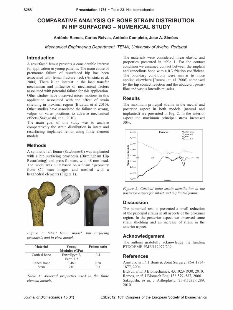
COMPARATIVE ANALYSIS OF BONE STRAIN DISTRIBUTION IN HIP SURFACING – NUMERICAL STUDY
António Ramos, Carlos Relvas, António Completo, José A. Simões
Mechanical Engineering Department, TEMA, University of Aveiro, Portugal
Introduction
A resurfaced femur presents a considerable interest
for application in young patients. The main cause of
premature failure of resurfaced hip has been
associated with femur fracture neck (Amstutz et al,
2004). There is an interest in the load transfer
mechanism and influence of mechanical factors
associated with potential failure for this application.
Other studies have observed micro motions in this
application associated with the effect of strain
shielding in proximal region (Bidytut, et al 2010).
Other studies have associated the failure to wrong,
valgus or varus positions to adverse mechanical
effects (Sakagoshi, et al, 2010).
The main goal of this study was to analyse
comparatively the strain distribution in intact and
resurfacing implanted femur using finite element
models.
Methods
A synthetic left femur (Sawbones®) was implanted
with a hip surfacing prosthesis (Birmingham Hip
Resurfacing) and press-fit stem, with 48 mm head.
The model was built based on a ScanIP geometry
from CT scan images and meshed with a
hexahedral elements (Figure 1).
Figure 1: Intact femur model, hip surfacing
prosthesis and in vitro model.
Material Young
Modulos (GPa)
Poison ratio
Cortical bone Exx=Eyy= 7,
Ezz=11.5
0.4
Cancel bone 0.480 0.28
Stem 210 0.3
Table 1: Material properties used in the finite
element models.
The materials were considered linear elastic, and
properties presented in table 1. For the contact
condition we assumed contact between the implant
and cancellous bone with a 0.3 friction coefficient.
The boundary conditions were similar to those
applied elsewhere [Ramos, et. al. 2006] composed
by the hip contact reaction and the abductor, psoas-
iliac and vastus lateralis muscles.
Results
The maximum principal strains in the medial and
posterior aspect in both models (natural and
implanted) are presented in Fig. 2. In the anterior
aspect the maximum principal stress increased
30%.
Figure 2: Cortical bone strain distribution in the
posterior aspect for intact and implanted femur.
Discussion
The numerical results presented a small reduction
of the principal strains in all aspects of the proximal
region. In the posterior aspect we observed some
strain shielding and an increase of strain in the
anterior aspect.
Acknowledgement
The authors gratefully acknowledge the funding
PTDC/EME-PME/112977/209
References
Amstutz, et al, J Bone & Joint Surgery, 86A:1874-
1877, 2004.
Bidyut, et al, J Biomechanics, 43:1923-1930, 2010.
Ramos, et al, J Biomech Eng, 138:579–587, 2006.
Sakagoshi, et al, J Arthoplasty, 25-8:1282-1289,
2010.
S288 Presentation 1736 − Topic 23. Hip biomechanics
Journal of Biomechanics 45(S1) ESB2012: 18th Congress of the European Society of Biomechanics