work sampling comparative among conventional, self assessment ...

Majlesi Journal of Electrical Engineering Vol. 13, No. 2, June 2019
57
Comparative Analysis of 12/16 Conventional and Proposed
C-core Radial Flux SRM Topologies for In-wheel Electric
Vehicle Application
Nikunj Ramanbhai Patel1*, Varsha Ajit Shah2, Makarand M. Lokhande3
1-Department of Electrical Engineering, Sardar Vallabhbhai National Institute of Technology, Surat, India.
Email: [email protected] (Corresponding author)
1-Department of Electrical Engineering, Shree Swami Atmanand Saraswati Institute of Technology, Surat, India.
2-Department of Electrical Engineering, Sardar Vallabhbhai National Institute of Technology, Surat, India.
3-Department of Electrical Engineering, Visvesvaraya National Institute of Technology, Nagpur, India.
Received: August 2018 Revised: November 2018 Accepted: January 2019
ABSTRACT:
In in-wheel Electrical Vehicle (EV) applications, Axial Flux Switched Reluctance Motor (AFSRM) is a more suitable
solution compared to Radial Flux Switched Reluctance Motor (RFSRM); due to higher outer diameter to axial length
ratio with, lower flux length and higher flux density. Switched Reluctance Motor (SRM) attract more attention due to
its Permanent Magnet (PM) free structure. In view of this, C-core RFSRM is proposed; which offers combined
advantages of radial and axial flux SRM. In this paper, based on a 12/16 pole three-phase structure, C-core RFSRM is
compared with conventional RFSRM. Average torque and phase inductance are calculated with mathematical modeling.
Computer Added Design (CAD) is verified with 2D and 3D Finite Element (FE) analysis. Based on simulation result, it
has been observed that C-core RFSRM offers higher torque compared to conventional RFSRM; with removable
wheel/rotor facility, without disturbing the stator. Prototype hardware is designed for feasibility testing of the proposed
C-core RFSRM for in-wheel EV applications.
KEYWORDS: Switched Reluctance Motor, Electrical Vehicle, Finite Element Analysis, Flux Line, Radial Field
Machine, Axial Field Machine, Advance Motor, Stepper Motor, In-Wheel Application, C-Core.
1. INTRODUCTION
Environmental and economic matters are the major
driving force in developing of EV for urban
transportation. The selection of traction motor is a key
component of EV, with rapid changing in transportation,
it increases important of comprehensive understanding
of criteria used in motor selection. Currently, Switched
Reluctance (SR) machines are predominately used in a
diversity of applications in the EV, renewable energy,
electrical aircraft, wind turbine and domestic appliances
sectors [1], [2]. SRM takes place due to the fact that there
are neither field windings nor PM used on the rotor side.
As a result, the SRM is low cost and have simple and
robust rotor structure compared to other electrical
motors. Due to its merits, it is suitable for harsh
environment and safety-critical applications. In addition,
SRM offers simple structure, ruggedness, high starting
torque, fault tolerance ability, high-speed operation, and
low manufacturing cost [3-5].
Since 2000, onwards SRM is found suitable for EV.
In [6] comparison of different conventional and non-
conventional electrical machines for EV applications are
presented. First SR motor was used in hybrid electrical
vehicle by [7], but significant vibration issues are there.
In papers [8], [9], the influence of various stator pole and
yoke shapes was investigated and a less vibration
structure for 8/6 SRM was proposed. In papers [10], [11]
higher torque was achieved by shark pole surface
topology and C-core stator design. In [12], duel rotor E-
shaped topology is proposed with 20% more torque, but
it is bulky structure.
Till now, in EV application 20 to 30 % efficiency is
reduced due to mechanical gear system. So as a solution
of this, in-wheel motor technique [13] has been come in
to the service and motor is developed with new name of
“outer rotor hub machine” [14]. In this design stator is
situated inside of rotor with stator winding. It has limited
space for stator winding with poor heat dissipation.
SRM is operating in step so it is also known stepper
motor. Due to step operation, there is a torque ripple [15]
so for reducing it, axial flux technique [16] comes into
the practice.
In axial flux topology, segmented and tooth types
poles are mainly developed by [17-19]. Segmented SRM
design and FEM Analysis for 3-phase 6/4 pole is
proposed in [20]. SRM is a purely magnetic concept so

Majlesi Journal of Electrical Engineering Vol. 13, No. 2, June 2019
58
torque is depending on the setup of number of magnetic
line. In [21-24], magnetic analysis of SRM is proposed
by mathematical and FE modeling. In [25], prototype
model of axial field motor is developed and the issues of
low inductance ratio, due to higher leakage flux in SRM
by different methods are elicited. In [26-31] various
radial and axial flux design techniques has been
discussed, for the reduction of torque ripple in SR
machines.
Based on this survey, it can be concluded that, by
using appropriate control strategy or increasing
stator/rotor poles or phase numbers with suitable design
technique, torque ripple can be reduced. Issues regarding
low power, lower torque density, higher torque ripple
and noise are still major challenges in SRM. Several
efficacious methods have been investigated to improve
the SRM drive system and make it more effective for EV
application.
A C-core 12/15 RFSRM was earlier presented in [32]
by the author. The same C-core 12/15 RFSRM design is
extended in [33] with some required modification by
help of mathematical modeling and verified with FEM
analysis. A prototype structure of the motor is fabricated,
tested and verified with simulation results. This structure
has odd number of rotor poles in rotor. In-general odd
number of rotor/stator poles are not preferable for
conventional radial field motor structure due to magnetic
field unbalancing, and it is a limitation of conventional
radial field structure.
In this paper, 12/16 pole structure is adopted in place
of 12/15 pole for comparing design of conventional
RFSRM with design of proposed C-core RFSRM. This
paper is arranged as follow:
Electrical dynamics of vehicle, basic machine
parameters and magnetic analysis with detailed
mathematical modeling for conventional and proposed
C-core RFSRM are given in section 2. The geometry
comparison of both topologies is also covered in this
section. FEM analysis and results of both topologies are
compared in section 3. Section 4 contains the
conclusion.
2. GEOMETRY AND PARAMETER SELECTION
Flux is perpendicular to the rotating axis in radial
flux machine and parallel in axial flux machine. To make
the comparison between two radial structures, several
parameters are held constant or very near to each other.
Complete 3D view of 12/16 pole conventional and C-
core RFSRM structures are shown in Fig. 1. To improve
the torque density and efficiency with reduction in
torque ripple, 12/16 pole SRM configuration is
considered. The proposed C-core radial flux machine is
designed first to provide the benchmark and then the
design of the conventional radial flux machines is
attempted.
(a) (b)
Fig. 1. 3D view of 12/16 (a) conventional RFSRM (b)
proposed C-core RFSRM.
The proposed C-core RFSRM has following merits
against conventional RFSRM.
1. All stator cores are magnetically and electrically
isolated from each other so it is very easy to wound
and maintain.
2. More space available for wound the coils, so it is
easy to increase the number of turns.
3. C-core design offers maximum heat dissipation
because, the coils are located at outer
circumferences. Additional cooling facilities are
possible to provide due to the surface mounting.
4. Higher power and torque density: In Proposed C-
core RFSRM design, it is easy to increase the radius
without increasing the length of magnetic flux line.
As a result torque will be increased.
5. Coil length is reduced, due to lower axial length of
machine compared to conventional RFSRM. Price
will be reduced.
6. Proposed C-core RFSRM structure is fit for in-
wheel application for EV. During the maintenance,
wheel can be removed by removing four bolts, just
like existing vehicle system without disturbing the
stator. It is a unique feature of proposed C-core
RFSRM over conventional SRM.
7. All time flux is set-up in one direction so reducing
the magnetic losses, which occurs due to residual
magnetism.
Fig. 2 shows complete geometrical details in Two
Dimensional (2D) view. In both of case, stator has 12
pole and rotor has 16 pole. The 12 core of stator carried
individual winding which are excited by 3 phases in
group on 4 coil. Coils of each phase can be connected in
series or parallel. The outer diameter of rotor D0 is 304
mm. For both types of RFSRM, same area of air-gap is
considered as shown in Fig. 3. Rotor teeth/pole length is
considered same for similar wind-age losses. The other
dimensions like rotor pole arc βr, stator pole arc βs, air-
gap length lg, diameter of shaft Ds and axial length of
motor are considered same for both cases.

Majlesi Journal of Electrical Engineering Vol. 13, No. 2, June 2019
59
In conventional RFSRM, all rotor poles are part of
the single rotor and all stator poles are part of single
stator. However, in proposed C-core RFSRM all stator
cores and all rotor poles are magnetically and electrically
isolated from each other as shown in Fig. 1. CRNO M-
45 steel material is considered for all stator and rotor
pole. In C-core RFSRM, additionally aluminium disc is
required to support the stator cores and rotor poles. The
design dimensions are given in Table 1, where some
dimensions are assumed based on survey, some are
derived by mathematical equation and other are
optimized.
(a) (b)
(c)
Fig. 2. Two dimensional geometric details of (a)
conventional RFSRM, (b) proposed C-core RFSRM,
and (c) single C-core of proposed C-Core RFSRM.
The design procedure of both topologies is divided
into three parts. In the first part, required torque and
power are calculated using vehicle dynamic equation. In
the second part, the three basic SRM condition and
optimized number of stator and rotor poles with arc
length are checked by feasible triangle. In the third part,
excitation parameters and torque are calculated by using
magnetic analysis.
Table 1. Design dimension and rating of conventional
and proposed C-core RFSRM.
Parameter Conventional
RFSRM
Proposed
C-core
RFSRM
Number of stator pole, Ns 12
Number of rotor pole, Nr 16
Number of phases, q 3
Outer diameter of rotor,
Dor 304 mm
Inner diameter of rotor, Dir 256 mm
Total axial length of motor,
L 100+AL mm
Air-gap length, lg 0.5 mm
Diameter of shaft, Ds 80 mm
Rotor pole pitch, βpr 22.50
Stator pole pitch, βps 300
Stator pole arc, βs 90
Rotor pole arc, βr 90
Stator core length, ls - 105 mm
Stator core width, ws - 100 mm
Rotor pole length, lr 24 mm
Rotor pole width, wrp 30 mm
Stator pole length, lsp 10 mm
Stator pole width, wsp 30 mm
Coil width, wc 40 mm
No. of turns per pole 65
Width of stator yoke, Wsy
Depend on
length of
stator pole
arc
Stator
core
work as
a stator
yoke
(for
Individu
al core )
Rated Speed, N 600 r/min
Rated current, I 40 A
Input voltage, V 120 V
(a) (b)
Fig. 3. Air-gap view of (a) Conventional RFSRM, and
(b) C-core RFSRM.

Majlesi Journal of Electrical Engineering Vol. 13, No. 2, June 2019
60
2.1. Modelling of Electrical Vehicle Dynamic
Comparison of two RFSRM is proposed for EV
application. Hence the vehicle dynamic parameters need
to be considered for the design of RFSRM. The torque
demand of vehicle is obtained from the vehicle dynamic
equation (1) to design motor. The vehicle torque
demanded Tm is a summation of rolling friction, air drag
force, effective weight, acceleration and angular
acceleration force that is [34]
1 2( cos
2
sin )2
T mg v ACm d
dv Jmg m a r
dt r
(1)
Where
r : radius of wheel which is 450 mm
μ : coefficient of rolling friction which is
0.0007
ωm : speed of motor which is 60 km/h (ωm=v/r)
Cd : drag coefficient which is 0.7
ρ : density of air
A : frontal surface area
v : velocity
ψ : inclination angle
m : mass of vehicle that is 120 kg (for two
wheeler)
a: acceleration
As per Indian driving cycle (IDC), acceleration of 0-
50 km/h in 20s and speed of 60 km/h are considered.
Power requirement of motor is 1.6 kW and torque
requirement is 26 N.m. as per vehicle dynamic
modelling.
2.2. Rotor and Stator Pole Arc Selection
The number of rotor poles and stator poles are
arranged in such a way that, when a phase is energized,
rotor must be aligned with the particular phase. At the
same time other phase must be in unaligned condition
with other rotor pole. So when next phase is energized,
the new stable position can be achieved. SRM’s
condition (2), (3) and (4) are summarized and illustrated
by feasible zones as shown in Fig. 4, for 12/16 pole
RFSRM. Where these three conditions must be satisfied
for selected number of rotor and stator pole to achieve
the self-starting with lower torque ripple and good
average torque.
360N N
r s
sN Nr s
(2)
360-
r sNr
(3)
r s
(4)
Fig. 4. Feasible zone for stator and rotor pole arc.
Still the feasible zone XYZ is quite big to decide the
correct value of stator pole arc βs and rotor pole arc βr.
According to pulsating field theory of machines, the
rotor pole arc is considered 90. It is 40 % of rotor pole
pitch for maximizing the difference of aligned and
unaligned inductance. Now βs should be less than or
equal to 90 (4). After the detailed study and based on
optometric result, the stator pole arc is considered 90.
Finally, 7.50 step angle is finalized based on feasible
triangle to get the highest value of torque with minimum
torque ripple. Here dwell angle (βr - βs ) is considered
zero because small dwell angles in min Inductance (L)
and max L regions are desirable in L(θ)- θ profile as
shown in Fig. 5.
Fig. 5. Idealistic L-θ profile for 12/16 RFSRM.
Majlesi Journal of Electrical Engineering Vol. 13, No. 2, June 2019
61
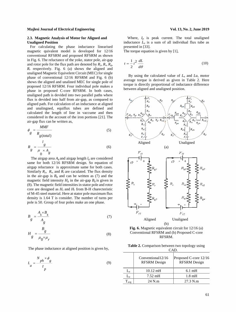
2.3. Magnetic Analysis of Motor for Aligned and
Unaligned Position
For calculating the phase inductance linearised
magnetic quivalent model is developed for 12/16
conventional RFSRM and proposed RFSRM as shown
in Fig. 6. The reluctance of the yoke, stator pole, air-gap
and rotor pole for the flux path are denoted by Ry, Rs, Rg,
Rr respectively. Fig. 6 (a) shows the aligned and
unaligned Magnetic Equivelent Circuit (MEC) for single
phase of conventional 12/16 RFSRM and Fig. 6 (b)
shows the aligned and unalined MEC for single pole of
praposed 12/16 RFSRM. Four individual pole makes a
phase in proposed C-core RFSRM. In both cases,
unaligned path is devided into two parallel paths where
flux is devided into half from air-gap, as compared to
aligned path. For calculation of an inductance at aligned
and unalingned, equiflux tubes are defined and
calculated the length of line in vaccume and then
considered in the account of the iron portions [21]. The
air-gap flux can be written as,
( )
MMF
g Rg total
(5)
0
lg
Rg A
g
(6)
The airgap area Ag and airgap length lg are considered
same for both 12/16 RFSRM design. So equation of
airgap reluctance is approximate same for both cases.
Similarly Ry, Rs, and Rr are caculated. The flux density
in the air-gap is Bg and can be written as (7) and the
magnetic field intensity Hg in the air-gap Bg is given in
(8). The magnetic field intensities in stator pole and rotor
core are designed as Hs and Hr from B-H charecteristic
of M-45 steel material. Here at stator pole maximum flux
density is 1.64 T is consider. The number of turns per
pole is 50. Group of four poles make an one phase.
A Bs sB
g Ag
(7)
0
Bg
Hg
r
(8)
The phase inductance at aligned position is given by,
Nph g
La I
p
(9)
Where, Ip is peak current. The total unaligned
inductance Lu is a sum of all individual flux tube as
presented in [33].
The torque equation is given by [1],
1 2
2
dLt i
d (10)
By using the calculated value of La and Lu, motor
average torque is derived as given in Table 2. Here
torque is directly proportional of inductance difference
between aligned and unaligned position.
Aligned Unaligned
(a)
Aligned Unaligned
(b)
Fig. 6. Magnetic equivalent circuit for 12/16 (a)
Conventional RFSRM and (b) Proposed C-core
RFSRM.
Table 2. Comparison between two topology using
CAD.
Conventional12/16
RFSRM Design
Proposed C-core 12/16
RFSRM Design
La
10.12 mH 6.1 mH
Lu
7.52 mH 1.8 mH
Tavg 24 N.m 27.3 N.m

Majlesi Journal of Electrical Engineering Vol. 13, No. 2, June 2019
62
3. FINITE ELEMENT MODEL OF BOTH 12/16
RFSRM
Conventional and proposed C-core 12/16 RFSRM
geometries are prepared and analyzed using
MAXWELL 2D and 3D FE software. Main dimensions
are chosen based on mathematical modeling and
analysis as shown in Table 1. Both of the machine’s
rotor and stator are made by laminated steel stamping.
Due to dynamic model and for reducing the simulation
time, special care has been taken when assigning mesh.
The mesh is assigned in 2D and 3D model as shown in
Fig. 7. The status of magnetic flux density at the
different parts in stator and rotor pole along with air-gap
is shown in Fig. 8. The magnetic flux setup path of
conventional RFSRM is longer than proposed C-core
RFSRM with same excitation. For proper comparison,
6400 AT MMF/phase is considered in both cases.
(a) (b)
Fig. 7. Meshing in (a) 2D model of conventional
RFSRM and (b) 3D model of proposed C-core
RFSRM.
Based on FEM analysis, the average value of air-gap
flux density is 1.64 T. In conventional RFSRM,
magnetic flux is set-up through two pole and in proposed
C-core RFSRM, magnetic flux is setup in individual
pole. No additional yoke structure is needed in the
proposed C-core RFSRM. Simulated value of aligned
inductance and unaligned inductance with average
torque of conventional RFSRM and proposed C-core
RFSRM are given in Table 3.
(a)
(b)
(c)
Fig. 8. Magnetic flux density and field plot of (a)
Conventional RFSRM for aligned condition (b)
Conventional RFSRM for unaligned condition (c)
Proposed C-core RFSRM for single core.
Table 3. Comparison between two topologies by using
FEM.
Conventional 12/16
RFSRM Design
Proposed C-core 12/16
RFSRM Design
La 10.05 mH 6.21 mH
Lu 7.51 mH 1.72 mH
Tavg 24.12 N.m 27.4 N.m
The comparison of magnetic characteristics of
conventional RFSRM and proposed C-core RFSRM is
shown in Fig. 9. In the proposed C-core RFSRM, 20%
lesser steel material is required compared to
conventional RFSRM. For supporting 12 stator core and
15 rotor pole, additionally non-magnetic material
(aluminum) is required in C-core RFSRM. It increases
the overall weight of C-core RFSRM compared to
conventional RFSRM. In C-core topology, pole
windings is divided into two limb, which provide more
winding space with good heat dissipation area.
Fig. 9. Magnetic flux density

Majlesi Journal of Electrical Engineering Vol. 13, No. 2, June 2019
63
Fig. 10. Comparison of current profile and torque
profile for single phase.
It is observed that proposed C-core RFSRM offers
good torque due to good aligned to unaligned inductance
ratio. It is nearest to 12% higher than conventional
RFSRM at rated current as shown in Fig. 10. The step
angle of motor is considered 7.50 based on rotor and
stator pole arc. After every 7.50, next phase needs to be
energized to achieve the aligned condition to concern
phase pole. For exiting the motor, three different phases
are exited sequentially by using position sensors.
Fig. 11. Comparison of individual phase torque plot
between conventional RFSRM and proposed C-core
RFSRM.
Fig. 11 shows the comparison between 12/16
Conventional and C-core RFSRM, based on torque
characteristics. Where suddenly current fall is noticed at
the time of switching the phase.
Fig. 12 shows the variation in torque at different speed
of motors. The optimized torque is 27.4 N.m for C-core
RFSRM and 24.12 N.m for conventional RFSRM at 600
r/min speed. Fig. 12 shows higher torque with wide
speed range at constant power operation around 2-3
times the base speed. In this, before base speed region is
representing constant torque zone and after base speed
region is representing constant power zone up to the
critical speed.
Fig. 12. Comparison of torque on different speed.
After the critical speed torque and power, both are
decreased as shown in Fig. 12. The SRM is designed for
rated input power capacity of 2.53 kW. For constant
torque operation, controller plays the major role. The
efficiency map of motor at various speed are given in
Fig. 13, it compares two machines based on efficiency.
C-core RFSRM is 5% more efficient than conventional
RFSRM at rated condition.
Fig. 13. Comparison of efficiency.
4. IN-WHEEL SUTABILITY FOR ELECTRICAL
VEHICLE
In order to improve the efficiency of electrical vehicle,
in-wheel motors are mandatory for eliminating the need
of a gear box. It also reduces the utilization of space,
which increases the compactness. The main features of
in-wheel technology is high power density and high
efficiency along with rugged construction. Fig. 14 (a)
shows the complete view of conventional RFSRM with
in-wheel arrangement. In this type of arrangement,
wheel is mounted on shaft so torque is reduced. For
increasing the torque, gear mechanism is mandatory in
such types of inner rotor SRM.

Majlesi Journal of Electrical Engineering Vol. 13, No. 2, June 2019
64
(a) (b)
Fig. 14. (a) Complete view of conventional RFSRM
with wheel arrangement. (b) Outer rotor arrangement of
conventional 12/16 RFSRM.
(a) (b)
Fig. 15. Complete (a) view of C-core RFSRM with
removable wheel/rotor arrangement. (b) Proto type
hardware arrangement of C-core RFSRM.
By transferring rotor at outer periphery, it is possible
to implement in-wheel arrangement in conventional
RFSRM as shown in Fig. 14 (b). In this type of
arrangement, the biggest limitation is small winding
space and poor heat dissipation, which is not preferable
for higher current density motor. As compared to
conventional RFSRM, the proposed C-core RFSRM
offers removable wheel structure without disturbing
stator. It provides good winding space and heat
dissipation area which improve the power handling
capability of machine at higher torque and speed. Fig. 15
(a) shows the complete arrangement of 12/16 C-core
RFSRM with in-wheel implementation and Fig. 15 (b)
shows the complete hardware with removable wheel
structure. In this, wheel/rotor can be removed without
disturbing the stator or stator winding. The 12/15 C-core
RFSRM hardware is developed and tested by author in
[33]. By using same mathematical modeling 12/16 C-
core RFSRM is designed and compared with
conventional RFSRM and prove that proposed design is
more feasible for in- wheel electrical vehicle application
with special merits.
5. CONCLUSION
A novel C-core RFSRM topology is compared with
conventional RFSRM for 12/16 pole structure. It has
found that C-core RFSRM offers smaller axial length,
shorter and independent magnetic flux path, good heat
dissipation and easy maintenance with removable
rotor/wheel structure. Proposed C-core design offers
12% higher torque, 5% higher efficiency and 20% lower
steel consumption compare to conventional RFSRM.
This C-core RFSRM is a potential candidate for
electrical vehicle application due to its in-wheel
arrangement and higher torque and power density.
REFERENCES [1] T. J. E. Miller, “Optimal Design of Switched
Reluctance Motors,” IEEE Trans. Ind. Electron., Vol.
49, No.1, pp. 15–27, Feb. 2002.
[2] A. L. M. d. Santos, J. Anthonis, F. Naclerio, J. J. C.
Gyselinck, H. V. d. Auweraer, and L. C. S. Goes,
“Multiphysics NVH Modeling: Simulation of A
Switched Reluctance Motor for an Electric
Vehicle,” IEEE Trans. Ind. Electron., Vol. 61, No. 1,
pp. 469–476, Jan. 2014.
[3] M. Takeno, A. Chiba, N. Hoshi, S. Ogasawara, M.
Takemoto, and M. A. Rahman, “Test Results and
Torque Improvement of the 50-kW Switched
Reluctance Motor Designed for Hybrid Electric
Vehicles,” IEEE Trans. Ind. Appl., Vol. 48, No. 4, pp.
1327–1334, Jul./Aug. 2012.
[4] H. Chen and J. J. Gu, “Switched Reluctance Motor
Drive with External Rotor for Fan in Air
Conditioner,” IEEE/ASME Trans. Mechatronics,
Vol. 18, No. 5, pp. 1448–1458, Oct. 2013.
[5] V. Valdivia, R. Todd, F. J. Bryan, A. Barrado, A.
Lazaro, and A. J. Forsyth, “Behavioral Modeling of a
Switched Reluctance Generator for Aircraft Power
Systems,” IEEE Trans. Ind. Electron., Vol. 61, No. 6,
pp. 2690–2699, Jun. 2014.
[6] W. Xu, J. Zhu, Y. Guo, “Applied Superconductivity
and Electromagnetic Devices,” Proceedings of 2009
IEEE International Conference on Chengdu China,
Sept., 2009.
[7] Lovatt, H.C. “Optimization of Switched Reluctance
Motors for Hybrid Electric Vehicles,” Power
Electronics, Machines and Drives, International
Conference, Publ. No. 487, pp. 177 – 182, 2002.
[8] J. Hong “Stator Pole and Yoke Design for Vibration
Reduction of Switched Reluctance Motor,” IEEE
Trans. on Magn., Vol. 38, No. 2, March 2002, pp. 929.
[9] Jian Li, Xueguan Song, “Comparison of 12/8 and 6/4
Switched Reluctance Motor: Noise and Vibration
Aspects,” IEEE Trans. on Magn., Vol. 44, N0. 11,
Nov. 2008, pp. 4131.
[10] J. Corda, A.M. Tataru, P.O. Rasmussen and E. Ritchie,
“Analytical Estimation of Torque Enhancement of
the SR Machine with Saw-Shaped (Shark) Pole
Surfaces,” IEE Proc.-Electr. Power Appl., Vol. 151,
No. 2, March 2004.
[11] Sh. H. Mao, M. Ch. Tsai, “Novel Switched
Reluctance Motor with C-Core Stators,” IEEE
Transactions on Magn, Vol. 41, No. 12, pp. 413, Dec.
Majlesi Journal of Electrical Engineering Vol. 13, No. 2, June 2019
65
2005.
[12] W. Yang, “Design and Research of a New Dual-
Rotor Switched Reluctance Motor for Hybrid
Electric Vehicles,” Electrical Machines and Systems
(ICEMS), International Conference, pp. 829 – 833,
2010.
[13] W. Yaling, “Outer-rotor Switched Reluctance
Motor and Its Control System Used in Electric
Vehicles”, Electrical Machines and Systems (ICEMS),
International Conference, pp. 1 – 4, 2011.
[14] Sakthivel, P., “Design of a 250 w, Low Speed
Switched Reluctance Hub Motor for Two
Wheelers,” Electrical Energy Systems (ICEES), 1st
International Conference, pp. 176 – 181,2011.
[15] R. Madhavan and B.G. Fernandes, “A Novel
Technique for Minimizing Torque Ripple in Axial
Flux Segmented Rotor SRM,” IEEE Conference,
Energy Conversion Congress and Exposition (ECCE),
pp. 3383 – 3390, 2011.
[16] B. G. Fernandes, “A Novel Axial Flux Segmented
SRM for Electric Vehicle Application,” XIX
International IEEE Conference on Electrical
Machines – ICEM, pp 1-6. Sept. 2010.
[17] S. Khaliq, M. Modarres, Thomas A. Lipo, “Design of
Novel Axial-Flux Dual Stator Doubly Fed
Reluctance Machine,” IEEE Trans. on magn., Vol.
51, No. 11, pp. 804-807, Nov. 2015
[18] Fernandes B.G., “Comparative Analysis of Axial
Flux SRM Topologies for Electric Vehicle
Application,” Power Electronics, Drives and Energy
Systems (PEDES), IEEE International Conference, pp.
1 – 6, Dec.2012.
[19] Madhavan R., “Axial Flux Segmented SRM with a
Higher Number of Rotor Segments for Electric
Vehicles,” Energy Conversion, IEEE Transactions,
Vol. 28, No. 1, pp. 203 – 213, 2013.
[20] W. Qinghai, H. Xiaofeng, J. Defei, W. Shasha, Z. Tao,
“Parameter Design and FEM Analysis for 3-phase
6/4 Poles Switched Reluctance Motor,” Proceedings
of the 30th Chinese Control Conference, July 2011.
[21] P. Vijayraghavan, “Design of Switched Reluctance
Motors and Development of a Universal Controller
for Switched Reluctance and Permanent Magnet
Brushless DC Motor Drives,” PhD Report,
Blacksburg, Virginia, Nov. 2001.
[22] Ragavan, K., Prathamesh, J., “A Novel Magnetic-
Circuit Based Design Approach for Electric Vehicle
Motors,” Electric Vehicle Conference (IEVC), IEEE
International, pp. 1 – 5, 2012,
[23] W. Ding, Zh. Yin, Ling Liu, “Magnetic Circuit
Model and Finite-Element Analysis of a Modular
Switched Reluctance Machine with E-Core Stators
and Multi-Layer Common Rotors,” Published in
IET Electric Power Applications, March 2014. ISSN
1751-8660.
[24] T. Kellerer, O. Radler, “Axial Type Switched
Reluctance Motor of Soft Magnetic Composite,” Innovative Small Drives and Micro-Motor Systems,
GMM/ETG Symposium, pp. 1 – 6, 2013.
[25] A. Labak, Narayan C. Kar, “Novel Approaches
Towards Leakage Flux Reduction in Axial Flux
Switched Reluctance Machines,” IEEE Trans. on
Magn, Vol. 49, No. 8, Aug. 2013.
[26] Chiba, Y. Takano, M. Takeno, T. Imakawa, N. Hoshi
M. Takemoto, and S. Ogasawara, “Torque Density
and Efficiency Improvements of a Switched
Reluctance Motor Without Rare-Earth Material
for Hybrid Vehicles,” IEEE Trans. Ind. Appl., vol. 47,
no. 3, pp. 1240–1246, May/Jun. 2011.
[27] Y. K. Choi, H. S. Yoon, and C. S. Koh, “Pole-shape
Optimization of a Switched-Reluctance Motor for
Torque Ripple Reduction,” IEEE Trans. Magn., Vol.
43, No. 4, pp. 1797–1800, Apr. 2007.
[28] J. Li, X. Song, and Y. Cho, “Comparison of 12/8 and
6/4 Switched Reluctance Motor: Noise and
Vibration Aspects,” IEEE Trans. Magn., Vol. 44, No.
11, pp. 679–686, Nov. 2008.
[29] A. Siadatan, E. Afjei, “An 8/6 Two Layers Switched
Reluctance Motor: Modeling, Simulation and
Experimental Analysis,” Majlesi Journal of
Electrical Engineering, Vol. 6, No. 1, March 2012.
[30] T. Higuchi, K. Ueda, and T. Abe, “Torque Ripple
Reduction Control of a Novel Segment Type SRM
with 2-steps Slide Rotor,” in Proc. IEEE Int. Power
Electron. Conf., pp. 2175–2180, Jun. 2010.
[31] B. Bilgin, A. Emadi, and M. Krishnamurthy,
“Comprehensive Evaluation of the Dynamic
Performance of a 6/10 SRM for Traction
Application in PHEVs,” IEEE Trans. Ind. Electron.,
Vol. 60, No. 7, pp. 2564–2575, Jul. 2013.
[32] Nikunj R. Patel, Varsha A. Shah, and Makarand M
Lokhande “Design and Performance Analysis of
Axial Flux C-Core Switched Reluctance Motor for
In-Wheel Electrical Vehicle Application,” IEEE
ITEC Conference, pp 1– 6, June-2016.
[33] Nikunj R. Patel, Varsha A. Shah, and Makarand M
Lokhande “A Novel Approach to the Design and
Development of 12/15 Radial Field C-core Switched
Reluctance Motor for Implementation in Electric
Vehicle Application,” IEEE Transactions on
Vehicular Technology, May-2018 [Online Available].
[34] Larminie, J. and Lowry, J., “Electric Vehicle
Technology Explained,” John Wiley and Sons ltd, pp.
186–192, 2003.


