COMPARASION OF PREDICTION AND MEASUREMENT METHODS FOR...
13
FACTA UNIVERSITATIS Series: Architecture and Civil Engineering Vol. 10, N o 2, 2012, pp. 155 - 167 DOI: 10.2298/FUACE1202155P COMPARASION OF PREDICTION AND MEASUREMENT METHODS FOR SOUND INSULATION OF LIGHTWEIGHT PARTITIONS UDC 699.844:624.3 Momir Praščević, Dragan Cvetković, Darko Mihajlov University of Niš, Faculty of Occupational Safety of Niš, Serbia, [email protected] Abstract. It is important to know the sound insulation of partitions in order to be able to compare different constructions, calculate acoustic comfort in apartments or noise levels from outdoor sources such as road traffic, and find engineer optimum solutions to noise problems. The use of lightweight partitions as party walls between dwellings has become common because sound insulation requirements can be achieved with low overall surface weights. However, they need greater skill to design and construct, because the overall design is much more complex. It is also more difficult to predict and measure of sound transmission loss of lightweight partitions. There are various methods for predicting and measuring sound insulation of partitions and some of them will be described in this paper. Also, this paper presents a comparison of experimental results of the sound insulation of lightweight partitions with results obtained using different theoretical models for single homogenous panels and double panels with and without acoustic absorption in the cavity between the panels. Key words: sound insulation, lightweight partitions, transmission loss. 1. INTRODUCTION In many situations it may not be feasible to modify the characteristics of the noise sources. In these cases, a possible solution to a noise problem it to modify the acoustic transmission path or the paths between the noise source and the receiver. In such a situa- tion the first task for the noise-control purposes is to determine the relevance quantities. The quantities that define the acoustical quality of constructions in buildings are airborne Received May 14, 2012 Acknowledgement: This research is part of the project “Development of methodology and means for noise protection from urban areas” (No. TR-37020) and “Improvement of the monitoring system and the assessment of a long-term population exposure to pollutant substances in the environment using neural networks“ (No. III- 43014). The authors gratefully acknowledge the financial support of the Serbian Ministry for Education and Science for this work.
Transcript of COMPARASION OF PREDICTION AND MEASUREMENT METHODS FOR...

FACTA UNIVERSITATIS Series: Architecture and Civil Engineering Vol. 10, No 2, 2012, pp. 155 - 167 DOI: 10.2298/FUACE1202155P
COMPARASION OF PREDICTION AND MEASUREMENT METHODS FOR SOUND INSULATION OF LIGHTWEIGHT
PARTITIONS
UDC 699.844:624.3
Momir Praščević, Dragan Cvetković, Darko Mihajlov
University of Niš, Faculty of Occupational Safety of Niš, Serbia, [email protected]
Abstract. It is important to know the sound insulation of partitions in order to be able to compare different constructions, calculate acoustic comfort in apartments or noise levels from outdoor sources such as road traffic, and find engineer optimum solutions to noise problems. The use of lightweight partitions as party walls between dwellings has become common because sound insulation requirements can be achieved with low overall surface weights. However, they need greater skill to design and construct, because the overall design is much more complex. It is also more difficult to predict and measure of sound transmission loss of lightweight partitions. There are various methods for predicting and measuring sound insulation of partitions and some of them will be described in this paper. Also, this paper presents a comparison of experimental results of the sound insulation of lightweight partitions with results obtained using different theoretical models for single homogenous panels and double panels with and without acoustic absorption in the cavity between the panels.
Key words: sound insulation, lightweight partitions, transmission loss.
1. INTRODUCTION
In many situations it may not be feasible to modify the characteristics of the noise sources. In these cases, a possible solution to a noise problem it to modify the acoustic transmission path or the paths between the noise source and the receiver. In such a situa-tion the first task for the noise-control purposes is to determine the relevance quantities. The quantities that define the acoustical quality of constructions in buildings are airborne
Received May 14, 2012 Acknowledgement: This research is part of the project “Development of methodology and means for noise protection from urban areas” (No. TR-37020) and “Improvement of the monitoring system and the assessment of a long-term population exposure to pollutant substances in the environment using neural networks“ (No. III-43014). The authors gratefully acknowledge the financial support of the Serbian Ministry for Education and Science for this work.

M. PRAŠČEVIĆ, D. CVETKOVIĆ, D. MIHAJLOV 156
and impact sound insulation between rooms, airborne sound insulation of facades, rever-beration time of rooms and noise level caused by noise source.
Airborne sound insulation is the most important physical quantity defining the acous-tical quality of buildings. Depending on the activities in the rooms, it may be necessary to place sound insulation requirements to the party walls, either to isolate the room from the neighboring noisy spaces or vice versa.
The use of lightweight partitions as party walls between dwellings has become com-mon because sound insulation requirements can be achieved with low overall surface weights. These partitions can be built by using a single frame partition or, when high sound insulation is required, by using a double frame partition. Choosing a suitable com-bination of gypsum board layers, air cavity and sound absorbing material thickness, dou-ble frame partitions with a high sound transmission loss can be achieved. Compared with traditional masonry constructions, they are lighter, easier and quicker to assemble, and leave a cleaner building site. However, they need greater skill to design and construct, be-cause the overall design (including strength, stiffness, and buckling) is much more com-plex. It is also more difficult to predict sound transmission loss.
Laboratory measurements can be made for many different types of partitions, but it is impractical to test every possible design and so it is necessary to have reliable methods for predicting the sound transmission loss of typical building constructions.
In this paper, a general overview of the prediction models of sound insulation will be presented. Also, this paper presents a comparison of experimental measurements of the sound insulation of lightweight partitions with theoretical models. Single homogeneous panels are examined first, with mass, stiffness, damping and panel size found to be ade-quate to describe most common building constructions. Double panel are then examined, with additional factors of airgap between the panels, connections between the panels and acoustic absorption in the cavity enabling good engineering predictions of sound trans-mission loss.
2. SOUND TRANSMISSION LOSS
When sound is incident upon a wall or partition some of it will be reflected and some will be transmitted through the wall. The fraction of incident energy which is transmitted is called the transmission coefficient . As values of the transmission coefficient are mainly small the logarithmic index of sound transmission, the transmission loss (some-times referred as sound reduction index R), is used to quantity transmitted energy. The transmission loss is defined as [1]:
10 log [dB]TL (1)
The transmission coefficient and thus the sound transmission loss depend upon the an-gle of sound incidence and therefore the following terms have been commonly used: nor-mal incidence, diffuse field incidence and field incidence sound transmission loss. Field incidence sound transmission loss is commonly observed in measurement and prediction methods.
Comparasion of Prediction and Measurement Methods for Sound Insulation of Lightweight Partitions 157
2.1. Single panels
Single panels can be divided into four main types: thin panels, corrugated (profiled) panels, stiffened (ribbed) panels and thick monolithic walls. The main physical factors controlling the sound transmission through impervious single panels are [2]: surface mass, which is mainly responsible for the forced vibration, bending stiffness, which together with surface mass determines the critical fre-
quency of the panel, dimensions, which together with bending stiffness and surface mass determine the
lowest natural resonances (normal modes) of the panel, loss factor, which determines the amplitude of resonant vibration, and sound incidence angle.
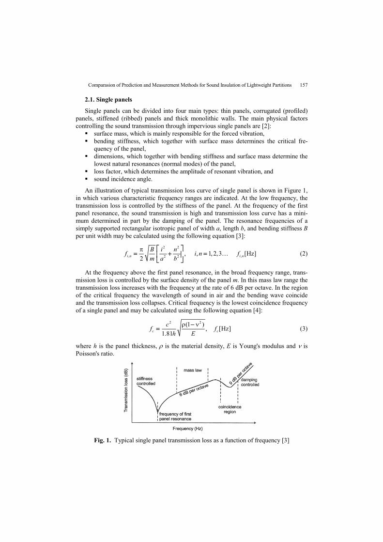
An illustration of typical transmission loss curve of single panel is shown in Figure 1, in which various characteristic frequency ranges are indicated. At the low frequency, the transmission loss is controlled by the stiffness of the panel. At the frequency of the first panel resonance, the sound transmission is high and transmission loss curve has a mini-mum determined in part by the damping of the panel. The resonance frequencies of a simply supported rectangular isotropic panel of width a, length b, and bending stiffness B per unit width may be calculated using the following equation [3]:
2 2
, ,2 2, , 1, 2,3 [Hz]
2i n i n
B i nf i n f
m a b
(2)
At the frequency above the first panel resonance, in the broad frequency range, trans-mission loss is controlled by the surface density of the panel m. In this mass law range the transmission loss increases with the frequency at the rate of 6 dB per octave. In the region of the critical frequency the wavelength of sound in air and the bending wave coincide and the transmission loss collapses. Critical frequency is the lowest coincidence frequency of a single panel and may be calculated using the following equation [4]:
2 2(1 )
, [Hz]1.81c c
cf f
h E
(3)
where h is the panel thickness, is the material density, E is Young's modulus and is Poisson's ratio.
Fig. 1. Typical single panel transmission loss as a function of frequency [3]

M. PRAŠČEVIĆ, D. CVETKOVIĆ, D. MIHAJLOV 158
At and above the critical frequency, resonant vibration determines the sound transmis-sion coefficient. This is called the stiffness-controlled region where the slope of the transmission loss curve is 9 dB per octave. The transmission loss rises and gradually ap-proaches an extension of the original mass law portion of the curve.
2.2. Double panels
Theoretical and experimental analysis of sound transmission through single panels show that the transmission loss increases by 5-6 dB per doubling of mass. High transmis-sion loss can be provided by double panels composed of two separate panels separated by airspace. Sound absorbing material can be placed in the airspace of double panels and their principal function is to suppress acoustic resonances of the airspace [1].
There are two major paths by which sound energy is transmitted through a double panel: the first involves radiation from the first panel into the airspace, where it excites the second panel; the second involves structure borne transmission of vibrational energy from the first panel to the second panel through mechanical links between the panels [5].
Sound transmission through double panels is more complex because a mass-air-mass resonance [1],
2
00 0
1 2
1 1 1, [Hz]
2
cf f
d m m
, (4)
and cavity resonances [4],
, [Hz]2k k
cf k f
d , (5)
can seriously affect the transmission loss of the double panels (d is the distance between the inner surfaces of double panels). In practice, it is necessary to introduce an empirical factor 1.8 into equation (4) to give better agreement with existing data for ordinary wall construction [3].
An illustration of typical transmission loss curve of double panels is shown in Figure 2, in which various characteristic frequency ranges are indicated.
Fig. 2. Typical double panel transmission loss as a function of frequency [1]

Comparasion of Prediction and Measurement Methods for Sound Insulation of Lightweight Partitions 159
At low frequencies, the double panels can be seen as two masses (m1, m2) acting to-gether as a single panel, in which the air chamber has a negligible effect, and this element behaves like a single element with the same total mass mt=m1+m2. In the region of the mass-air-mass resonance the sound transmission is damping controlled and the transmis-sion loss collapses.
If the frequency of the sound incident on a double panel is higher than the resonance frequency, the air chamber absorbs part of the sound energy, resulting in greater acoustic insulation than is observed in a single element with the same mass. The transmission loss therefore raises 18 dB/octave from the value it would have at the resonance frequency.
At the high frequencies successive reflections may occur inside the air chamber, gen-erating stationary waves. This phenomenon occurs when the thickness of the air chamber is a multiple of half the wavelength. The variation of transmission loss with frequency is complicated; it varies between maxima, which correspond to acoustic anti-resonance of the cavity, and minima at acoustic cavity resonances (5). The transmission loss raises 12 dB/octave from the value it would have at the lowest order acoustic resonance frequency related to the gap between the panels [3].
3. PREDICTION METHODS
3.1. Single panels
The prediction scheme used by the most authors [1-6] is shown in Figure 3. For simple panels the most important property is the mass per unit area of the panel, and the well-known mass law gives a very simple prediction of the transmission loss below fc/2. However, for most practical building materials the static stiffness must be sufficiently high that coincidence between airborne and structure borne waves will occur about the critical frequency.
Fig. 3. Prediction scheme for estimating the transmission loss [1]
The prediction scheme shown in Figure 3 can be summarized by following equation of Sharp's model [3]:

M. PRAŠČEVIĆ, D. CVETKOVIĆ, D. MIHAJLOV 160
20 log 5.5 / 2
220log 10log
c
cc
fmf f
cTL
fm ff f
c f
. (6)
The transmission loss between fc/2and fc can be approximated by connecting with a straight line the points corresponding to fc/2 and fc/2.
For the lightweight panels the prediction scheme is slightly different in Kurtovic' model [7]:
15log 5.5 / 2
215log 10log
c
cc
fmf f
cTL
fm ff f
c f
. (7)
The transmission loss for the critical frequency has value:
B 15log 10log 42.5cTL mf , (8)
and for fc/2: A 3logBTL TL . (9)
3.2. Double panels
The prediction scheme used by the most authors [1-6] is shown in Figure 4. Predicting the transmission of double panels is often very complex. The simplest case to analyze is a partition consisting of two thin single panels, separated by an airgap containing an acoustically absorbing blanket, and with no interconnections between the two panels. The expected transmission loss is given by the following equations of Sharp' model [3]:
1 2 0
1 2 0 1
1 2 1
20 log[ ( ) 47
20log 29
6
f m m f f
TL TL TL fd f f f
TL TL f f
. (10)
Fig. 4. Prediction scheme for estimating the transmission loss [1]

Comparasion of Prediction and Measurement Methods for Sound Insulation of Lightweight Partitions 161
The equation (10) is shown in Figure 4 by dash line. These expressions do not contain any parameters to describe the variation in transmission loss due to different acoustic absorbers in the airspace. Some authors [6] give an alternative equation for high frequency transmission loss that includes effect of acoustic absorbers:
1 2 8.6 20log /TL TL TL d k , (8)
where and the real and imaginary parts of the propagation coefficient of the absorbers.
The transmission loss predicted by equation (10) is difficult to realize in practice. The effect of connecting the panels to supporting studs at points or along lines is to provide mechanical bridge for the sound transmission. While some constructions can approach the ideal of double panels without interconnections, in practice most construction will have some type of solid or resilient connection between the panels. Relatively simple expres-sions for the transmission loss of double panels with either point or line interconnections has developed [1]. In the frequency range above the bridging frequency and below about one-half of the higher critical frequency, the transmission loss is as follows solid line in Fig. 4 and following equations:
2 11 2
1 2
line-line support: 20 log 10log 20log 1 72cc
c
m fTL m f f b
m f
, (9)
2 11 2
1 2
point-point support: 20 log 20log 20log 1 99cc
c
m fTL m f f e
m f
, (10)
1 2line-point support: 20 log 20log 93cTL m f f e . (11)
The slightly different equations also can be used [6]:
11 2 2
1 2
line-line support: 10log 20log 18c
mTL TL TL f b
m m
, (12)
11 2 2
1 2
point-point support: 20log 20log 45c
mTL TL TL f b
m m
. (13)
where b and e are the spacing between line and point connections.
For the lightweight panels the prediction scheme is slightly different in Kurtovic' model [8]:
1 20.1 0.10.1 0.1
115log(10 10 ) 10log
10 10I II
TL TLTL TL
TL
, (14)
where TLI and TLII are the transmission loss improvements achieved by the sound transmission paths:
2
20
20 log 1I
fTL
f
,
1
log10log202
1 v
vTLII . (15, 16)
In equation (16), is radiation factor and v1 and v2 are the vibration velocity of the panels in partition.
M. PRAŠČEVIĆ, D. CVETKOVIĆ, D. MIHAJLOV 162
4. MEASUREMENT METHODS
4.1. The classical approach
The procedure outlined in the ISO 140 standards for measurement of transmission loss rests on relationships between incident and transmitted sound power. ISO 140-4 describe procedures for field measurements of airborne sound insulation between rooms [9]. The sound powers are estimated from measurements of spatially averaged sound pressures and it is assumed that the sound fields in the source and receiver room are diffuse and that the power entering the receiving room is absorbed by the absorption area A in the receiving room.
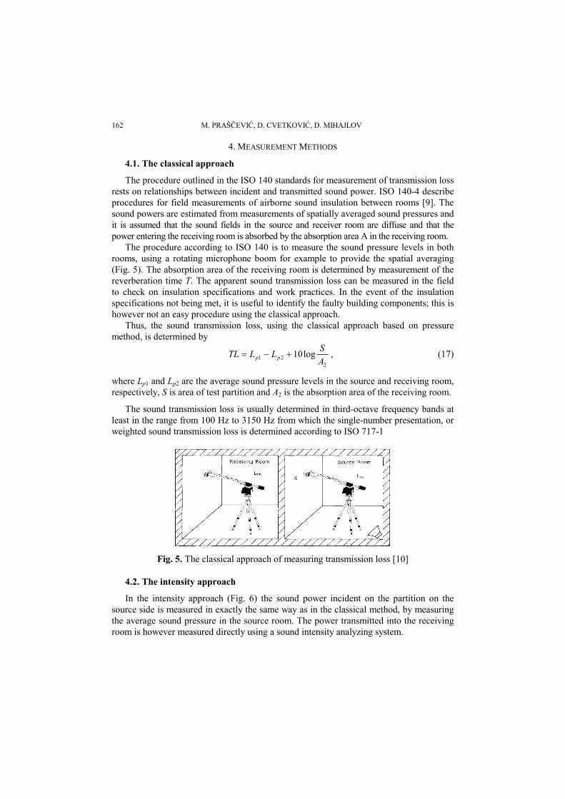
The procedure according to ISO 140 is to measure the sound pressure levels in both rooms, using a rotating microphone boom for example to provide the spatial averaging (Fig. 5). The absorption area of the receiving room is determined by measurement of the reverberation time T. The apparent sound transmission loss can be measured in the field to check on insulation specifications and work practices. In the event of the insulation specifications not being met, it is useful to identify the faulty building components; this is however not an easy procedure using the classical approach.
Thus, the sound transmission loss, using the classical approach based on pressure method, is determined by
2
21 log10A
SLLTL pp , (17)
where Lp1 and Lp2 are the average sound pressure levels in the source and receiving room, respectively, S is area of test partition and A2 is the absorption area of the receiving room.
The sound transmission loss is usually determined in third-octave frequency bands at least in the range from 100 Hz to 3150 Hz from which the single-number presentation, or weighted sound transmission loss is determined according to ISO 717-1
Fig. 5. The classical approach of measuring transmission loss [10]
4.2. The intensity approach
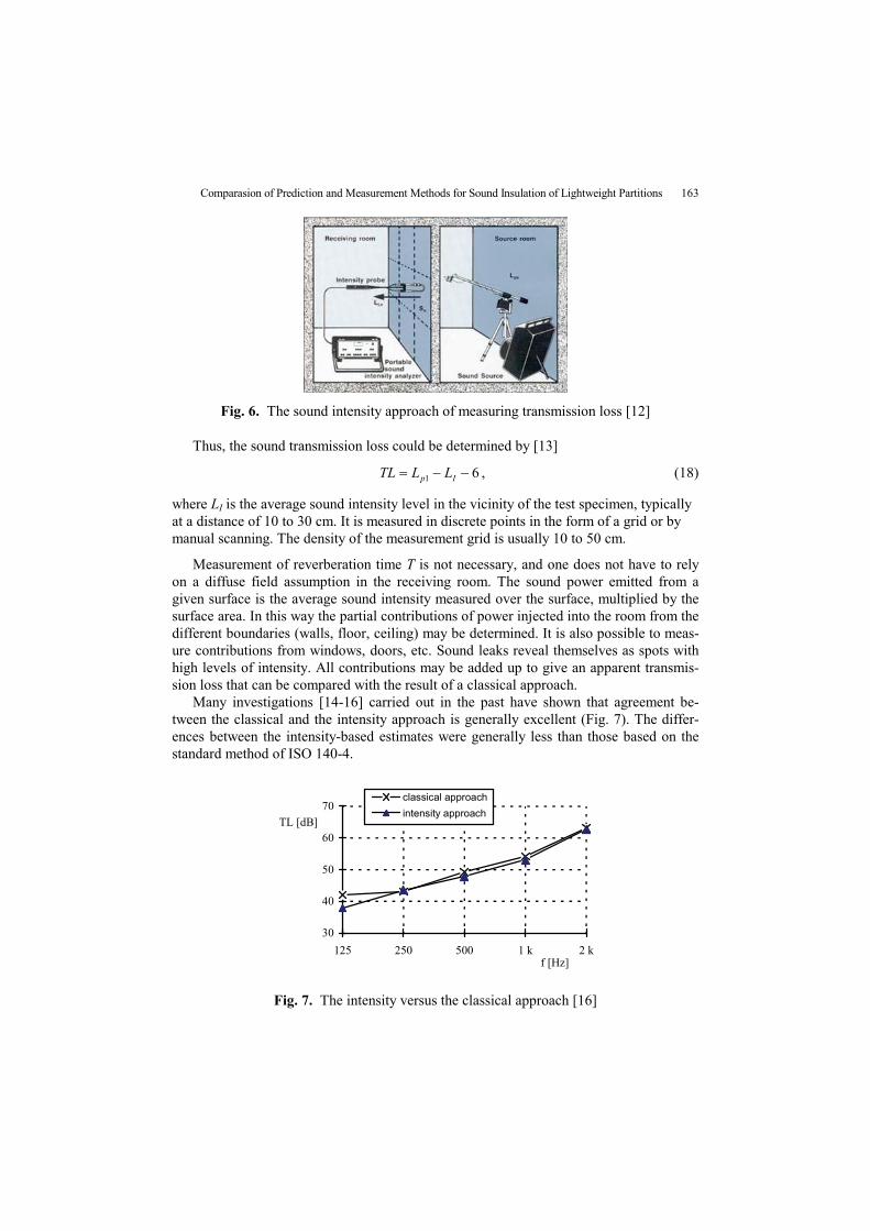
In the intensity approach (Fig. 6) the sound power incident on the partition on the source side is measured in exactly the same way as in the classical method, by measuring the average sound pressure in the source room. The power transmitted into the receiving room is however measured directly using a sound intensity analyzing system.
Comparasion of Prediction and Measurement Methods for Sound Insulation of Lightweight Partitions 163
Fig. 6. The sound intensity approach of measuring transmission loss [12]
Thus, the sound transmission loss could be determined by [13]
61 Ip LLTL , (18)
where LI is the average sound intensity level in the vicinity of the test specimen, typically at a distance of 10 to 30 cm. It is measured in discrete points in the form of a grid or by manual scanning. The density of the measurement grid is usually 10 to 50 cm.
Measurement of reverberation time T is not necessary, and one does not have to rely on a diffuse field assumption in the receiving room. The sound power emitted from a given surface is the average sound intensity measured over the surface, multiplied by the surface area. In this way the partial contributions of power injected into the room from the different boundaries (walls, floor, ceiling) may be determined. It is also possible to meas-ure contributions from windows, doors, etc. Sound leaks reveal themselves as spots with high levels of intensity. All contributions may be added up to give an apparent transmis-sion loss that can be compared with the result of a classical approach.
Many investigations [14-16] carried out in the past have shown that agreement be-tween the classical and the intensity approach is generally excellent (Fig. 7). The differ-ences between the intensity-based estimates were generally less than those based on the standard method of ISO 140-4.
30
40
50
60
70
125 250 500 1 k 2 kf [Hz]
TL [dB]
classical approach
intensity approach
Fig. 7. The intensity versus the classical approach [16]
M. PRAŠČEVIĆ, D. CVETKOVIĆ, D. MIHAJLOV 164
5. COMPARISON OF RESULTS
Single homogeneous panels are examined first, with mass, stiffness, damping and panel size found to be adequate to describe most common building constructions. Double panels are then examined, with additional factors of airgap between the panels, connec-tions between the panels and acoustic absorption in the cavity enabling good engineering predictions of sound transmission loss.
The sound transmission loss of examined panels has been predicted by the described predicted scheme in this paper, in chapter 3. The sound intensity method has been applied for in-situ determination of the sound transmission loss. The experimental procedure has been realized by the measurement chain that is made of the following measurement equipment: Sound Source Type 4224 B&K Building Acoustic Analyzer Type 4418 B&K Dual Channel Real Time Analyzer Type 2144 B&K Sound Intensity Probe Type 3519 B&K
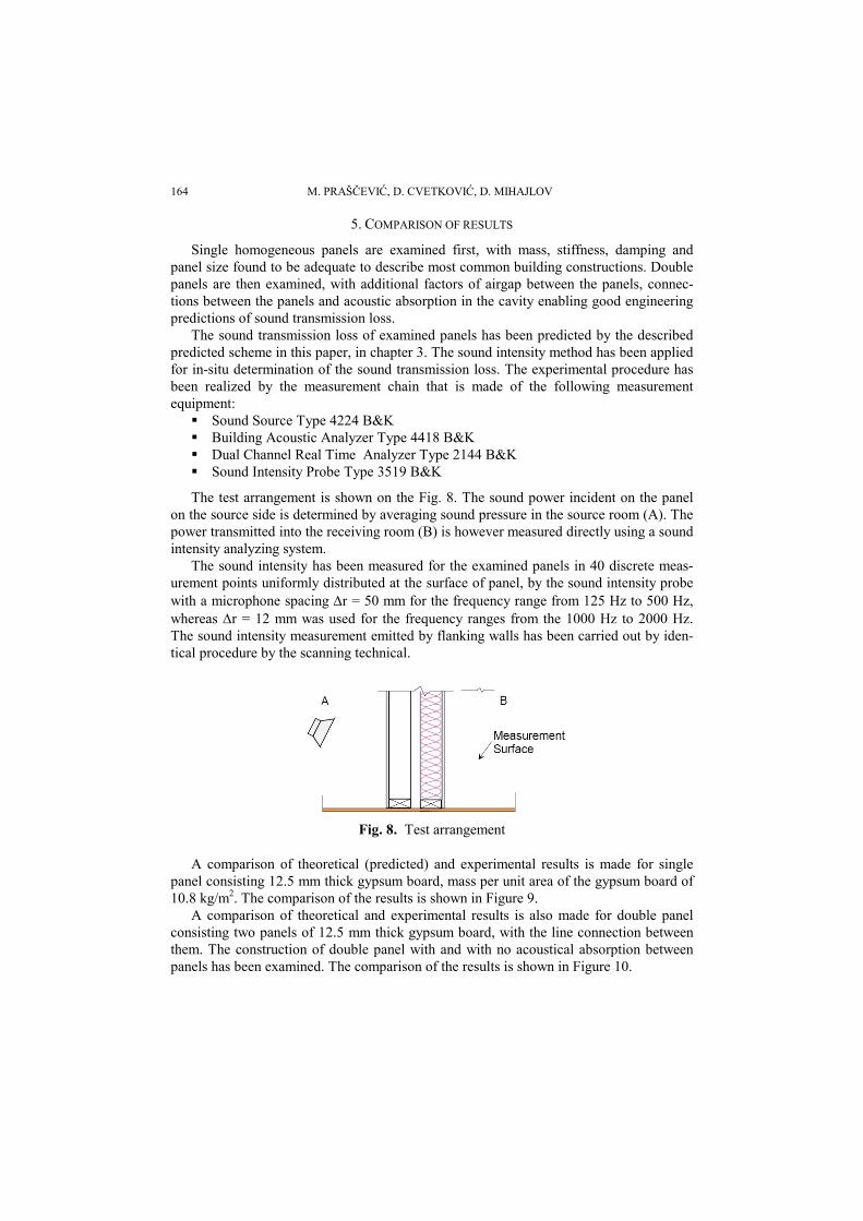
The test arrangement is shown on the Fig. 8. The sound power incident on the panel on the source side is determined by averaging sound pressure in the source room (A). The power transmitted into the receiving room (B) is however measured directly using a sound intensity analyzing system.
The sound intensity has been measured for the examined panels in 40 discrete meas-urement points uniformly distributed at the surface of panel, by the sound intensity probe with a microphone spacing r = 50 mm for the frequency range from 125 Hz to 500 Hz, whereas r = 12 mm was used for the frequency ranges from the 1000 Hz to 2000 Hz. The sound intensity measurement emitted by flanking walls has been carried out by iden-tical procedure by the scanning technical.
Fig. 8. Test arrangement
A comparison of theoretical (predicted) and experimental results is made for single panel consisting 12.5 mm thick gypsum board, mass per unit area of the gypsum board of 10.8 kg/m2. The comparison of the results is shown in Figure 9.
A comparison of theoretical and experimental results is also made for double panel consisting two panels of 12.5 mm thick gypsum board, with the line connection between them. The construction of double panel with and with no acoustical absorption between panels has been examined. The comparison of the results is shown in Figure 10.

Comparasion of Prediction and Measurement Methods for Sound Insulation of Lightweight Partitions 165
0
5
10
15
20
25
30
35
40
50 80 125
200
315
500
800
1250
2000
3150
5000
f [Hz]
TL
[d
B]
Sharp [3], finite panel
Sharp [3], infinite panel
experiment
Kurtovic [7]
Fig. 9. Comparison of the results for single panel
0
10
20
30
40
50
60
50 80 125
200
315
500
800
1250
2000
3150
5000
f [Hz]
TL
[d
B]
Sharp [3], finite panel
Sharp [3], infinite panel
experiment
Kurtovic [8]
0
10
20
30
40
50
60
70
50 80 125
200
315
500
800
1250
2000
3150
5000
f [Hz]
TL
[d
B]
Sharp [3], finite panel
Sharp [3], infinite panel
experiment
Kurtovic [8]
Fig. 10. Comparison of the results for double panel without acoustic absorption in the cavity (upper graph) and with acoustic absorption in the cavity (lower graph)
M. PRAŠČEVIĆ, D. CVETKOVIĆ, D. MIHAJLOV 166
5. CONCLUSIONS
The experimental results show that the predictive schemes of theoretical Sharp' and Kurtovic' models described in this paper are close to the experimental results for exam-ined simple and double panels. It can be seen that the agreement between theory and measurement is excellent for most engineering purposes except when the area of the pan-els is very small and the frequencies are very low.
At low frequencies, the experimental results appear to be significantly affected by the resonance effects associated with the creation of stationary waves within the acoustic cavities especially if the effect of the radiation efficiency of a finite panel is not taken into account then the agreement at low frequencies is not so good.
The size of the panel was found experimentally to be an important variable for the definition of the dips associated with the coincidence effect.
The sound insulation of typical lightweight building constructions can be predicted with acceptable engineering accuracy over the frequency range 50 Hz to 5000 Hz using simple and readily available expressions given in this paper.
REFERENCES
1. F. Fahy, Foundation of Engineering Acoustics, Academic Press, San Diego 2003. 2. V. Hongisto, “Airborne sound insulation of wall structures - measurement and prediction methods”,
doctoral dissertation, Helsinki University of Technology, Helsinki, 2000. 3. D. A Bies , C. H. Hansen, Engineering Noise Control, Spon Press, London, 2003. 4. A. J. B- Tadeu, D. M. R. Mateus, “Sound transmission through single, double and triple glazing.
Experimental evaluation”, Applied Acoustics, Vol. 62, pp. 307-325, 2001. 5. L. L. Beranek, Noise and Vibration Control, McGraw-Hill Book Company, New York, 1971. 6. K. O. Balagh, “Accuracy of the prediction methods for sound transmission loss", Proc. of Inter-noise
2004, Prague, 2004. 7. H. Kurtović, D. Šumarac, “Some difficulties in the calculation of the sound reduction factor of light
panels", Proc. of XLIV ETRAN Conference, pp. 349-352 (in Serbian), Sokobanja, 2000. 8. H. Kurtovic, “Calculation of the sound reduction factor of light double walls", Proc. of XLVII ETRAN
Conference, pp. 456-459, (in Serbian), Herceg Novi, 2003. 9. ISO 140-4, Acoustics – Measurement of sound insulation in buildings and of building elements – Part 4:
Field measurements of airborne sound insulation between rooms, 1998 10. T. G. Nielsen, “Intensity Measurements in Building Acoustics”, Bruel&Kjaer Appliacation Note, BO
0147-11, Denmark, 1986. 11. ISO 717-1, Acoustics – Rating of sound insulation in buildings and of building elements – Part 1:
Airborne sound insulation, 1996. 12. Sound Intensity, Bruel&Kjaer booklet, BR 0476-14, Denmark, 1993. 13. F. J. Fahy, Sound Intensity, 2nd ed., E&FN Spon, London, 1995. 14. H. G. Jonasson, “Sound intensity and sound reduction index”, Applied Acoustics, Vol 40, pp. 281-93, 1993. 15. H. Olsem, M. J. Newman, “Determination of sound reduction indices using intensity techniques in sity”,
Report No. STF40 A92405, Acoustic Research Center, Norwaz, 1992 16. D. Cvetković, M. Praščević, "Sound Insulation as Function Sound Intensity", Journal de Physique IV,
pp. 155-159, France, 1994.

Comparasion of Prediction and Measurement Methods for Sound Insulation of Lightweight Partitions 167
KOMPARATIVNA ANALIZA METODA ZA PRORAČUN I MERENJE ZVUČNE IZOLACIJE LAKIH PREGRADA
Momir Praščević, Dragan Cvetković, Darko Mihajlov
U cilju komparacije različitih konstrukcija, izračunavanja akustičkog komfora u stambenim objektima ili nivoa buke koji potiču od spoljašnih izvora buke kao što je drumski saobraćaj i nalaženja inženjerski optimalnog rešenja za probleme buke važno je poznavanje izolacionih karakteristika pregradnih konstrukcija. Koriščenje lakih pregrada kao pregradnih zidova između stanova postalo je uobičajeno jer se zahtevi za zvučnu izolaciju mogu postići sa manjom površinskom masom pregrade. Međutim, potrebno je veće umeće pri projektovanju i izvođenju pregrada s obzirom da su ti procesi složeniji. Takođe je teže izračunati i izmeriti transmisione gubitke lakih pregrada. Postoje različite metode za izračunavanje i merenje zvučne izolacije pregrada a neke od njih će biti prikazane u ovom adu. Takođe, u radu će biti prikazano poređenje eksperimentalnih rezultata zvučne izolacije lakih pregrada sa rezultatima dobijenim korišćenjem različitih teorijskih modela na primeru jednostrukih homogenih pregrada i dvostukih pregrada sa i bez ispune između obloga pregrade.
Ključne reči: zvučna izolacija, lake pregrade, prenosni gubici.