CompactLogix ControlNet Interface Module Installation ... AC... · CompactLogix ControlNet...
36
Publication 1768-IN006A-EN-P - September 2007 Installation Instructions CompactLogix ControlNet Interface Module Catalog Numbers 1768-CNB, 1768-CNBR About This Publication Use this document as a guide to install the CompactLogix ControlNet Bridge Interface Module. Topic Page Important User Information 2 North American Hazardous Location Approval 3 Environment and Enclosure 4 Prevent Electrostatic Discharge 5 Before You Begin 6 Installing the Modules 8 Connect to a ControlNet Network 16 Remove a Module 22 Interpreting the Status Indicators 24 ControlNet Network Channel-status Indicators 27 Specifications 28
Transcript of CompactLogix ControlNet Interface Module Installation ... AC... · CompactLogix ControlNet...
Installation Instructions
CompactLogix ControlNet Interface Module
Catalog Numbers 1768-CNB, 1768-CNBR
About This PublicationUse this document as a guide to install the CompactLogix ControlNet Bridge Interface Module.
Topic Page
Important User Information 2
North American Hazardous Location Approval 3
Environment and Enclosure 4
Prevent Electrostatic Discharge 5
Before You Begin 6
Installing the Modules 8
Connect to a ControlNet Network 16
Remove a Module 22
Interpreting the Status Indicators 24
ControlNet Network Channel-status Indicators 27
Specifications 28
Publication 1768-IN006A-EN-P - September 2007

2 CompactLogix ControlNet Interface Module
Important User Information
Solid state equipment has operational characteristics differing from those of electromechanical equipment. Safety Guidelines for the Application, Installation and Maintenance of Solid State Controls (publication SGI-1.1 available from your local Rockwell Automation sales office or online at http://literature.rockwellautomation.com) describes some important differences between solid state equipment and hard-wired electromechanical devices. Because of this difference, and also because of the wide variety of uses for solid state equipment, all persons responsible for applying this equipment must satisfy themselves that each intended application of this equipment is acceptable.In no event will Rockwell Automation, Inc. be responsible or liable for indirect or consequential damages resulting from the use or application of this equipment.The examples and diagrams in this manual are included solely for illustrative purposes. Because of the many variables and requirements associated with any particular installation, Rockwell Automation, Inc. cannot assume responsibility or liability for actual use based on the examples and diagrams.No patent liability is assumed by Rockwell Automation, Inc. with respect to use of information, circuits, equipment, or software described in this manual.Reproduction of the contents of this manual, in whole or in part, without written permission of Rockwell Automation, Inc., is prohibited.Throughout this manual, when necessary, we use notes to make you aware of safety considerations.
WARNING Identifies information about practices or circumstances that can cause an explosion in a hazardous environment, which may lead to personal injury or death, property damage, or economic loss.
IMPORTANT Identifies information that is critical for successful application and understanding of the product.
ATTENTION Identifies information about practices or circumstances that can lead to personal injury or death, property damage, or economic loss. Attentions help you to identify a hazard, avoid a hazard and recognize the consequences.
SHOCK HAZARD
Labels may be on or inside the equipment, for example, a drive or motor, to alert people that dangerous voltage may be present.
BURN HAZARD
Labels may be on or inside the equipment, for example, a drive or motor, to alert people that surfaces may reach dangerous temperatures.
Publication 1768-IN006A-EN-P - September 2007

CompactLogix ControlNet Interface Module 3
North American Hazardous Location Approval
The following information applies when operating this equipment in hazardous locations.
Informations sur l'utilisation de cet équipement en environnements dangereux.
Products marked CL I, “DIV 2, GP A, B, C, D” are suitable for use in Class I Division 2 Groups A, B, C, D, Hazardous Locations and nonhazardous locations only. Each product is supplied with markings on the rating nameplate indicating the hazardous location temperature code. When combining products within a system, the most adverse temperature code (lowest “T” number) may be used to help determine the overall temperature code of the system. Combinations of equipment in your system are subject to investigation by the local Authority Having Jurisdiction at the time of installation.
Les produits marqués CL I, “DIV 2, GP A, B, C, D” ne conviennent qu'à une utilisation en environnements de Classe I Division 2 Groupes A, B, C, D dangereux et non dangereux. Chaque produit est livré avec des marquages sur sa plaque d'identification qui indiquent le code de température pour les environnements dangereux. Lorsque plusieurs produits sont combinés dans un système, le code de température le plus défavorable (code de température le plus faible) peut être utilisé pour déterminer le code de température global du système. Les combinaisons d'équipements dans le système sont sujettes à inspection par les autorités locales qualifiées au moment de l'installation.
EXPLOSION HAZARD
Do not disconnect equipment unless power has been removed or the area is known to be nonhazardous.Do not disconnect connections to this equipment unless power has been removed or the area is known to be nonhazardous. Secure any external connections that mate to this equipment by using screws, sliding latches, threaded connectors, or other means provided with this product.Substitution of components may impair suitability for Class I, Division 2.If this product contains batteries, they must only be changed in an area known to be nonhazardous.
RISQUE D'EXPLOSION
Couper le courant ou s'assurer que l'environnement est classé non dangereux avant de débrancher l'équipement.Couper le courant ou s'assurer que l'environnement est classé non dangereux avant de débrancher les connecteurs. Fixer tous les connecteurs externes reliés à cet équipement à l'aide de vis, loquets coulissants, connecteurs filetés ou autres moyens fournis avec ce produit.La substitution de composants peut rendre cet équipement inadapté à une utilisation en environnement de Classe I, Division 2.S'assurer que l'environnement est classé non dangereux avant de changer les piles.
WARNING AVERTISSEMENT
Publication 1768-IN006A-EN-P - September 2007

4 CompactLogix ControlNet Interface Module
Environment and Enclosure
ATTENTION This equipment is intended for use in a Pollution Degree 2 industrial environment, in overvoltage Category II applications (as defined in IEC publication 60664-1), at altitudes up to 2000 m (6561 ft) without derating.
This equipment is considered Group 1, Class A industrial equipment according to IEC/CISPR Publication 11. Without appropriate precautions, there may be potential difficulties ensuring electromagnetic compatibility in other environments due to conducted as well as radiated disturbance.
This equipment is supplied as open-type equipment. It must be mounted within an enclosure that is suitably designed for those specific environmental conditions that will be present and appropriately designed to prevent personal injury resulting from accessibility to live parts. The enclosure must have suitable flame-retardant properties to prevent or minimize the spread of flame, complying with a flame spread rating of 5VA, V2, V1, V0 (or equivalent) if non-metallic. The interior of the enclosure must be accessible only by the use of a tool. Subsequent sections of this publication may contain additional information regarding specific enclosure type ratings that are required to comply with certain product safety certifications.
In addition to this publication, see:
• Industrial Automation Wiring and Grounding Guidelines, for additional installation requirements, Allen-Bradley publication 1770-4.1.
• NEMA Standards publication 250 and IEC publication 60529, as applicable, for explanations of the degrees of protection provided by different types of enclosure.
Publication 1768-IN006A-EN-P - September 2007

CompactLogix ControlNet Interface Module 5
Prevent Electrostatic Discharge
For additional information, refer to Industrial Automation Wiring and Grounding Guidelines, publication 1770-4.1.
ATTENTION This equipment is sensitive to electrostatic discharge, which can cause internal damage and affect normal operation. Follow these guidelines when you handle this equipment:
• Touch a grounded object to discharge potential static.• Wear an approved grounding wriststrap.• Do not touch connectors or pins on component boards.• Do not touch circuit components inside the equipment.• Use a static-safe workstation, if available.• Store the equipment in appropriate static-safe packaging when
not in use.
Publication 1768-IN006A-EN-P - September 2007
6 CompactLogix ControlNet Interface Module
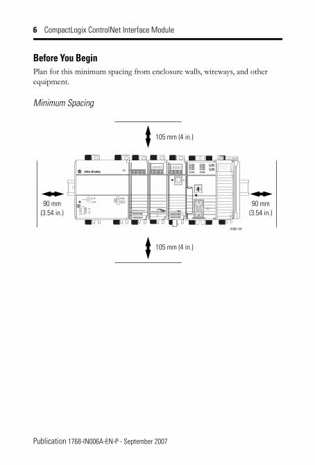
Before You BeginPlan for this minimum spacing from enclosure walls, wireways, and other equipment.
Minimum Spacing
31661-M
PowerOU T
24Vdc NO
MIN
AL
120W90 mm(3.54 in.)
105 mm (4 in.)
90 mm(3.54 in.)
105 mm (4 in.)
Publication 1768-IN006A-EN-P - September 2007

CompactLogix ControlNet Interface Module 7
Required System Components
Item Catalog Number or Size
1768 CompactLogix power supply 1768-PA3
1768 CompactLogix controller 1768-L4x
1769 end capConnects to the controller as either the last module:
• without any 1769 series modules attached to the controller (1768 series only).
• with a combination of 1768 series and 1769 series modules attached to the controller.
1769-ECR
Serial cable to connect to a 1768 controller 1756-CP3
BNC connectors See Connect to a ControlNet Network.
DIN rail or mounting screws DIN rail Either of these sizes:
• 35 x 7.5 mm (EN 50 022 - 35 x 7.5)
• 35 x 15 mm (EN 50 022 - 35 x 15)
Screws M4 or #8 panhead screws
Publication 1768-IN006A-EN-P - September 2007

8 CompactLogix ControlNet Interface Module
Installing the Modules
Mount Modules with Screws
The steps in these instructions show how to mount the modules on DIN rail. If you are using screws instead of DIN rail, make these changes to the instructions.
1. Follow the steps in Mount the Module on the DIN Rail on page 10 to connect the modules together.
2. Use the modules as a template and mark pilot holes on your panel.
3. Drill the pilot holes for M4 or #8 screws.
ATTENTION This product is grounded through the DIN rail to chassis ground. Use zinc-plated yellow-chromate steel DIN rail to assure proper grounding. The use of other DIN rail materials (for example, aluminum or plastic) that can corrode, oxidize, or are poor conductors, can result in improper or intermittent grounding. Secure DIN rail to mounting surface approximately every 200 mm (7.87 in.) and use end-anchors appropriately.
IMPORTANT Do not use screws and DIN rail to mount the modules. It is possible to break the mounting tabs off if you screw the modules to the panel while they are on DIN rail.
ATTENTIONDo not let metal to fall into modules while drilling. This could damage the modules.
Publication 1768-IN006A-EN-P - September 2007

CompactLogix ControlNet Interface Module 9
4. Use M4 or #8 screws to mount the modules to your panel with 1.16 Nm (10 lb-in) of torque.
5. Ground the module on a ground bus with a dedicated Earth-ground stake.
6. Connect the ground bus to a functional Earth-ground on the DIN rail or panel.
Refer to Industrial Automation Wiring and Grounding Guidelines, publication 1770-4.1, for additional information.
Install the DIN Rail
Mount the DIN rail in a suitable location.
Publication 1768-IN006A-EN-P - September 2007

10 CompactLogix ControlNet Interface Module
Mount the Module on the DIN Rail
TIP Throughout this installation instruction the graphic used for the module is the 1768-CNBR module.
(front)
(rear)
1
1768-CNB Module 1768-CNBR Module
31646A-M 31646AB-M
a
b
31647 -M
(front)
(rear)
2
c
Publication 1768-IN006A-EN-P - September 2007

CompactLogix ControlNet Interface Module 11
a
b
31647 -M
(front)
(rear)
2
c
Publication 1768-IN006A-EN-P - September 2007
12 CompactLogix ControlNet Interface Module
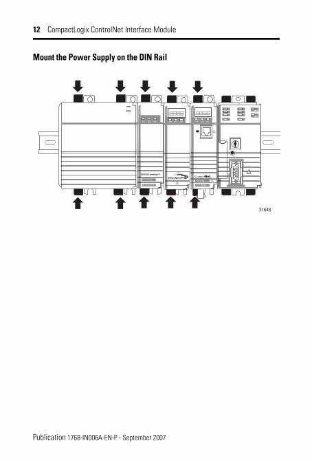
Mount the Power Supply on the DIN Rail
Publication 1768-IN006A-EN-P - September 2007

CompactLogix ControlNet Interface Module 13
Mount the I/O Modules on the DIN Rail
1
31649-M
a
b d
c
a
b
c
31650-M
2
Publication 1768-IN006A-EN-P - September 2007
14 CompactLogix ControlNet Interface Module
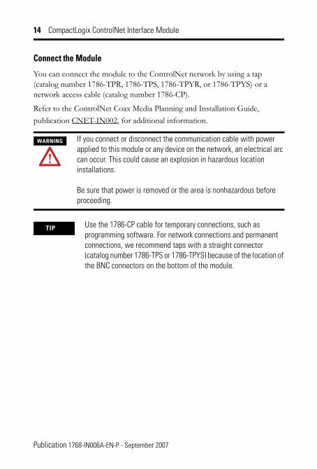
Connect the Module
You can connect the module to the ControlNet network by using a tap (catalog number 1786-TPR, 1786-TPS, 1786-TPYR, or 1786-TPYS) or a network access cable (catalog number 1786-CP).
Refer to the ControlNet Coax Media Planning and Installation Guide, publication CNET-IN002, for additional information.
WARNING If you connect or disconnect the communication cable with power applied to this module or any device on the network, an electrical arc can occur. This could cause an explosion in hazardous location installations.
Be sure that power is removed or the area is nonhazardous before proceeding.
TIP Use the 1786-CP cable for temporary connections, such as programming software. For network connections and permanent connections, we recommend taps with a straight connector (catalog number 1786-TPS or 1786-TPYS) because of the location of the BNC connectors on the bottom of the module.
Publication 1768-IN006A-EN-P - September 2007

CompactLogix ControlNet Interface Module 15
Set the Network Address Switches
Use a small screwdriver to set the module�s network address switches. You must specify a unique ControlNet network address. You can select an address of 01�99.Network Address Switches
05 06
6
8
7
07
90
43
21
5
0809
0001
02
0304
NETWORK
ADDRESS
31651- M
05 06
6
8
7
07
90
43
21
5
0809
0001
02
0304
NETWORK
ADDRESSSide of Module
Fron
t of M
odul
e
This module’s networkaddress is 99.
Publication 1768-IN006A-EN-P - September 2007

16 CompactLogix ControlNet Interface Module
Connect to a ControlNet Network
The 1768-CNB and 1768-CNBR modules have a network access port (NAP) available. The most common and easiest way to connect to the network is by using the a ControlNet tap. Perform the following steps to connect the module to the network by using a tap.
1. Remove and save the dust caps from the ControlNet network taps.
2. Connect the tap�s straight or right-angle connector to the module�s BNC connector.
ATTENTION Do not allow any metal portions of the tap to contact any conductive material. If you disconnect the tap from the module, place the dust cap back on the straight or right-angle connector to prevent the connector from accidentally contacting a metallic grounded surface.
If your node supports Connect the tap’s connector
Nonredundant media 1768-CNB module
To the channel A connector on the module (channel B on the 1768-CNBR module is not used)(1)
(1) While both channels are active, we recommend using channel A for non-redundant media.
Redundant media • From trunkline A to channel A on the 1768-CNBR module
• From trunkline B to channel B on the 1768-CNBR module
Dust Cap
Segment 1 Segment 2
Dust Cap
1768-CNBR Segments 1 and 2
1768-CNB Segment 1
Publication 1768-IN006A-EN-P - September 2007

CompactLogix ControlNet Interface Module 17
IMPORTANT On 1768-CNBR installations, make sure the correct network is connected to the correct tap connection. Reversing the tap connections will result in incorrect status display.
When you are using redundant media, connect the channel of each partner to the same network segment.
Segment 2
Tap Tap
05 06
6
8
7
07
90
43
21
5
0809
0001
02
0304
NETWORK
ADDRESS
31653- M
A B
05 06
6
8
7
07
90
43
21
5
0809
0001
02
0304
NETWORK
ADDRESS
A
Segment 1
Tap
Publication 1768-IN006A-EN-P - September 2007
18 CompactLogix ControlNet Interface Module
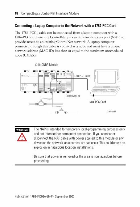
Connecting a Laptop Computer to the Network with a 1784-PCC Card
The 1784-PCC1 cable can be connected from a laptop computer with a 1784-PCC card into any ControlNet product�s network access port (NAP) to provide access to an existing ControlNet network. A laptop computer connected through this cable is counted as a node and must have a unique network address (MAC ID) less than or equal to the maximum unscheduled node (UMAX).
WARNING The NAP is intended for temporary local-programming purposes only and not intended for permanent connection. If you connect or disconnect the NAP cable with power applied to this module or any device on the network, an electrical arc can occur. This could cause an explosion in hazardous location installations.
Be sure that power is removed or the area is nonhazardous before proceeding.
31654a-M
1784-PCC1 Cable
ControlNet Link
1784-PCC Card
1768-CNBR Module
Publication 1768-IN006A-EN-P - September 2007
CompactLogix ControlNet Interface Module 19
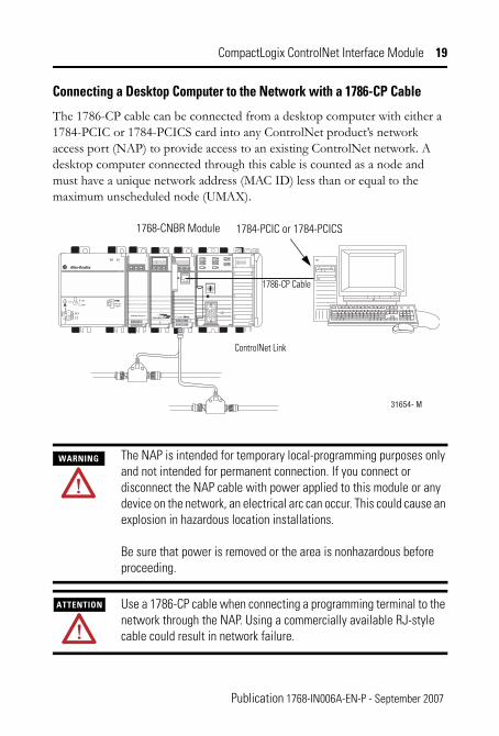
Connecting a Desktop Computer to the Network with a 1786-CP Cable
The 1786-CP cable can be connected from a desktop computer with either a 1784-PCIC or 1784-PCICS card into any ControlNet product�s network access port (NAP) to provide access to an existing ControlNet network. A desktop computer connected through this cable is counted as a node and must have a unique network address (MAC ID) less than or equal to the maximum unscheduled node (UMAX).
WARNING The NAP is intended for temporary local-programming purposes only and not intended for permanent connection. If you connect or disconnect the NAP cable with power applied to this module or any device on the network, an electrical arc can occur. This could cause an explosion in hazardous location installations.
Be sure that power is removed or the area is nonhazardous before proceeding.
ATTENTION Use a 1786-CP cable when connecting a programming terminal to the network through the NAP. Using a commercially available RJ-style cable could result in network failure.
31654- M
1786-CP Cable
ControlNet Link
1784-PCIC or 1784-PCICS1768-CNBR Module
Publication 1768-IN006A-EN-P - September 2007

20 CompactLogix ControlNet Interface Module
Connecting a Desktop Computer Directly to the ControlNet Network
A 1786-TPR, 1786-TPS, 1786-TPYR, or 1786-TPYS cable can be connected from a desktop computer with either a 1784-PCIC or 1784-PCICS card directly to an existing ControlNet network. A desktop computer connected through this cable is counted as a node and must have a unique network address (MAC ID) less than or equal to the maximum unscheduled node (UMAX).
When connecting the module to a ControlNet network, you should also refer to the following documentation:
• ControlNet Coax Taps Installation Instructions, publication 1786-IN007
• ControlNet Coax Media System Planning and Installation Manual, publication CNET-IN002
TIP For network connections, we recommend taps with a straight connector (catalog number 1786-TPS or 1786-TPYS) because of the location of the BNC connectors on the bottom of the module.
ATTENTION If a SoftLogix5800 processor is running on the computer containing the 1784-PCIC or 1784-PCICS card, do not use the 1786-CP cable to connect the card to the ControlNet network. Instead, connect the card directly to the ControlNet network.
Publication 1768-IN006A-EN-P - September 2007

CompactLogix ControlNet Interface Module 21
Confirm Installation
The three bicolor (red/green) status indicators on the module provide diagnostic information about the module and its connections to the network.
See Interpreting the Status Indicators on page 24 if the lights are in other states.
31598-G
P o we rO U T
L 1
L 2 /N
Solid Green Solid Green
Solid or Flashing Green
31657-M
Module Status Display - See page 24.
ControlNet Channel Status Indicators - See Page 27.
Channel A BNC ConnectorChannel B BNC Connector
1768-CNB and 1768-CNBR Modules
Publication 1768-IN006A-EN-P - September 2007

22 CompactLogix ControlNet Interface Module
Remove a Module
To remove or slide a module, the DIN rail connectors on the module to its left must be pulled out.
31658-M
P o we rO UT
a
b d fc - Off
e
24
Vd
c N
OM
INA
L
12
0W
1
31659-M
PowerOU T
ac
b
24Vdc NO
MIN
AL
120W
2
Publication 1768-IN006A-EN-P - September 2007

CompactLogix ControlNet Interface Module 23
Wait for the Lights to Turn Off Before Removing a Module
After you turn off the power, wait for all of the lights on the power supply and controller to turn off before you disconnect any modules.
• When you turn off the power, the controller writes its program to memory.
• If you don�t wait for the lights to turn off, you will lose your program.
IMPORTANT When you turn the CompactLogix power supply off, make sure you wait for all status indicators on the power supply and controller to turn off before disconnecting any part from the system.
If you disconnect the CompactLogix system while the controller is still writing its program to memory, the program write will not be completed and you will lose your program.
Publication 1768-IN006A-EN-P - September 2007

24 CompactLogix ControlNet Interface Module
Interpreting the Status IndicatorsModule Status Display Descriptions
Status Display
Cause Action
Off None The module is not communicating due to a power supply fault or internal fault.
1. Check the power supply.2. Check the cable connectors.3. Make sure the module is firmly
seated in the chassis.4. Replace the module if the indicator
remains off.Red Msg
scrollsThe module’s network address is set to 00, an invalid ControlNet network address.
If switches are set to 00 the display scrolls: FAULT: ADDRESS SWITCHES = 00, ILLEGAL.
1. Turn chassis power supply off.2. Remove the module from the
chassis.3. Set the network address switches
to a unique address, 01…99.4. Install the module in the chassis.5. Turn chassis power supply on if it's
off.
BPA# ERR
The module detected a different slot address from that latched in when you cycled power. Excessive noise on the backplane causes this error.
Replace the chassis or module.
BPRX ERR
There are too many CRC errors being generated by the multicast backplane receiver, so the backplane multicast receivers have been shut off.
Replace the module.
BPIC ERR
There is a hardware fault within the module.
Replace the module.
CNIC ERR
OK
Publication 1768-IN006A-EN-P - September 2007

CompactLogix ControlNet Interface Module 25
Red DUPL NODE
The module’s network address is the same as another module’s on the link.
1. Turn chassis power supply off.2. Remove the module from the
chassis.3. Set the network address switches
to a unique address, 01…99.4. Install the module in the chassis.5. Turn chassis power supply on if it's
off.RACK ERR
Cannot read backplane EEPROM, or rack/slot address incorrect.
Replace the chassis.
Flashing red
BOOT The module has invalid firmware.
Update module firmware with ControlFlash Update Utility.
ROM
UPDT
Flash update is in progress. None required.
SNGL KPR!
The module detected that it has been connected to a ControlNet 1.5 (single-keeper) network.
Update the module’s firmware at MAC ID 01 and reschedule the network.
Green OK Normal operation. None required.INIT The module is initializing.BW >MAX
The module is receiving too much network traffic and connections are timing out. The network bandwidth has been exceeded.
None (temporary condition).
If this happens frequently, add another 1768-CNB or 1768-CNBR module and split the traffic between them.
Module Status Display Descriptions
Status Display
Cause ActionOK
Publication 1768-IN006A-EN-P - September 2007

26 CompactLogix ControlNet Interface Module
Green SW ERR
The node address switch changed after cycling power.
None required, but we recommend that you either return switches to their original settings or replace the module, since this could indicate a hardware problem.
Flashing green
CNFG ERR
ControlNet network configuration error.
Recheck configuration.
NET ERR
Network cabling error or no other active nodes on the network.
Recheck your network cabling and make sure another node on the network is active (online).
Module Status Display Descriptions
Status Display
Cause ActionOK
Publication 1768-IN006A-EN-P - September 2007

CompactLogix ControlNet Interface Module 27
ControlNet Network Channel-status IndicatorsThe ControlNet network channel-status indicators appear in one of the following states:
• Steady - indicator is on continuously in the defined state.• Alternating - the two indicators alternate between the two defined
states at the same time (applies to both indicators viewed together). The two indicators are always in opposite states, out of phase.
• Flashing - the indicator alternates between the two defined states (applies to each indicator viewed independent of the other). If both indicators are flashing, they must flash together, in phase.
The ControlNet Network Channel Status Indicators table summarizes the meanings of these states.
ControlNet Network Channel-status Indicators
Cause Action
Off No power None or apply power.Steady red Faulted unit Cycle power or reset unit.
If fault persists, contact Allen-Bradley representative or distributor.
Alternating red/green
Self-test None.
Alternating red/off Incorrect node configuration Check network address and other ControlNet network configuration parameters.
Off Channel disabled Program network for redundant media, if required.
Steady green Normal operation None.
orA B
Publication 1768-IN006A-EN-P - September 2007

28 CompactLogix ControlNet Interface Module
Publication 1768-IN006A-EN-P - September 2007
Specifications
Flashing green/off Temporary errors None; unit will self-correct.Node is not configured to go on line
Make sure the configuration manager node is present and working and selected address is
not greater than selected UMAX.(1)
Flashing red/off Media fault Check media. For example, broken cables, loose connectors, missing terminators.
No other nodes present on network
Add other nodes to the network.
Flashing red/green Incorrect network configuration Cycle power or reset unit.
If fault persists, contact A-B representative or distributor.
(1) The configuration manager node is the node responsible for distributing ControlNet network configuration data to all nodes on the network.
CompactLogix ControlNet Interface Module - 1768-CNB and 1768-CNBR
Attribute Value
Device type Communication interface
Communication interface type Bridge
Connections supported, max 48
Dimensions (HxWxDx), approx. 132 x 56.7 x 105.1 mm (5.20 x 2.23 x 4.12 in.)
Mounting type Din Rail or Panel Mount
Mounting location 1768 ControlLogix Chassis
ControlNet Network Channel-status Indicators
Cause Actionor
A B

CompactLogix ControlNet Interface Module 29
Din rail mount Either of these sizes:
• 35 x 7.5 mm (EN 50 022 - 35 x 7.5)
• 35 x 15 mm (EN 50 022 - 35 x 15)
Mounting screw torque 1.16 Nm (10 lb-in), using M4 or #8 panhead screws
Weight, approx. 1768-CNB 1768-CNBR
0.260 kg (0.57 lb) 0.293 kg (0.64 lb)
Connectors 1768-CNB 1768-CNBR
1 BNC connector for non-redundant media operation 1 NAP (RJ45 8-pin with shield) 2 BNC connectors for redundant media operation 1 NAP (RJ45 8-pin with shield)
Cable Quad-shield RG-6 coaxial cable
Wiring category(1) 2 - on communication ports
Number of nodes, max 99
Slot width 1, can be connected in any slot 1…4
Backplane current at 5 V 1 A
Power consumption 5.14 W
Power dissipation 5.14 W
Thermal dissipation 17.5 BTU/hr
Isolation (continuous-voltage rating)
30V, Functional Insulation Type Tested at 710V dc for 60 s, ControlNet network to system
North American temp code T4A
ControlNet network communication rate
5 Mbps
Diagnostics Yes
CompactLogix ControlNet Interface Module - 1768-CNB and 1768-CNBR
Attribute Value
Publication 1768-IN006A-EN-P - September 2007
30 CompactLogix ControlNet Interface Module
(1) Use this Conductor Category information for planning conductor routing. Refer to Industrial Automation Wiring and Grounding Guidelines, publication 1770-4.1.
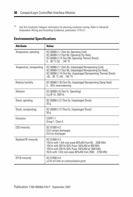
Environmental Specifications
Attribute Value
Temperature, operating IEC 60068-2-1 (Test Ad, Operating Cold), IEC 60068-2-2 (Test Bd, Operating Dry Heat), IEC 60068-2-14 (Test Nb, Operating Thermal Shock): 0…60 °C (32…140 °F)
Temperature, nonoperating IEC 60068-2-1 (Test Ab, Unpackaged Nonoperating Cold), IEC 60068-2-2 (Test Bb, Unpackaged Nonoperating Dry Heat), IEC 60068-2-14 (Test Na, Unpackaged Nonoperating Thermal Shock): -40…85 °C (-40…185 °F)
Relative humidity IEC 60068-2-30 (Test Db, Unpackaged Nonoperating Damp Heat): 5…95% noncondensing
Vibration IEC 60068-2-6 (Test Fc, Operating): 5 g @ 10...500 Hz
Shock, operating IEC 60068-2-27 (Test Ea, Unpackaged Shock): 30 g
Shock, nonoperating IEC 60068-2-27 (Test Ea, Unpackaged Shock): 50 g
Emissions CISPR 11: Group 1, Class A
ESD immunity IEC 61000-4-2: 6 kV contact discharges 8 kV air discharges
Radiated RF immunity IEC 61000-4-3: 10V/m with 1 kHz sine-wave 80%AM from 80…2000 MHz 10V/m with 200 Hz 50% Pulse 100%AM at 900 MHz 10V/m with 200 Hz 50% Pulse 100%AM at 1890 MHz 3V/m with 1 kHz sine-wave 80%AM from 2000…2700 MHz
EFT/B immunity IEC 61000-4-4: ±2 kV at 5 kHz on communication ports
Publication 1768-IN006A-EN-P - September 2007

CompactLogix ControlNet Interface Module 31
Surge transient immunity IEC 61000-4-5: ±2 kV line-earth (CM) on communication ports
Conducted RF immunity IEC 61000-4-6: 10V rms with 1 kHz sine-wave 80%AM from 150 kHz…80 MHz
Enclosure type rating None (open-style)
Certifications
Certification (when product is marked)(1)
Value
c-UL-us UL Listed Industrial Control Equipment, certified for US and Canada. See UL File E65584. UL Listed for Class I, Division 2 Group A,B,C,D Hazardous Locations, certified for U.S. and Canada. See UL File E194810.
CE European Union 2004/108/EC EMC Directive, compliant with: EN 50082-2; Industrial Immunity EN 61326; Meas./Control/Lab., Industrial Requirements EN 61000-6-2; Industrial Immunity EN 61000-6-4; Industrial Emissions EN 61131-2; Programmable Controllers (Clause 8, Zone A & B)
C-Tick Australian Radiocommunications Act, compliant with: AS/NZS CISPR 11; Industrial Emissions
CI ControlNet International conformance tested to ControlNet network specifications
(1) See the Product Certification website: http://www.ab.com Provides declarations of conformity, certificates, and other certification details.
Environmental Specifications
Attribute Value
Publication 1768-IN006A-EN-P - September 2007

32 CompactLogix ControlNet Interface Module
Additional ResourcesThese documents contain additional information concerning related Rockwell Automation products.
Resource Description
Industrial Automation Wiring and Grounding Guidelines, publication 1770-4.1
Provides general guidelines for installing a Rockwell Automation industrial system.
ControlNet Modules in Logix5000 Control Systems, publication CNET-UM001
Describes how you can use ControlNet with your Logix5000 controller to communicate between your controller and various devices on the ControlNet network.
CompactLogix Power Supplies Installation Instructions, publication 1768-IN001
Describes how to install the 1768-PA3 and 1768-PB3 CompactLogix power supplies.
CompactLogix Controller Installation Instructions, publication 1768-IN004
Describes how to install CompactLogix controllers.
CompactLogix Controller User Manual, publication 1768-UM001
Describes the necessary tasks to install, configure, program, and operate a CompactLogix system.
ControlNet Coax Taps Installation Instructions, publication 1786-IN007
Provides the procedures and specifications for the installation of ControlNet coaxial taps.
ControlNet Coax Media Planning and Installation Guide, publication CNET-IN002
Provides the details about how to plan and install ControlNet network coax hardware.
ControlNet Fiber Media Planning and Installation Guide, publication CNET-IN001
Provides the information you need to get started with the ControlNet fiber media system, offers general guidelines for fiber cable installation, and describes how to install and verify your ControlNet fiber media system.
Logix5000 Controllers Common Procedures Reference Manual, publication 1756-PM001
Contains common procedures that are related to all Logix5000 controllers.
Product Certifications website, http://ab.com
Provides declarations of conformity, certificates, and other certification details.
Publication 1768-IN006A-EN-P - September 2007

CompactLogix ControlNet Interface Module 33
Notes:
Publication 1768-IN006A-EN-P - September 2007

34 CompactLogix ControlNet Interface Module
Notes:
Publication 1768-IN006A-EN-P - September 2007

CompactLogix ControlNet Interface Module 35
Notes:
Publication 1768-IN006A-EN-P - September 2007

Publication 1768-IN006A-EN-P - September 2007 PN 953002-95
Rockwell Automation SupportRockwell Automation provides technical information on the Web to assist you in using its products. At http://support.rockwellautomation.com, you can find technical manuals, a knowledge base of FAQs, technical and application notes, sample code and links to software service packs, and a MySupport feature that you can customize to make the best use of these tools.
For an additional level of technical phone support for installation, configuration, and troubleshooting, we offer TechConnect Support programs. For more information, contact your local distributor or Rockwell Automation representative, or visit http://support.rockwellautomation.com.
Installation AssistanceIf you experience a problem with a hardware module within the first 24 hours of installation, please review the information that's contained in this manual. You can also contact a special Customer Support number for initial help in getting your module up and running.
New Product Satisfaction ReturnRockwell tests all of its products to ensure that they are fully operational when shipped from the manufacturing facility. However, if your product is not functioning, it may need to be returned.
United States 1.440.646.3434 Monday – Friday, 8am – 5pm EST
Outside United States Please contact your local Rockwell Automation representative for any technical support issues.
United States Contact your distributor. You must provide a Customer Support case number (see phone number above to obtain one) to your distributor in order to complete the return process.
Outside United States Please contact your local Rockwell Automation representative for return procedure.
Allen-Bradley, Rockwell Automation, RSLinx Classic, RSLinx Enterprise, RSNetWorx for ControlNet, RSNetWorx for DeviceNet, RSNetWorx for EtherNet/IP, CompactLogix, ControlLogix, ControlFlash, TechConnect, and Logix5000 are trademarks of Rockwell Automation, Inc.
Trademarks not belonging to Rockwell Automation are property of their respective companies.
Copyright © 2007 Rockwell Automation, Inc. All rights reserved. Printed in the U.S.A.