Compact Vertical Machining Center - Kent USAlibrary.kentusa.com/Brochures/CNC Machines/Vertical...
17
1 Compact Vertical Machining Center KVR-3618A Technical Catalog www.kentcnc.com
Transcript of Compact Vertical Machining Center - Kent USAlibrary.kentusa.com/Brochures/CNC Machines/Vertical...

1
Compact Vertical Machining CenterKVR-3618A
Technical Catalog
w w w . k e n t c n c . c o m

w w w . k e n t c n c . c o m
KVR-3618A
2
X Axis Travel
X / Y / Z Cutting Feedrate
Y Axis Travel
X / Y / Z Rapid Feedrate
Z Axis Travel
X / Y / Z Accuracy
X / Y / Z Repeatability
900 mm
Metric
15 / 15 / 15 m/min
460 mm
36 / 36 / 36 m/min
480 mm
+/- 0.005 mm
+/- 0.0025 mm
35.43 inch
S.A.E.
591 / 591 / 591 inch/min
18.11 inch
1417 / 1417 / 1417 inch/min
18.89 inch
+/- 0.0002 inch
+/- 0.0001 inch

w w w . k e n t c n c . c o m
KVR-3618A
3
Table Length
Table T-Slot Config
Maximum Tool Weight
Table Width
Maximum Tool Diameterwithout Adj Pocket
Spindle Center to Column
ATC Capacity (OPT)
Maximum Table Weight
Maximum Tool Length
Z Axis Table toSpindle Nose
ATC Tool to Tool Time
Maximum Tool Diameter
1000 mm
Metric
14H7 mm x 4 Slot x 100 mm -CL-
6 kg
460 mm
140 mm
500 mm
24, (32), (40) - Arm Type
400 kg
300 mm
120 - 620 mm
1.5 seconds
76 mm
39.37 inch
S.A.E.
0.55H7 inch x 4 Slot x 3.97 inch -CL-
13.3 lbs
18.11 inch
5.51 inch
19.7 inch
884 lbs
11.81 inch
4.72 - 24.71 inch
2.99 inch
H7

w w w . k e n t c n c . c o m
KVR-3618A
4
Spindle Speed
Spindle Cutting Torque
Spindle Nose Taper
Drive Type
Spindle Power
Through Spindle Coolant
Chilled Main SpindleMotor Mount
Spindle OilChiller
10,000 RPM
Metric
70.1 N*m
CAT 40
Belt
11.0 kw
70 bar Prep
Standard for all Spindle Options
Standard for all Spindle Options
S.A.E.
51.7 ft*lb
15 hp
1000 psi Prep
Fanuc βiI 8/10000 Spindle Motor

w w w . k e n t c n c . c o m
KVR-3618A
5
Machine Width
Machine Weight
Machine Depth
Power Consumption
Machine Height
Standard Base Model Controller
3.048 m
Metric
4000 kg
2.286 m
25 KVA
2.400 m
Fanuc 0i-MD
120 inch (10 feet)
S.A.E.
9259 lbs
90 inch (7.5 feet)
94.5 inch (7.88 feet)

w w w . k e n t c n c . c o m
KVR-3618A
6
STANDARD FEATURESFanuc Oi-MD Control with 8.4” LCD Color Monitor and Tool Path GraphicsFanuc Data Server & EthernetFanuc AICC-High Speed Contour ControlFanuc Manual Guide OiPCMCIA Slot and USB PortFanuc Macro B with High Speed Skip Function400 Work Offsets48 Work Coordinates400 Registered Part Program StorageRigid Tapping Four Spare M-Codes Remote Jog (MPG) HandwheelElectrical Cabinet Heat Exchanger - DualSMART Auto Lubrication SystemFlood Type Coolant System with Adjustable NozzlesSpindle Prep for Through Spindle Coolant (70bar/1000psi)
Chilled Main SpindleChilled Main Spindle Motor MountChip AugerChip Flushing Nozzles at Rear of Chip PanFluorescent Work Light - DualThree Color Stack LightSpindle Chiller with Oil Refrigeration UnitRS-232 InterfaceSpindle Air Blast (M08)Auto Power Off (M30)External Air & Coolant Wash Down Hoses with GunsElectrical / Mechanical Machine Operators ManualLeveling Bolts and PadsTool Box with Installation ToolsPre-Wired for 4th Axis2 Year Warranty
w w w . k e n t c n c . c o m
KVR-3618A
7
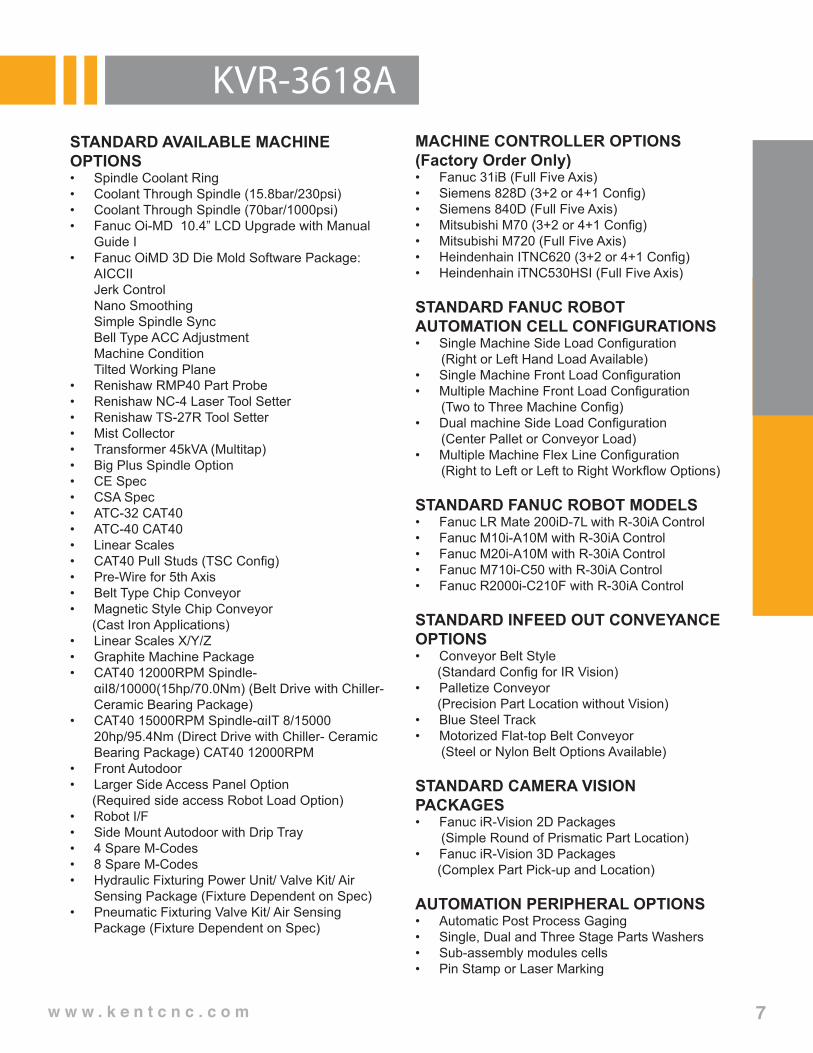
STANDARD AVAILABLE MACHINE OPTIONS• Spindle Coolant Ring• Coolant Through Spindle (15.8bar/230psi)• Coolant Through Spindle (70bar/1000psi)• Fanuc Oi-MD 10.4” LCD Upgrade with Manual
Guide I• Fanuc OiMD 3D Die Mold Software Package: AICCII Jerk Control Nano Smoothing Simple Spindle Sync Bell Type ACC Adjustment Machine Condition Tilted Working Plane• Renishaw RMP40 Part Probe• Renishaw NC-4 Laser Tool Setter• Renishaw TS-27R Tool Setter• Mist Collector• Transformer 45kVA (Multitap)• Big Plus Spindle Option• CE Spec• CSA Spec• ATC-32 CAT40• ATC-40 CAT40• Linear Scales• CAT40 Pull Studs (TSC Config)• Pre-Wire for 5th Axis• Belt Type Chip Conveyor• Magnetic Style Chip Conveyor (Cast Iron Applications)• Linear Scales X/Y/Z • Graphite Machine Package• CAT40 12000RPM Spindle-
αiI8/10000(15hp/70.0Nm) (Belt Drive with Chiller-Ceramic Bearing Package)
• CAT40 15000RPM Spindle-αiIT 8/15000 20hp/95.4Nm (Direct Drive with Chiller- Ceramic Bearing Package) CAT40 12000RPM
• Front Autodoor• Larger Side Access Panel Option (Required side access Robot Load Option)• Robot I/F• Side Mount Autodoor with Drip Tray• 4 Spare M-Codes• 8 Spare M-Codes• Hydraulic Fixturing Power Unit/ Valve Kit/ Air
Sensing Package (Fixture Dependent on Spec)• Pneumatic Fixturing Valve Kit/ Air Sensing
Package (Fixture Dependent on Spec)
MACHINE CONTROLLER OPTIONS(Factory Order Only)• Fanuc 31iB (Full Five Axis)• Siemens 828D (3+2 or 4+1 Config)• Siemens 840D (Full Five Axis)• Mitsubishi M70 (3+2 or 4+1 Config)• Mitsubishi M720 (Full Five Axis)• Heindenhain ITNC620 (3+2 or 4+1 Config)• Heindenhain iTNC530HSI (Full Five Axis)
STANDARD FANUC ROBOTAUTOMATION CELL CONFIGURATIONS• Single Machine Side Load Configuration (Right or Left Hand Load Available)• Single Machine Front Load Configuration• Multiple Machine Front Load Configuration (Two to Three Machine Config)• Dual machine Side Load Configuration (Center Pallet or Conveyor Load)• Multiple Machine Flex Line Configuration (Right to Left or Left to Right Workflow Options)
STANDARD FANUC ROBOT MODELS• Fanuc LR Mate 200iD-7L with R-30iA Control• Fanuc M10i-A10M with R-30iA Control• Fanuc M20i-A10M with R-30iA Control• Fanuc M710i-C50 with R-30iA Control• Fanuc R2000i-C210F with R-30iA Control
STANDARD INFEED OUT CONVEYANCE OPTIONS • Conveyor Belt Style (Standard Config for IR Vision)• Palletize Conveyor (Precision Part Location without Vision)• Blue Steel Track• Motorized Flat-top Belt Conveyor (Steel or Nylon Belt Options Available)
STANDARD CAMERA VISION PACKAGES• Fanuc iR-Vision 2D Packages (Simple Round of Prismatic Part Location)• Fanuc iR-Vision 3D Packages (Complex Part Pick-up and Location)
AUTOMATION PERIPHERAL OPTIONS• Automatic Post Process Gaging• Single, Dual and Three Stage Parts Washers• Sub-assembly modules cells• Pin Stamp or Laser Marking

w w w . k e n t c n c . c o m
KVR-3618A
8
Standard CAD/ CAM Packages
HSM CAM Package for Solidworks• HSM CAM Package #1 (Solidworks Add-In) HSM Works 1) 3 Axis Milling 2) 3+2 Milling 3) Turning• HSM CAM Package #2 (Solidworks Add-In) HSM Works 1) 5 Axis Simutaneous Milling 2) Lathe Rotary Milling 3) 3 Axis Milling 4) 3+2 Milling 5) Turning• Packages are designed for versions Solidwork
2013 and greater.
HSM CAD/CAM Package for Inventor• HSM CAD/CAM Package #1 Autocad 2015 Inventor 2015 HSM Works 1) 3 Axis Milling 2) 3+2 Milling 3) Turning • HSM CAD CAM Package #2 Autocad 2015 Inventor 2015 HSM Works 1) 5 Axis Simutaneous Milling 2) Lathe Rotary Milling 3) 3 Axis Milling 4) 3+2 Milling 5) Turning
Gibbscam CAM System(Standard Available Package Modules)• 2 Axis Turning• 2.5 Axis Milling• 2.5D Solid Milling• 3 Axis Milling• 3D Solid Milling• 5 Axis Milling
GSA 4th Axis Rotary Table Options
CNC-120 Series• CNC-120R Single 4th Axis Rotary Table• CNC-120R-2W Dual 4th Axis Rotary Table• CNC-120R-3W Triple 4th Axis Rotary Table• Motor, Drive and Cable Management Package
CNC-170 Series• CNC-170R Single 4th Axis Rotary Table• CNC-170R-2W Dual 4th Axis Rotary Table• CNC-170R-3W Triple 4th Axis Rotary Table• Motor, Drive and Cable Management Package
CNC-200 Series• CNC-200R Single 4th Axis Rotary Table• CNC-200R-2W Dual 4th Axis Rotary Table• CNC-200R-3W Triple 4th Axis Rotary Table• Motor, Drive and Cable Management Package
CNC-250 Series• CNC-250R Single 4th Axis Rotary Table• CNC-250R-2W Dual 4th Axis Rotary Table• Motor, Drive and Cable Management Package
CNC 4th Axis Table Peripherals• Manual Tailstock (Part #TS-AXXX or TS-BXXX)• Pneumatic Tailstock (Part #TS-AXXXP or TS-BXXXP)• Hydraulic Tailstock (Part #TS-AXXXH or TSB-XXXH)• Workspindle with Hydraulic or Pneumatic Braking (Part # TSA-XXXS)• Manual Scroll Chuck Package• (Part # SC-X)• Hydraulic Chuck Package (Non-Through Hole) (Part # V-XXX)• Hydraulic Clamping Cylinder with Rotary Union (Part # MH-XXX)
GSA 4th/5th Axis Rotary Table Options
CNC-T100 Series• CNC-T100 4th/5th Axis Rotary Table• Motor, Drive and Cable Management Package
CNC-T200 Series• CNC-T200 4th/5th Axis Rotary Table• Motor, Drive and Cable Management Package
w w w . k e n t c n c . c o m
KVR-3618A
9
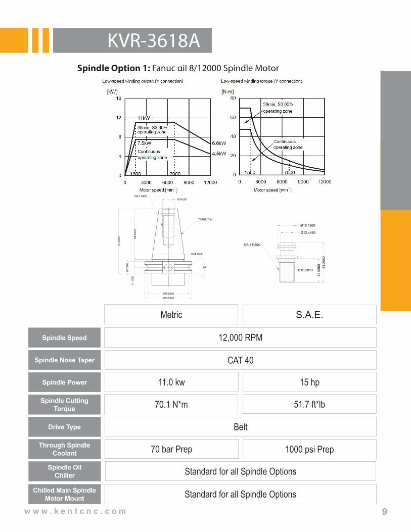
Spindle Speed
Spindle Cutting Torque
Spindle Nose Taper
Drive Type
Spindle Power
Through Spindle Coolant
Chilled Main SpindleMotor Mount
Spindle OilChiller
12,000 RPM
Metric
70.1 N*m
CAT 40
Belt
11.0 kw
70 bar Prep
Standard for all Spindle Options
Standard for all Spindle Options
S.A.E.
51.7 ft*lb
15 hp
1000 psi Prep
Spindle Option 1: Fanuc αiI 8/12000 Spindle Motor
TAPER:7/24
5/8-11UNCØ16.281
Ø55.6000
Ø63.5000
68.2
500
87.3
000
15.7
200
60°
11.1
000
Ø44.4500
5/8-11UNC
Ø12.4460
Ø18.1960
Ø16.2810
25.0
060
41.2
560

w w w . k e n t c n c . c o m
KVR-3618A
10
Spindle Speed
Spindle Cutting Torque
Spindle Nose Taper
Drive Type
Spindle Power
Through Spindle Coolant
Chilled Main SpindleMotor Mount
Spindle OilChiller
15,000 RPM
Metric
70.1 N*m
CAT 40
Direct Drive
11.0 kw
70 bar Prep
Standard for all Spindle Options
Standard for all Spindle Options
S.A.E.
51.7 ft*lb
15 hp
1000 psi Prep
Spindle Option 2: Fanuc αiI 8/15000 Spindle Motor
TAPER:7/24
5/8-11UNCØ16.281
Ø55.6000
Ø63.5000
68.2
500
87.3
000
15.7
200
60°
11.1
000
Ø44.4500
5/8-11UNC
Ø12.4460
Ø18.1960
Ø16.2810
25.0
060
41.2
560

w w w . k e n t c n c . c o m
KVR-3618A
11
CNC-200R Metric S.A.E.Table Diameter 200 mm 7.87 inchCenter Height in Vertical 160 mm 6.3 inchTable Height in Horizontal 165 mm 6.5 inchOverall Height in Vertical Without Motor Cover 265 mm 10.63 inch
Through Hole Diameter 35 H7 mm 1.37 H7 inchWidth of T-Slot 12 H7 mm 0.47 H7 inchWidth of Guide Block 18 H7 mm 0.71 H7 inch
Servo Motor Type
Meldas HF-104TFanuc α4 iSiemens 1FK7060Heidenhain QSY116C
Gear Ratio 1:90Minimum Indexing Unit 0.001°Maximum RPM (Motor: 2000/RPM) 22.2Pneu. Clamp Force (kg•m)(P: 5kg/cm2) 25Hydro. Clamp Force (kg•m)(P: 20kg/cm2) 50Indexing Accuracy Class (Sec.) 508 mm 20”Repeatability (Sec.)
Unidirectional 101.6 mm 4”Bidirectional 203.2 mm 8”
Maximum Machining Force 23 kg/m 15 lb/ftNet Weight 84 kgs 185 lbs
Metric S.A.E.
Maximum Load
Vertical
W = 100 kg W = 170 lbs
Horizontal
W = 200 kg W = 364 lbs
Maximum Radial Load
F = 822 kg F = 1812 lbs
F x L = 13 kg•m
F x L = 28.9 lb/ft
F x L = 50 kg•m
F x L = 33.6 lb/ft
CNC-200R
Table Manufacturing Accuracy StandardsTable top flatness Parallelism of table top and
frame bottomRunout of table spindle center Perpendicularity of table top to
frame bottomTable top runout Perpendicularity of table top to
frame bottom guide blockParallelism of center line
between headstock & tailstock to frame bottom guide block
0.010 mm 0.010 mm 0.010 mm 0.020 mm 0.015 mm 0.020 mm 0.020 mm0.00039 inch 0.00039 inch 0.00039 inch 0.00079 inch 0.00059 inch 0.00079 inch 0.00079 inch

w w w . k e n t c n c . c o m
KVR-3618A
12
CNC-200R

w w w . k e n t c n c . c o m
KVR-3618A
13
CNC-200R Manual Tailstock
Pneumatic Tailstock
Hydraulic Tailstock
A B C Center Taper
TS-A160 160 (6.3) 18 (0.71) 210 (8.3) MT #2
A B C Center Taper
TS-A160P 160 (6.3) 18 (0.71) 217 (8.5) MT #2
A B C Center Taper
TS-A160H 160 (6.3) 18 (0.71) 193 (7.6) MT #2
mm (inch)

w w w . k e n t c n c . c o m
KVR-3618A
14
CNC-200R Work Support Spindle
TSA-200S Metric S.A.E.Table Diameter Ø200 mm 7.9 inch(A) Center Height in Vertical 160 mm 6.3 inch(B) Overall Height in Vertical 265 mm 10.4 inchThrough Hole Diameter Ø35 mm 1.38 inchWidth of T-Slot 12H7 mm 0.47H7 inchWidth of Guide Block 18H7 mm 0.71H7 inchPneumatic Clamp Force 25 (Power 5kg/cm2)Hydraulic Clamp Force 50 (Power 20kg/cm2)Net Weight 45 kgs 99 lbs
Chuck / Hydraulic Cylinder / Tailstock with Rotary Table Application
Manual Scroll Chuck Hydraulic Chuck (Non Through Hole)
Rotary Hydraulic Cylinder
Model No. Size Model No. Size Model No.CNC-200R SC-7 7” V-206 6” MH-100
w w w . k e n t c n c . c o m
KVR-3618A
15
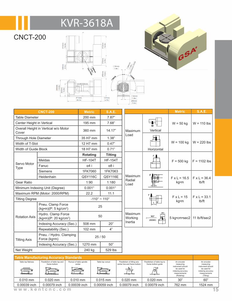
CNCT-200
Metric S.A.E.
Maximum Load
Vertical
W = 50 kg W = 110 lbs
Horizontal
W = 100 kg W = 220 lbs
Maximum Radial Load
F = 500 kg F = 1102 lbs
F x L = 16.5 kg•m
F x L = 36.4 lb/ft
F x L = 15 kg•m
F x L = 33.1 lb/ft
Maximum Working Inertia
5 kg•cm•sec2 11 lb/ft/sec2
Table Manufacturing Accuracy StandardsTable top flatness Parallelism of table top and
frame bottomRunout of table spindle
centerTable top runout Parallelism of tilting axis
center line and frame bottomParallelism of table top to
frame bottom guideAn encodermeasuring
instrument shouldbe used for
indexing accuracymeasurements
(Rotating)
An encodermeasuring
instrument shouldbe used for
indexing accuracymeasurements
(Tilting)
0.010 mm 0.020 mm 0.010 mm 0.015 mm 0.020 mm 0.020 mm 30” 60”0.00039 inch 0.00079 inch 0.00039 inch 0.00059 inch 0.00079 inch 0.00079 inch 762 mm 1524 mm
CNCT-200 Metric S.A.E.Table Diameter 200 mm 7.87”Center Height in Vertical 195 mm 7.68”Overall Height in Vertical w/o Motor Cover 360 mm 14.17”
Through Hole Diameter 35 H7 mm 1.38”Width of T-Slot 12 H7 mm 0.47”Width of Guide Block 18 H7 mm 0.71”
Servo Motor Type
Rotating TiltingMeldas HF-104T HF-154TFanuc α4 i α8 iSiemens 1FK7060 1FK7063Heidenhain QSY116C QSY116E
Gear Ratio 1:90 1:180Minimum Indexing Unit (Degree) 0.001° 0.001°Maximum RPM (Motor: 2000/RPM) 22.2 11.1Tilting Degree -110° ~ 110°
Rotation Axis
Pneu. Clamp Force (kg•m)(P: 5 kg/cm2) 25
Hydro. Clamp Force (kg•m)(P: 20 kg/cm2) 50
Indexing Accuracy (Sec.) 508 mm 20”Repeatability (Sec.) 102 mm 4”
Tilting AxisPneu. / Hydro. Clamping Force (kg•m) 25 / 50
Indexing Accuracy (Sec.) 1270 mm 50”Net Weight 240 kg 529 lbs

w w w . k e n t c n c . c o m
KVR-3618A
16
CNCT-200

17
Kent CNC, Division ofKent Industrial USA Inc.1231 Edinger AvenueTustin, CA 92780 USATel: (714) 258-8526Fax: (714) 258-8530E-mail Inquiry:[email protected]:www.kentcnc.com
V2015.5
Manufacturing • Automation • Production • Engineering • Solutions