COMPACT TYPE GAS ANALYZER -...
51
Service Manual INZ-TN5A0150a-E COMPACT TYPE GAS ANALYZER TYPE: ZFG
Transcript of COMPACT TYPE GAS ANALYZER -...
Service Manual
INZ-TN5A0150a-E
COMPACT TYPE
GAS ANALYZER
TYPE: ZFG
INZ-TN5A0150-E i
PREFACE
This service manual for the compact type gas analyzer (type ZFG) describes the factory mode for
maintenance and inspection, method of adjustment to be performed after parts replacement, and measures to
be taken in case of occurrence of troubles.
The manual does not describe basic operations of the gas analyzer. Be sure to read the manual carefully
before performing maintenance and inspection.
This service manual gives you useful hints to take immediate remedy for after-sales service.
First read the instruction manual and service manual carefully until an adequate understanding
is acquired, and then proceed to installation, operation and maintenance of the gas analyzer.
Wrong handling may cause an accident or injury.
The specifications of this gas analyzer will be changed without prior notice for further product
improvement.
Modification of this gas analyzer is strictly prohibited unless a written approval is obtained from
the manufacturer. Fuji Electric will not bear any responsibility for a trouble caused by such a
modification.
Manufacturer: Fuji Electric Co., Ltd.
Type: Described in the nameplate on main frame
Date of manufacture: Described in the nameplate on main frame
Product nationality: Japan
It is prohibited to transfer part or all of this manual without
Fuji's permission in written format.
Description in this manual will be changed without prior
notice for further improvement.
Request ©Fuji Electric Co., Ltd.
Issued in February, 2008
Rev. 1st edition April, 2011
ii INZ-TN5A0150-E
CONTENTS PREFACE............................................................................................................................................. i CAUTION ON SAFETY ...................................................................................................................iii 1. NAME OF MAIN DEVICES AND SERVICE PARTS...................................................................... 1
1.1 Case and electrical parts..................................................................................................................... 1 1.2 Measurement unit............................................................................................................................... 2
2. MAINTENANCE, INSPECTION, AND ADJUSTMENT AFTER REPAIR AND REPLACEMENT .................................................................................................................................. 3
2.1 Liquid crystal display unit.................................................................................................................. 3 2.2 Sheet key (Membrane switch)............................................................................................................ 5 2.3 Amplifier printed circuit board .......................................................................................................... 6 2.4 Main printed circuit board.................................................................................................................. 8 2.5 Power supply.................................................................................................................................... 10 2.6 Light source unit .............................................................................................................................. 12 2.7 Cell, cell window, and O-ring .......................................................................................................... 14 2.8 Detector ............................................................................................................................................ 16 2.9 Gas filter........................................................................................................................................... 19
3. FACTORY MODE.............................................................................................................................. 21 3.1 How to go to Factory Mode ............................................................................................................. 21 3.2 How to go to each item in Factory Mode......................................................................................... 22 3.3 Setting item in Factory Mode........................................................................................................... 23
3.3.1 Language setting .....................................................................................................................23 3.3.2 Number of channels (Measured component setting)...............................................................24 3.3.3 Channel parameter (setting of range and unit) ........................................................................25 3.3.4 Output option ..........................................................................................................................26 3.3.5 Zero offset ...............................................................................................................................27 3.3.6 Linearizer ................................................................................................................................28 3.3.7 Temperature compensation......................................................................................................29 3.3.8 Output selection.......................................................................................................................32 3.3.9 Output adjustment ...................................................................................................................33 3.3.10 Memory rewrite ...................................................................................................................34 3.3.11 Coefficient confirmation......................................................................................................36 3.3.12 A/D data...............................................................................................................................37
4. ERROR JUDGEMENT CRITERIA FOR ERROR CODES ..................................................................... 38 5. MEASURING PRINCIPLE DIAGRAM ........................................................................................... 39 6. SOFT FLOW CHART ........................................................................................................................ 40 7. INTERNAL WIRING DIAGRAM..................................................................................................... 41 8. INTERNAL PIPING ........................................................................................................................... 42 9. PRINTED CIRCUIT BOARD DIAGRAM ....................................................................................... 43
9.1 Amplifier printed circuit board ........................................................................................................ 43 9.2 Output printed circuit board ............................................................................................................. 43 9.3 Main printed circuit board................................................................................................................ 44
INZ-TN5A0150-E iii
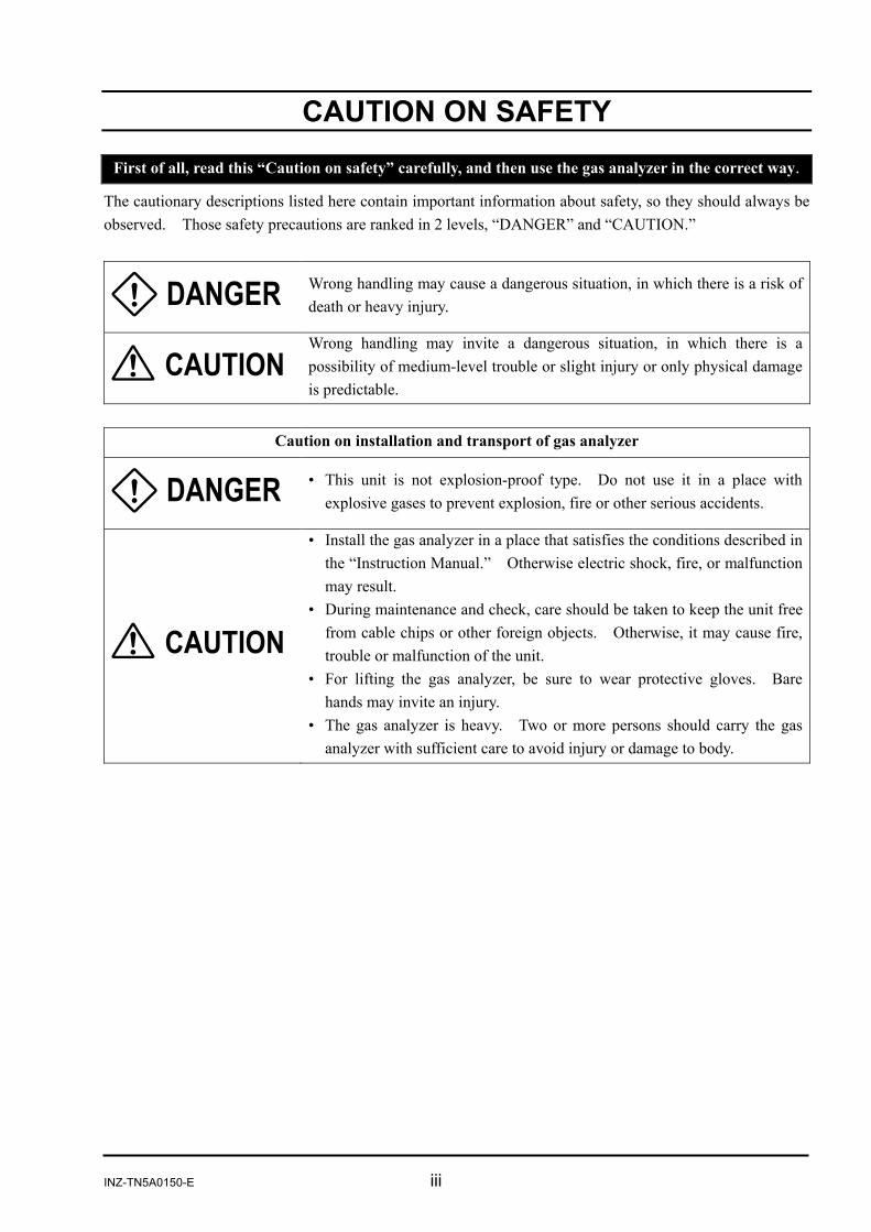
CAUTION ON SAFETY
First of all, read this “Caution on safety” carefully, and then use the gas analyzer in the correct way.
The cautionary descriptions listed here contain important information about safety, so they should always be observed. Those safety precautions are ranked in 2 levels, “DANGER” and “CAUTION.”
Wrong handling may cause a dangerous situation, in which there is a risk of death or heavy injury.
Wrong handling may invite a dangerous situation, in which there is a possibility of medium-level trouble or slight injury or only physical damage is predictable.
Caution on installation and transport of gas analyzer
• This unit is not explosion-proof type. Do not use it in a place with explosive gases to prevent explosion, fire or other serious accidents.
• Install the gas analyzer in a place that satisfies the conditions described in the “Instruction Manual.” Otherwise electric shock, fire, or malfunction may result.
• During maintenance and check, care should be taken to keep the unit free from cable chips or other foreign objects. Otherwise, it may cause fire, trouble or malfunction of the unit.
• For lifting the gas analyzer, be sure to wear protective gloves. Bare hands may invite an injury.
• The gas analyzer is heavy. Two or more persons should carry the gas analyzer with sufficient care to avoid injury or damage to body.
iv INZ-TN5A0150-E
Caution on piping
In piping, the following precautions should be observed. Wrong piping may cause gas leakage. If the leaking gas contains a toxic component, there is a risk of serious accident being induced. Also, if combustible gas is contained, there is a danger of explosion, fire or the like occurring. • Connect pipes correctly referring to the instruction manual. • Exhaust should be led outdoors so that it will not remain indoors. • Exhaust from the gas analyzer should be relieved in the atmospheric air
in order that an unnecessary pressure will not be applied to the gas analyzer. Otherwise, any pipe in the gas analyzer may be disconnected to cause gas leakage.
• For piping, use a pipe and a pressure reducing valve to which oil and grease are not adhering. If such a material is adhering, a fire or the like accident may be caused.
Caution on wiring
• Be sure to perform specified grounding work to avoid electric shock or malfunction.
• Be sure to use a power supply of correct rating. Connection of power supply of incorrect rating may cause fire.
• Wiring work must be performed with the main power set to OFF to prevent electric shocks.
• Wires should be the proper one meeting the ratings of this instrument. If using a wire which cannot endure the ratings, a fire may occur.
Caution on use
• For correct handling of calibration gas or other reference gases, carefully read their instruction manuals beforehand.
• Do not operate the gas analyzer continuously with the cover opened.Otherwise dust may enter, causing a failure.
• Do not open the cover and touch inside while the gas analyzer is operated. Otherwise burns or electric shock may result.
INZ-TN5A0150-E v
Caution on maintenance and check
• Before performing work with the cover opened, be sure to turn off the power and purge fully not only the gas analyzer but also measurement gas lines with air and N2 gas. Be careful not to stain the inside of piping with oil or grease. Otherwise gas leak may occur, thus causing poisoning, fire, or explosion.
• Be sure to remove metallic objects such as a wristwatch or a ring.Never perform work with wet hands to avoid electric shock.
• If the fuse is blown, eliminate the cause, and then replace it with the one of the same capacity and type as before. Otherwise, shock hazard or fault may be caused.
Others
• If the cause of any fault cannot be determined despite reference to the instruction manual, be sure to contact your dealer or Fuji Electric’s technician in charge of adjustment. If the instrument is disassembled carelessly, you may have a shock hazard or injury.
• Do not use replacement parts not specified by the manufacturer.Otherwise sufficient performance of the gas analyzer may not be obtained, or accidents or failure may result.
• Dispose the parts removed for maintenance as noncombustible waste.
INZ-TN5A0150-E 1
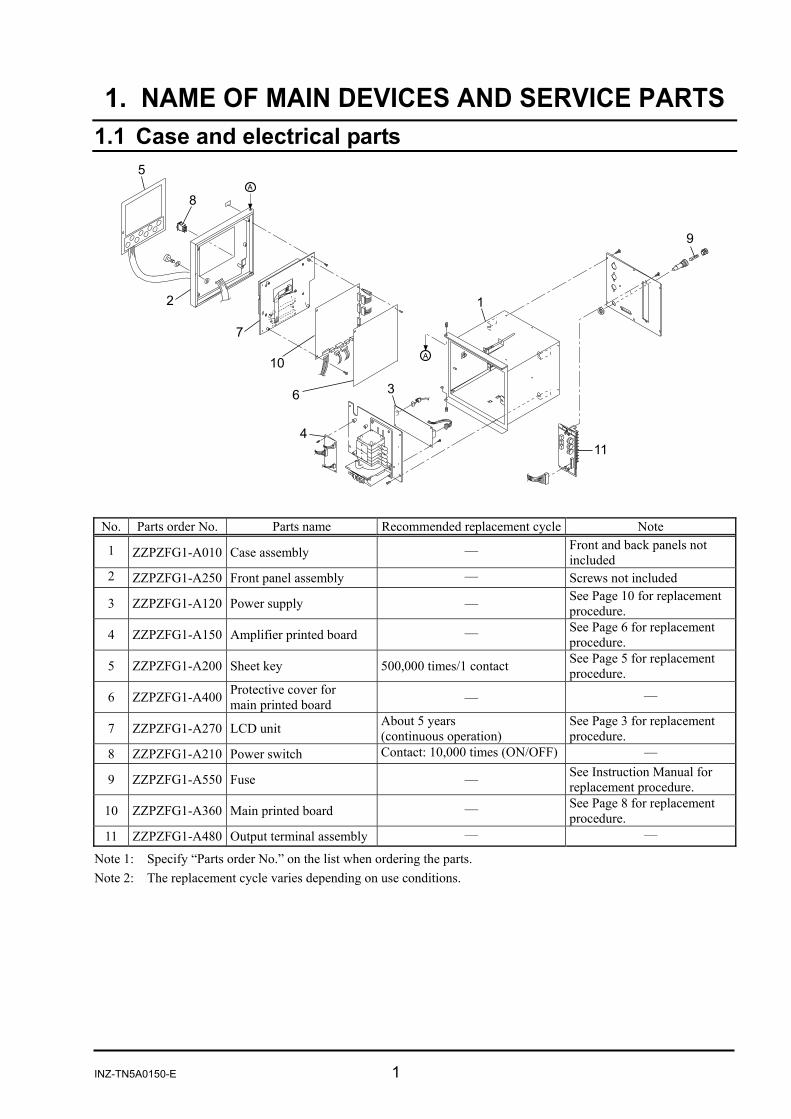
1. NAME OF MAIN DEVICES AND SERVICE PARTS 1.1 Case and electrical parts
No. Parts order No. Parts name Recommended replacement cycle Note
1 ZZPZFG1-A010 Case assembly — Front and back panels not included
2 ZZPZFG1-A250 Front panel assembly — Screws not included
3 ZZPZFG1-A120 Power supply — See Page 10 for replacement procedure.
4 ZZPZFG1-A150 Amplifier printed board — See Page 6 for replacement procedure.
5 ZZPZFG1-A200 Sheet key 500,000 times/1 contact See Page 5 for replacement procedure.
6 ZZPZFG1-A400 Protective cover for main printed board — —
7 ZZPZFG1-A270 LCD unit About 5 years (continuous operation)
See Page 3 for replacement procedure.
8 ZZPZFG1-A210 Power switch Contact: 10,000 times (ON/OFF) —
9 ZZPZFG1-A550 Fuse — See Instruction Manual for replacement procedure.
10 ZZPZFG1-A360 Main printed board — See Page 8 for replacement procedure.
11 ZZPZFG1-A480 Output terminal assembly — —
Note 1: Specify “Parts order No.” on the list when ordering the parts. Note 2: The replacement cycle varies depending on use conditions.
2 INZ-TN5A0150-E
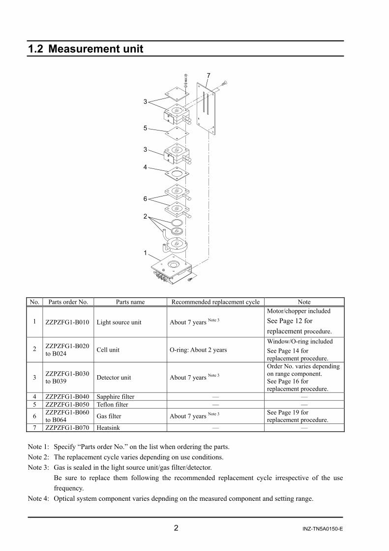
1.2 Measurement unit
No. Parts order No. Parts name Recommended replacement cycle Note
1 ZZPZFG1-B010 Light source unit About 7 years Note 3
Motor/chopper included See Page 12 for replacement procedure.
2 ZZPZFG1-B020 to B024 Cell unit O-ring: About 2 years
Window/O-ring included See Page 14 for replacement procedure.
3 ZZPZFG1-B030 to B039 Detector unit About 7 years Note 3
Order No. varies depending on range component. See Page 16 for replacement procedure.
4 ZZPZFG1-B040 Sapphire filter — — 5 ZZPZFG1-B050 Teflon filter — —
6 ZZPZFG1-B060 to B064 Gas filter About 7 years Note 3 See Page 19 for
replacement procedure. 7 ZZPZFG1-B070 Heatsink — —
Note 1: Specify “Parts order No.” on the list when ordering the parts. Note 2: The replacement cycle varies depending on use conditions. Note 3: Gas is sealed in the light source unit/gas filter/detector.
Be sure to replace them following the recommended replacement cycle irrespective of the use frequency.
Note 4: Optical system component varies depnding on the measured component and setting range.
3 TN5A0150-E
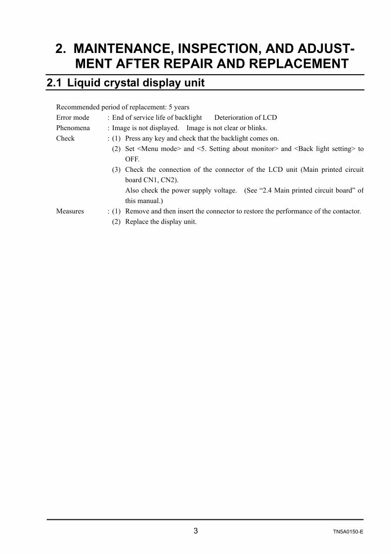
2. MAINTENANCE, INSPECTION, AND ADJUST-MENT AFTER REPAIR AND REPLACEMENT
2.1 Liquid crystal display unit
Recommended period of replacement: 5 years Error mode : End of service life of backlight Deterioration of LCD Phenomena : Image is not displayed. Image is not clear or blinks. Check : (1) Press any key and check that the backlight comes on. (2) Set <Menu mode> and <5. Setting about monitor> and <Back light setting> to
OFF. (3) Check the connection of the connector of the LCD unit (Main printed circuit
board CN1, CN2). Also check the power supply voltage. (See “2.4 Main printed circuit board” of
this manual.) Measures : (1) Remove and then insert the connector to restore the performance of the contactor. (2) Replace the display unit.

4 INZ-TN5A0150-E
Replacement : (1) Remove the cable connected to the main printed circuit board off the connectors(CN1 to CN8, and CN10).
(2) Remove the fastening screw (2-M3×6 screws) and detach the protective cover and spacer.
(3) Remove the fastening screw (2-M3×6 screws) from LCD mounting plate, and detach the main printed circuit board.
(4) Remove the cable from the inverter. Remove the tapping screws (4-M3×5), and replace the LCD unit with a new one.
! Caution on replacement
(1) Be sure to turn off the power before removing and inserting the connector to avoid damage to the display drive IC, etc.
INZ-TN5A0150-E 5
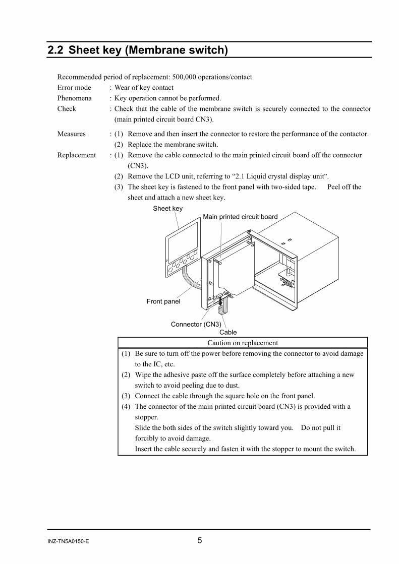
2.2 Sheet key (Membrane switch)
Recommended period of replacement: 500,000 operations/contact Error mode : Wear of key contact Phenomena : Key operation cannot be performed. Check : Check that the cable of the membrane switch is securely connected to the connector
(main printed circuit board CN3).
Measures : (1) Remove and then insert the connector to restore the performance of the contactor. (2) Replace the membrane switch. Replacement : (1) Remove the cable connected to the main printed circuit board off the connector
(CN3). (2) Remove the LCD unit, referring to “2.1 Liquid crystal display unit”. (3) The sheet key is fastened to the front panel with two-sided tape. Peel off the
sheet and attach a new sheet key.
Caution on replacement
(1) Be sure to turn off the power before removing the connector to avoid damage to the IC, etc.
(2) Wipe the adhesive paste off the surface completely before attaching a new switch to avoid peeling due to dust.
(3) Connect the cable through the square hole on the front panel. (4) The connector of the main printed circuit board (CN3) is provided with a
stopper. Slide the both sides of the switch slightly toward you. Do not pull it
forcibly to avoid damage. Insert the cable securely and fasten it with the stopper to mount the switch.
6 INZ-TN5A0150-E
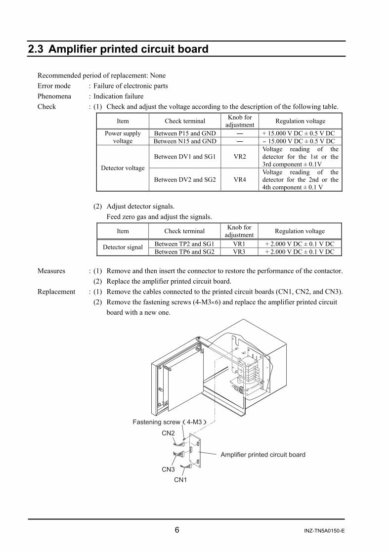
2.3 Amplifier printed circuit board
Recommended period of replacement: None Error mode : Failure of electronic parts Phenomena : Indication failure Check : (1) Check and adjust the voltage according to the description of the following table.
Item Check terminal Knob for
adjustment Regulation voltage
Between P15 and GND ― + 15.000 V DC ± 0.5 V DC Power supply voltage Between N15 and GND ― - 15.000 V DC ± 0.5 V DC
Between DV1 and SG1 VR2 Voltage reading of the detector for the 1st or the 3rd component ± 0.1V Detector voltage
Between DV2 and SG2 VR4 Voltage reading of the detector for the 2nd or the 4th component ± 0.1 V
(2) Adjust detector signals. Feed zero gas and adjust the signals.
Item Check terminal Knob for
adjustment Regulation voltage
Between TP2 and SG1 VR1 + 2.000 V DC ± 0.1 V DC Detector signal Between TP6 and SG2 VR3 + 2.000 V DC ± 0.1 V DC
Measures : (1) Remove and then insert the connector to restore the performance of the contactor. (2) Replace the amplifier printed circuit board. Replacement : (1) Remove the cables connected to the printed circuit boards (CN1, CN2, and CN3).
(2) Remove the fastening screws (4-M3×6) and replace the amplifier printed circuit board with a new one.
( )
INZ-TN5A0150-E 7
Adjustment after replacement: (1) Insert connector CN3 only. (Do not insert CN1 or CN2.)
(2) Insert the jumper pins (JP1 and JP2) into the same position as the old printed circuit board.
(3) Turn on the power and check and adjust “power supply voltage” and “detector voltage.”
(4) Turn off the power and insert connectors CN1 and CN2. (5) Turn on the power again, and adjust “detector signals.” (6) Perform zero and span calibrations to complete the work.
Caution on replacement (1) Be sure to turn off the power before removing and inserting the connector to
avoid damage to the detector. (2) Be careful not to cause short circuit with other parts while checking and
adjusting the voltage. (3) Be sure to warm up the instrument fully before adjusting detector signals.
8 INZ-TN5A0150-E
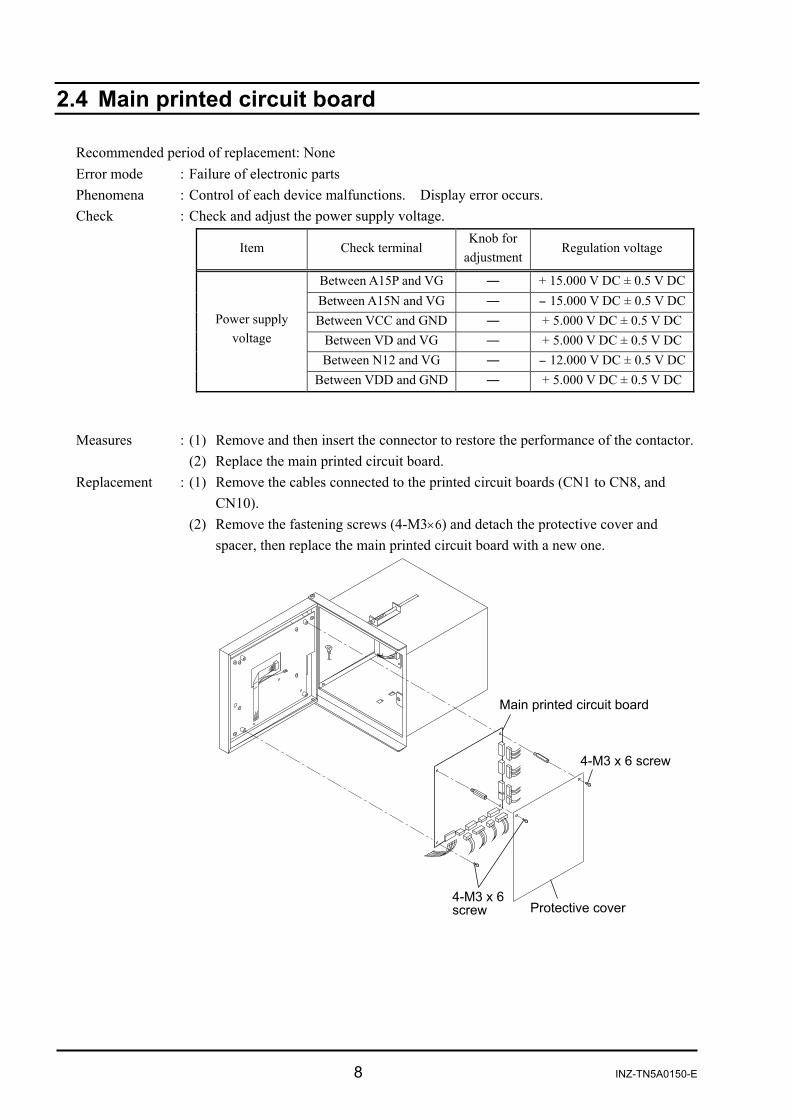
2.4 Main printed circuit board
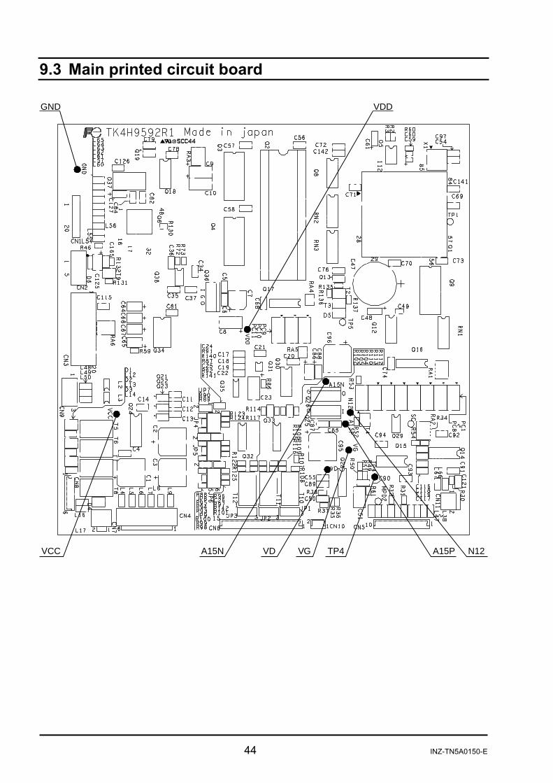
Recommended period of replacement: None Error mode : Failure of electronic parts Phenomena : Control of each device malfunctions. Display error occurs. Check : Check and adjust the power supply voltage.
Item Check terminal Knob for
adjustmentRegulation voltage
Between A15P and VG ― + 15.000 V DC ± 0.5 V DCBetween A15N and VG ― - 15.000 V DC ± 0.5 V DCBetween VCC and GND ― + 5.000 V DC ± 0.5 V DC
Between VD and VG ― + 5.000 V DC ± 0.5 V DCBetween N12 and VG ― - 12.000 V DC ± 0.5 V DC
Power supply voltage
Between VDD and GND ― + 5.000 V DC ± 0.5 V DC
Measures : (1) Remove and then insert the connector to restore the performance of the contactor. (2) Replace the main printed circuit board. Replacement : (1) Remove the cables connected to the printed circuit boards (CN1 to CN8, and
CN10). (2) Remove the fastening screws (4-M3×6) and detach the protective cover and
spacer, then replace the main printed circuit board with a new one.

INZ-TN5A0150-E 9
Data input and adjustment after replacement:
(1) Enter all the setting data for <Menu mode>/<Maintenance mode> manually. (See the instruction manual for details of each mode.)
(2) Enter the data for <Factory mode> manually. (See <Description of factory mode> in Chapter 3 of this manual.)
(3) Perform offset adjustment. 1) Turn off the power and remove CN1 and CN2 of the amplifier printed circuit
board (detector signal open). 2) Turn on the power, and make <Factory mode> and <5. Zero offset> settings. 3) Turn off the power again, and connect CN1 and CN2 on the amplifier printed
circuit board. (4) Perform zero and span calibrations to complete the work.
Caution on replacement 1) Be sure to turn off the power before removing and inserting the connector to
prevent damage to electronic parts. 2) Be careful not to cause short circuit with other parts while checking the
voltage. 3) We recommend you to order a main printed circuit board with data already
entered. Specify “Date of manufacture,” “Serial No.” and “Type” when placing your order.

10 INZ-TN5A0150-E
2.5 Power supply
Recommended period of replacement: None Error mode : Specified power supply voltage is not output. Phenomena : Image is not displayed. Display is not clear. Analog output is not produced. Check : (1) Check the power supply voltage. (See “2.4 Main printed circuit board” of this
manual.) (2) Check the connection of the power supply connector. (3) Check that the fuse is not blown.
Measures : (1) Remove and then insert the connector to restore the performance of the contactor. (2) Replace the power supply.

INZ-TN5A0150-E 11
Replacement : (1) Remove the back panel (6-M3 × 6). (2) Remove the cables connected to the power supply (CN1 and CN2). (3) Remove the fastening screws from the power supply board (4-M3×6 screws) and
replace the power supply with a new one.
Caution on replacement
(1) Be sure to turn off the power before removing and inserting the connector to avoid damage to the parts.
12 INZ-TN5A0150-E
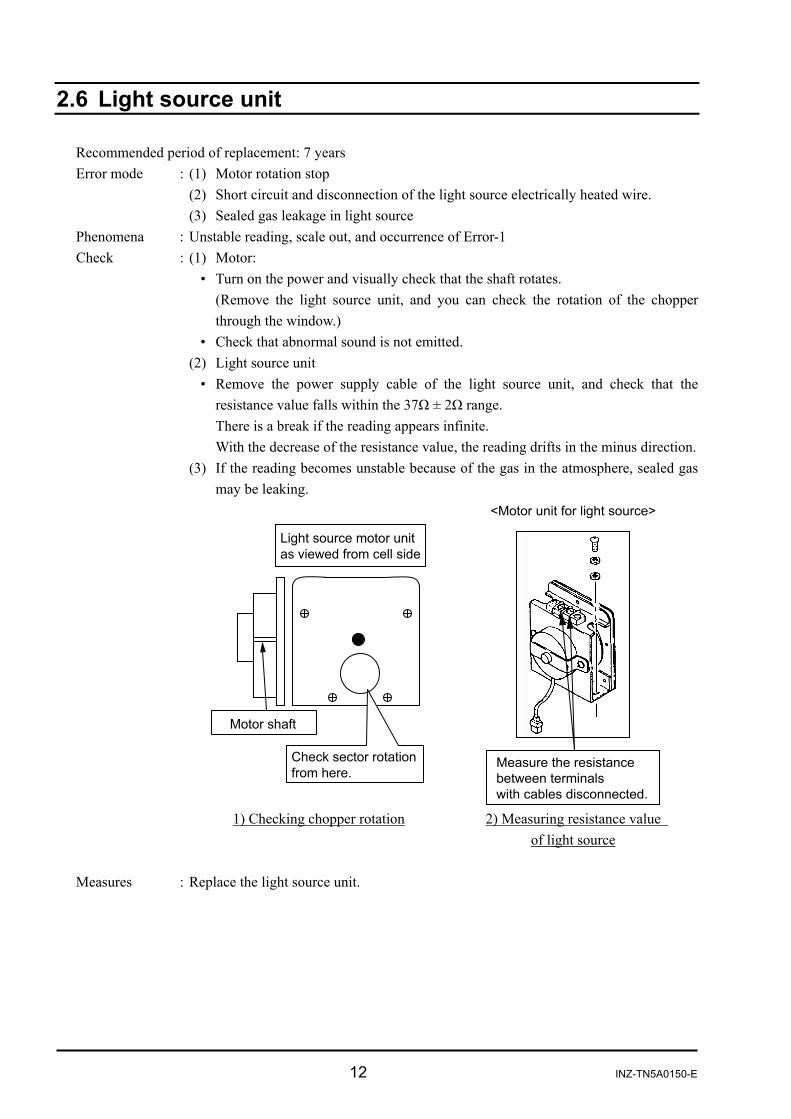
2.6 Light source unit
Recommended period of replacement: 7 years Error mode : (1) Motor rotation stop (2) Short circuit and disconnection of the light source electrically heated wire. (3) Sealed gas leakage in light source Phenomena : Unstable reading, scale out, and occurrence of Error-1 Check : (1) Motor: • Turn on the power and visually check that the shaft rotates.
(Remove the light source unit, and you can check the rotation of the chopperthrough the window.)
• Check that abnormal sound is not emitted. (2) Light source unit • Remove the power supply cable of the light source unit, and check that the
resistance value falls within the 37Ω ± 2Ω range. There is a break if the reading appears infinite.
With the decrease of the resistance value, the reading drifts in the minus direction. (3) If the reading becomes unstable because of the gas in the atmosphere, sealed gas
may be leaking.
1) Checking chopper rotation 2) Measuring resistance value
of light source Measures : Replace the light source unit.

INZ-TN5A0150-E 13
Replacement : (1) Remove the screw fastening the unit to the optical system baseboard
(4-M4×6 screws). (2) Remove the cell and detector unit from the heatsink (2-M4×6 + lot head screws).(3) Remove the fastening screws (4pcs.) from the cell and detector unit. (4) Remove the light source unit from the heatsink (2-M4×8 screws).
!
"
" #
Adjustment after replacement: Adjust the signals from the detector on the amplifier printed circuit board. (1) Feed zero gas.
Item Check terminal
Knob for adjustment
Regulation voltage
Between TP2 and SG1 VR1 + 2.000 V DC ± 0.1 V DCDetector signal Between TP6 and SG2 VR3 + 2.000 V DC ± 0.1 V DC
(2) Perform zero and span calibrations to complete the work.
Caution on adjustment Be sure to warm up the instrument fully before adjusting detector signals.
14 INZ-TN5A0150-E
2.7 Cell, cell window, and O-ring
Service life : Usable unless contaminated or corroded. Recommended period of replacement: 2 years with O-ring (1) Error mode : Contamination of cell, mixture of foreign matter, and contamination of cell window Phenomena : Scale-out indication, drift and calibration error occurred to gas analyzer Check : Disassemble the cell to assure that the inside is clean. (2) Error mode : Crack in cell window Phenomena : No change in indication, slow response, calibration error, and indication fluctuation Check : Visually check the cell window for damage. Measures : Cell Clean the inside of the cell (refer to the instruction manual for
details). Replace if the inside is exposed to excessive contamination or corrosion.
Cell window Clean the cell window. Replace if the inside is exposed to excessive contamination.
INZ-TN5A0150-E 15
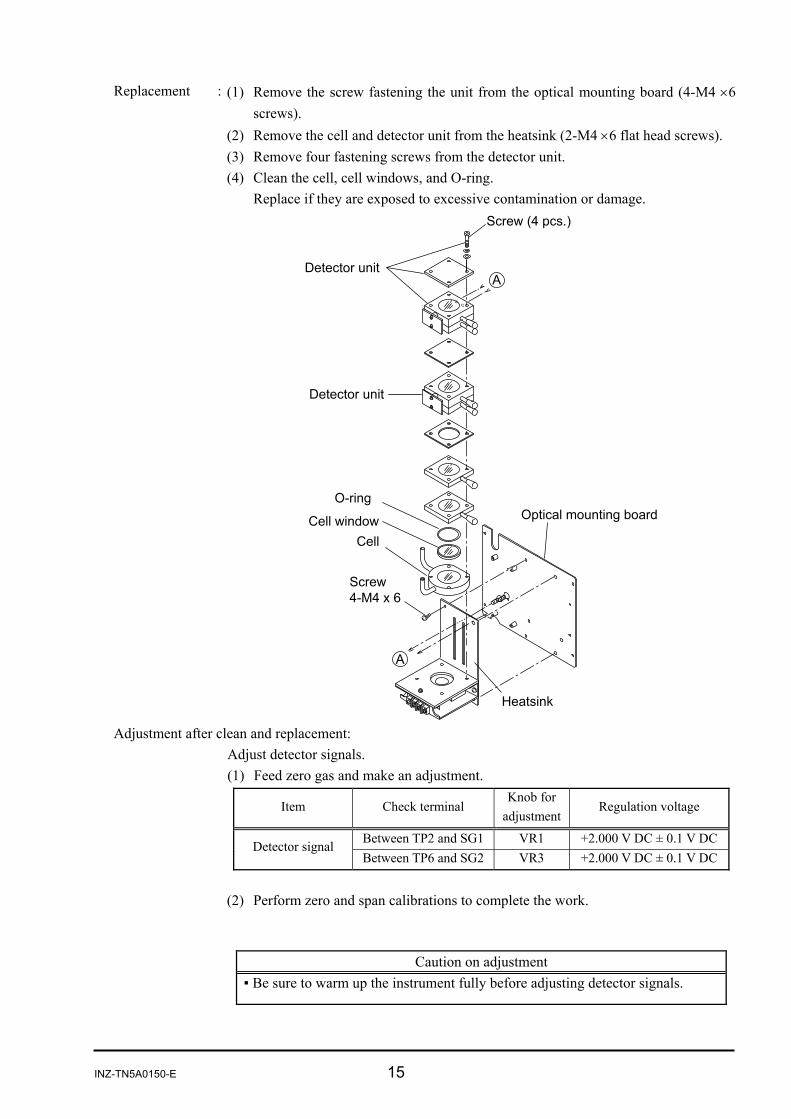
Replacement : (1) Remove the screw fastening the unit from the optical mounting board (4-M4 ×6 screws).
(2) Remove the cell and detector unit from the heatsink (2-M4 ×6 flat head screws). (3) Remove four fastening screws from the detector unit. (4) Clean the cell, cell windows, and O-ring. Replace if they are exposed to excessive contamination or damage.
Adjustment after clean and replacement:
Adjust detector signals. (1) Feed zero gas and make an adjustment.
Item Check terminal Knob for
adjustment Regulation voltage
Between TP2 and SG1 VR1 +2.000 V DC ± 0.1 V DCDetector signal Between TP6 and SG2 VR3 +2.000 V DC ± 0.1 V DC
(2) Perform zero and span calibrations to complete the work.
Caution on adjustment Be sure to warm up the instrument fully before adjusting detector signals.

16 INZ-TN5A0150-E
2.8 Detector
Recommended period of replacement: 7 years (1) Error mode : Damage to mass-flow detector Phenomena : Scale-out indication of the gas analyzer Check : Turn OFF the power of the gas analyzer and disconnect
the connector connected from the detector to amplifier printed circuit board. (Amplifier printed circuit boardCN1, CN2). Measure resistance between 4 – 7 and 5 – 7 of the bridge printed circuit board on the detector. The measure values must be between 25Ω and 60Ω. If the resistance value is fluctuated beyond the specifiedrange, the detector element may be damaged.
Note: Do not use measurement instrument that allows a current of 2 mA or more to be supplied when measuring resistance, otherwise the element can be damaged.
(2) Error mode : Sensitivity deterioration due to sealed gas leak Phenomena : Calibration error and fluctuation in indication Check : Check indication value at zero point
......... Check the indication value for each component on the <Sensor Input Value>screen in the <Maintenance mode>.
If the light source is in normal condition and the cell is free of contamination, thecounter value indicates 38000 to 42000 when zero gas is supplied. If the counter value is below the range, sensitivity can be degraded.
Measures : Replace the detector.

INZ-TN5A0150-E 17
Replacement : (1) Remove the screw fastening the unit from optical mounting board (4-M4×6 screws).
(2) Remove the cell and detector unit from the heatsink (2-M4×6 flat head screws). (3) Remove four fastening screw from the detector unit. (4) Connect the cable solder-mounted on the detector bridge Pt board to the replaced
detector (Refer to Page 16).
!
"

18 INZ-TN5A0150-E
Adjustment after replacement:
Adjust the amplifier printed circuit board. (1) Adjusting the power supply voltage of the detector:
Insert connector CN3 only. (Do not insert CN1 and CN2.) Turn on the power and adjust the “detector voltage” shown below.
Item Check terminalKnob for
adjustment Regulation voltage
Between DV1 and SG1
VR2 Voltage reading of the detector for the 1st component ± 0.1 V
Detector voltage Between DV2
and SG2 VR4
Voltage reading of the detector for the 2nd component ± 0.1 V
(2) Adjusting detector signals:
Feed zero gas. Turn off the power and insert connectors CN1 and CN2. Turn on the power again, and adjust the “detector signals.”
Item Check terminalKnob for
adjustment Regulation voltage
Between TP2 and SG1
VR1 +2.000 V DC ± 0.1 V DC Detector signal
Between TP6 and SG2
VR3 +2.000 V DC ± 0.1 V DC
(3) Perform zero and span calibrations to complete the work.
Note: Adjust the detector voltage on the
printed circuit board and plug the connector into the detector. Do not insert the connector before voltage regulation, or the element may be damaged.
Detector voltage reading
Caution on adjustment Be sure to warm up the instrument fully before adjusting detector signals.
INZ-TN5A0150-E 19
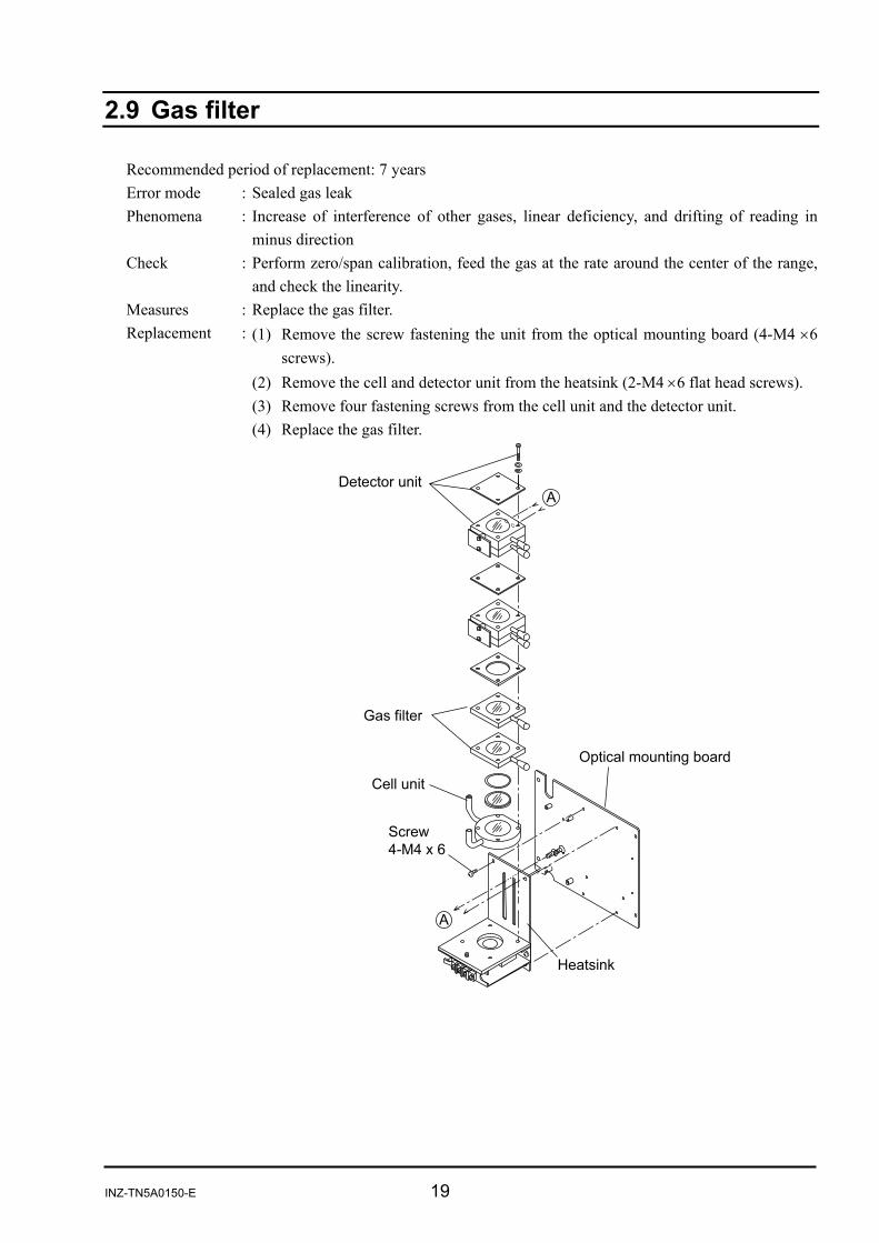
2.9 Gas filter
Recommended period of replacement: 7 years Error mode : Sealed gas leak Phenomena : Increase of interference of other gases, linear deficiency, and drifting of reading in
minus direction Check : Perform zero/span calibration, feed the gas at the rate around the center of the range,
and check the linearity. Measures : Replace the gas filter. Replacement : (1) Remove the screw fastening the unit from the optical mounting board (4-M4 ×6
screws). (2) Remove the cell and detector unit from the heatsink (2-M4 ×6 flat head screws). (3) Remove four fastening screws from the cell unit and the detector unit. (4) Replace the gas filter.

20 INZ-TN5A0150-E
Adjustment after replacement:
Adjust the detector signals of the amplifier printed circuit board. (1) Feed zero gas.
Turn on the power and adjust “detector signals.”
Item Check terminal
Knob for adjustment
Regulation voltage
Between TP2 and SG1 VR1 +2.000 V DC ± 0.1 V DC Detector signal Between TP6 and SG2 VR3 +2.000 V DC ± 0.1 V DC
(2) Perform zero and span calibrations to complete the work.
Caution on adjustment Be sure to warm up the instrument fully before adjusting detector signals.

INZ-TN5A0150-E 21
3. FACTORY MODE 3.1 How to go to Factory Mode
Caution
Factory adjustment is made in this mode. Be careful not to enter wrong settings to avoid malfunction of the analyzer.
Point the cursor to “8. To Factory Mode” by using the or
key on the Maintenance Mode screen and enter the ENT key. Then, the password input screen appears.
ENT Enter the password, “2404.” Select a digit using the key.
Change the value using the or key.
ENT After password entry has been completed, press the ENT key, and the Factory Mode initial screen appears. The cursor is placed at “1. Language” as default.

22 INZ-TN5A0150-E
3.2 How to go to each item in Factory Mode On the factory mode screen that appears, move the cursor tothe item to be set using the , , or key.
ENT ESC
Into each parameter screen To get access to each setting screen, press the ENT key. To return from each setting screen to the initial screen, pressthe ESC key. When escaping from the Factory Mode screen to theMaintenance Mode screen, press the ESC key.
INZ-TN5A0150-E 23
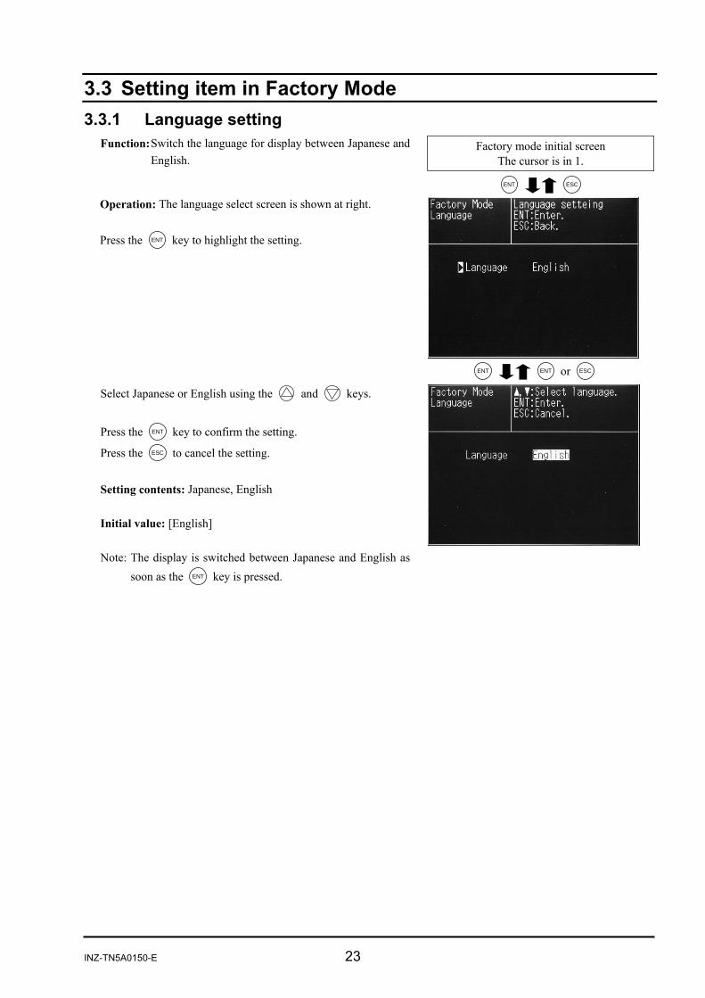
3.3 Setting item in Factory Mode 3.3.1 Language setting
Factory mode initial screen The cursor is in 1.
Function: Switch the language for display between Japanese and English.
ENT ESC Operation: The language select screen is shown at right. Press the ENT key to highlight the setting.
ENT ENT or ESC
Select Japanese or English using the and keys. Press the ENT key to confirm the setting.
Press the ESC to cancel the setting. Setting contents: Japanese, English Initial value: [English] Note: The display is switched between Japanese and English as
soon as the ENT key is pressed.

24 INZ-TN5A0150-E
3.3.2 Number of channels (Measured component setting)
Factory mode initial screen The cursor is in 2.
Function: Set the components for each channel to be displayed on the measurement screen. The setting determines the number of components to be measured. ENT ESC
Operation: The screen for setting the number of channels is shown at right.
Move the cursor to the component to be measured using the
and keys.
Press the ENT key to highlight the name of components selected.
ENT ESC Select a component name using the and keys.
Press the ENT key to confirm the setting.
Press the ESC key to cancel the setting.
Note: Make the setting sequentially beginning from first component. Be sure to select “None” for the optical systems without the sensor. Do not select “None” for all of them. Otherwise A/D conversion failure may result.
Select “ON” or “OFF” for CP calculation value. Initial value : First component =CO2 Second component =CO CP calculation value = OFF (None)
INZ-TN5A0150-E 25
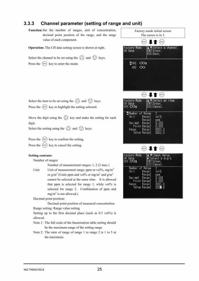
3.3.3 Channel parameter (setting of range and unit)
Factory mode initial screen The cursor is in 3.
Function: Set the number of ranges, unit of concentration, decimal point position of the range, and the range value of each component. ENT ESC
Operation: The CH data setting screen is shown at right. Select the channel to be set using the and keys.
Press the ENT key to enter the mode.
ENT ESC
ENT ESC
Select the item to be set using the and keys.
Press the ENT key to highlight the setting selected. Move the digit using the key and make the setting for each digit. Select the setting using the and keys. Press the ENT key to confirm the setting.
Press the ESC key to cancel the setting. Setting contents:
Number of ranges: Number of measurement ranges; 1, 2 (2 max.) Unit: Unit of measurement range; ppm or vol%, mg/m3 or g/m3 (Units ppm and vol% or mg/m3 and g/m3 cannot be selected at the same time. It is allowed that ppm is selected for range 1, while vol% is selected for range 2. Combination of ppm and mg/m3 is not allowed.) Decimal point position: Decimal point position of measured concentrationRange setting: Range value setting Setting up to the first decimal place (such as 0.5 vol%) is allowed. Note 1: The full scale of the linearization table setting should
be the maximum range of the setting range. Note 2: The ratio of range of range 1 to range 2 is 1 to 5 at
the maximum.
26 INZ-TN5A0150-E
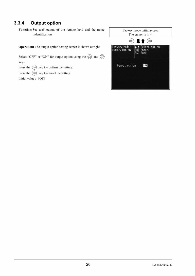
3.3.4 Output option
Factory mode initial screen The cursor is in 4.
Function: Set each output of the remote hold and the range indentification.
ENT ESC Operation: The output option setting screen is shown at right. Select “OFF” or “ON” for output option using the and keys. Press the ENT key to confirm the setting.
Press the ESC key to cancel the setting. Initial value : [OFF]
INZ-TN5A0150-E 27
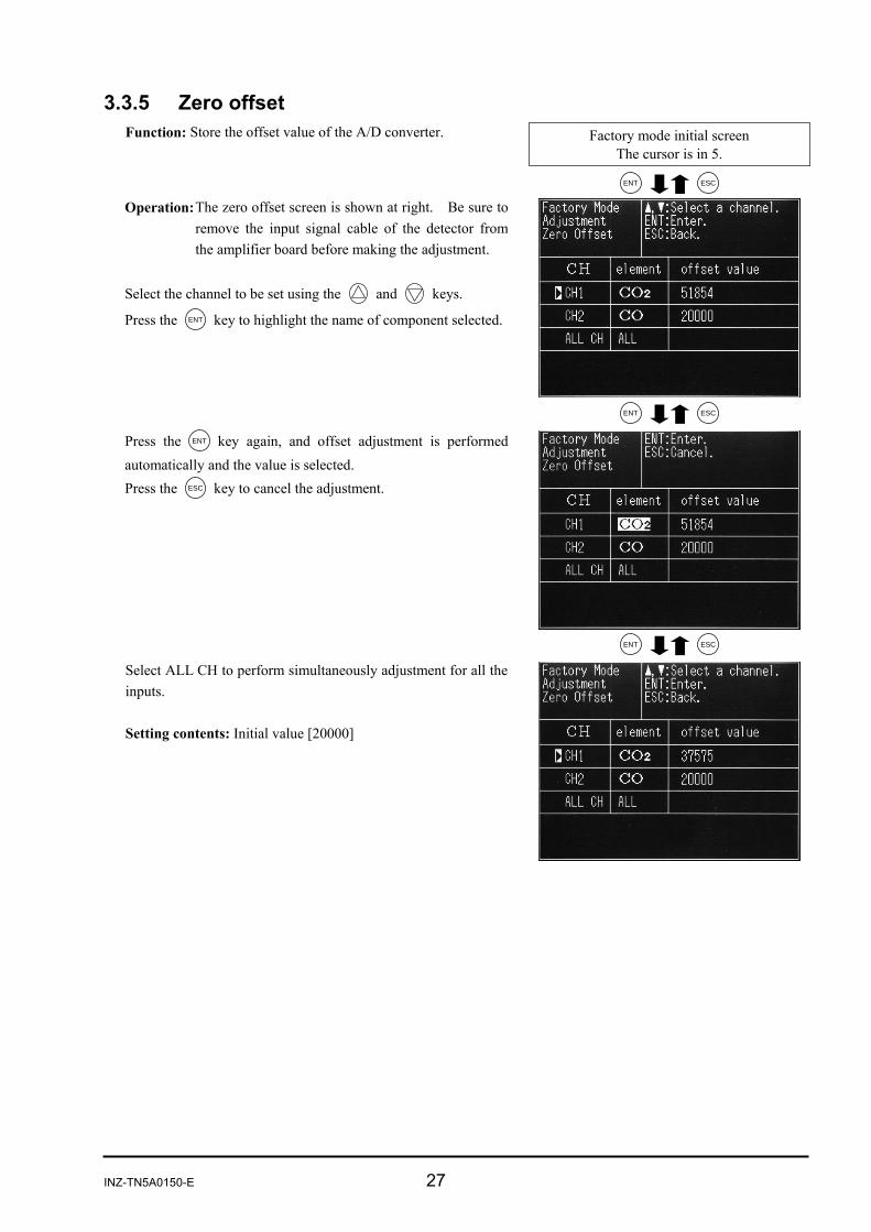
3.3.5 Zero offset
Factory mode initial screen The cursor is in 5.
Function: Store the offset value of the A/D converter.
ENT ESC Operation: The zero offset screen is shown at right. Be sure to
remove the input signal cable of the detector from the amplifier board before making the adjustment.
Select the channel to be set using the and keys.
Press the ENT key to highlight the name of component selected.
ENT ESC Press the ENT key again, and offset adjustment is performed automatically and the value is selected. Press the ESC key to cancel the adjustment.
ENT ESC Select ALL CH to perform simultaneously adjustment for all the
inputs. Setting contents: Initial value [20000]

28 INZ-TN5A0150-E
3.3.6 Linearizer
Factory mode initial screen The cursor is in 6.
Function: Set the linearize table calculated using the calibrationcurve measurement data. This allows linearity correction to be made. ENT ESC
Operation: The linearize table setting screen is shown at right. Select the CH to be set using the and keys.
Press the ENT key to enter the table setting screen.
ENT ESC Select the set point using the , and keys.
Press the ENT key to highlight the setting.
ENT ENT or ESC Move the digit using the key and make the setting for eachdigit. Change the setting using the and keys. Press the ENT key to confirm the setting.
Press the ESC key to cancel the setting. Setting contents: The linearization function uses 16 broken line
approximation for calculation. Enter the value of each break point calculated from thecalibration curve for setting.
X and Y represent the X and Y axes, and points 1 to 16correspond to each break point. The first break point and the 16th break point correspond to thezero and values of the maximum range, “00000” and “20000”respectively.
Initial value: In the order of correction points from 1 to16 both for X and Y axes [0, 800, 1600, 2400, 3200, 4000, 5000, 6000, 7000, 8000, 10000, 12000, 14000, 16000, 18000, 20000] (Non-linear state)

INZ-TN5A0150-E 29
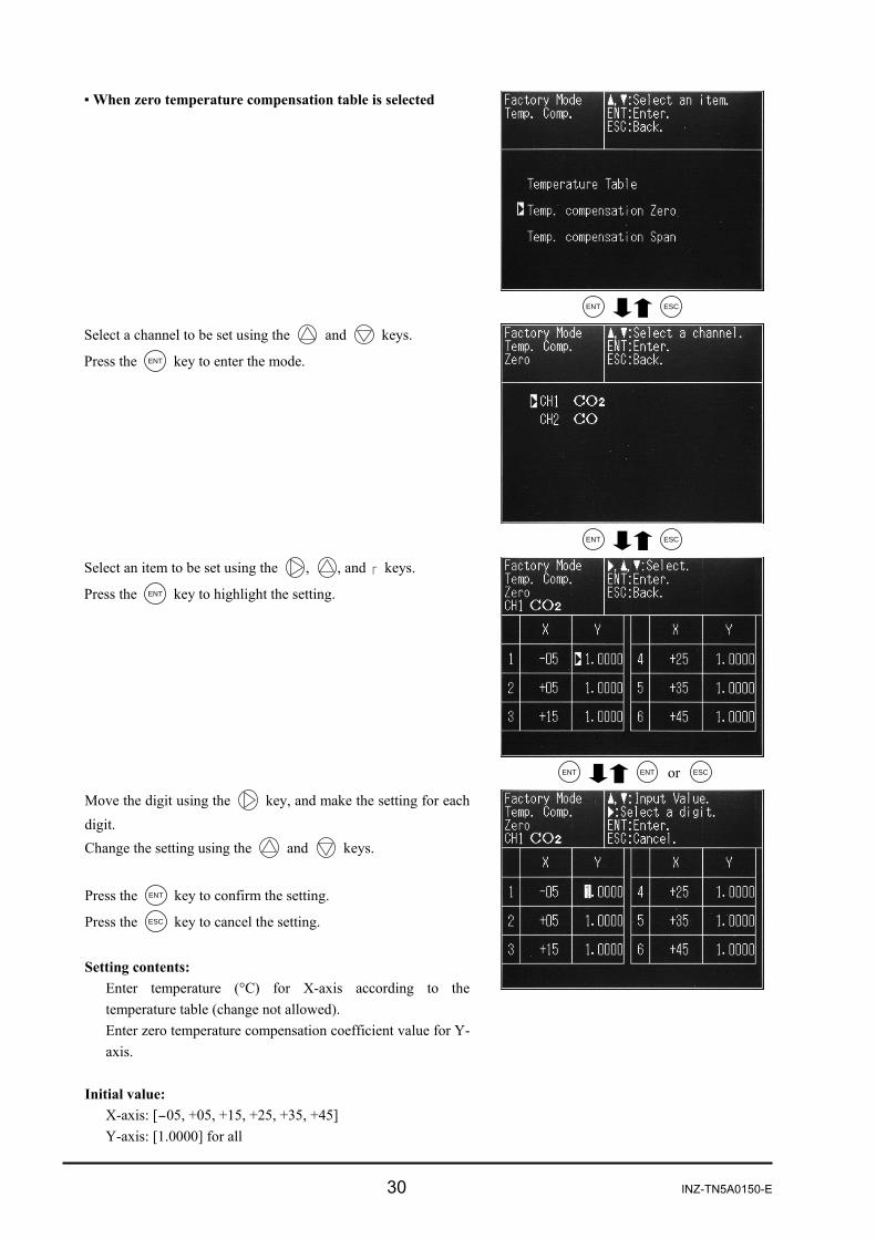
3.3.7 Temperature compensation
Factory mode initial screen The cursor is in 7.
ENT ESC
ENT ESC
ENT ENT or ESC
Function: Set the temperature compensation coefficient and temperature counts calculated from the temperature characteristic test data.
This allows temperature compensation to be performed.
Operation: The temperature compensation setting screen is shown at right.
Select the item to be set using the and keys.
Press the ENT key to enter the mode. Temperature table:
Set the count of the temperature sensor for each temperature.Zero temperature compensation table:
Set the temperature compensation coefficient at zero point for each temperature.
Span temperature compensation table: Set the temperature compensation coefficient at span point for each temperature.
When temperature compensation table is selected Select the count using the , , and keys.
Press the ENT key to highlight the setting.
Move the digit using the key, and make the setting for each digit. Change the setting using the and keys. Press the ENT key to confirm the setting.
Press the ESC key to cancel the setting. Setting contents:
The X-axis represents temperature (°C). The Y-axis represents temperature count (A/D conversion value of the temperature sensor).
Initial value: X-axis: In the order from 1 to 6 [-05, +05, +15, +25, +35, +45] Y-axis: In the order from 1 to 6 [15940, 16750, 17560, 18370, 19145, 19920]
30 INZ-TN5A0150-E
When zero temperature compensation table is selected
ENT ESC Select a channel to be set using the and keys.
Press the ENT key to enter the mode.
ENT ESC Select an item to be set using the , , and keys.
Press the ENT key to highlight the setting.
ENT ENT or ESC Move the digit using the key, and make the setting for each
digit. Change the setting using the and keys. Press the ENT key to confirm the setting.
Press the ESC key to cancel the setting. Setting contents:
Enter temperature (°C) for X-axis according to the temperature table (change not allowed). Enter zero temperature compensation coefficient value for Y-axis.
Initial value:
X-axis: [-05, +05, +15, +25, +35, +45] Y-axis: [1.0000] for all

INZ-TN5A0150-E 31
When span temperature compensation table is selected
ENT ESC Select a channel to be set using the and keys.
Press the ENT key to enter the mode.
ENT ESC Select an item to be set using the , , and keys.
Press the ENT key to highlight the setting.
ENT ENT or ESC Move the digit using the key, and make the setting for each
digit. Change the setting using the and keys. Press the ENT key to confirm the setting.
Press the ESC to cancel the setting. Setting contents:
Enter span temperature compensation coefficient. Initial value:
X-axis: [-05, +05, +15, +25, +35, +45] Y-axis: [1.0000] for all
32 INZ-TN5A0150-E
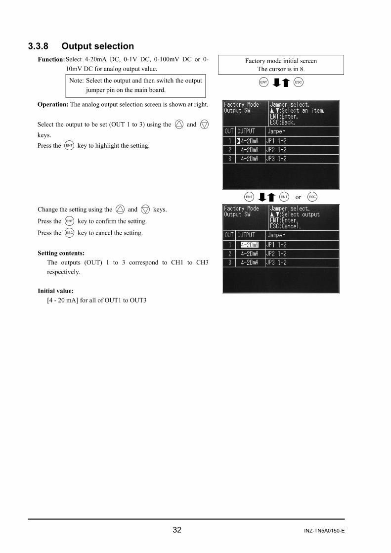
3.3.8 Output selection Factory mode initial screen
The cursor is in 8.
ENT ESC
Function: Select 4-20mA DC, 0-1V DC, 0-100mV DC or 0-10mV DC for analog output value.
Note: Select the output and then switch the output jumper pin on the main board.
Operation: The analog output selection screen is shown at right. Select the output to be set (OUT 1 to 3) using the and keys. Press the ENT key to highlight the setting.
ENT ENT or ESC Change the setting using the and keys.
Press the ENT key to confirm the setting.
Press the ESC key to cancel the setting. Setting contents:
The outputs (OUT) 1 to 3 correspond to CH1 to CH3respectively.
Initial value:
[4 - 20 mA] for all of OUT1 to OUT3

INZ-TN5A0150-E 33
3.3.9 Output adjustment
Factory mode initial screen The cursor is in 9.
Function: Adjust the zero point and span point of the analogoutput.
ENT ESC
Operation: The Analog Output Adjustment screen is as shown at right.
Select the output to be adjusted (OUT 1 to 3) using the ,
, and keys, and connect the digital voltmeter to the outputterminal. * See “3.3.8 Output selection” for the correspondence betweenOUT No. and output. Press the ENT key to highlight the setting.
ENT ENT or ESC
Adjust the value using the , and keys, seeing the value on the digital voltmeter.
Adjust the output as follows: When 4-20mA DC, zero: 4 mA ± 0.05 mA DC Span: 20 mA ± 0.05 mA DC When 0-1V DC, zero: 0 V ± 0.005V DC Span: 1 V ± 0.005 V DC When 0-100mV DC, zero: 0 mV ± 0.5mV DC Span: 100 mV ± 0.5 mV DC When 0-10mV DC, zero: 0 mV ± 0.05mV DC Span: 10mV ± 0.05 mV DC Press the ENT key to confirm the setting.
Press the ESC key to cancel the setting. Setting contents:
The outputs (OUT) 1 to 3 correspond to CH1 to CH3respectively. The settings are digital values transmitted to the D/Aconverter.
Initial value: OUT1 to 3
Current output: [Zero = 0800] [Span = 3850] Voltage output: [Zero = 0540] [Span = 3440]

34 INZ-TN5A0150-E
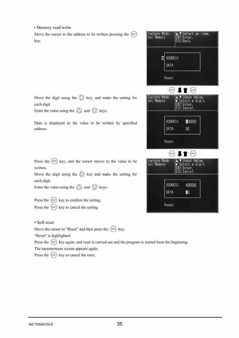
3.3.10 Memory rewrite
Factory mode initial screen The cursor is in 10.
ENT ESC
Function: Directly read and write EEPROM and RAM data to the specified address.
Perform soft reset.
Note: An address map is required to write values here. Do not perform memory rewrite, because malfunction results if improper value is written.
Operation: The set memory screen is shown at right.
INZ-TN5A0150-E 35
Memory read/write Move the cursor to the address to be written pressing the ENT
key.
ENT ESC Move the digit using the key, and make the setting for each digit. Enter the value using the and keys. Data is displayed as the value to be written by specified address.
ENT ESC Press the ENT key, and the cursor moves to the value to be written. Move the digit using the key and make the setting for each digit. Enter the value using the and keys. Press the ENT key to confirm the setting.
Press the ESC key to cancel the setting.
Soft reset Move the cursor to “Reset” and then press the ENT key. “Reset” is highlighted. Press the ENT key again, and reset is carried out and the program is started from the beginning. The measurement screen appears again. Press the ESC key to cancel the reset.
36 INZ-TN5A0150-E
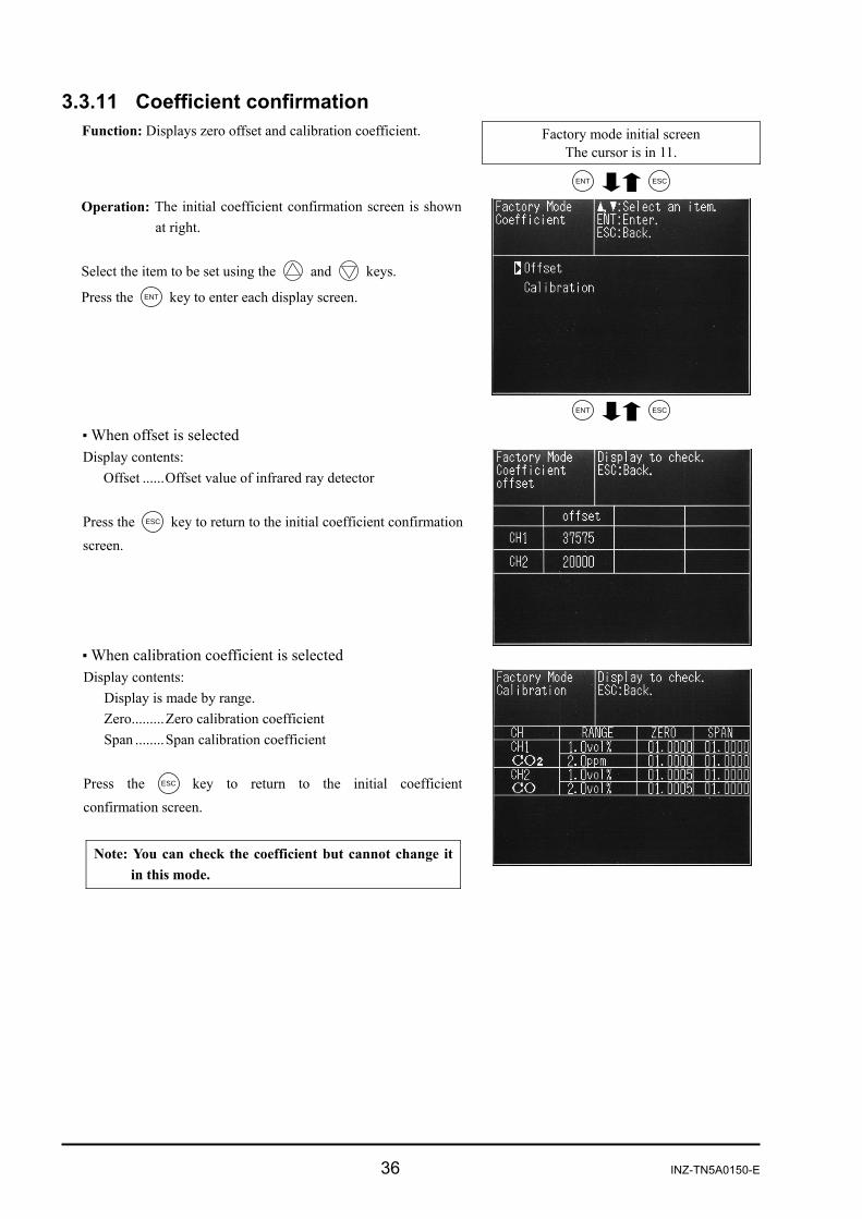
3.3.11 Coefficient confirmation
Factory mode initial screen The cursor is in 11.
Function: Displays zero offset and calibration coefficient.
ENT ESC Operation: The initial coefficient confirmation screen is shown
at right. Select the item to be set using the and keys.
Press the ENT key to enter each display screen.
ENT ESC When offset is selected Display contents:
Offset ......Offset value of infrared ray detector Press the ESC key to return to the initial coefficient confirmationscreen.
When calibration coefficient is selected Display contents:
Display is made by range. Zero.........Zero calibration coefficient Span ........Span calibration coefficient
Press the ESC key to return to the initial coefficient confirmation screen.
Note: You can check the coefficient but cannot change it in this mode.
INZ-TN5A0150-E 37
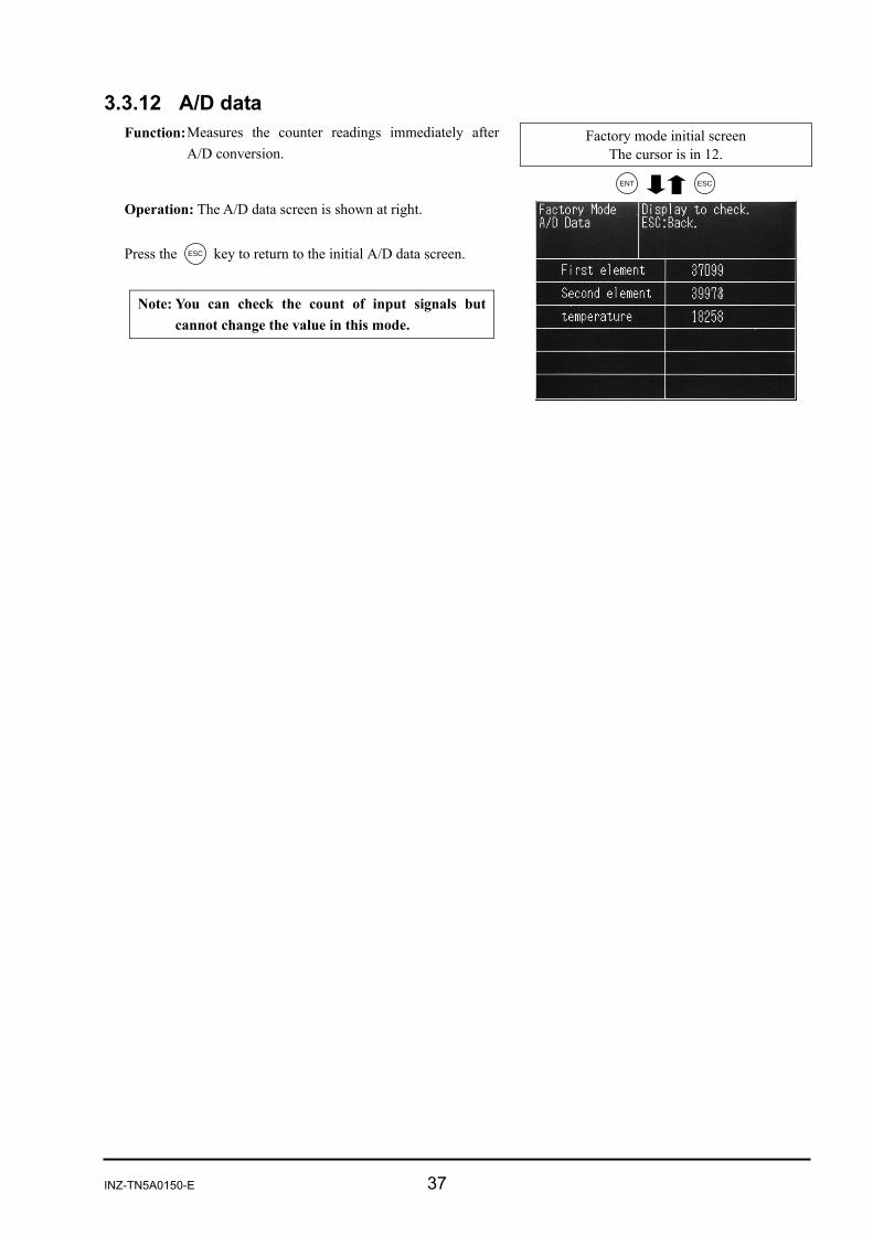
3.3.12 A/D data Function: Measures the counter readings immediately after
A/D conversion.
Factory mode initial screen The cursor is in 12.
ENT ESC Operation: The A/D data screen is shown at right. Press the ESC key to return to the initial A/D data screen.
Note: You can check the count of input signals but cannot change the value in this mode.
38 INZ-TN5A0150-E
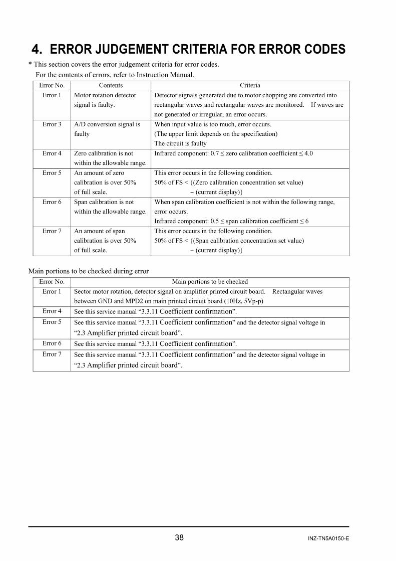
4. ERROR JUDGEMENT CRITERIA FOR ERROR CODES * This section covers the error judgement criteria for error codes.
For the contents of errors, refer to Instruction Manual. Error No. Contents Criteria Error 1 Motor rotation detector
signal is faulty. Detector signals generated due to motor chopping are converted into rectangular waves and rectangular waves are monitored. If waves are not generated or irregular, an error occurs.
Error 3 A/D conversion signal is faulty
When input value is too much, error occurs. (The upper limit depends on the specification) The circuit is faulty
Error 4 Zero calibration is not within the allowable range.
Infrared component: 0.7 ≤ zero calibration coefficient ≤ 4.0
Error 5 An amount of zero calibration is over 50% of full scale.
This error occurs in the following condition. 50% of FS < (Zero calibration concentration set value) - (current display)
Error 6 Span calibration is not within the allowable range.
When span calibration coefficient is not within the following range, error occurs. Infrared component: 0.5 ≤ span calibration coefficient ≤ 6
Error 7 An amount of span calibration is over 50% of full scale.
This error occurs in the following condition. 50% of FS < (Span calibration concentration set value) - (current display)
Main portions to be checked during error
Error No. Main portions to be checked Error 1 Sector motor rotation, detector signal on amplifier printed circuit board. Rectangular waves
between GND and MPD2 on main printed circuit board (10Hz, 5Vp-p) Error 4 See this service manual “3.3.11 Coefficient confirmation”. Error 5 See this service manual “3.3.11 Coefficient confirmation” and the detector signal voltage in
“2.3 Amplifier printed circuit board”. Error 6 See this service manual “3.3.11 Coefficient confirmation”. Error 7 See this service manual “3.3.11 Coefficient confirmation” and the detector signal voltage in
“2.3 Amplifier printed circuit board”.

INZ-TN5A0150-E 39
5. MEASURING PRINCIPLE DIAGRAM
Infrared ray type measuring principle diagram (CO2, CO, and CH4)
Output
Display
Signal processcalculation unit
Preamplifier
Mass-flow sensor
Detector
Rear expansion room
Front expansion roomInfrared raylight source
Motor Measuring cellChopper
Gas outletGas inlet
40 INZ-TN5A0150-E
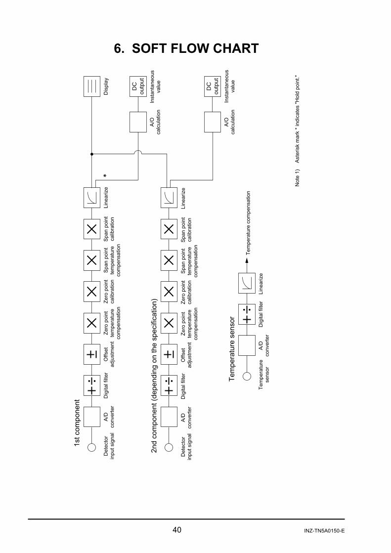
6. SOFT FLOW CHART
DC
outp
ut
!
"
#
DC
outp
ut
#
$
"%
&
&
'
()
*(
INZ-TN5A0150-E 41
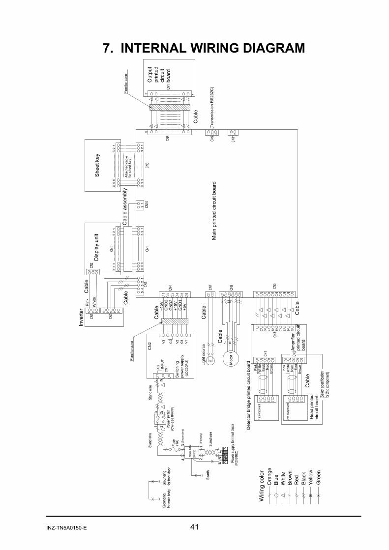
7. INTERNAL WIRING DIAGRAM
!
"
#$%
&%
'(
#
)
& * ( '+
,-.
)
/+(%
+
(
0+
+'
1
1
1(
2/
3&1
2/
2
+
3&1
2/
#!!
+$% 44
!
+
&
('
&( '
+
+
(
+
(
5
5
(
/
+*
&
+&
+
+
(
'( & *
!
2
6&1
&
0"
!
!
&7
"
"!
7
8!!
!
/!)!!
!
& *'
&
+
'(
& *'
9!
!
$
9!
!
$
(+
'
& 5 * 7
+(
'(
& 5 * 7 '(+7
+(
(
5
0!
"
&
+
(
+5
+
:
!
!
.9 (+
0
5
(
+
!
2!)
"!
2!)
""!
+
,;
+
+
+
+
+
+
+
+
$
$)
9!
<
$
:)
2

42 INZ-TN5A0150-E
8. INTERNAL PIPING
Name Pipe diameter Drawing No./ Material code Quantity Symbol Toaron φ9/φ5 TK727528P1 450mm Hose band φ8 TK7M9363P1 2 pcs. 0

INZ-TN5A0150-E 43
9. PRINTED CIRCUIT BOARD DIAGRAM 9.1 Amplifier printed circuit board
N15DV2
JP2
VR4
JP1
TP2 P15
VR1
DV1
VR2
GNDTP6SG2SG1VR3
9.2 Output printed circuit board
44 INZ-TN5A0150-E
9.3 Main printed circuit board GND
A15N
VDD
N12VCC VG A15PVD TP4