COMPACT STRETCHER SERIE TG -241
36
C/ Narcís Monturiol, 34 08192 Sant Quirze del Vallès BARCELONA TEL. 93 714-49-24 [email protected] www.kartsana.com INSTRUCTION MANUAL COMPACT STRETCHER SERIE TG-241 Models TG-241-S, TG-241-M, TG-241-L Please read the instruction manual before usage and keep them for future reference.
Transcript of COMPACT STRETCHER SERIE TG -241

C/ Narcís Monturiol, 34
08192 Sant Quirze del Vallès
BARCELONA
TEL. 93 714-49-24
www.kartsana.com
INSTRUCTION MANUAL
COMPACT STRETCHER SERIE TG-241
Models TG-241-S, TG-241-M, TG-241-L
Please read the instruction manual before usage and keep them for future reference.


OPERATION AND HANDLING OF THE
TG-241 SERIES
1 Rev.4 20-12-17
CONTENTS
1.- INTRODUCTION 3
1.1.- FOREWORD 3 1.2.- RESPONSIBILITY AND WARRANTY 3 1.3.- SPECIFICATIONS 3 1.4.- ATTENTION 4 1.5.- SUMMARY OF SAFETY PRECAUTIONS 4
2.- INSTRUCTIONS MANUAL 6
2.1.- TECHNICAL SPECIFICATIONS 6 2.1.1.- TECHNICAL SPECIFICATIONS TG-241-S / M / L 6 2.2.- OPERATING AND HANDLING THE STRETCHER 7 2.2.1.- REMOVABLE CUFFS 7 2.2.2.- ADJUSTABLE RECLINING HEAD 7 2.2.3- ADJUSTABLE LEG REST 8 2.2.4.- SAFETY RAIL 8 2.2.5.- INTRAVENOUS DRIP STAND 9 2.2.6.- METHOD FOR FASTENING THE SAFETY BELTS ON THE PATIENT’S HEAD AND FEET 10 2.2.7.- METHOD FOR FASTENING THE SAFETY BELT ON THE PATIENT’S 10 2.2.8.- DISMANTLING-ASSEMBLING THE STRETCHER SAFETY BELTS 11 2.2.9.- CONTROL FOR OPERATING THE STRETCHER LEGS 13 2.2.10.- INTERMEDIATE POSITIONS OF THE STRETCHER 14 2.2.11.- BRAKE LEVER 17 2.2.12.- LOCK/UNLOCK WHEELS 17 2.2.13.- MOUNTING THE STRETCHER ON THE AMBULANCE STRETCHER HOLDER 18
3.- DESINFECTION 19
4.- MAINTENANCE 19
5.- EXPLODED VIEWS 20
5.1.- TG-241-S 20 5.2.- TG-241-M 24 5.3.- TG-241-L 28

OPERATION AND HANDLING OF THE
TG-241 SERIES
2 Rev.4 20-12-17

OPERATION AND HANDLING OF THE
TG-241 SERIES
3 Rev.4 20-12-17
1. - INTRODUCTION
1.1.- Foreword
TG-241 series is specially designed for the rescue and transportations of patients.
TG-241 series is and has been test in accordance with the UNE-EN 1865 and UNE-EN 1789 standards.
All the information regarding treatment, disinfection and maintenance is indicated, taking into consideration our current experience and know-how.
Certain technical modifications to the stretcher have been placed under reserve with the purpose of making improvements to the product.
We reserve the right to change the specifications of the stretcher to improve the products.
1.2.- Responsibility and warranty
The stretcher must be checked at the time of its delivery to the assistance organisation. All its functions must be explained in great detail. The assistance organisation must take charge of teaching all its employees how to use it correctly.
The product has a warranty of 24 months from the date of delivery to the end user.
The warranty will not cover the fault if that fault is due to incorrect installation, mistreatment or improper use of the stretcher. All repairs must be made by a technical service authorised by Kartsana or its respective representative.
The manufacture will not be responsible for any anomaly caused to the stretcher due to using any products other than original Kartsana products.
1.3.- Specifications
MODELS TG-241-S TG-241-M TG-241-L
Maximum load 250 Kg* 250 Kg* 250 Kg*
Standards
UNE-EN-1865-1 EN-1789+A1
UNE-EN-1865-1 EN-1789+A1
UNE-EN-1865-1 EN-1789+A1
Total length (non-extended / extended) 1951/ 2250 mm 1951/ 2250 mm 1951/ 2250 mm
Total Width 570 mm 570 mm 570 mm
Loading Height 519 mm 574 mm 624 mm
Weight 37 Kg 37 Kg 37,5 Kg
Minimum operators required for an occupied / unoccupied stretcher
2 / 1 2 / 1 2 / 1
Compatible fixation systems
R-419 / R-450 -S / R-800 y R-900
R-419 / R-450 -S / R-800 y R-900
R-419 / R-450 -S / R-800 y R-900
*Stretcher not valid for bariatric or pediatric transports.

OPERATION AND HANDLING OF THE
TG-241 SERIES
4 Rev.4 20-12-17
1.4.- Attention
Through this sign, information is furnished on important safety measures for the
correct use of the stretcher, in order to prevent accidents. The warnings alerts the reader about a situation which, if not avoided, could result in death or serious injury.
The cautions alerts the reader of a potentially hazardous situation which, if not avoided, may result in minor or moderate injury to the user or patient or damage to the equipment or other property. This includes special care necessary for the safe and effective use of the device and the care necessary to avoid damage to a device that may occur as a result of use or misuse.
1.5.- Summary of safety precautions
Carefully read and strictly follow the warnings and cautions listed on these pages. Service only by qualified personnel.
WARNINGS:
- Improper usage of the stretcher can cause injury to the patient or operator. Operate the stretcher only as described in this manual.
- Do not modify the stretcher or any components of the stretcher. Modifying the product can cause unpredictable operation resulting in injury to the patient or operator. Modifying the product also voids its warranty.
- Any emergency vehicle to be used with this stretcher must have the compatible fixation system installed.
- Have the vehicle safety rail compatible installed by a certified mechanic. Improper rail installation can cause injury to the patient or operator and/or damage to the stretcher. Verify that the stretcher legs lock into the load position before without contact with the fender of the vehicle. Failure to properly lock the stretcher height into position can cause injury to the patient or operator and/or damage to the stretcher
- Practice changing height positions and loading the stretcher until operation of the product is fully understood. Improper use can cause injury.
-Do not allow untrained assistants to assist in the operation of the stretcher. Untrained technicians/assistants can cause injury to the patient or themselves.
- Grasping the stretcher improperly can cause injury. Keep hands, fingers and feet away from moving parts. To avoid injury, use extreme caution when placing your hands and feet near the base tubes while raising and lowering the stretcher.
- Always use all restraint straps to secure the patient on the stretcher. An unrestrained patient may fall from the stretcher and be injured.
- Never leave a patient unattended on the stretcher or injury could result. Hold the stretcher securely while a patient is on the product.
- Side rails are not intended to serve as a patient restraint device.
- High obstacles such as curbing, steps or rough terrain can cause the stretcher to tip, possibly causing injury to the patient or operator.
- TG-241 series is designed to be compatible with Kartsana models R-419 / R-450 -S / R-700 y R-800, and is operator responsibility that these products work together.
- Two operators must be present when the stretcher is occupied.
- Operators must be able to lift the total weight of the patient, stretcher and any items on the stretcher.
- Never install or use a wheel lock on a stretcher with excessively worn wheels. Installing or using a wheel lock on a wheel with less than a 200mm diameter could compromise the holding ability of the wheel lock, possibly resulting in injury to the patient or operator and/or damage to the stretcher or other equipment.

OPERATION AND HANDLING OF THE
TG-241 SERIES
5 Rev.4 20-12-17
- When cleaning, use any appropriate personal safety equipment (goggles, respirator, etc.) to avoid the risk of inhaling contagion.
- Some cleaning products are corrosive in nature and may cause damage to the product if used improperly. If the products described above are used to clean Kartsana equipment, measures must be taken to ensure the stretchers are wiped with clean water and thoroughly dried following cleaning. Failure to properly rinse and dry the stretchers will leave a corrosive residue on the surface of the stretchers, possibly causing premature corrosion of critical components.
- Failure to properly clean or dispose of contaminated mattress or other stretcher components will increase the risk of blood borne pathogens and may cause injury to the patient or operator.
CAUTIONS:
- Changes or modifications to the unit not expressly approved by Kartsana could void the user’s authority to operate the
system.
- Installation of the safety hook should be done by a certified mechanic familiar with ambulance vehicle construction. Consult the vehicle manufacturer before installing the safety hook and be sure that the installation of the safety hook does not damage or interfere with the brake lines, oxygen lines, fuel lines, fuel tank or electrical wiring of the vehicle.
- Before operating the stretcher, clear any obstacles that may interfere and cause injury to the operator or patient.
- When unloading the stretcher from the patient compartment, ensure that the caster wheels are safely set on the ground or damage to the product may occur.
- Wheel lock(s) are only intended to help prevent the stretcher from rolling while unattended and to aid in patient transfer. A wheel lock may not provide sufficient resistance on all surfaces or under loads.
- Ensure that the restraints are not entangled in the base frame when raising and lowering the stretcher.
- Do not store items under the stretcher mattress. Storing items under the mattress can interfere with the operation of the stretcher.
- Do not steam clean or ultrasonically clean the unit.
- Maximum water temperature should not exceed 80°C.
- Allow stretcher to air dry.
- Towel dry all casters and interface points.
- Failure to comply with these instructions may invalidate any/all warranties.
- Improper maintenance can cause injury or damage to the product. Maintain the stretcher as described in this manual. Use only Kartsana approved parts and maintenance procedures. Using unapproved parts and procedures could cause unpredictable operation and/or injury and will void the product warranty
- Failure to use authorized parts, lubricants, etc. could cause damage to the stretcher and will void the warranty of the product.
.
NOTES:
- Loose items or debris on the patient compartment floor can interfere with the operation of the safety hook and stretcher fastener. Keep the patient compartment floor clear
- This manual should be considered a permanent part of the stretcher and should remain with the product even if the stretcher is subsequently sold.
- Kartsana continually seeks advancements in product design and quality. Therefore, while this manual contains the most current product information available at the time of printing, there may be minor discrepancies between your stretcher and this manual
- Kartsana recommends that, prior to installation, the certified mechanic plan the placement of the safety hook in the rear of the vehicle.

OPERATION AND HANDLING OF THE
TG-241 SERIES
6 Rev.4 20-12-17
2.- INSTRUCTIONS MANUAL
TG-241 series is adapted for mounting on Kartsana rails R-419, R-450-S inox, R-700 and R-800
To reduce the risk of injuries to the patient and accompanying persons in the event of an accident, it is advisable to avoid sharp edges and projecting parts inside the ambulance, paying special attention to the areas nearest to the stretcher.
Make sure that no damage is caused to the areas containing the stretcher mechanisms, to prevent them from malfunctioning.
2.1.- Technical specifications
2.1.1.- Technical specifications TG-241-S / M / L
Measurements (in mm):
MODEL * **
TG-241-S 519 798
TG-241-M 574 854
TG-241-L 624 904

OPERATION AND HANDLING OF THE
TG-241 SERIES
7 Rev.4 20-12-17
2.2.- Operating and handling the stretcher
To prevent injuries to limbs and other body parts, make sure they are not within the range of the moving parts of the stretcher.
Clarification: The front part of the stretcher corresponds to the head part.
2.2.1.- Removable cuffs
Press the button at the top of the cuff, and then pull it to lengthen the cuff, as far as it will go.
To return the cuff to its original position, press the top button again and push it as far as it will go in the original position
2.2.2.- Adjustable reclining head
Apply the lever below the head and move it to the required position. Then release the lever so that the head is locked in the required position.
The top adhesive on the part of the stretcher shown in the drawing on the
left indicates how to manipulate the cuff in order to extend it.
Top button
Head lever
Head

OPERATION AND HANDLING OF THE
TG-241 SERIES
8 Rev.4 20-12-17
2.2.3- Adjustable leg rest
- Button for adjusting the leg inclination.
The required inclination of the leg rest can be obtained by pressing button A and moving the leg rest manually. Once the correct inclination has been reached, release button A to automatically lock the leg rest.
2.2.4.- Safety rail
The safety rail has a red bar that locks the rail into place. To lower the rail, just press the bar as shown in the figure below. To lock it in the safety position again, move it to that position manually, and it will automatically lock into place.
A
The adhesive on the part of the stretcher shown in the drawing
on the left indicates the red button that must be pressed to adjust the position of the legs.
Leg rest
A
Red bar
Safety rail

OPERATION AND HANDLING OF THE
TG-241 SERIES
9 Rev.4 20-12-17
2.2.5.- Intravenous drip stand
The stretcher comes with a drip holder located on the left hand side.
With the “A” knob we can loosen and tighten the assembly where and when it is convenient. Unscrewing the knob “B” we remove the IV drip stand to the vertical position perpendicular to the stretcher, then we twist the knob again.
The length of said drip pole may be lengthened or shortened pressing a small positioner located on the inner side, raising the hook until the upper position is reached.
The maximum load allowed
for the drip pole is 6 Kg.
The maximum weight is indicated on the drip rod by an adhesive like the one shown above.
A
B

OPERATION AND HANDLING OF THE
TG-241 SERIES
10 Rev.4 20-12-17
2.2.6.- Method for fastening the safety belts on the patient’s head and feet
Place the clasps (C) in the position shown in the figure above. Pass the male part of the buckle (D) between the openings (C) until it is inserted into the female part B. Once the assembly is anchored in place, centre and tauten the assembly, adjusting the tension of the belt at ends A and/or E.
NOTE: The foot belt is not fitted with the C openings.
2.2.7.- Method for fastening the safety belt on the patient’s
It is advisable for this belt to be attached to the stretcher to ensure the complete safety of the patients and guarantee compliance with the UNE-EN 1865 standard test that is performed.
Put the female part of the buckle A and male part B in the position shown in the figure below and insert the latter into the slot in the former. Once the assembly is firmly secured, centre and tauten it, adjusting the tension of the belt at end C.
It is advisable to ensure that while the patient is on the stretcher, he/she is secured at all times by the safety belts.

OPERATION AND HANDLING OF THE
TG-241 SERIES
11 Rev.4 20-12-17
2.2.8.- Dismantling-assembling the stretcher safety belts
Anchoring with a knot
To dismantle the belts, pass the belt through the slot in the buckle as shown in the following figure. To assembly it, just follow the same process but in reverse order.
The lateral belts must be fixed on the lateral profiles of the stretcher with a knot also.

OPERATION AND HANDLING OF THE
TG-241 SERIES
12 Rev.4 20-12-17
2.2.8.1.- Position of the belts
2.2.8.1.1. - Lateral belts
The belts are positioned at the approximate distances shown in the figure below:
2.2.8.1.2.- Head belts
The belts must be passed through the holes in the head rest part and secured on the crosspiece of the panel with a knot.
Belts
OPERATION AND HANDLING OF THE
TG-241 SERIES
13 Rev.4 20-12-17
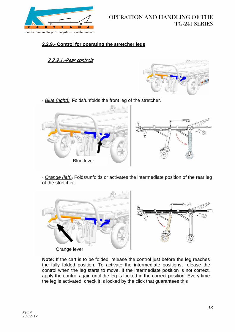
2.2.9.- Control for operating the stretcher legs
2.2.9.1.-Rear controls
· Blue (right): Folds/unfolds the front leg of the stretcher.
· Orange (left): Folds/unfolds or activates the intermediate position of the rear leg of the stretcher.
Note: If the cart is to be folded, release the control just before the leg reaches the fully folded position. To activate the intermediate positions, release the control when the leg starts to move. If the intermediate position is not correct, apply the control again until the leg is locked in the correct position. Every time the leg is activated, check it is locked by the click that guarantees this
Blue lever
Palanca naranja Orange lever

OPERATION AND HANDLING OF THE
TG-241 SERIES
14 Rev.4 20-12-17
2.2.9.2.- Lever front leg control
It activates the intermediate positions of the front leg of the stretcher (the starting point is the unfolded position).
Note: To return the leg to its original unfolded position, activate the front control and then raise that part of the stretcher manually so that the leg returns automatically. Just before the leg reaches the original unfolded position, release the control so that when the leg reaches that position, the click can be heard, indicating the leg is locked and thereby ensuring it is fixed in the original unfolded position.
2.2.10.- Intermediate positions of the stretcher
The stretcher has three kind of intermediate positions at different heights from the ground, depending on each need.
To ensure the safe treatment of the patient, the intermediate position should always be activated by two people. In addition, the safety belts must be placed on the patient and the rails raised before activating the intermediate positions.
Intermediate position lever

OPERATION AND HANDLING OF THE
TG-241 SERIES
15 Rev.4 20-12-17
1st Intermediate position:
Hold the stretcher firmly with both hands to prevent it from making dangerous movements.
Then the stretcher can also be inclined on one part (front or rear) by activating the controls as described above.
To perform this manoeuvre, activate the brakes on the front wheels and place them in the position shown on the adhesive, before activating the red lever at the side.
The position is achieved by activating the intermediate position lever (red) located on the right-hand side of the stretcher. This releases the front legs up to a mechanical stop.
Then apply the rear control (orange) once until it reaches the first position.
To return to the unfolded leg position, lift the stretcher slightly and raise ithe front legs using your foot.

OPERATION AND HANDLING OF THE
TG-241 SERIES
16 Rev.4 20-12-17
2nd Tredelenburg position
To perform this manoeuvre, activate the brakes on the front wheels and place them in the position shown on the adhesive, before activating the red lever at the side.
It is achieved by activating the intermediate position lever (red) located on the right-hand side of the stretcher. This releases the front legs up to a mechanical stop.
3rd Contratrendelenburg position It is positioned by activating the rear control (orange) once until it reaches the first position.
.

OPERATION AND HANDLING OF THE
TG-241 SERIES
17 Rev.4 20-12-17
2.2.11.- Brake lever
Activate the red lever with your foot to enable the brake to lock the rear wheels. That special brake blocks both the longitudinal and the rotating movement of the stretcher.
2.2.12.- Lock/Unlock wheels
- Rear wheels
The green bolt is used to block or unblock the rotation of the wheels, as shown in the following figure.
- Front wheels
The black trigger of the rear box allows lock/unlock the free movement of the front wheels.

OPERATION AND HANDLING OF THE
TG-241 SERIES
18 Rev.4 20-12-17
2.2.13.- Mounting the stretcher on the ambulance stretcher holder
Kartsana recommends using the Kartsana rails to secure the stretcher to the ambulance, since these have been specially designed for that purpose
Guide the stretcher to the ambulance platform and mount its front wheels (wheels with a diameter of 100 mm), on the stretcher holder, and if the platform has a Kartsana rail, place the front wheels outside the rails. Then activate the front wheels control to fold the front leg (blue control) and insert the stretcher into the stretcher holder up to the rear wheels. At this point, activate the rear wheel control (orange) to fold it.
After activating the orange control, part of the weight of the rear end of the stretcher must be supported, and so it will be necessary to hold it firmly with both hands.
Once the above process has been executed in full, the stretcher can be inserted completely into the stretcher holder, until it is locked in place at the front and rear. The Kartsana rails anchors the stretcher at the front by means of two anchoring points and one anchoring point at the rear (see the figures below). These anchoring points prevent the stretcher from overturning in the event of an accident. In the event of not using the Kartsana rails, it is advisable that the front part of the stretcher cart be anchored at the end of the bar marked 12 in the exploded diagram of the cart that is included in this manual
3rd Anchoring point
1st Anchoring point
2nd Anchoring point
OPERATION AND HANDLING OF THE
TG-241 SERIES
19 Rev.4 20-12-17
3.- DESINFECTION
When disinfecting the stretcher, use products that will not damage the surface of the materials and wipe with a cloth or something similar. If the surface to be disinfected is greased, regreased it after disinfecting it.
All disinfectants must be used in accordance with the manufacturer’s instructions.
The manufacturer will not be held responsible for any anomaly or damage caused by using a cleaning product that could damage the surface of the rail materials.
To ensure the hygiene and proper conservation of the product components, the manufacturer recommends that they be disinfected after each use.
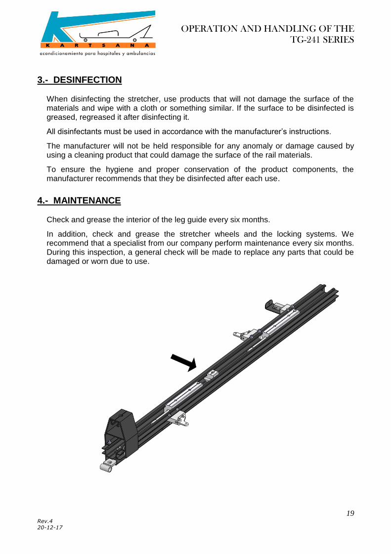
4.- MAINTENANCE
Check and grease the interior of the leg guide every six months.
In addition, check and grease the stretcher wheels and the locking systems. We recommend that a specialist from our company perform maintenance every six months. During this inspection, a general check will be made to replace any parts that could be damaged or worn due to use.

OPERATION AND HANDLING OF THE
TG-241 SERIES
20 Rev.4 20-12-17
5.- EXPLODED VIEWS
5.1.- TG-241-S

OPERATION AND HANDLING OF THE
TG-241 SERIES
21 Rev.4 20-12-17

OPERATION AND HANDLING OF THE
TG-241 SERIES
22 Rev.4 20-12-17

OPERATION AND HANDLING OF THE
TG-241 SERIES
23 Rev.4 20-12-17
14-0310-001 ETIQUETA PESO MAX. 250 Kg. SERIE 241
OPERATION AND HANDLING OF THE
TG-241 SERIES
24 Rev.4 20-12-17
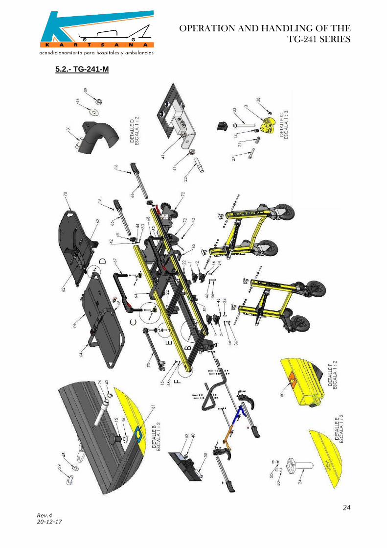
5.2.- TG-241-M

OPERATION AND HANDLING OF THE
TG-241 SERIES
25 Rev.4 20-12-17

OPERATION AND HANDLING OF THE
TG-241 SERIES
26 Rev.4 20-12-17

OPERATION AND HANDLING OF THE
TG-241 SERIES
27 Rev.4 20-12-17
14-0310-001 ETIQUETA PESO MAX. 250 Kg. SERIE 241

OPERATION AND HANDLING OF THE
TG-241 SERIES
28 Rev.4 20-12-17
5.3.- TG-241-L

OPERATION AND HANDLING OF THE
TG-241 SERIES
29 Rev.4 20-12-17

OPERATION AND HANDLING OF THE
TG-241 SERIES
30 Rev.4 20-12-17

OPERATION AND HANDLING OF THE
TG-241 SERIES
31 Rev.4 20-12-17
14-0310-001 ETIQUETA PESO MAX. 250 Kg. SERIE 241

OPERATION AND HANDLING OF THE
TG-241 SERIES
32 Rev.4 20-12-17
i. The pieces that his number reference starts in 13-xxxx-xxx will be elements of fixation.
ii. The pieces that his number reference starts in 50-xxxx-xxx will be welding sets and it will be supplied like an inseparable set, not at loose parts.
iii. The pieces that his number reference starts in 52-xxxx-xxx will be preassembly. In case of requesting some piece that belongs to a preassembly, contact with our technical services taking the reference of this preassembly and, if it’s necessary, the exploded view of preassembly may be provided.

OPERATION AND HANDLING OF THE
TG-241 SERIES
33 Rev.4 20-12-17

OPERATION AND HANDLING OF THE
TG-241 SERIES
34 Rev.4 20-12-17
Sistema de gestión
certificado