Compact FEL Based on Dielectric Wakefield Acceleration J.B. Rosenzweig UCLA Dept. of Physics and...
24
Compact FEL Based on Dielectric Wakefield Acceleration J.B. Rosenzweig UCLA Dept. of Physics and Astronomy Towards a 5 th Generation Light Source Celebration of Claudio Pellegrini Catalina Island — October 2,
-
Upload
morgan-cote -
Category
Documents
-
view
217 -
download
0
Transcript of Compact FEL Based on Dielectric Wakefield Acceleration J.B. Rosenzweig UCLA Dept. of Physics and...
Compact FEL Based on Dielectric Wakefield
Acceleration
J.B. RosenzweigUCLA Dept. of Physics and
Astronomy
Towards a 5th Generation Light Source Celebration of Claudio
PellegriniCatalina Island — October 2, 2010

FELs are Big Science
Size=$

Creating a compact FEL
High brightness beam Very low charge (pC) Attosecond pulse Few 10-8 norm. emittance
High field, short l undulator With HBB, large ,r short Lg
Lowers e- energy needed 2 GeV hard X-ray FEL
Hybrid cryo-undulator: Pr-based, SmCo sheath 9 mm l, up to 2.2 T
FEL w/1 pC driver at 2.1 GeV
J.B. Rosenzweig, et al., Nucl. Instruments Methods A, 593, 39 (2008)
F.H. O’Shea et al, PRSTAB 13, 070702 (2010)

Scaling the accelerator in size Lasers produce copious power (~J, >TW)
Scale in by 4 orders of magnitude challenges in beam dynamics
Reinvent resonant structure using dielectric GV/m fields possible, breakdown limited…
GV/m allows major reduction in size, cost of FEL, LC
To jump to GV/m, mm-THz may be better: Beam dynamics, breakdown scaling Need new power source…
Resonant dielectric laser-excited structure
(with HFSS simulated fields)

New paradigm for high field
acceleration: wakefields
Coherent radiation from bunched, v~c, e- beam Any slow-wave environment Powers exotic schemes: plasma, dielectrics
Resonant or non-resonant (short pulse) operation THz regime easily w/in reach
High average power beams can be produced Tens of MW, beats lasers… good for FEL, LC
Intense beams needed, synergy with many fields X-ray FEL, ICS X-ray source, intense THz
sources
Wakefields in dielectric tube

Schematic of wakefield-based collider
J. Rosenzweig, et al., Nucl. Instrum. Methods A 410 532 (1998). (concept borrowed from W. Gai…)
• Similar to original CLIC scheme • Study for plasma wakefield accelerator
• gg due to charge asymmetry in PWFA• Not a problem for DWA…
• FEL can avoid all this complexity, use one module
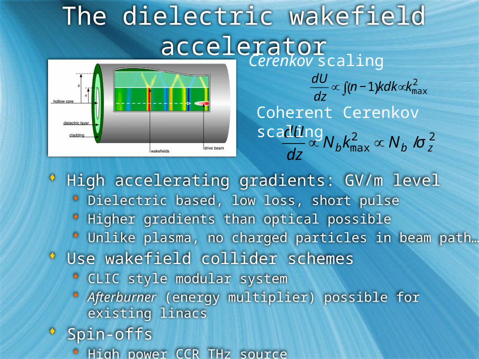
The dielectric wakefield accelerator
High accelerating gradients: GV/m level Dielectric based, low loss, short pulse Higher gradients than optical possible Unlike plasma, no charged particles in beam path…
Use wakefield collider schemes CLIC style modular system Afterburner (energy multiplier) possible for existing linacs
Spin-offs High power CCR THz source
€
dU
dz∝ n −1( )kdk ∝∫ kmax
2
€
dU
dz∝ N bkmax
2 ∝ N b /σ z2
Coherent Cerenkov scaling
Cerenkov scaling
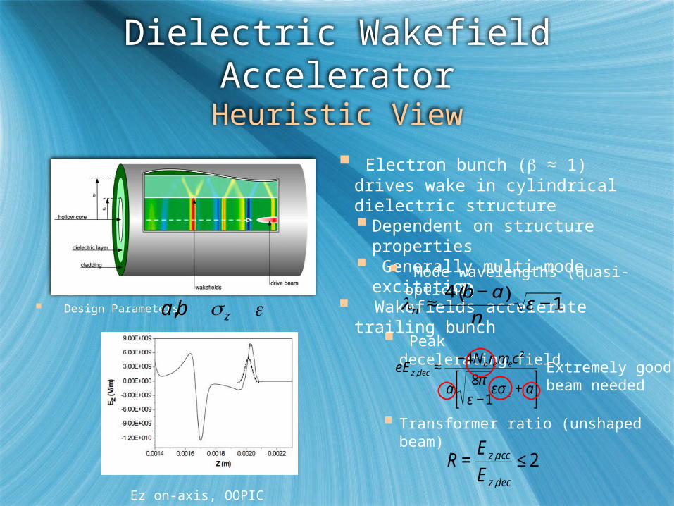
Dielectric Wakefield AcceleratorHeuristic View
Electron bunch ( ≈ 1) drives wake in cylindrical dielectric structure Dependent on structure properties Generally multi-mode excitation
Wakefields accelerate trailing bunch
Mode wavelengths (quasi-optical)
€
λn ≈4 b − a( )
nε −1
Peak decelerating field
€
eE z,dec ≈−4Nbremec
2
a8π
ε −1εσ z + a
⎡
⎣ ⎢
⎤
⎦ ⎥
Design Parameters
€
a,b
€
σ z
€
ε
Ez on-axis, OOPIC
*
Extremely good beam needed
€
R =E z,acc
E z,dec
≤ 2
Transformer ratio (unshaped beam)

T-481: Test-beam exploration of breakdown
threshold 1st ultra-short, high charge beams Beyond pioneering work at ANL…
Much shorter pulses, small radial size Higher gradients…
Leverage off E167 PWFA 48 hr FFTB run Excellent beam 3 nC, z ≥ 20 m, 28.5 GeV
Goal: breakdown studies Al-clad fused SiO2 fibers
ID 100/200 m, OD 325 m, L=1 cm
Avalanche v. tunneling ionization studies Prediction: beam can excite Ez ≤12GV/m
T-481 “octopus” chamber

Beam Observations, Analysis
View end of dielectric tube; frames sorted by increasing peak current
Multi-mode excitation – 100 fs, pulses separated by ps— gives better breakdown dynamics?
Breakdown determined by benchmarked OOPIC simulations
Breakdown limit:5.5 GV/m decel. Field(10 GV/m accel.?)
ultrashortbunch
longerbunch
Post mortem images

E169 Collaboration
H. Badakov, M. Berry, I. Blumenfeld, A. Cook, F.-J. Decker, M. Hogan, R. Ischebeck, R. Iverson, A. Kanareykin, N. Kirby, P.
Muggli, J.B. Rosenzweig, R. Siemann, M.C. Thompson, R. Tikhoplav, G. Travish, R. Yoderz, D. Walz
Department of Physics and Astronomy, University of California, Los AngelesStanford Linear Accelerator CenterUniversity of Southern California
Lawrence Livermore National LaboratoryzManhattanville CollegeEuclid TechLabs, LLC
Collaboration spokespersons
UCLA

E169 at FACET: overview
Research GV/m acceleration scheme in DWA Goals
Explore breakdown issues in detail Determine usable field envelope Coherent Cerenkov radiation measurements Varying tube dimensions
Impedance, group velocity dependences Explore alternate materials Explore alternate designs and cladding
Slab structure (permits higher Q, low wakes) Radial and longitudinal periodicity…
Observe acceleration
Awaits FACET construction Reapproval recently submitted Add AWA group to collaboration
Already explored At UCLA, BNL
Bragg fiber
CVD deposited diamond
Slab dielectric structure (like optical)
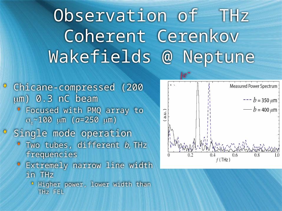
Observation of THz Coherent Cerenkov
Wakefields @ Neptune
Chicane-compressed (200 mm) 0.3 nC beam Focused with PMQ array to
sr~100 mm (a=250 mm)
Single mode operation Two tubes, different b, THz
frequencies Extremely narrow line width in
THz Higher power, lower width than THz
FEL

Transverse wakes and slab-symmetric structures
Slab symmetric structures: why? Can accelerate more
charge Mitigate transverse
wakes
Transverse wakes at FACET Observable BBU with >10
cm Simulated BBU @ FACET, Initial, 10.7 cm distribution (courtesy AWA group)
4 GV/m simulated wakes for FACET experiment
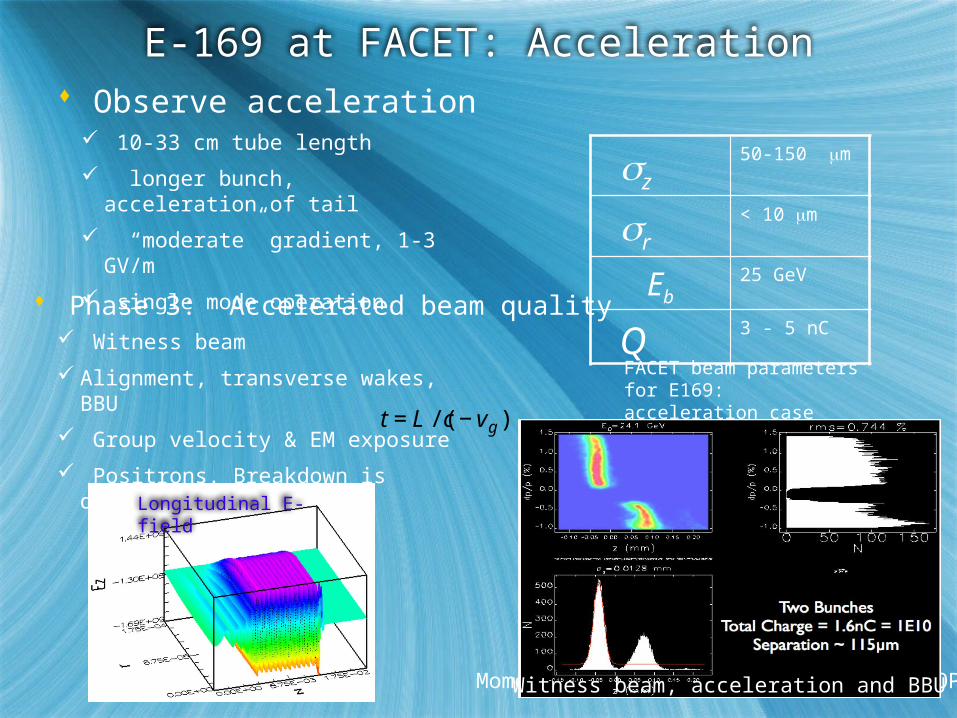
E-169 at FACET: Acceleration Observe acceleration
10-33 cm tube length
longer bunch, acceleration of tail
“moderate” gradient, 1-3 GV/m
single mode operation
z50-150 m
r< 10 m
Eb25 GeV
Q 3 - 5 nC Phase 3: Accelerated beam quality
Momentum distribution after 33 cm (OOPIC)
Witness beam
Alignment, transverse wakes, BBU
Group velocity & EM exposure
Positrons. Breakdown is different?
FACET beam parameters for E169: acceleration case
Longitudinal E-field
Witness beam, acceleration and BBU
€
t = L /(c − vg )

A High Transformer Scenario using Dielectric
Wakes How to reach high
energy with DWAs? Enhanced transformer
ratio with ramped beam Does this work with
multi-mode DWA? Scenario: 500-1000 MeV
ramped driver; 5-10 GeV X-ray FEL injector in <10 m
Symmetric beam R<2
Ramped beam R>>2

A FACET test for light source scenario
Beam parameters: Q=3 nC,
ramp L=2.5 mm,U=1 GeV Structure: a=100 mm, b=100 mm, e=3.8 Fundamental f=0.74 THz Performance: Ez>GV/m,
R=9-10 (10 GeV beam) Ramp achieved at UCLA.
Possible at ATF, FACET?
Longitudinal wakefields
Longitudinal phase spaceafter 1.3 m DWA (OOPIC)
R. J. England, J. B. Rosenzweig, and G. Travish, PRL 100, 214802 (2008)
Ramped beam using sextupole-correcteddogleg compression

Multipulse operation: control of group velocity
Multiple pulse beam-loaded operation in linear collider Needs low vg
Low Q, e beams shorter, smaller Can even replace large Q
driver
Use periodic DWA structure
in ~p-mode, resonant excitation
Accelerating beam Driving beam Example: SiO2/diamond structure
€
N ×

Standing wave wakes in periodic dielectric
structures
4 pulse train excitation, 2-l separation
Rms pulse length /4,l suppresses HOM

Initial multi-pulse experiment: uniform SiO2
DWA at BNL ATF Exploit Muggli pulse train slicing
technique 400 mm spacing, micro-Q=25 pC, sz=80
mm DWA dimensions: a=100 mm, b=150 mm

BNL multi-pulse experiments
Array of 1 cm tubes Si02, also diamond 325-660 mm l
Large aperture 490 mm case first Use PMQs later…
Operation of pulse train with both chirp signs Sextupole correction
used CTR autocorrelation
4-drive + witness in spectrometer
CTR autocorrelation and FFT

Recent results from BNL multi-pulse experiments
Single, multi- bunch wakes observed
Wakes without mask give fundamental resonant l ~490 mm, per prediction
Resonant wake excitation, CCR spectrum measured Excited with 190 mm
spacing (2nd harmonic) Misalignments yield ~l 300
mm, 1st deflecting mode
1st deflecting mode
Fundamental (@noise level)
2nd harmonic
CCR autocorrelation
Frequency spectrum

Towards GV/m: multiple pulse DWA experiment at
SPARC/X Uses laser comb
technique Bunch periodicity: 190 mm (0.63 ps) 0.5 of BNL case Scaled structure
125 pC/pulse @ 750 MeV
4 pulses + witness 1 GV/m, energy
doubling in <70 cm
>1.1 GV/m wakes in scaled DWA@SPARX

Honey, I shrunk the FEL (not quite yet…CP’s 80th)
FEL itself gets small with small Q, high brightness beams; innovative undulators Lower energy needed Ultimate limit in optical undulators?
Wakefields give very high field DWA gives a credible path Booster for hard X-ray FEL in few m Scaling to low Q synergistic, hard
Expect rapid experimental progress 1st ATF; then FACET, SPARC/X, etc.
TV/m simulated PWFAusing LCLS 20 pC beam