
Compact Disc: system aspectsand modulation - … Bound...Compact Disc: system aspectsand modulation...
9
.' Compact Disc: system aspects and modulation J. P. J. Heemskerk and K. A. Schouhamer lmmink Fig.!. The Compact Disc system, considered as a transmission system that brings sound from the studio into the living room. The transmission channel between the encoding system (COD) at the recording end and the decoding system (DECaD) in the player, 'transmits' the bit stream Bi to DECOD via the write laser, the master disc (MD), the disc manufacture, the disc (D) in the player and the optical pick-up; in the ideal case Bo is the same as Bi. The bits of Bo, as well as the clock signal (Cl) for further digital operations, have to be detected from the output signalof the pick- up unit at Q. Philips tech. Rev. 40, 157-164, 1982, No. 6 In this article we shall deal in more detail with the various factors that had to be weighed one against the other in the design of the Compact Disc system. In particular we shall discuss the EFM modulation system ('Eight-to-Fourteen Modulation'), which helps to produce the desired high information density on the disc. recording Fig. 1 represents the complete Compact Disc system as a 'transmission system' that brings the sound of an orchestra into the living room. The orchestral sound is converted at the recording end into a bit stream Bi, which is recorded on the master disc. The master disc is used as the 'pattern' for making the discs for the user. The player in the living room derives the bit stream Ba .:..._ which in the ideal case should be iden- Dr J. P. J. Heemskerk is with the Philips Audio Division, Eind- hoven; Ir K. A. Schouhamer Immink is with Philips Research Laboratories, Eindhoven. 157 tical to Bi - from the disc and reconverts it to the orchestral sound. The system between COD and DECOD is the actual transmission channel; Bi and Ba consist of 'channel bits'. Fig. 2 shows the encoding system in more detail. The audio signal is first converted into a stream 111 of 'audio bits' by means of pulse-code modulation. A number of bits for 'control and display' (C&D) and the parity bits for error correction are then added to the bit stream [1] [2]. This results in the 'data bit stream' B2. The modulator converts this into channel bits (Ba). The bit stream Bi is obtained by adding a synchronization signal. (1] M. G. Carasso, J. B. H. Peek and J. P. Sinjou, The Compact Disc Digital Audio system, this issue, p. 151. (2] H. Hoeve, J. Timmermans and L. B. Vries, Error correction and concealment in the Compact Disc system, this issue, p.166.
Transcript of Compact Disc: system aspectsand modulation - … Bound...Compact Disc: system aspectsand modulation...
.'
Compact Disc: system aspects and modulation
J. P. J. Heemskerk and K. A. Schouhamer lmmink
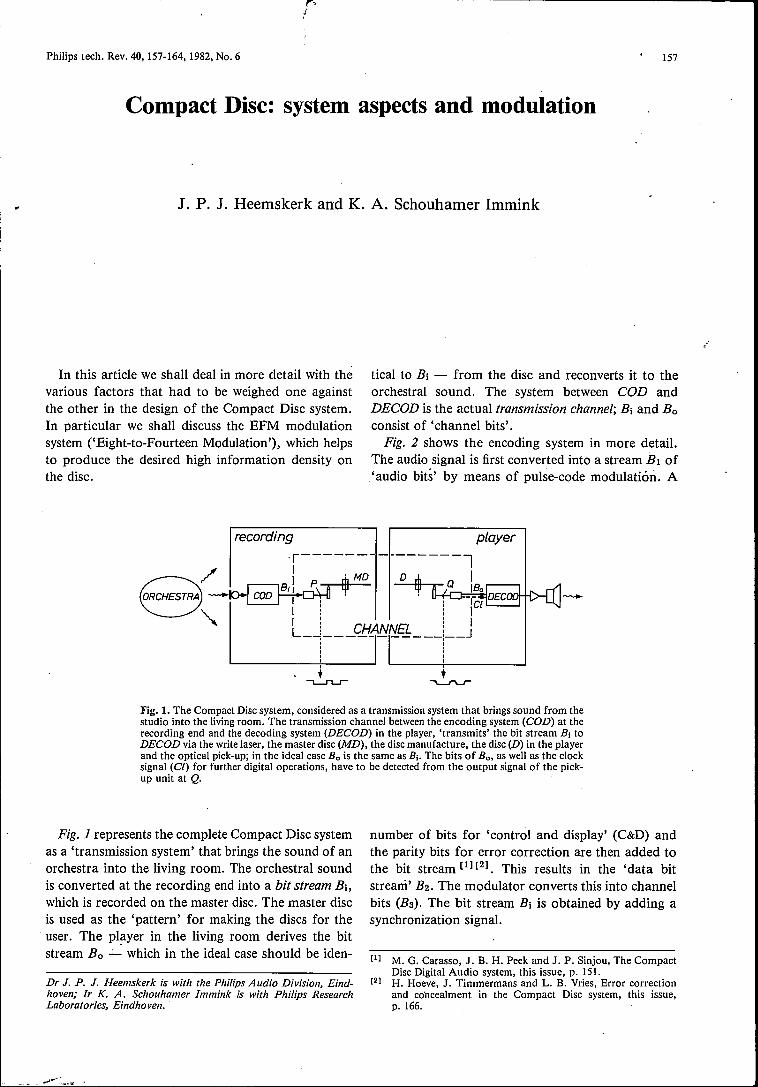
Fig.!. The Compact Disc system, considered as a transmission system that brings sound from thestudio into the living room. The transmission channel between the encoding system (COD) at therecording end and the decoding system (DECaD) in the player, 'transmits' the bit stream Bi toDECOD via the write laser, the master disc (MD), the disc manufacture, the disc (D) in the playerand the optical pick-up; in the ideal case Bo is the same as Bi. The bits of Bo, as well as the clocksignal (Cl) for further digital operations, have to be detected from the output signalof the pick-up unit at Q.
Philips tech. Rev. 40, 157-164, 1982, No. 6
In this article we shall deal in more detail with thevarious factors that had to be weighed one againstthe other in the design of the Compact Disc system.In particular we shall discuss the EFM modulationsystem ('Eight-to-Fourteen Modulation'), which helpsto produce the desired high information density onthe disc.
recording
Fig. 1 represents the complete Compact Disc systemas a 'transmission system' that brings the sound of anorchestra into the living room. The orchestral soundis converted at the recording end into a bit stream Bi,which is recorded on the master disc. The master discis used as the 'pattern' for making the discs for theuser. The player in the living room derives the bitstream Ba .:..._which in the ideal case should be iden-
Dr J. P. J. Heemskerk is with the Philips Audio Division, Eind-hoven; Ir K. A. Schouhamer Immink is with Philips ResearchLaboratories, Eindhoven.
157
tical to Bi - from the disc and reconverts it to theorchestral sound. The system between COD andDECOD is the actual transmission channel; Bi and Baconsist of 'channel bits'.
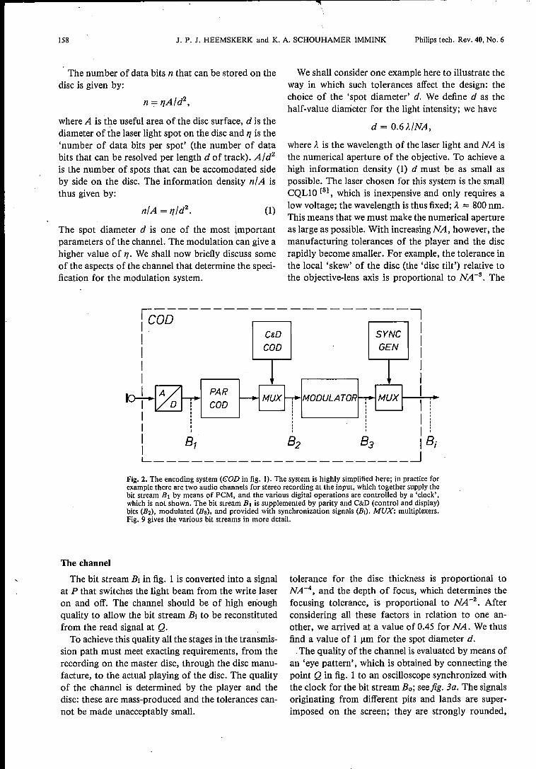
Fig. 2 shows the encoding system in more detail.The audio signal is first converted into a stream 111 of'audio bits' by means of pulse-code modulation. A
number of bits for 'control and display' (C&D) andthe parity bits for error correction are then added tothe bit stream [1] [2]. This results in the 'data bitstream' B2. The modulator converts this into channelbits (Ba). The bit stream Bi is obtained by adding asynchronization signal.
(1] M. G. Carasso, J. B. H. Peek and J. P. Sinjou, The CompactDisc Digital Audio system, this issue, p. 151.
(2] H. Hoeve, J. Timmermans and L. B. Vries, Error correctionand concealment in the Compact Disc system, this issue,p.166.
158 J. P. J. HEEMSKERK and K. A. SCHOUHAMER IMMINK Philips tech. Rev. 40, No. 6
The number of data bits n that can be stored on thedisc is given by:
where A is the useful area of the disc surface, d is thediameter of the laser light spot on the disc and 17is the'number of data bits per spot' (the number of databits that can be resolved per length d of track). A/d2
is the number of spots that can be accomodated sideby side on the disc. The information density n/A isthus given by:
The spot diameter d is one of the most importantparameters of the channel. The modulation can give ahigher value of 17.We shall now briefly discuss someof the aspects of the channel that determine the speci-fication for the modulation system.
We shall consider one example here to illustrate theway in which such tolerances affect the design: thechoice of the 'spot diameter' d. We define d as thehalf-value diameter for the light intensity; we have
d = O.6À/NA,
(1)
where À is the wavelength of the laser light and NA isthe numerical aperture of the objective. To achieve ahigh information density (1) d must be as small aspossible. The laser chosen for this system is the smallCQL10 [3], which is inexpensive and only requires alow voltage; the wavelength is thus fixed; À ::::;800 nm.This means that we must make the numerical apertureas large as possible. With increasing NA, however, themanufacturing tolerances of the player and the discrapidly become smaller. For example, the tolerance inthe local 'skew' of the disc (the 'disc tilt') relative tothe objective-lens axis is proportional to NA -3. The
it--------------------II GOD II ~ S~ II COD GEN II II Ircr+- A PAR II COD III I ,
I :i 81 82 83 18iL ~
Fig. 2. The encoding system (€OD in fig. I). The system is highly simplified here; in practice forexample there are two audio channels for stereo recording at the input, which together supply thebit stream Bl by means of PCM, and the various digital operations are controlled by a 'clock',which is not shown. The bit stream B, is supplemented by parity and C&D (control and display)bits (B2), modulated (Ba), and provided with synchronization signals (Bi). MUX: multiplexers.Fig. 9 gives the various bit streams in more detail.
The channel
The bit stream Bi in fig. lis converted into a signalat P that switches the light beam from the write laseron and off. The channel should be of high enoughquality to allow the bit stream Bi to be reconstitutedfrom the read signal at Q.To achieve this quality all the stages in the transmis-
sion path must meet exacting requirements, from therecording on the master disc, through the disc manu-facture, to the actual playing of the disc. The qualityof the channel is determined by the player and thedisc: these are mass-produced and the tolerances can-not be made unacceptably small.
tolerance for the disc thickness is proportional toNA -4, and the depth of focus, which determines thefocusing tolerance, is proportional to NA -2. Afterconsidering all these factors in relation to one an-other, we arrived at a value of 0.45 for NA. We thusfind a value of 1 urn for the spot diameter d.
The quality of the channel is evaluated by means ofan 'eye pattern', which is obtained by connecting thepoint Q in fig. 1 to an oscilloscope synchronized withthe clock for the bit stream Bo; seefig. 3a. The signalsoriginating from different pits and lands are super-imposed on the screen; they are strongly rounded,
---------------------~- --
Philips tech. Rev. 40, No. 6 COMPACT DISC DIGITAL AUDIO: MODULATION 159
mainly because the spot diameter is not zero and thepit walls are not vertical. If the transmission quality isadequate, however, it is always possible to determinewhether the signal is positive or negative at the 'clocktimes' (the dashes in fig. 3a), and hence to reconstitutethe bit stream. The lozenge pattern around a dash inthis case is called the 'eye'. Owing to channel im-perfections the eye can become obscured; owing
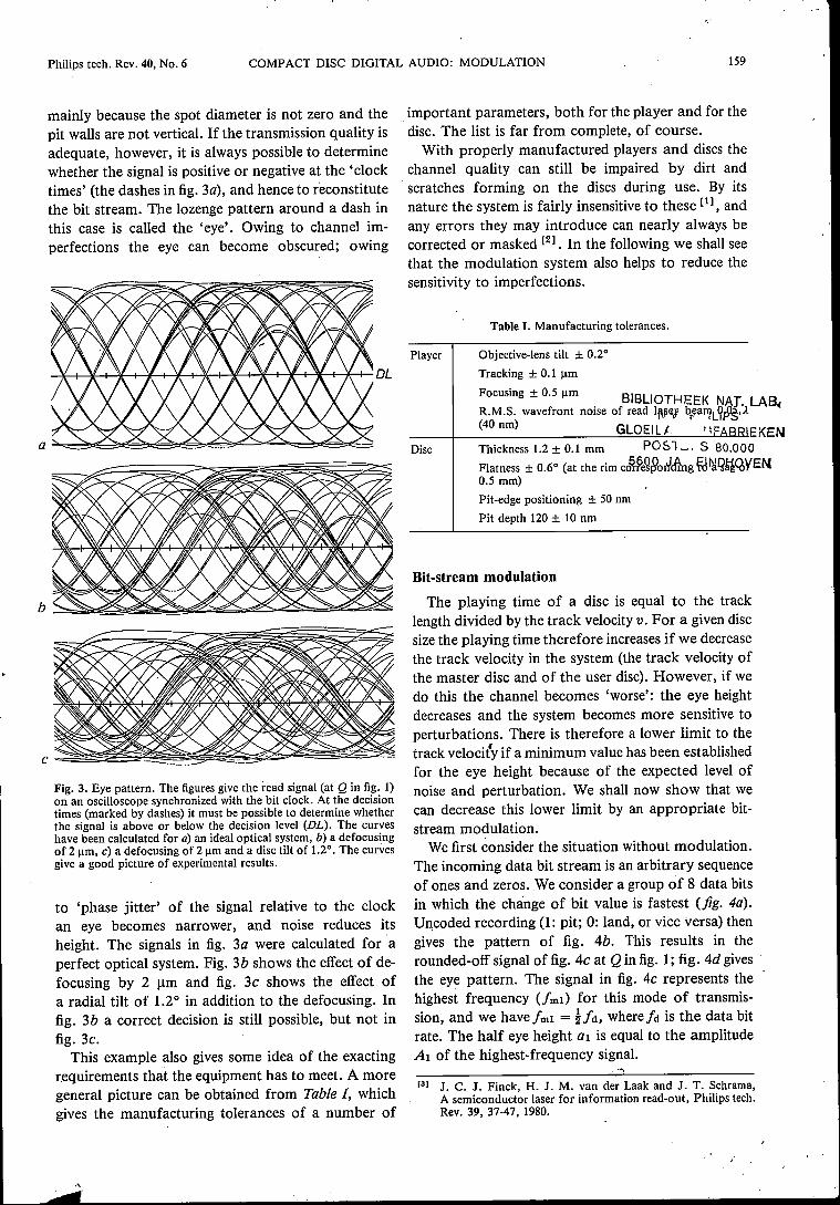
Fig. 3. Eye pattern. The figures give the read signal (at Q in fig. 1)on an oscilloscope synchronized with the bit clock. At the decisiontimes (marked by dashes) it must be possible to determine whetherthe signal is above or below the decision level (DL). The curveshave been calculated for a) an ideal optical system, b) a defocusingof 2 urn, c) a defocusing of 2 urn and a disc tilt of 1.20
• The curvesgive a good picture of experimental results.
to 'phase jitter' of the signal relative to the clockan eye becomes narrower, and noise reduces itsheight. The signals in fig. 3a were calculated for aperfect optical system. Fig. 3b shows the effect of de-focusing by 2 J.Lmand fig. 3c shows the effect ofa radial tilt of 1.2° in addition to the defocusing. Infig. 3b a correct decision is still possible, but not infig. 3c.
This example also gives some idea of the exactingr.equirements that the equipment has to meet. A moregeneral picture can be obtained from Table I, whichgives the manufacturing tolerances of a number of
important parameters, both for the player and for thedisc. The list is far from complete, of course.With properly manufactured players and discs the
channel quality can still be impaired by dirt andscratches forming on the discs during use. By itsnature the system is fairly insensitive to these [1], andany errors they may introduce can nearly always becorrected or masked [2]. In the following we shall seethat the modulation system also helps to reduce thesensitivity to imperfections.
Table I.Manufacturing tolerances.
Disc
Pit-edge positioning ± 50 nmPit depth 120 ± 10 nm
Player Objective-lens tilt ± 0.20
Tracking ± 0.1 JlID
Focusing ± 0.5 JlID BIBLIOT E. H EK NAT. LABR.M.S. wavefront noise of read II\~eJ'¥aI?L9PJs,A ((40 nm) GLOEIL.l '\0::" EKENThickness 1.2 ± 0.1 mm P051....,. S 80.000Flatness ± 0.60 (at the rim c01PeÇ80nldkg~I)lQijQ,YEN0.5 mm)
Bit-stream modulation
The playing time of a disc is equal to the tracklength divided by the track velocity v. For a given discsize the playing time therefore increases if we decreasethe track velocity in the system (the track velocity ofthe master disc and of the user disc). However, if wedo this the channel becomes 'worse': the eye heightdecreases and the system becomes more sensitive toperturbations. There is therefore a lower limit to thetrack velocity if a minimum value has been establishedfor the eye height because of the expected level ofnoise and perturbation. We shall now show that wecan decrease this lower limit by an appropriate bit-stream modulation.We first consider the situation without modulation.
The incoming data bit stream is an arbitrary sequenceof ones and zeros. We consider a group of 8 data bitsin which the change of bit value is fastest (fig. 4a).Uncoded recording (1: pit; 0: land, or vice versa) thengives the pattern of fig. 4b. This results in therounded-off signalof fig. 4c at Q in fig. 1; fig. 4d givesthe eye pattern. The signal in fig. 4c represents thehighest frequency Urnl) for this mode of transmis-sion, and we have!rnl = !!d, where ja is the data bitrate. The half eye height al is equal to the amplitudeAl of the highest-frequency signal.
[3) J. C. J. Finek, H. J. M. van der Laak and J. T. Schrama,A semiconductor laser for information read-out, Philips tech.Rev. 39, 37-47, 1980.
160 J. P. J. HEEMSKERK and K. A. SCHOUHAMER IMMINK Philips tech. Rev. 40, No. 6
-iQ 1 : 0
IIIIIII
o o o
ITmin:I :I I
I
I : I II I I II : : I
Aln V"\ ~ ~ ItP: ~'C7~14 .1 I1 1/fml 1
1 : II
IIII
01>oOOcI II I~T=1/fd
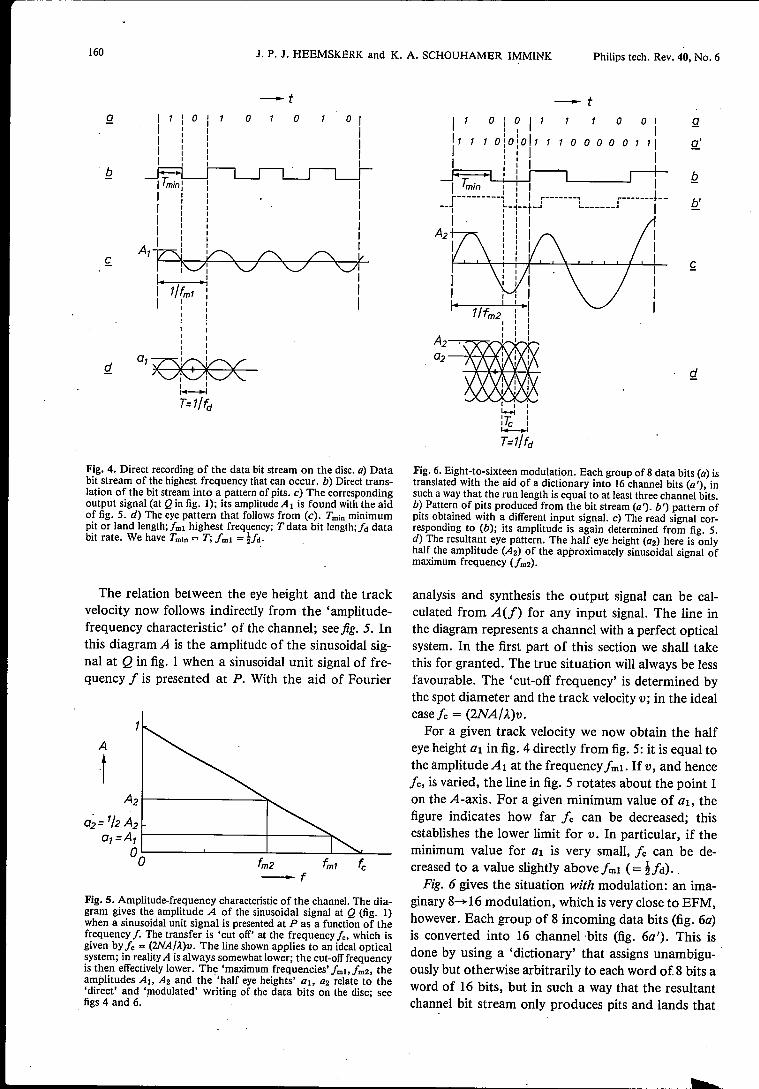
Fig. 4. Direct recording of the data bit stream on the disc. a) Databit stream of the highest frequency that can occur. b) Direct trans-lation of the bit stream into a pattern of pits. c) The correspondingoutput signal (at Q in fig. I); its amplitude Al is found with the aidof fig. 5. d) The eye pattern that follows from (c). Tmin minimumpit or land length;fml highest frequency; Tdata bit length;/d databit rate. We have Tmln= T; fml = !/d.
The relation between the eye height and the trackvelocity now follows indirectly from the 'amplitude-frequency characteristic' of the channel; see fig. 5. Inthis diagram A is the amplitude of the sinusoidal sig-nal at Q in fig. 1 when a sinusoidal unit signalof fre-quency i is presented at P. With the aid of Fourier
A
-tA2~------------~
0;= '/2 A2ol=A,~--------------+-------~
00 fm2 fml-f
Fig. 5. Amplitude-frequency characteristic of the channel. The dia-gram gives the amplitude A of the sinusoidal signal at Q (fig. 1)when a sinusoidal unit signal is presented at P as a function of thefrequency f. The transfer is 'cut off' at the frequency fe, which isgiven by fe = (2NA/À)v. The line shown applies to an ideal opticalsystem; in reality A is always somewhat lower; the cut-off frequencyis then effectively lower. The 'maximum frequencies' fmb [ea, theamplitudes Al. A2 and the -'half eye heights' a}, a2 relate to the'direct' and 'modulated' writing of the data bits on the disc; seefigs 4 and 6.
-iOiO 1 1
I II I I1 10:0:0 1 1: I 1: : II I
I
o 0 I1
'00000"1
1
1~-------~--L J I
Q
A2'~""""'7""V--.i ......_1_... ... !"-"Q2 ---¥--¥--¥
Fig. 6. Eight-to-sixteen modulation. Each group of 8 data bits (a) istranslated with the aid of a dictionary into 16 channel bits (a'), insuch a way that the run length is equal to at least three channel bits.b) Pattern of pits produced from the bit stream (a'). b') pattern ofpits obtained with a different input signal. c) The read signal cor-responding to (b); its amplitude is again determined from fig. 5.d) The resultant eye pattern. The half eye height (a2) here is onlyhalf the amplitude (A2) of the approximately sinusoidal signal ofmaximum frequency (fm2).
analysis and synthesis the output signal can be cal-culated from A(f) for any input signal. The line inthe diagram represents a channel with a perfect opticalsystem. In the first part of this section we shall takethis for granted. The true situation will always be lessfavourable. The 'cut-off frequency' is determined bythe spot diameter and the track velocity v; in the idealcasefe = (2NA/À.)v.For a given track velocity we now obtain the half
eye height al in fig. 4 directly from fig. 5: it is equal tothe amplitude A I at the frequency fmi . If v, and hence[«; is varied, the line in fig. 5 rotates about the point 1on the A-axis. For a given minimum value of al, thefigure indicates how far ie can be decreased; thisestablishes the lower limit for v. In particular, if theminimum value for al is very small, ie can be de-creased to a value slightly above i mt (= !id). _Fig. 6 gives the situation with modulation: an ima-
ginary 8-+ 16 modulation, which is very close to EFM,however. Each group of 8 incoming data bits (fig. 6a)is converted into 16 channel bits (fig. 6a'). This isdone by using a 'dictionary' that assigns unambigu-ously but otherwise arbitrarily to each word of 8 bits aword of 16 bits, but in such a way that the resultantchannel bit stream only produces pits and lands that
Philips tech. Rev. 40, No. 6 COMPACT DISC DIGITAL AUDIO: MODULATION 161
are at least three channel bits long (fig. 6b). On thetime scale the minimum pit and land lengths ('theminimum run length' Tmin) have become I~ times aslong as in fig. 4, but a simple calculation shows thatabout as much information can nevertheless be trans-mitted as in fig. 4 (256 combinations for 8 data bits),because there is a greater choice of pit-edge positionsper unit length (see fig. 6b and bi); the 'channel bitlength' Tc has decreased by a half.
With the modulation we have managed to reducethe highest frequency (fm2) in the signal (see fig. 6c,left; fm2 = kfd = ifml). Therefore fc and v can bereduced by a factor of I~ for the case in which a verysmall eye height is tolerable (see fig. 5); this representsan increase of 50% in playing time.
The modulation also has its disadvantages. In thefirst place the half eye height (a2) in this case is onlyhalf of the amplitude (A2) of the signal at the highestfrequency (see fig. 6d). This has consequences if theminimum eye height is not very small. For example,the modulation becomes completely unusable if thehalf eye height in fig. 5 has to remain larger than ~(a2>~implies A2> 1); uncoded recording is thenstill possible (AI = al). In the second place, the tol-erance for time errors and for the positioning of pitedges, together with the eye width (Tc), has decreasedby a half. In designing a system, the various factorshave to be carefully weighed against one another ..
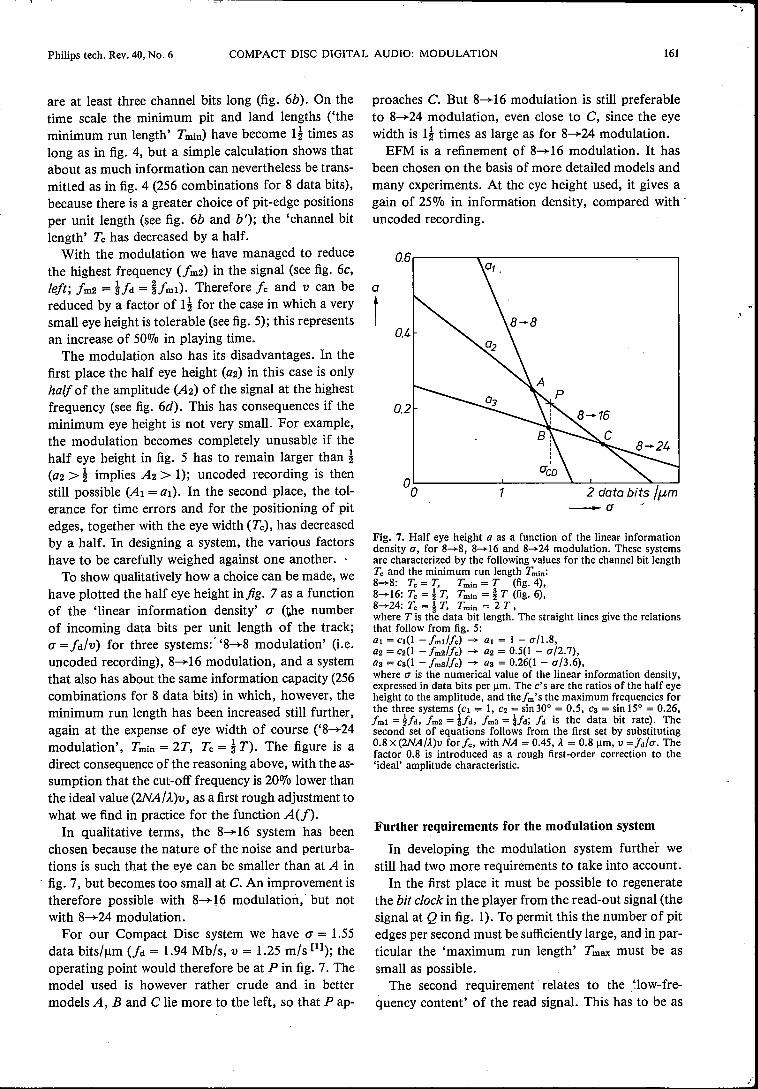
To show qualitatively how a choice can be made, wehave plotted the half eye height infig. 7 as a functionof the 'linear information density' (J (the numberof incoming data bits per unit length of the track;(J = fd/V) for three systems:' '8~8 modulation' (i.e.uncoded recording), 8~I6 modulation, and a systemthat also has about the same information capacity (256combinations for 8 data bits) in which, however, theminimum run length has been increased still further,again at the expense of eye width of course ('8~24modulation', Tmin = 2T, Tc = 1T). The figure is adirect consequence of the reasoning above, with the as-sumption that the cut-off frequency is 20% lower thanthe ideal value (2NA/À)v, as a first rough adjustment towhat we find in practice for the function A(f).
In qualitative terms, the 8~ 16 system has beenchosen because the nature of the noise and perturba-tions is such that the eye can be smaller than at A in
. fig. 7, but becomes too small at C. An improvement istherefore possible with 8~I6 modulation; but notwith 8~24 modulation.
For our Compact Disc system we have (J = 1.55data bits/urn (fd = 1.94 Mb/s, v = 1.25 mis [1]); theoperating point would therefore be at P in fig. 7. Themodel used is however rather crude and in bettermodels A, Band C lie more to the left, so that P ap-
proaches C. But 8~ 16 modulation is still preferableto 8~24 modulation, even close to C, since the eyewidth is I~ times as large as for 8~24 modulation.
EFM is a refinement of 8~I6 modulation. It hasbeen chosen on the basis of more detailed models andmany experiments. At the eye height used, it gives again of 250/0 in information density, compared with'uncoded recording.
a
t
Fig. 7. Half eye height a as a function of the linear informationdensity u, for 8-+8, 8-+16 and 8-+24 modulation. These systemsare characterized by the following values for the channel bit lengthTc and the minimum run length Tmin:8-+8: Tc = T, Tmin = T (fig. 4),8-+16: Tc = lT, Tmin = ~T (fig. 6),8-+24: Tc = 1T, Tmin = 2 T,where T is the data bit length. The straight lines give the relationsthat follow from fig. 5:al = cI(1 - fml/fe) -+ al = 1 - u/1.8,a2 = C2(1 - fm2/fe) -+ az = 0.5(1 - u/2.7),a3 = cs(l - fms/fe) -+ as = 0.26(1 - u/3.6),where u is the numerical value of the linear information density,expressed in data bits per urn, The c's are the ratios of the half eyeheight to the amplitude, and thefm's the maximum frequencies forthe three systems (Cl = 1, C2 = sin 30° = 0.5, Cs = sin 15° = 0.26,fml = lid, fm2 = lid, fm3 = !/d; /d is the data bit rate). Thesecond set of equations follows from the first set by substituting0.8 x (2NA/À.)v for fe, with NA = 0.45, À.= 0.8 urn, V =/d/u. Thefactor 0.8 is introduced as a rough first-order correction to the'ideal' amplitude characteristic.
Further requirements for the modulation system
In developing the modulation system further westill had two more requirements to take into account .
In the first place it must be possible to regeneratethe bit clock in the player from the read-out signal (thesignal at Q in fig. I). To permit this the number of pitedges per second must be sufficiently large, and in par-ticular the 'maximum run length' Tmax must be assmall as possible.
The second requirement' relates to the 'low-fre-quency content' of the read signal. This has to be as
162 J. P. J. HEEMSKERK and K. A. SCHOUHAMER IMMINK Philips tech. Rev. 40, No. 6
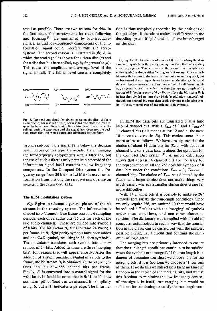
small as possible. There are two reasons for this. Inthe first place, the servosystems for track followingand focusing [1] are controlled by low-frequencysignals, so that low-frequency components of the in-formation signal could interfere with the servo-systems. The second reason is illustrated in fig. 8, in. which the read signal is shown for a clean disc (a) andfor a disc that has been soiled, e.g. by fingermarks (b).This causes the amplitude and average level of thesignal to fall. The fall in level causes a completely
100% 100% 50%-----
DL-~ ~ O%~-
0% 0% -50%-----
g
Fig. 8. The read-out signal for six pit edges on the disc, a) for aclean disc, b) for a soiled disc, c) for a soiled disc after the low fre-quencies have been filtered out. DL decision level. Because of thesoiling, both the amplitude and the signal level decrease; the deci-sion errors that this would cause are eliminated by the filter.
wrong read-out if the signal falls below the decisionlevel. Errors of this type are avoided by eliminatingthe low-frequency components with a filter (c), butthe use of such a filter is only permissible provided theinformation signal itself contains no low-frequencycomponents. In the Compact Disc system the fre-quency range from 20 kHz to 1.5 MHz is used for in-formation transmission; the servosystems operate onsignals in the range 0-20 kHz.
\
The EFM modulation system
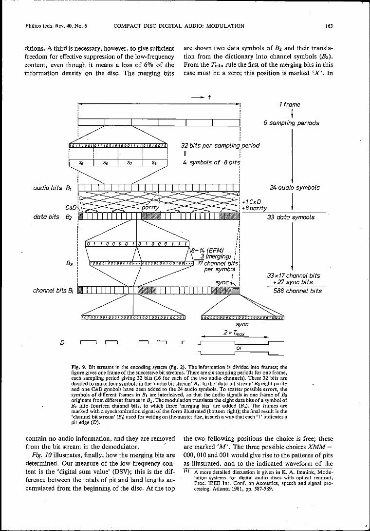
Fig. 9 gives a schematic general picture of the bitstreams in the encoding system. The information isdivided into 'frames'. One frame contains 6 samplingperiods, each of 32 audio bits (16 bits for each of thetwo audio channels). These are divided into symbolsof 8 bits. The bit stream Bi thus contains 24 symbolsper frame. In B2 eight parity symbols have been addedand one C&D symbol, resulting in 33 'data symbols'.The modulator translates each symbol into a newsymbol of 14 bits. Added to these are three 'mergingbits', for reasons that will appear shortly. After theaddition of a synchronization symbol of 27 bits to theframe, the bit stream Bi is obtained. Bi therefore con-tains 33 X 17 + 27 = 588 channel bits per frame.Finally, Bi is converted into a control signal for thewrite laser. It should be noted that in Bi '1' or '0' doesnot mean 'pit' or 'land', as we assumed for simplicityin fig. 6, but a '1' indicates a pit edge. The informa-
tion is thus completely recorded by the positions ofthe pit edges; it therefore makes no difference to thedecoding system if 'pit' and 'land' are interchangedon the disc.
Opting for the translation of series of 8 bits following the divi-sion into symbols in the parity coding has the effect of avoidingerror propagation. This is because in the error-correction system anentire symbol is always either 'wrong' or 'not wrong'. One channel-bit error that occurs in the transmission spoils an entire symbol, but- because of the correspondence between modulation symbols anddata symbols - never more than one symbol. If a different modul-ation system is used, in which the data bits are not translated ingroups of 8, but in groups of 6 or 10, say, then the bit stream B2 isin fact first divided up into 6 or IQbit 'modulation symbols'. Al-though one channel-bit error then spoils only one modulation sym-bol, it usually spoils two of the original 8 bit symbols.
In EFM the data bits are translated 8 at a timeinto 14 channel bits, with a Tmin of 3 and a Tmax of11 channel bits (this means at least 2 and at the most10 successive zeros in Bi). This choice came aboutmore or less as follows. We have already seen that thechoice of about I! data bits for Tmin, with about 16channel bits on 8 data bits, is about the optimum forthe Compact Disc system [4]. A simple calculationshows that at least 14 channel bits are necessary forthe reproduetion of all the 256 possible symbols of 8data bits under the conditions Tmin = 3, Tmax = 11channel bits. The choice of Tmax was dictated by thefact that a larger choice does not make things verymuch easier, whereas a smaller choice does create farmore difficulties.
With 14 channel bits it is possible to make up 267symbols that satisfy the run-length conditions. Sincewe only require 256, we omitted 10 that would haveintroduced difficulties with the 'merging' of symbolsunder these conditions, and one other chosen atrandom. The dictionary was compiled with the aid ofcomputer optimization in such a way that the transla-tion in the player can be carried out with the simplestpossible circuit, i.e. a circuit that contains the mini-mum of logic gates.The merging bits are primarily intended to ensure
that the run-length conditions continue to be satisfiedwhen the symbols are 'merged' . If the run length is indanger of becoming too short we choose 'O's for themerging bits; if it is too long we choose a '1' for oneof them. Ifwe do this we still retain a large measure offreedom in the choice of the merging bits, and we usethis freedom to minimize the low-frequency contentof the signal. In itself, two merging bits would be.sufficient for continuing to satisfy the run-length con-
Philips tech. Rev. 40, No. 6 COMPACT DISC DIGITAL AUDIO: MODULATION 163
are shown two data symbols of B2 and their transla-tion from the dictionary into channel symbols (Ba).From the Tmin rule the first of the merging bits in thiscase must be a zero; this position is marked 'X'. In
ditions. A third is necessary, however, to give sufficientfreedom for effective suppression of the low-frequencycontent, even though it means a loss of 6070 of theinformation density on the disc. The merging bits
-t1 frame
t6 sampling periods
32 bits per sampling period
" l,4 symbols of 8 bits ,,
24 audio symbols
1+1C&D-Bporiiy
33 data symbols,""""""
+14 (EFM) !i3 (merging) ; i
~~~~~~~~~~~~~~-1717channelbffs:per symbol: ,,, 33 x 17 channel bits
+ 27 sync bits588 channel bits
sync2xTmax
D _j ,--or., L___
Fig. 9. Bit streams in the encoding system (fig. 2). The information is divided into frames; thefigure gives one frame of the successive bit streams. There are six sampling periods forone frame,each sampling period giving 32 bits (16 for each of the two audio channels). These 32 bits aredivided to make four symbols in the 'audio bit stream' BI. In the 'data bit stream' B2 eight parityand one C&D symbols have been added to the 24 audio symbols. To scatter possible errors, thesymbols of different frames in BI are interleaved, so that the audio signals in one frame of B2originate from different frames in BI. The modulation translates the eight data bits of a symbol ofB2 into fourteen channel bits, to which three 'merging bits' are added (Bs). The frames aremarked with a synchronization signalof the form illustrated (bottom right); the final result is the'channel bit stream' (BI) used for writing on the.master disc, in such a way that each' l' indicates apit edge (D).
contain no audio information, and they are removedfrom the bit stream in the demodulator. /Fig. 10 illustrates, finally, how the merging bits are
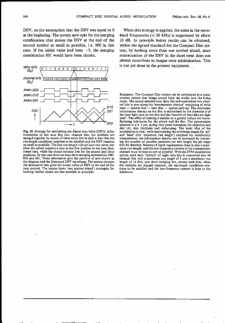
determined. Our measure of the low-frequency con-tent is the 'digital sum value' (DSV); this is the dif-ference between the totals of pit and land lengths ac-cumulated from the beginning of the disc. At the top
the two following positions the choice is free; theseare marked 'M'. The three possible choices XMM =,000,010 and 001 would give rise to the patterns of pitsas illustrated, and to the indicated waveform of the[4] A more detailed discussion is given in K. A. Immink, Modu-
lation systems for digital audio discs with optical readout,Proc. IEEE Int. Conf. on Acoustics, speech and signal pro-cessing, Atlanta 1981, pp. 587-589.
164 COMPACT DISC DIGITAL AUDIO: MODULATION Philips tech. Rev. 40, No. 6
DSV, on the assumption that the DSV was equal to 0at the beginning. The system now opts for the mergingcombination that makes the DSV at the end of thesecond symbol as small as possible, i.e. 000 in thiscase. If the initial value had been -3, the mergingcombination 001 would have been chosen.
o 1 100 0 0 1
channel bits 'r:-:=-=""""':-:::-:~'"""';-;-;"="'+'O::-:O::-:I;-:O::-:O::-:I;-;O::-:O'-:I;-:O::-:O;-:';-:O'"'Od:M:-:-(83)
XMM=OOOXMM=010·
XMM=001
/., /., !I 010).. .1'.,.'., .>; " : 001,.:.,. .' ,. .'.:» r{ ........I
II
DSV
t000
Fig. 10. Strategy for minimizing the digital sum value (DSV). Aftertranslation of the data bits into channel bits, the symbols aremerged together by means of three extra bits in such a way that therim-length conditions continue to be satisfied and the DSV remainsas small as possible. The first run-length rule (at least two zeros oneafter the other) requires a zero at the first position in the case illus-trated here, while the choice remains free for the second and thirdpositions. In this case there are thus three merging alternatives: 000,010 and 001. These alternatives give the patterns of pits shown inthe diagram and the illustrated DSV waveform. The system choosesthe alternative that gives the lowest value of DSV at the end of thenext symbol. The system looks 'one symbol ahead'; strategies forlooking further ahead are also possible in principle.
When this strategy is applied, the noise in the servo-band frequencies « 20 kHz) is suppressed by about10 dB. In principle better results can be obtained,within the agreed standard for the Compact Disc sys-tem, by looking more than one symbol ahead, sinceminimization of the DSV in the short term does notalways contribute to longer-term minimization. Thisis not yet done in the present equipment.
Summary. The Compact Disc system can be considered as a trans-mission system that brings sound from the studio into the livingroom. The sound encoded into data bits and modulated into chan-nel bits is sent along the 'transmission channel' consisting of writelaser - master disc - user disc - optical pick-up. The maximuminformation density on the disc is determined by the diameter dofthe laser light spot on the disc and the 'number of data bits per lightspot'. The effect of making d smaller is to greatly reduce the manu-facturing tolerances for the player and the disc. The compromiseadopted is d'" 1 urn, giving very small tolerances for objective anddisc tilt, disc thickness and defocusing. The basic idea of themodulation is that, while maintaining the minimum length for 'pit'and 'land' (the 'minimum run length') required for satisfactorytransmission, the information density can be increased by increas-ing the number of possible positions per unit length for pit edges(the bit density). Because of clock regeneration there is also a maxi-mum run length, and the low-frequency content ofthe transmissionchannel must be kept as low as possible. With the EFM modulationsystem used each 'symbol' of eight data bits is converted into 14channel bits with a minimum run length of 3 and a maximum runlength of 11 bits, plus three merging bits, chosen such 'that, whenthe symbols are merged together, the run-length conditions con-tinue to be satisfied and the low-frequency content is kept to theminimum.
Philips tech. Rev. 40,1982, No. 6
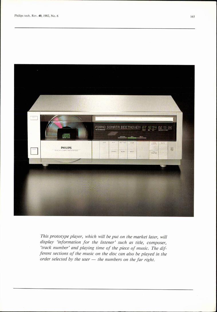
This prototype player, which will be put on the market later, willdisplay 'information for the listener' such as title, composer,'track number' and playing time of the piece of music. The dif-ferent sections of the music on the disc can also be played in theorder selected by the user - the numbers on the far right.
165