COMP-361 7 Specifying Structural Requirements - cs…joerg/SEL/COMP-361_Handouts_files/COMP-361...
49
COMP-361 Specifying Structural Requirements Specifying Structural Requirements Jörg Kienzle & Alfred Strohmeier
Transcript of COMP-361 7 Specifying Structural Requirements - cs…joerg/SEL/COMP-361_Handouts_files/COMP-361...

COMP-361 Specifying Structural Requirements
Specifying Structural Requirements
Jörg Kienzle & Alfred Strohmeier

COMP-361 Specifying Structural Requirements © 2014 Jörg Kienzle
Structural Requirements Overview
• Purpose and Process of Requirements Specification / Analysis Phase!
• Environment Model!• Actors!• Messages!• System Operations!
• Concept Model
2

COMP-361 Specifying Structural Requirements © 2014 Jörg Kienzle
Requirements Specification Phase
• Purpose!• To produce a complete, consistent, and unambiguous description of !
• the problem domain and!• the functional requirements of the system.!
• Models are produced, which describe!• Structural Models!
• Environment Model!• Defines the system’s interface, i.e. the boundaries of the system and the
operations that can be performed on the system.!• Concept Model!
• Defines the static structure of the information in the system, i.e. the concepts that exist in the system, and the relationships between them!
• Behavior Models (see next lecture)!• The models concentrate on describing what a system does, rather than how it
does it.
3

COMP-361 Specifying Structural Requirements © 2014 Jörg Kienzle
Fondue Models: Requirements Spec.
4
Requirements Specification and Analysis Models
Environment Model
Protocol ModelOperation Model
Concept Model
UML Class Diagram, describing the conceptual
state of the system
UML Communication Diagram, describing the system interface (i.e. system
boundary and input / output messages)

COMP-361 Specifying Structural Requirements © 2014 Jörg Kienzle
Requirements Specification Process
5
• From Requirements Elicitation:!• Use Case Model!• Domain Model!
1.Develop the Environment Model!• Identify actors, messages and system operations!
2.Produce the Concept Model!• By adding the system boundary to the Domain Model!
3.Develop the Protocol Model (next lecture)!4.Develop the Operation Model (next lecture)!
• Update Concept Model if needed!5.Check the requirements models for consistency and
completeness

COMP-361 Specifying Structural Requirements © 2014 Jörg Kienzle
Environment Model (1)• The Environment Model defines the system
interface!• It shows a black-box view of the system!• It determines how the system functionality is mapped onto
individual operations!• It is designed based on the domain model and the use case model!• Technical decisions are needed concerning the amount of
communication traffic / data that will be sent to / from the system
6

COMP-361 Specifying Structural Requirements © 2014 Jörg Kienzle
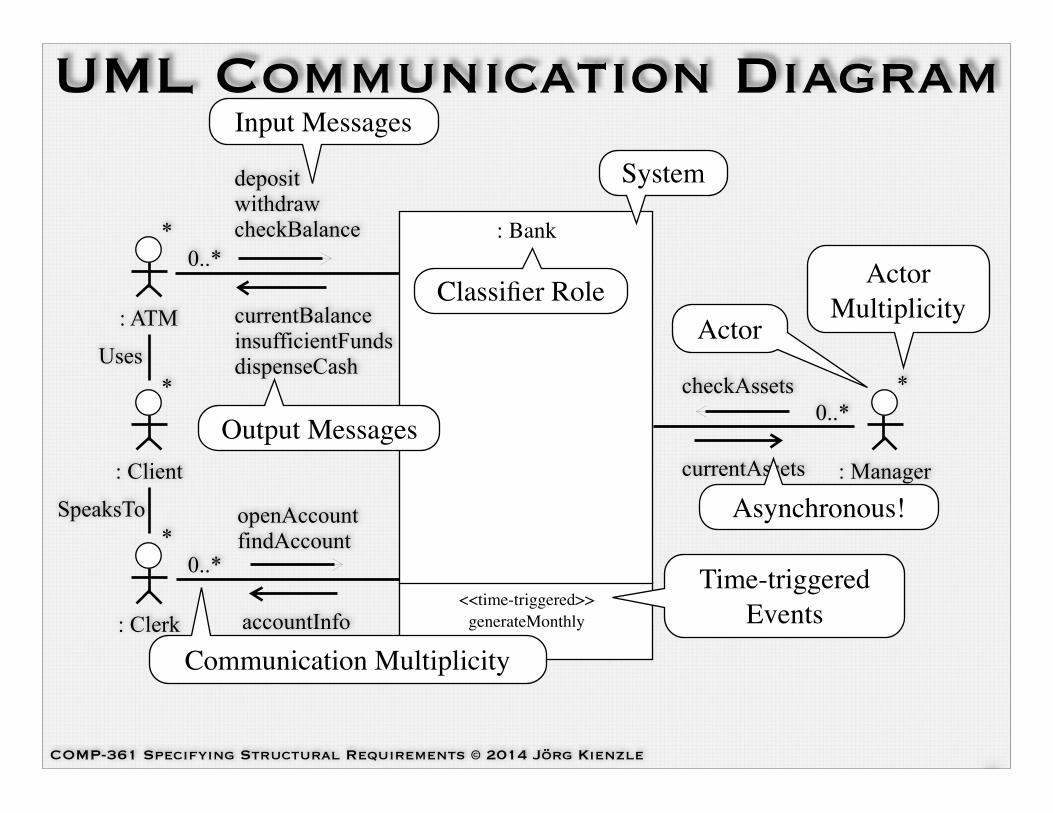
Environment Model (2)• The system is modelled as a reactive entity that
interacts with other active, reactive and passive entities called actors.!• The system is just a name for the actor that is being analyzed.!• The environment is the set of actors with which a system
communicates.!• The actors communicate with the system by
sending input messages and by receiving output messages.!• An input message is always sent by an actor, never by an object in
the system.
7
COMP-361 Specifying Structural Requirements © 2014 Jörg Kienzle
<<time-triggered>> generateMonthly
: Bank
UML Communication Diagram
8
0..*
: ATM
: Client
: Clerk
*
0..**
*
: Manager
*0..*
Uses
SpeaksTo
deposit withdraw checkBalance
currentBalance insufficientFunds dispenseCash
openAccount findAccount
accountInfo
checkAssets
currentAssets
Classifier Role
System
Input Messages
Output Messages
Asynchronous!
Time-triggered Events
Actor
Actor Multiplicity
Communication Multiplicity

COMP-361 Specifying Structural Requirements © 2014 Jörg Kienzle
Messages (1)
9
• A message instance is an instantaneous and atomic unit of communication between the system and its environment!
• The communication is asynchronous: the sender does not wait for the message instance to be received!
• The sender may supply parameters, i.e. data values and objects, with a message instance!
• Example message type:!
Deposit(a : Account, amount : Real)

COMP-361 Specifying Structural Requirements © 2014 Jörg Kienzle
Message Parameters• During requirements specification, classes (in the
concept model) represent concepts relevant to the problem domain!• It has not yet been decided how these concepts are going to be
represented within the design of the software being built!• Defining message types with objects as
parameters is perfectly ok!• It means that conceptually, the object (i.e. its identity and the state
it encapsulates) is passed along with the message!• During design, a way of passing the object’s identity and state
needs to be devised
10
COMP-361 Specifying Structural Requirements © 2014 Jörg Kienzle
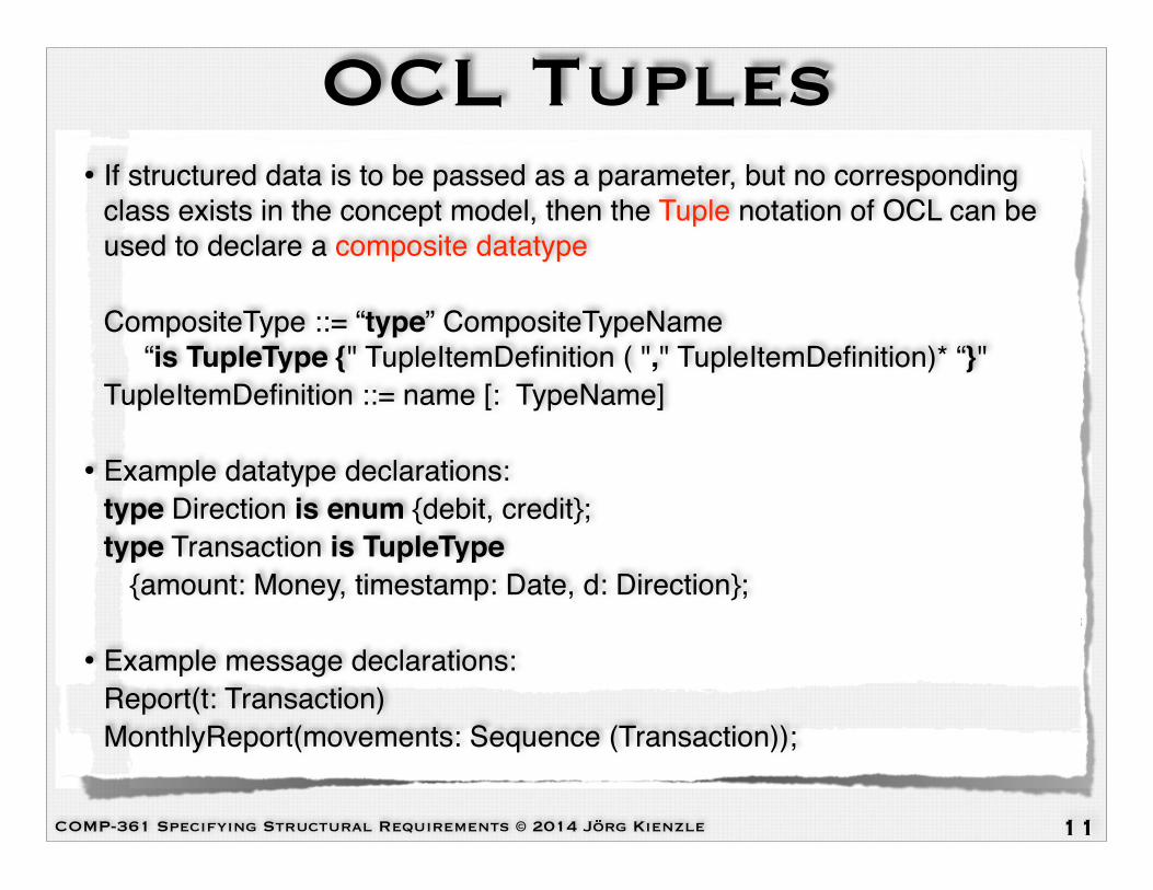
OCL Tuples• If structured data is to be passed as a parameter, but no corresponding
class exists in the concept model, then the Tuple notation of OCL can be used to declare a composite datatype!!CompositeType ::= “type” CompositeTypeName “is TupleType {" TupleItemDefinition ( "," TupleItemDefinition)* “}"!TupleItemDefinition ::= name [: TypeName]!!
• Example datatype declarations:!type Direction is enum {debit, credit};!type Transaction is TupleType!! {amount: Money, timestamp: Date, d: Direction};!!
• Example message declarations:!Report(t: Transaction)!MonthlyReport(movements: Sequence (Transaction));
11
COMP-361 Specifying Structural Requirements © 2014 Jörg Kienzle
Messages (2)• A message instance received by the system (or
another actor) triggers an event that is delivered to the system’s state machine, ready to be processed!• The event generated by the reception of a message has the same
signature as the message!• In addition to events triggered by the reception of
messages, there might be time-triggered events the system has to deal with
12

COMP-361 Specifying Structural Requirements © 2014 Jörg Kienzle
System Operations• Processing an input event (time-triggered or triggered
by receiving a message) can cause a change of system state and the output of messages!
• The effect associated with an input event is called a system operation!• An input event therefore triggers a system operation!
• A system operation is performed instantaneously!• This is a simplifying assumption during requirements specification!• At design time this assumption does not hold!!
• At any one point in time, only one input event can arise, and therefore only one system operation can be active
13

COMP-361 Specifying Structural Requirements © 2014 Jörg Kienzle
Environment Model (3)• The Environment Model is defined by!
• The set of input messages the system can receive!• The set of time-triggered input events (which together define the
set of system operations), and!• The set of messages the system can output!
• A major factor is the granularity of data associated with messages / operations:!• Large grained operations lead to batch processing, e.g.,
processing a collection of orders.!• Small grained operations lead to interactive systems, e.g.
processing each order in turn, and providing individual feedback.
14

COMP-361 Specifying Structural Requirements © 2014 Jörg Kienzle
Actors and Messages• Usually, many different actors may produce the same kinds
of messages triggering the same system operations. The effect of the operation does not depend on the sending actor, only on the actual message attributes!• Example: The clerk of the bank, but also the client himself / herself might want to
get the balance of an account!
• Some systems interact with well identified single actors!• Example: The system software of a terminal interacts with a pointing device, a
keyboard, and a screen!
• Sometimes, there are many “identical” actors, maybe even varying over time, interacting with the system. In that case, it is important to distinguish between “only one actor at any given time” and “many concurrent actor instances”
15

COMP-361 Specifying Structural Requirements © 2014 Jörg Kienzle
Actor and Communication Multiplicities (1)
• We are considering the working of just a single ATM. A single terminal is linked to this ATM; it is “its” terminal. There are many clients in the environment.!
• There might or might not be a client in front of the terminal. One client at a time has access to the terminal, and all output messages are sent to that terminal.
16
: ATM1
: Terminal
10..1
: Client
*
10..1

COMP-361 Specifying Structural Requirements © 2014 Jörg Kienzle
Actor and Communication Multiplicities (2)
• There are exactly two players. They might issue the same input messages, but the computerized game has to send output messages to the right player (or terminal).!• They play different roles
17
: Game
1
white : Player
1
1
1
black : Player
1
1
COMP-361 Specifying Structural Requirements © 2014 Jörg Kienzle
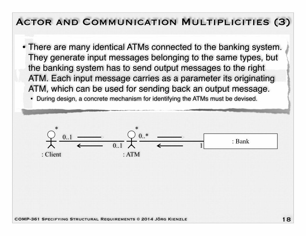
Actor and Communication Multiplicities (3)
• There are many identical ATMs connected to the banking system. They generate input messages belonging to the same types, but the banking system has to send output messages to the right ATM. Each input message carries as a parameter its originating ATM, which can be used for sending back an output message.!• During design, a concrete mechanism for identifying the ATMs must be devised.
18
: Bank0..*
: ATM
*0..1
: Client
*
10..1

COMP-361 Specifying Structural Requirements © 2014 Jörg Kienzle
Actor and Communication Multiplicities (4)
• The manager triggers some operation, and as a result all or some clients are sent a message.!• The Bank Concept Model then must contain a class, e.g. Customer,
representing the client actors, and an <<id>> stereotyped association between the two. This association is used for identifying the actor instances to whom messages are sent to.
19
: Bank 0..*
: Client
*0..*
: Manager
*
0..1
<<system>> Bank
Customer * 1
Client
*1
<<id>> Represents
Concept Model:
Environment Model:
COMP-361 Specifying Structural Requirements © 2014 Jörg Kienzle
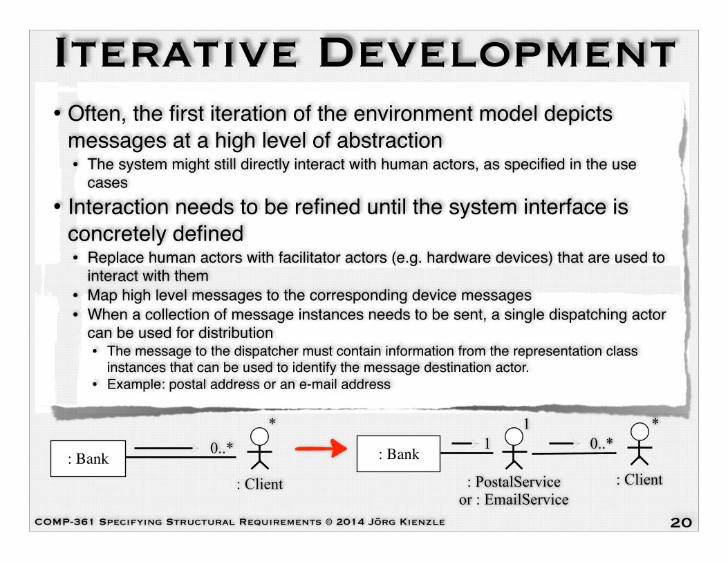
Iterative Development• Often, the first iteration of the environment model depicts
messages at a high level of abstraction!• The system might still directly interact with human actors, as specified in the use
cases!
• Interaction needs to be refined until the system interface is concretely defined!• Replace human actors with facilitator actors (e.g. hardware devices) that are used to
interact with them!• Map high level messages to the corresponding device messages!• When a collection of message instances needs to be sent, a single dispatching actor
can be used for distribution!• The message to the dispatcher must contain information from the representation class
instances that can be used to identify the message destination actor.!• Example: postal address or an e-mail address
20
: Bank 0..*
: Client
*0..*
: Client
*
: PostalService or : EmailService
1
: Bank 1
COMP-361 Specifying Structural Requirements © 2014 Jörg Kienzle
Terminal Question• Provide declarations for the entities needed to
describe the exchange of information by messages between a system and a terminal “actor”.!• On a terminal, characters can be input, one at a time!• A terminal can display characters, one at a time, in three modes:
regular, inverted, and underlined.
21

COMP-361 Specifying Structural Requirements © 2014 Jörg Kienzle
Printer Question• The printer “actor” provides printing lines of characters, one line
at a time, and informs the system when printing of a line is terminated. The printer also informs the system when an incident makes it impossible to continue printing. Some possible problems are: out of paper, paper jam, lack of ink, and some other cases that will be defined later on during the project, and which should be easy to add when time comes. When an incident arises, the system must acknowledge the error, deciding if the current printing should be canceled or if the printer should retry.!
1.Establish an Environment Model!2.Provide message declarations for both the input and output
messages. If needed, provide also data type declarations.
23

COMP-361 Specifying Structural Requirements © 2014 Jörg Kienzle
Concept Model (1)• The Concept Model contains the set of classes
and associations modelling the system’s conceptual state!
• The Concept Model must contain all conceptual system state needed in order to provide the required system functionality!• For each system operation, reflect on what conceptual state is
needed to execute its functionality!• Often, new concepts need to be added to the Concept Model once the
behavioural specification models (Operation Model) are being developed!
• The Concept Model should not contain state that is not needed to provide the required system functionality
26

COMP-361 Specifying Structural Requirements © 2014 Jörg Kienzle
Domain Model ➙ Concept Model
• Classes and relationships from the Domain Model can specify concepts belonging to the system itself, as well as to its environment.!
• The Concept Model only contains the classes and relationships of the Domain Model that relate to the system to be built.!
• The Concept Model is built by delimiting in the Domain Model what is inside of the system from what is outside of it. The Concept Model is therefore formed by excluding all the objects, classes and relationships that belong exclusively to the environment.
27

COMP-361 Specifying Structural Requirements © 2014 Jörg Kienzle
Concept Model (2)• Actors, for example, belong to the environment.
Associations connecting them to the system correspond to communication paths between actors and the system.!• When a class is outside of the system boundary, and if its instances interact
with the system, then these instances are in fact actors.!• If an association is in the Concept Model, then all
connected classes must also be in the model (well-formed class model)!• Hence actors that interact with the system directly are included in the
Concept Model!• If everything is in the system, then the system is a
simulation model (no interaction with the environment).
28

COMP-361 Specifying Structural Requirements © 2014 Jörg Kienzle
Concept Model (3)• The Concept Model is a class diagram, where the
system is shown explicitly as a composite class (stereotyped <<system>>) with a single instance, using graphical nesting of all the entities belonging to the system. As a consequence, all classes in the system get an explicit multiplicity that shows the number of instances within the system.!
• Actors are modelled like classes belonging to the environment, together with their multiplicity in the environment, as viewed by the system.!• Associations (often unnamed) depict the flows of messages between the
system and the actors.
29
COMP-361 Specifying Structural Requirements © 2014 Jörg Kienzle
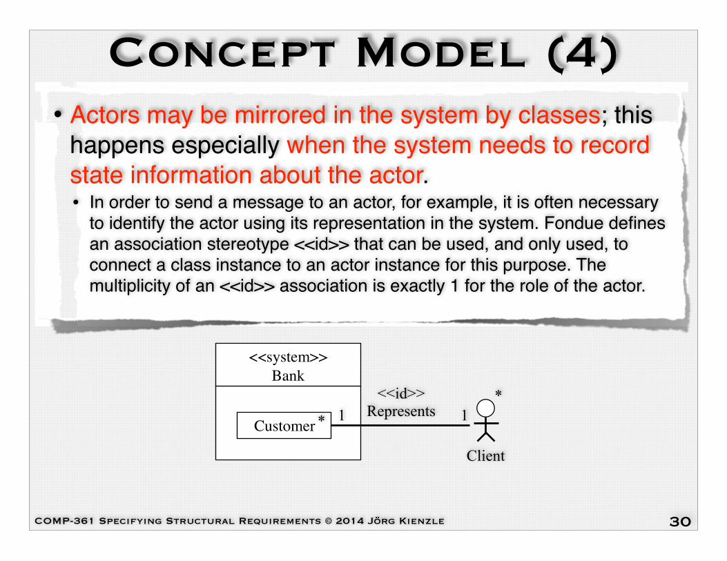
Concept Model (4)• Actors may be mirrored in the system by classes; this
happens especially when the system needs to record state information about the actor.!• In order to send a message to an actor, for example, it is often necessary
to identify the actor using its representation in the system. Fondue defines an association stereotype <<id>> that can be used, and only used, to connect a class instance to an actor instance for this purpose. The multiplicity of an <<id>> association is exactly 1 for the role of the actor.
30
<<system>> Bank
Customer * 1
Client
*1
<<id>> Represents

COMP-361 Specifying Structural Requirements © 2014 Jörg Kienzle
Concept Model Example (1)
31
Employee
Manager Clerk
Bank0..*employee
Account Client
Transaction ATM
Owns0..* 1
Manages TalksTo
Uses0..* history1..2
System
1
We’re developing the software for one bank, hence we don’t need to
include this concept
We want to store information about clients, but clients also
interact with the system, hence we need to split clients into two
separate concepts

COMP-361 Specifying Structural Requirements © 2014 Jörg Kienzle
<<system>> Bank
Concept Model Example (2)
32
Account Customer
Transaction
Owns0..* 1
0..* history1..2
1
Client
*1<<id>>
Clerk
*
Manager
*
ATM
*
**
* Calendar 1
We need to keep track of the current date in order to
correctly initialize the date fields of the Transaction class
COMP-361 Specifying Structural Requirements © 2014 Jörg Kienzle
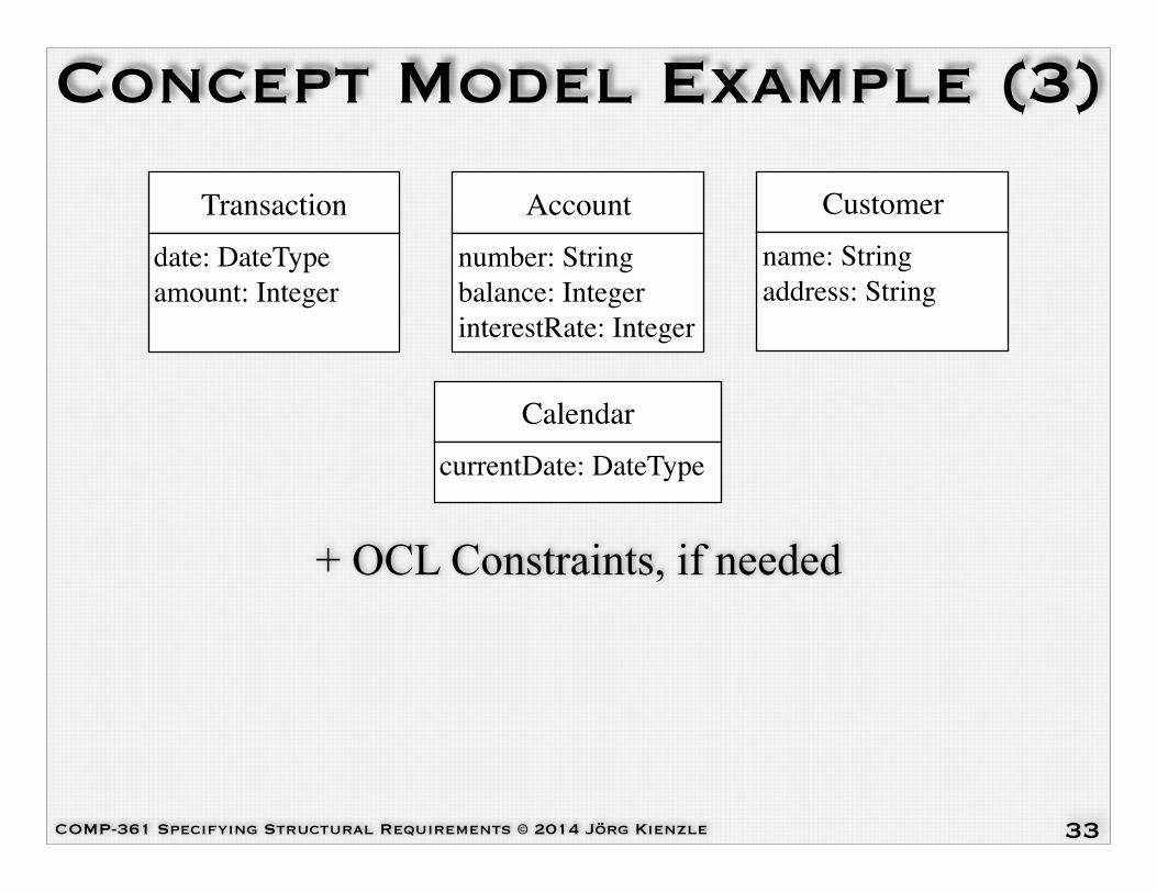
Concept Model Example (3)
33
Transactiondate: DateType amount: Integer
Accountnumber: String balance: Integer interestRate: Integer
Customername: String address: String
+ OCL Constraints, if needed
CalendarcurrentDate: DateType

COMP-361 Specifying Structural Requirements © 2014 Jörg Kienzle
Questions?
34
? ???
??
? ??
COMP-361 Specifying Structural Requirements © 2014 Jörg Kienzle
Gas Station Problem Statement
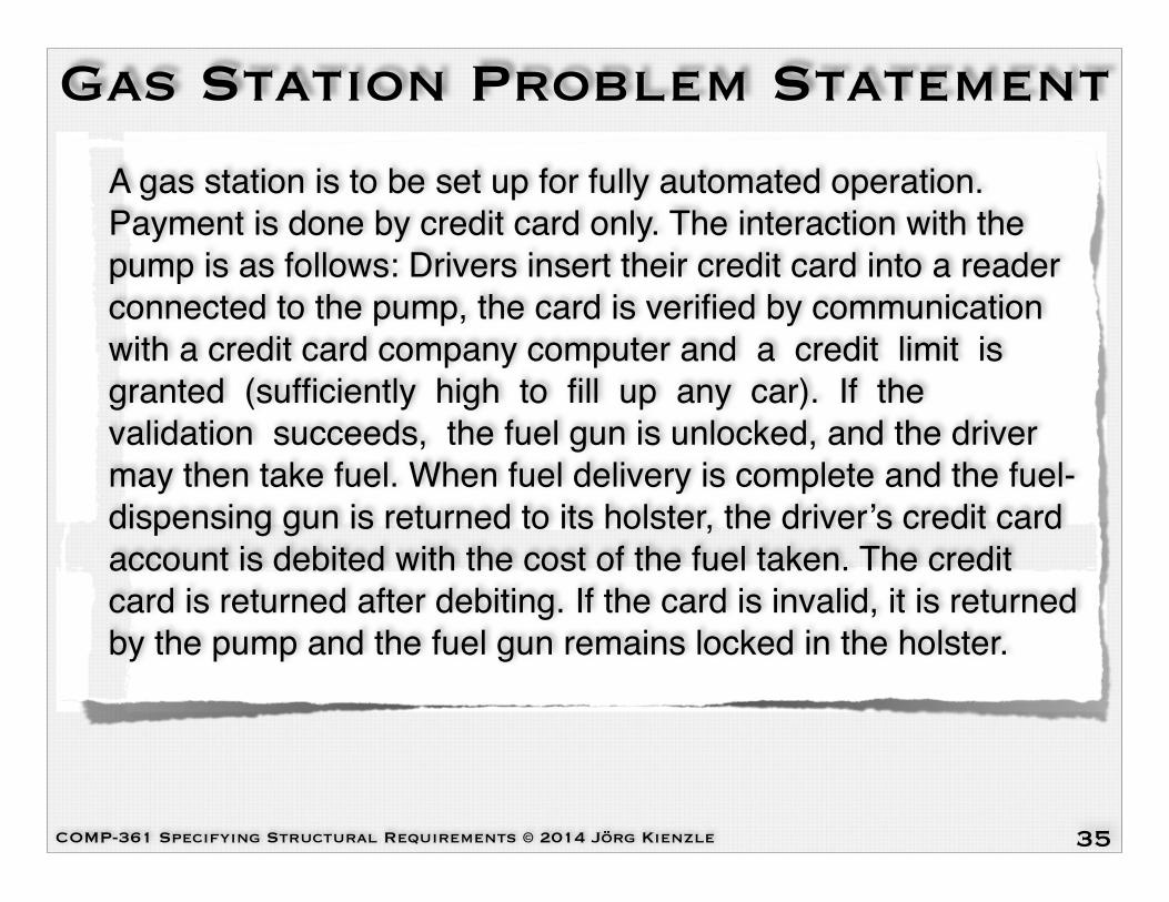
A gas station is to be set up for fully automated operation. Payment is done by credit card only. The interaction with the pump is as follows: Drivers insert their credit card into a reader connected to the pump, the card is verified by communication with a credit card company computer and a credit limit is granted (sufficiently high to fill up any car). If the validation succeeds, the fuel gun is unlocked, and the driver may then take fuel. When fuel delivery is complete and the fuel-dispensing gun is returned to its holster, the driver’s credit card account is debited with the cost of the fuel taken. The credit card is returned after debiting. If the card is invalid, it is returned by the pump and the fuel gun remains locked in the holster.
35

COMP-361 Specifying Structural Requirements © 2014 Jörg Kienzle
Gas Station Question• Elaborate an Environment Model for the gas station system. To
simplify the problem, you can assume that there is a single pump only. Here are additional requirements / tips:!• It is important that you depict all external actors that are directly connected to the system, e.g.
the Fuelgun. Indirect actors, e.g. the Driver, do not have to show up in the Environment Model.!
• You might have to “discover” additional actors / hardware that do not show up in the description. The only way your software can affect the “real world” is by sending output messages to actors. !
• Handling credit cards is part of the gas station system. There is no additional credit card machine between the gas station and the credit card company.!
• Don’t forget to add multiplicities to the actors.!• State ALL necessary input, output and time-triggered messages that are needed to provide the
functionality specified in the problem statement. Remember that all system functionality has to be triggered by an input or time-triggered message.!
• You do not have to take into account hardware and communication failures. You can safely assume reliable communication.!
• Specify message parameters for each message, together with any necessary type declarations.
36
COMP-361 Specifying Structural Requirements © 2014 Jörg Kienzle
Auction System Environment Question
• Develop an Environment Model for the Auction System. It must contain all input messages (and time-triggered messages, if needed) that are needed to provide the functionality stated in the problem statement.!
• You are also asked to give at least five output messages that can be derived from the problem statement.
39

COMP-361 Specifying Structural Requirements © 2014 Jörg Kienzle
Auction System (1)Your team has been given the responsibility to develop an online auction system that allows people to negotiate over the buying and selling of goods in the form of English-style auctions (over the Internet). The company owners want to rival the Internet auctioning sites, such as, eBay (www.ebay.com), and uBid (www.ubid.com). The innovation with this system is that it guarantees that all bids are solvent.!All potential users of the system must first enroll with the system; once enrolled they have to log on to the system for each session. Then, they are able to sell, buy, or browse the auctions available on the system. Customers have credit with the system that is used as security on each and every bid. Customers can increase their credit by asking the system to debit a certain amount from their credit card.
40
COMP-361 Specifying Structural Requirements © 2014 Jörg Kienzle
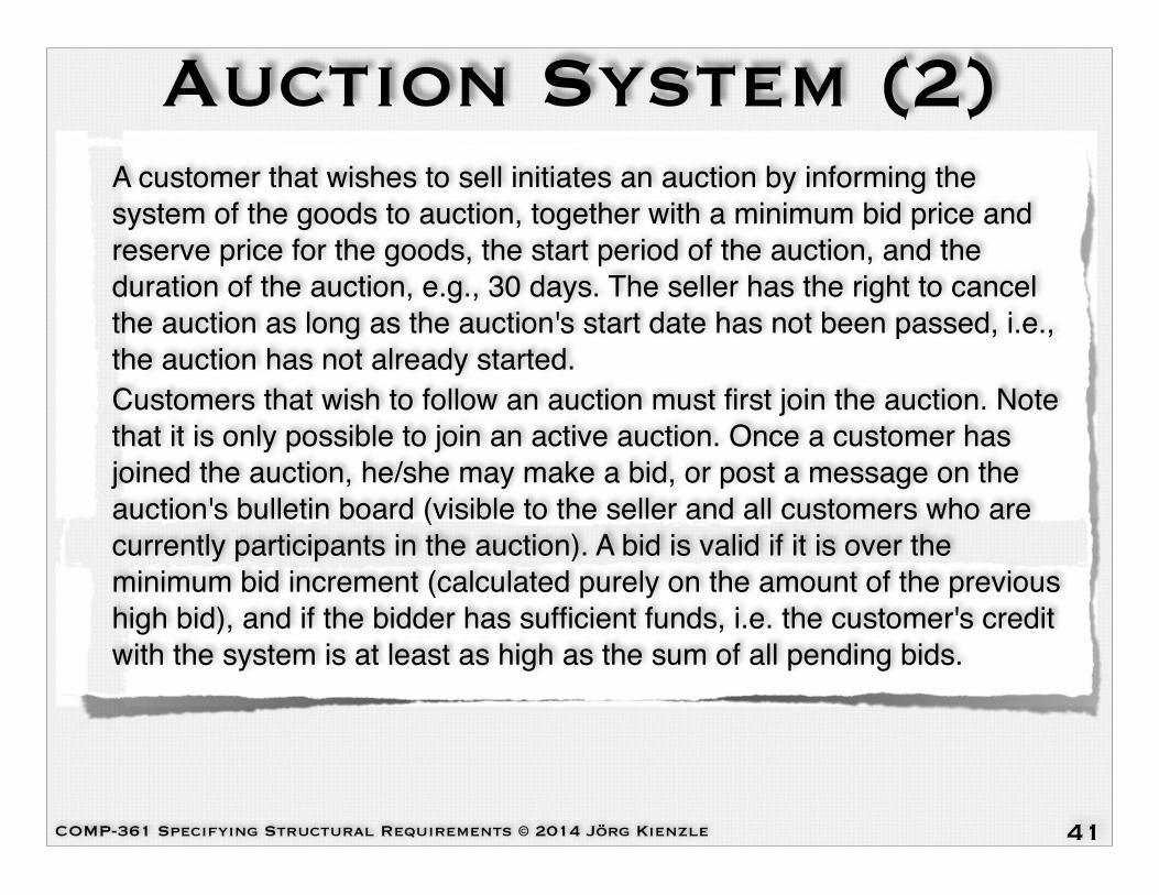
Auction System (2)A customer that wishes to sell initiates an auction by informing the system of the goods to auction, together with a minimum bid price and reserve price for the goods, the start period of the auction, and the duration of the auction, e.g., 30 days. The seller has the right to cancel the auction as long as the auction's start date has not been passed, i.e., the auction has not already started.!Customers that wish to follow an auction must first join the auction. Note that it is only possible to join an active auction. Once a customer has joined the auction, he/she may make a bid, or post a message on the auction's bulletin board (visible to the seller and all customers who are currently participants in the auction). A bid is valid if it is over the minimum bid increment (calculated purely on the amount of the previous high bid), and if the bidder has sufficient funds, i.e. the customer's credit with the system is at least as high as the sum of all pending bids.
41

COMP-361 Specifying Structural Requirements © 2014 Jörg Kienzle
Auction System (3)Bidders are allowed to place their bids until the auction closes, and place bids across as many auctions as they please. Once an auction closes, the system calculates whether the highest bid meets the reserve price given by the seller (English-style auction reserve price), and if so, the system deposits the highest bid price minus the commission taken for the auction service into the credit of the seller (credit internal with the system).!The auction system is highly concurrent — clients bidding against each other in parallel, and a client placing bids in different auctions and increasing his/her credit in parallel.
42

COMP-361 Specifying Structural Requirements © 2014 Jörg Kienzle
2. Summery-Level Use Case (1)
Use Case: Buy and Sell Goods by Auction !Scope: Auction System!Level: Summary!Intention in Context: The intention of the User is to buy and sell goods by auctions over time.!Multiplicity: Multiple users can interact with the auction system concurrently. A User can be involved in multiple auctions at any one time.!Primary Actor: User (becomes Customer, once s/he has identified him/herself with the System)
43

COMP-361 Specifying Structural Requirements © 2014 Jörg Kienzle
2. Summery-Level Use Case (2)Main Success Scenario:!All Users must first enrol with the System before they have the right to use the system!1. User enrols with System, providing System with registration information.!Steps 2-5 can be repeated many times.!2. User identifies him/herself to System.!3. System presents Customer with a welcome message.!The user-goal level use cases of step 4 can be performed in parallel and individually repeated. A customer may bid and sell in many auctions at any one time.!4. Customer increases credit with System!! or Customer buys an item on auction!! or Customer sells an item by auction!5. Customer exits System.!6. Customer requests to cancel his/her enrollment. !Extensions:!3a. System fails to identify User; use case continues at step 2.
44

COMP-361 Specifying Structural Requirements © 2014 Jörg Kienzle
3. Auction System Use Case Diagram
45
Auction System
<<include>>
Customer
Enrol
<<include>>
Close Auction
<<include>>
<<include>>
Search for Auction Item
<<in
clud
e>>
Sell Item by Auction
Buy Item on Auction
Identify<<include>>
TransferCredit
<<in
clud
e>>
<<include>>
Buy and Sell Goods by Auction
Credit CardCompany
*
*
0..*
0..*

COMP-361 Specifying Structural Requirements © 2014 Jörg Kienzle
4. Buy Item Use Case (1)Use Case: Buy Item on Auction !Scope: Auction System!Level: User Goal !Intention in Context: The intention of the Customer is to follow the auction, which may then evolve into an intention to buy an item by auction, i.e., he/she may then choose to bid for an item.!Multiplicity: Several Customers can place bid simultaneously. A given Customer may bid in many different auctions at any one time.!Primary Actor: Customer !Precondition: The Customer has already identified her / himself to the System
46

COMP-361 Specifying Structural Requirements © 2014 Jörg Kienzle
4. Buy Item Use Case (2)Main Success Scenario:!Customer may leave the auction and come back again later to look at the progress of the auction, without effect on the auction; in this case, the Customer is required to join the auction again. !1. Customer searches for an item under auction. !2. Customer requests System to join the auction of the item. !3. System presents a view of the auction to Customer. !Steps 4-5 can be repeated according to the intentions and bidding policy of the Customer.!4. Customer makes a bid on the item to System. !5. System validates the bid. !6. System closes the auction with a winning bid by Customer.
47
COMP-361 Specifying Structural Requirements © 2014 Jörg Kienzle
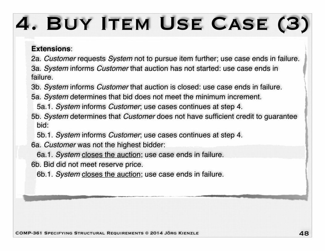
4. Buy Item Use Case (3)Extensions:!2a. Customer requests System not to pursue item further; use case ends in failure.!3a. System informs Customer that auction has not started: use case ends in failure.!3b. System informs Customer that auction is closed: use case ends in failure.!5a. System determines that bid does not meet the minimum increment.!! 5a.1. System informs Customer; use cases continues at step 4.!5b. System determines that Customer does not have sufficient credit to guarantee! bid:!! 5b.1. System informs Customer; use cases continues at step 4.!6a. Customer was not the highest bidder:!! 6a.1. System closes the auction; use case ends in failure.!6b. Bid did not meet reserve price.!! 6b.1. System closes the auction; use case ends in failure.!
48

COMP-361 Specifying Structural Requirements © 2014 Jörg Kienzle
Elevator Environment and Concept Model
• You are to devise the Environment Model and the Concept Model for the Elevator system based on the Use Case Model. Remember that:!• There is only one elevator cabin, which travels between the floors.!• There is a single button on each floor to call the lift.!• Inside the elevator cabin, there is a series of buttons, one for each floor.!• Requests are definitive, i.e., they cannot be cancelled, and they persist; thus they should
eventually be serviced.!• The arrival of the cabin at a floor is detected by a sensor.!• The system may ask the elevator to go up, go down or stop. In this example, we assume
that the elevator's braking distance is negligible.!• The system may ask the elevator to open its door. The system will receive a notification
when the door is closed. This simulates the activity of letting people on and off at each floor.!
• The door closes automatically after a predefined amount of time. However, neither this function of the elevator nor the protection associated with the door closing (stopping it from squashing people) are part of the system to realize.
50
COMP-361 Specifying Structural Requirements © 2014 Jörg Kienzle
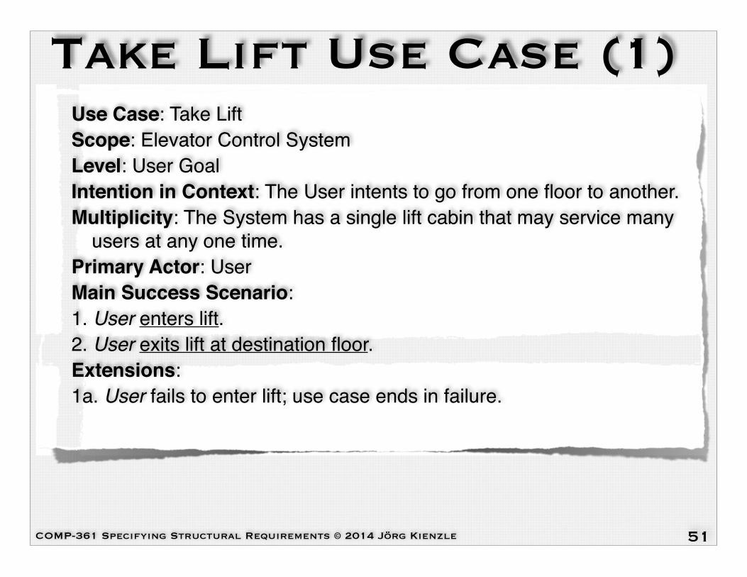
Take Lift Use Case (1) Use Case: Take Lift!Scope: Elevator Control System!Level: User Goal!Intention in Context: The User intents to go from one floor to another.!Multiplicity: The System has a single lift cabin that may service many
users at any one time.!Primary Actor: User!Main Success Scenario:!1. User enters lift.!2. User exits lift at destination floor.!Extensions:!1a. User fails to enter lift; use case ends in failure.!
51

COMP-361 Specifying Structural Requirements © 2014 Jörg Kienzle
Enter Life Use Case (1) Use Case: Enter Lift!Scope: Elevator Control System!Level: Subfunction!Intention in Context: The User intends to enter the cabin at a certain floor.!Primary Actor: User!Secondary Actors: Floor Sensor, Motor, Door!Main Success Scenario:!1. User requests System for lift;!2. System acknowledges request to User.!3. System requests Motor to go to source floor.!Step 4 is repeated until System determines that the source floor of the User has been reached!4. Floor Sensor informs System that lift has reached a certain floor.!5. System requests Motor to stop;!6. Motor informs System that lift is stopped.!7. System requests Door to open;!User enters lift at source floor.!
52

COMP-361 Specifying Structural Requirements © 2014 Jörg Kienzle
Enter Life Use Case (2) Extensions:!3a. System determines that another request has priority:! 3a.1. System schedules the request; use case continues at
step 2.!3b. System determines that the cabin is already at the
requested floor. 3b.1a System determines that the door is open; use case ends in success.!
3b.1b System determines that the door is closed; use case continues at step 7.!
53

COMP-361 Specifying Structural Requirements © 2014 Jörg Kienzle
Exit Life Use Case (1) Use Case: Exit Lift!Scope: Elevator Control System!Level: Subfunction!Intention in Context: The User intends to leave the cabin at a certain floor.!Primary Actor: User!Secondary Actors: Floor Sensor, Motor, Door!Main Success Scenario:!Steps 1 and 2 can happen in any order.!1. User requests System to go to a floor.!2. System acknowledges request to User.!3. Door informs System that it is closed.!4. System requests Motor to go to destination floor.!Step 5 is repeated until System determines that the destination floor of the User has been reached.!5. Floor Sensor informs System that lift has reached a certain floor.!6. System requests Motor to stop.!7. Motor informs System that lift is stopped.!8. System requests Door to open.!9. User exits lift at destination floor.
54

COMP-361 Specifying Structural Requirements © 2014 Jörg Kienzle
Extensions:!(3-5)||a. User requests System to go to a different floor;! (3-5)||a.1 System schedules the request; use case continues
at the same step.!4a. System determines that another request has priority.! 4a.1. System schedules the request; use case continues at
step 4.!9a. System determines that there are additional requests
pending; use case continues at step 3.!
Exit Lift Use Case (2)
55