CSIT 220 (Blum)1 IP Datagram Based on Chapter 20 of Computer Networks and Internets (Comer)

COMP 3331/9331: Computer Networks and
Applications
Week 7 Network Layer
Chapter 4, Sections:4.1 – 4.3
Assignment 1
v Hard deadline: NO EXTENSIONS v IMPORTANT: Make sure you test your program
on CSE machines as per the demo setup v Demonstration Schedule for Week 8 is linked to
assignment page § YOU MUST ATTEND YOUR ALLOCATED SLOT
v MONDAY: PUBLIC HOLIDAY § Demo in Week 9 § Monday lab schedule will be pushed back by one week
2 Network Layer
3
Chapter 4: network layer
Our goals: v understand principles behind network layer
services: § network layer service models § forwarding versus routing § how a router works § routing (path selection) § broadcast, multicast
v instantiation, implementation in the Internet
Network Layer
4
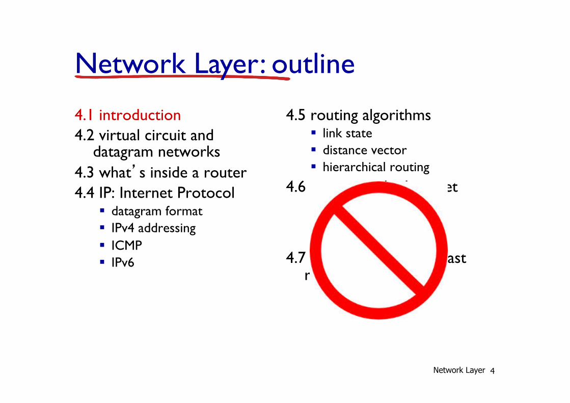
4.1 introduction 4.2 virtual circuit and
datagram networks 4.3 what’s inside a router 4.4 IP: Internet Protocol
§ datagram format § IPv4 addressing § ICMP § IPv6
4.5 routing algorithms § link state § distance vector § hierarchical routing
4.6 routing in the Internet § RIP § OSPF § BGP
4.7 broadcast and multicast routing
Network Layer: outline
Network Layer
Some background
v 1968: DARPAnet/ARPAnet (precursor to Internet) § (Defense) Advanced Research Projects Agency Network
v Mid 1970’s: new networks emerge § SATNet, Packet Radio, Ethernet § All “islands” to themselves – didn’t work together
v Big question: How to connect these networks?
5 Network Layer
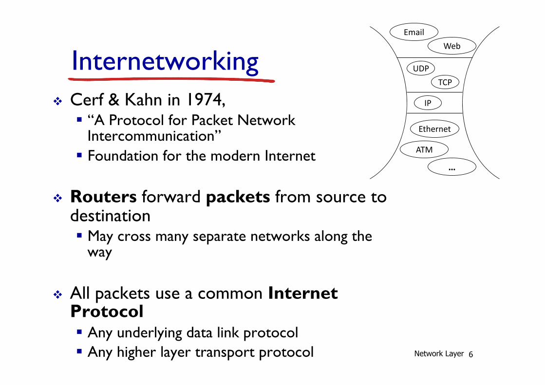
Internetworking v Cerf & Kahn in 1974,
§ “A Protocol for Packet Network Intercommunication”
§ Foundation for the modern Internet
v Routers forward packets from source to destination § May cross many separate networks along the
way
v All packets use a common Internet Protocol § Any underlying data link protocol § Any higher layer transport protocol 6 Network Layer
Internet Protocol Stack
• Application: Email, Web, … • Transport: TCP, UDP, … • Network: IP • Link: Ethernet, WiFi, ATM, … • Physical: copper, fiber, air, …
• “Hourglass” model, “thin waist”, “narrow waist”
IP
UDP TCP
Ethernet
ATM
…
Email Web
7
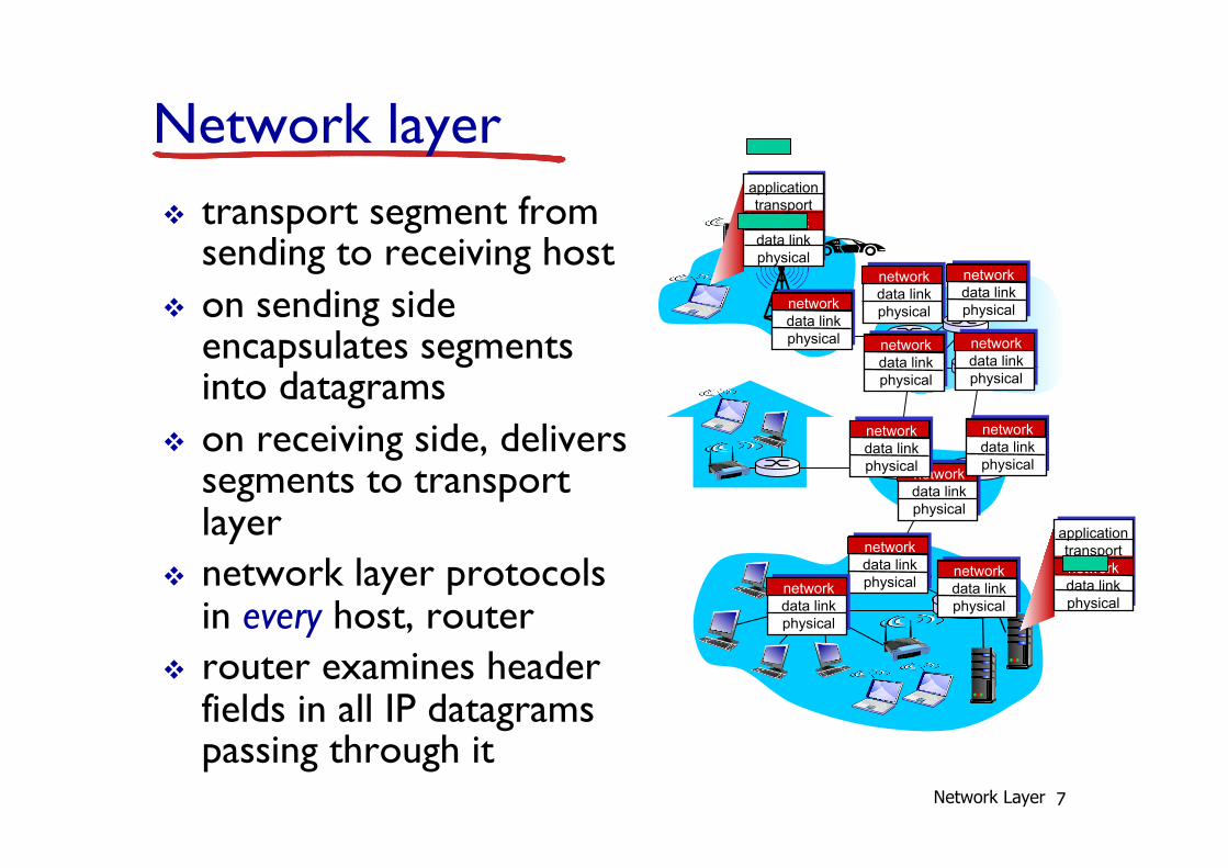
Network layer v transport segment from
sending to receiving host v on sending side
encapsulates segments into datagrams
v on receiving side, delivers segments to transport layer
v network layer protocols in every host, router
v router examines header fields in all IP datagrams passing through it
application transport network data link physical
application transport network data link physical
network data link physical
network data link physical
network data link physical
network data link physical
network data link physical
network data link physical
network data link physical
network data link physical
network data link physical
network data link physical
network data link physical
Network Layer
8
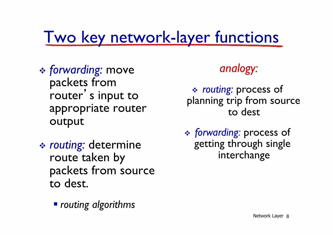
Two key network-layer functions
v forwarding: move packets from router’s input to appropriate router output
v routing: determine route taken by packets from source to dest.
§ routing algorithms
analogy:
v routing: process of planning trip from source
to dest
v forwarding: process of getting through single
interchange
Network Layer
Quiz: When should a router perform routing? Fowarding
A: Do both when a packet arrives B: Route in advance, forward when a packet arrives C: Forward in advance, route when a packet arrives D: Do both in advance E: Some other combination
9 Network Layer
10
1
2 3
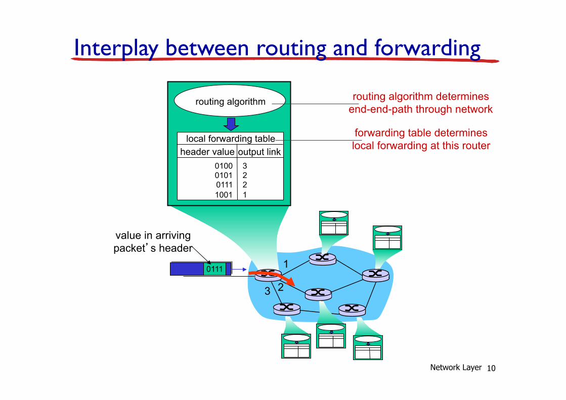
0111
value in arriving packet’s header
routing algorithm
local forwarding table header value output link
0100 0101 0111 1001
3 2 2 1
Interplay between routing and forwarding
routing algorithm determines end-end-path through network
forwarding table determines local forwarding at this router
Network Layer
11
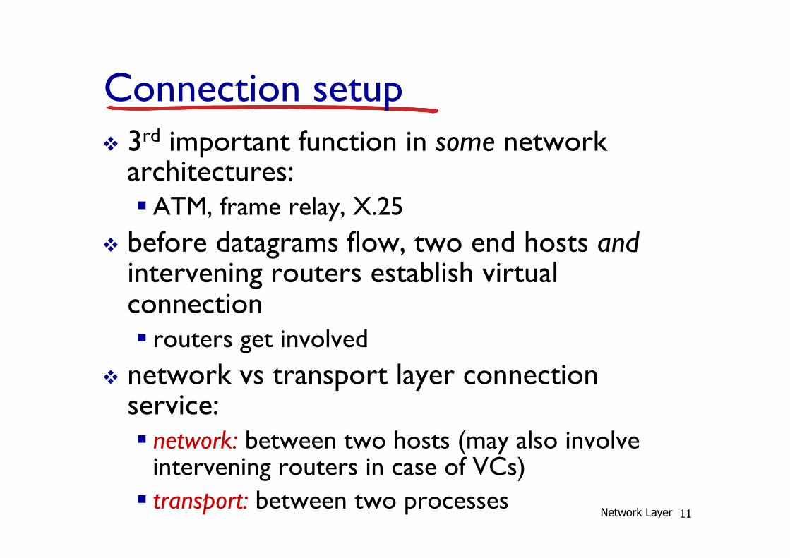
Connection setup v 3rd important function in some network
architectures: § ATM, frame relay, X.25
v before datagrams flow, two end hosts and intervening routers establish virtual connection § routers get involved
v network vs transport layer connection service: § network: between two hosts (may also involve
intervening routers in case of VCs) § transport: between two processes
Network Layer
12
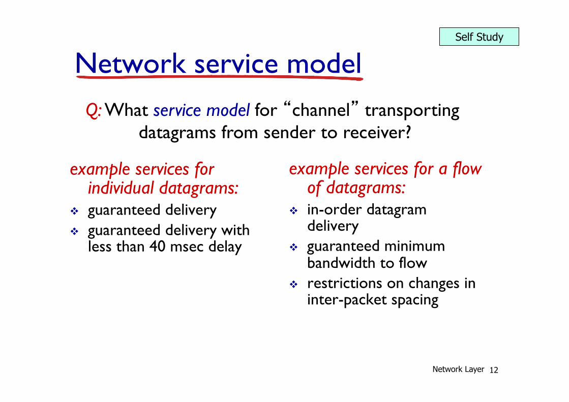
Network service model Q: What service model for “channel” transporting
datagrams from sender to receiver?
example services for individual datagrams:
v guaranteed delivery v guaranteed delivery with
less than 40 msec delay
example services for a flow of datagrams:
v in-order datagram delivery
v guaranteed minimum bandwidth to flow
v restrictions on changes in inter-packet spacing
Network Layer
Self Study
13
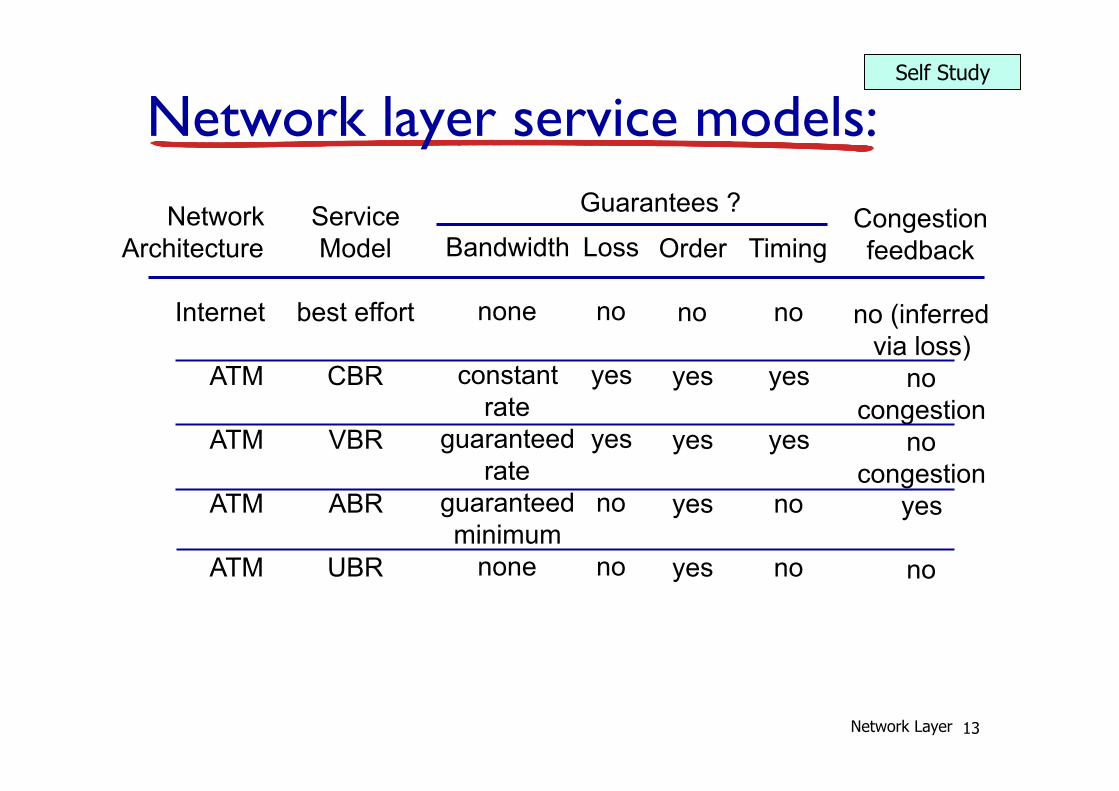
Network layer service models: Network
Architecture
Internet
ATM
ATM
ATM
ATM
Service Model
best effort
CBR
VBR
ABR
UBR
Bandwidth
none
constant rate
guaranteed rate
guaranteed minimum
none
Loss
no
yes
yes
no
no
Order
no
yes
yes
yes
yes
Timing
no
yes
yes
no
no
Congestion feedback
no (inferred
via loss) no
congestion no
congestion yes
no
Guarantees ?
Network Layer
Self Study
14
4.1 introduction 4.2 virtual circuit and
datagram networks 4.3 what’s inside a router 4.4 IP: Internet Protocol
§ datagram format § IPv4 addressing § ICMP § IPv6
4.5 routing algorithms § link state § distance vector § hierarchical routing
4.6 routing in the Internet § RIP § OSPF § BGP
4.7 broadcast and multicast routing
Network Layer: outline
Network Layer
15
Connection, connection-less service
v datagram network provides network-layer connectionless service
v virtual-circuit network provides network-layer connection service
v analogous to TCP/UDP connecton-oriented / connectionless transport-layer services, but: § service: host-to-host § no choice: network provides one or the other § implementation: in network core
Network Layer
16
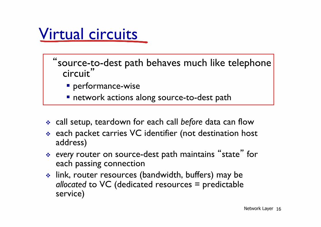
Virtual circuits
v call setup, teardown for each call before data can flow v each packet carries VC identifier (not destination host
address) v every router on source-dest path maintains “state” for
each passing connection v link, router resources (bandwidth, buffers) may be
allocated to VC (dedicated resources = predictable service)
“source-to-dest path behaves much like telephone circuit” § performance-wise § network actions along source-to-dest path
Network Layer
17
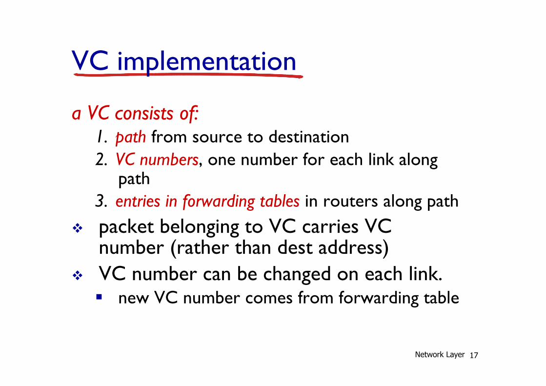
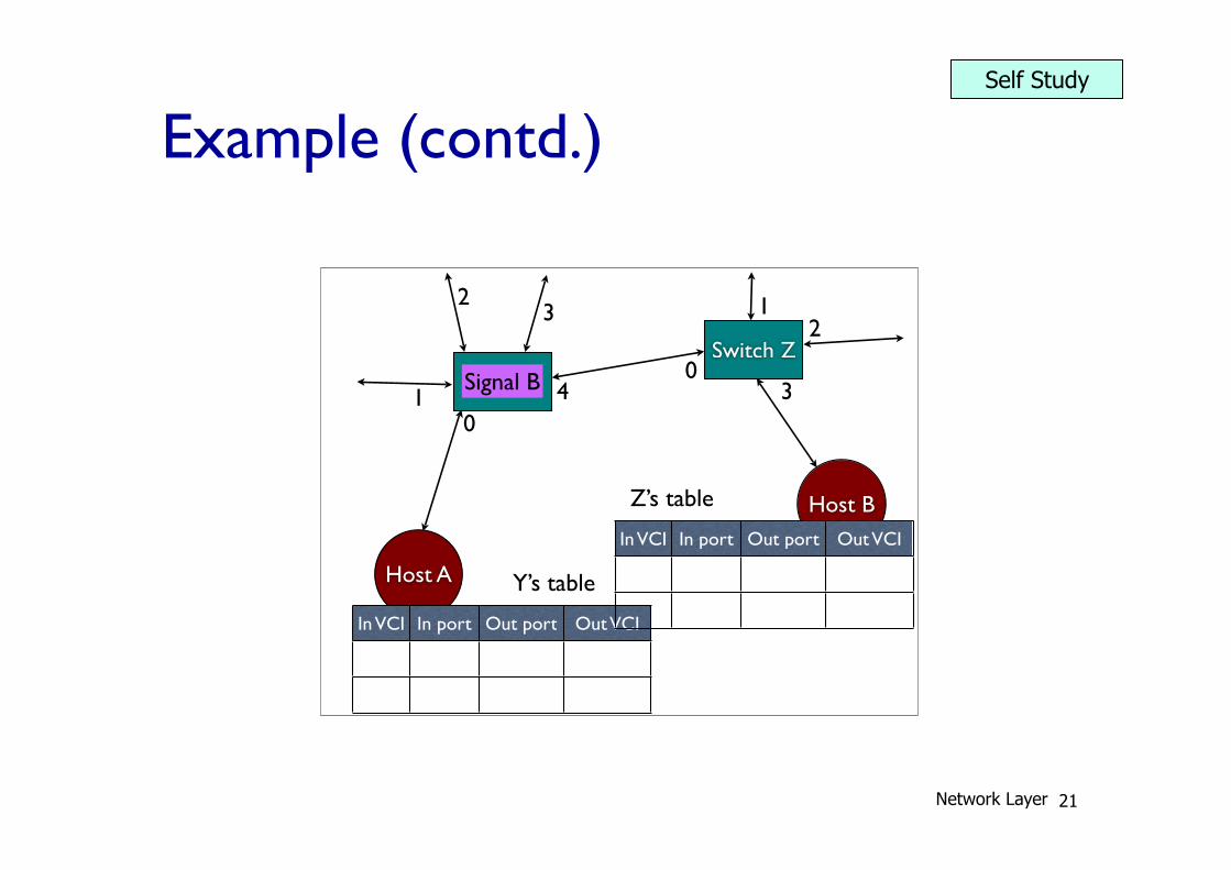
VC implementation
a VC consists of: 1. path from source to destination 2. VC numbers, one number for each link along
path 3. entries in forwarding tables in routers along path
v packet belonging to VC carries VC number (rather than dest address)
v VC number can be changed on each link. § new VC number comes from forwarding table
Network Layer
18
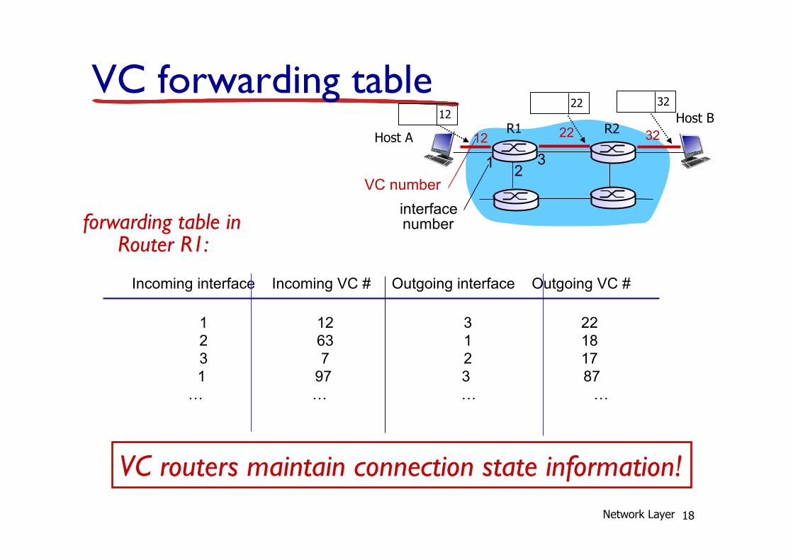
VC forwarding table 12 22 32
1 2 3
VC number interface number
Incoming interface Incoming VC # Outgoing interface Outgoing VC #
1 12 3 22 2 63 1 18 3 7 2 17 1 97 3 87 … … … …
forwarding table in Router R1:
VC routers maintain connection state information!
12 22 32
R1 R2 Host A
Host B
Network Layer
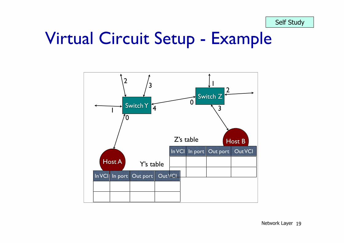
Virtual Circuit Setup - Example
19
CS357b 91
ATM Adaptation Layer (AAL)
! ATM Adaptation Layer (AAL): “adapts” upper layers (IP or native ATM applications) to ATM layer below
! AAL present only in end systems, not in switches
! AAL layer segment (header/trai ler f ields, data) fragmented across multiple ATM cells
" analogy: TCP segment in many IP packets
CS357b 92
ATM Adaptation Layer (AAL) [more]
Different versions of AAL layers, depending on ATM service class:
! AAL1: for CBR (Constant Bit Rate) services, e.g. circuit emulation
! AAL2: for VBR (Variable Bit Rate) services, e.g., MPEG video
! AAL5: for data (eg, IP datagrams)
AAL PDU
ATM cell
User data
CS357b 93
ATM LayerService: transport cells across ATM network
! analogous to IP network layer
! very different services than IP network layer
Network
Architecture
Internet
ATM
ATM
ATM
ATM
Service
Model
best effort
CBR
VBR
ABR
UBR
Bandwidth
none
constant
rate
guaranteed
rate
guaranteed
minimumnone
Loss
no
yes
yes
no
no
Order
no
yes
yes
yes
yes
Timing
no
yes
yes
no
no
Congestion
feedback
no (inferred
via loss)
no
congestion
no
congestion
yes
no
Guarantees ?
CS357b 94
ATM Layer: Virtual Circuits
! VC transport: cells carried on VC from source to dest
" call setup, teardown for each call be fore data can flow
" each packet carries VC identi f ier (not dest inat ion ID)
" every switch on source-dest path maintain “state” for each
passing connection
" link,switch resources (bandwidth, buffers) may be allocated to
VC: to get circuit-l ike perf.
! Permanent VCs (PVCs)
" long lasting connections
" typically: “permanent” route between to IP routers
! Switched VCs (SVC):
" dynamically set up on per-call basis
Host A
Host B
Switch Y
Switch Z
01
23
40
12
3
In VCI In port Out port Out VCI
Y’s table
In VCI In port Out port Out VCI
Z’s table
01
23
40
12
3
Y’s table
Z’s table
Signal B
Network Layer
Self Study
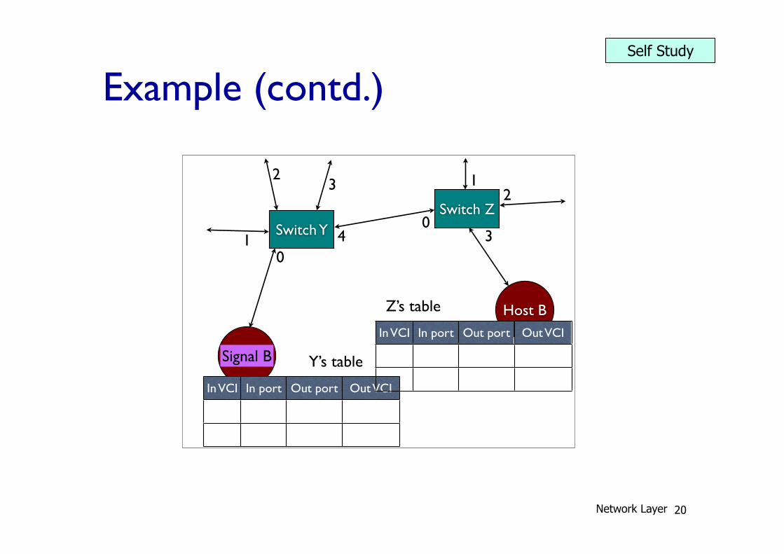
Example (contd.)
20
CS357b 91
ATM Adaptation Layer (AAL)
! ATM Adaptation Layer (AAL): “adapts” upper layers (IP or native ATM applications) to ATM layer below
! AAL present only in end systems, not in switches
! AAL layer segment (header/trai ler f ields, data) fragmented across multiple ATM cells
" analogy: TCP segment in many IP packets
CS357b 92
ATM Adaptation Layer (AAL) [more]
Different versions of AAL layers, depending on ATM service class:
! AAL1: for CBR (Constant Bit Rate) services, e.g. circuit emulation
! AAL2: for VBR (Variable Bit Rate) services, e.g., MPEG video
! AAL5: for data (eg, IP datagrams)
AAL PDU
ATM cell
User data
CS357b 93
ATM LayerService: transport cells across ATM network
! analogous to IP network layer
! very different services than IP network layer
Network
Architecture
Internet
ATM
ATM
ATM
ATM
Service
Model
best effort
CBR
VBR
ABR
UBR
Bandwidth
none
constant
rate
guaranteed
rate
guaranteed
minimumnone
Loss
no
yes
yes
no
no
Order
no
yes
yes
yes
yes
Timing
no
yes
yes
no
no
Congestion
feedback
no (inferred
via loss)
no
congestion
no
congestion
yes
no
Guarantees ?
CS357b 94
ATM Layer: Virtual Circuits
! VC transport: cells carried on VC from source to dest
" call setup, teardown for each call be fore data can flow
" each packet carries VC identi f ier (not dest inat ion ID)
" every switch on source-dest path maintain “state” for each
passing connection
" link,switch resources (bandwidth, buffers) may be allocated to
VC: to get circuit-l ike perf.
! Permanent VCs (PVCs)
" long lasting connections
" typically: “permanent” route between to IP routers
! Switched VCs (SVC):
" dynamically set up on per-call basis
01
23
40
12
3
Y’s table
Z’s table
Host A
Host B
Switch Y
Switch Z
01
23
40
12
3
In VCI In port Out port Out VCI
Y’s table
In VCI In port Out port Out VCI
Z’s table
Signal B
Network Layer
Self Study
Example (contd.)
21
Host A
Host B
Switch Y
Switch Z
01
23
40
12
3
In VCI In port Out port Out VCI
Y’s table
In VCI In port Out port Out VCI
Z’s table
Signal B
01
23
40
12
3
3 0 4
Y’s table
Z’s table
Signal B
01
23
40
12
3
3 0 4
Y’s table
Z’s table
Signal B
01
23
40
12
3
3 0 4
Y’s table 12 0 3
Z’s table
Signal B
01
23
40
12
3
3 0 4
Y’s table 12 0 3
Z’s table Signal B
01
23
40
12
3
3 0 4
Y’s table 12 0 3
Z’s table ACK 7
Network Layer
Self Study
Example (contd.)
22
01
23
40
12
3
Y’s table
Z’s table
Signal B
Host A
Host B
Switch Y
Switch Z
01
23
40
12
3
In VCI In port Out port Out VCI
3 0 4
Y’s table
In VCI In port Out port Out VCI
Z’s table
Signal B
01
23
40
12
3
3 0 4
Y’s table
Z’s table
Signal B
01
23
40
12
3
3 0 4
Y’s table 12 0 3
Z’s table
Signal B
01
23
40
12
3
3 0 4
Y’s table 12 0 3
Z’s table Signal B
01
23
40
12
3
3 0 4
Y’s table 12 0 3
Z’s table ACK 7
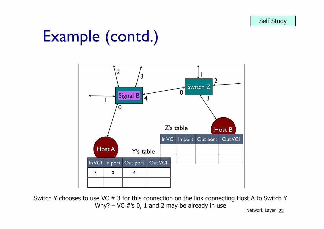
Switch Y chooses to use VC # 3 for this connection on the link connecting Host A to Switch Y Why? – VC #’s 0, 1 and 2 may be already in use
Network Layer
Self Study

Example (contd.)
23
01
23
40
12
3
Y’s table
Z’s table
Signal B
01
23
40
12
3
3 0 4
Y’s table
Z’s table
Signal B
Host A
Host B
Switch Y
Switch Z
01
23
40
12
3
In VCI In port Out port Out VCI
3 0 4
Y’s table
In VCI In port Out port Out VCI
Z’s table
Signal B
01
23
40
12
3
3 0 4
Y’s table 12 0 3
Z’s table
Signal B
01
23
40
12
3
3 0 4
Y’s table 12 0 3
Z’s table Signal B
01
23
40
12
3
3 0 4
Y’s table 12 0 3
Z’s table ACK 7
Network Layer
Self Study
Example (contd.)
48
01
23
40
12
3
Y’s table
Z’s table
Signal B
01
23
40
12
3
3 0 4
Y’s table
Z’s table
Signal B
01
23
40
12
3
3 0 4
Y’s table
Z’s table
Signal B
Host A
Host B
Switch Y
Switch Z
01
23
40
12
3
In VCI In port Out port Out VCI
3 0 4
Y’s table
In VCI In port Out port Out VCI
12 0 3
Z’s table
Signal B
01
23
40
12
3
3 0 4
Y’s table 12 0 3
Z’s table Signal B
01
23
40
12
3
3 0 4
Y’s table 12 0 3
Z’s table ACK 7
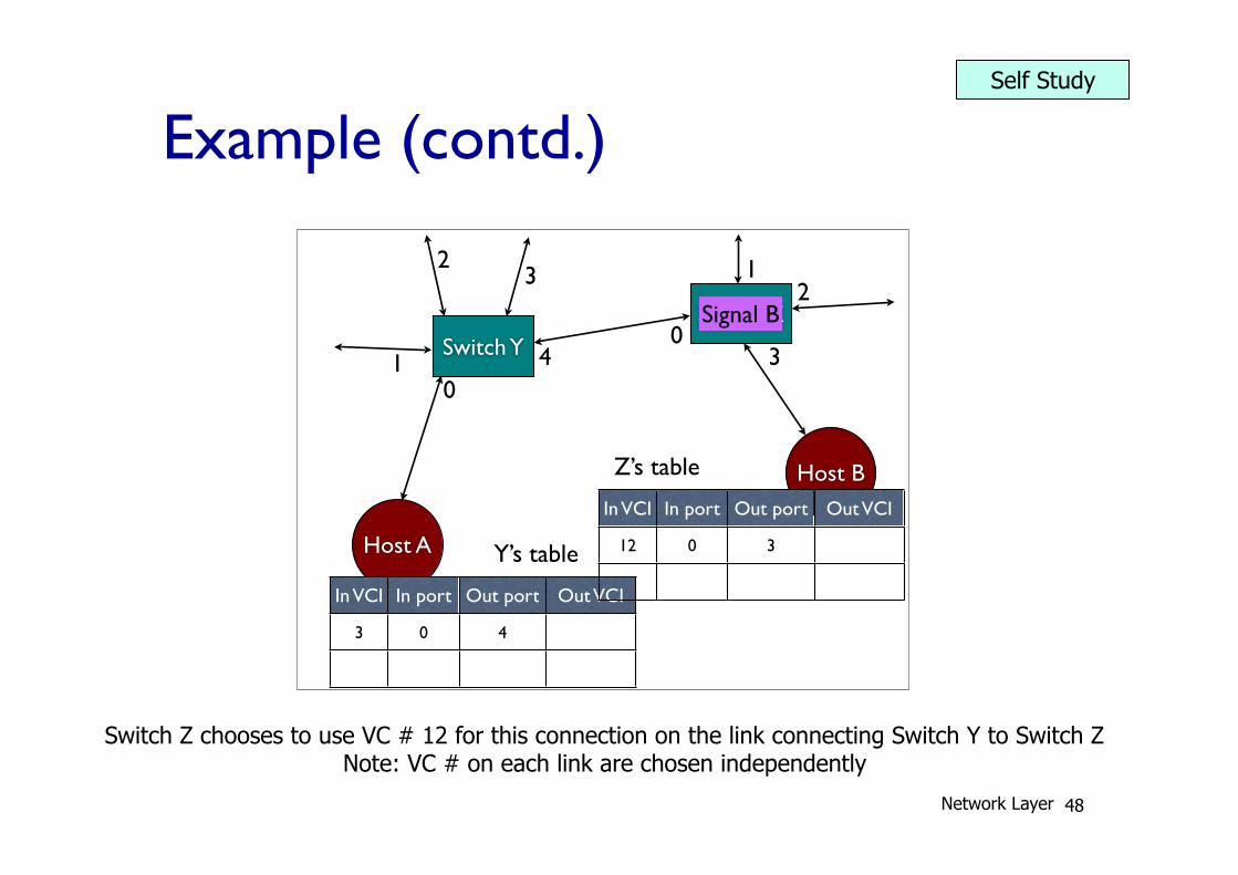
Switch Z chooses to use VC # 12 for this connection on the link connecting Switch Y to Switch Z Note: VC # on each link are chosen independently
Network Layer
Self Study
Example (contd.)
25
01
23
40
12
3
Y’s table
Z’s table
Signal B
01
23
40
12
3
3 0 4
Y’s table
Z’s table
Signal B
01
23
40
12
3
3 0 4
Y’s table
Z’s table
Signal B
01
23
40
12
3
3 0 4
Y’s table 12 0 3
Z’s table
Signal B
Host A
Host B
Switch Y
Switch Z
01
23
40
12
3
In VCI In port Out port Out VCI
3 0 4
Y’s table
In VCI In port Out port Out VCI
12 0 3
Z’s table Signal B
01
23
40
12
3
3 0 4
Y’s table 12 0 3
Z’s table ACK 7
Network Layer
Self Study
Example (contd.)
26
01
23
40
12
3
Y’s table
Z’s table
Signal B
01
23
40
12
3
3 0 4
Y’s table
Z’s table
Signal B
01
23
40
12
3
3 0 4
Y’s table
Z’s table
Signal B
01
23
40
12
3
3 0 4
Y’s table 12 0 3
Z’s table
Signal B
01
23
40
12
3
3 0 4
Y’s table 12 0 3
Z’s table Signal B
Host A
Host B
Switch Y
Switch Z
01
23
40
12
3
In VCI In port Out port Out VCI
3 0 4
Y’s table
In VCI In port Out port Out VCI
12 0 3
Z’s table ACK 7
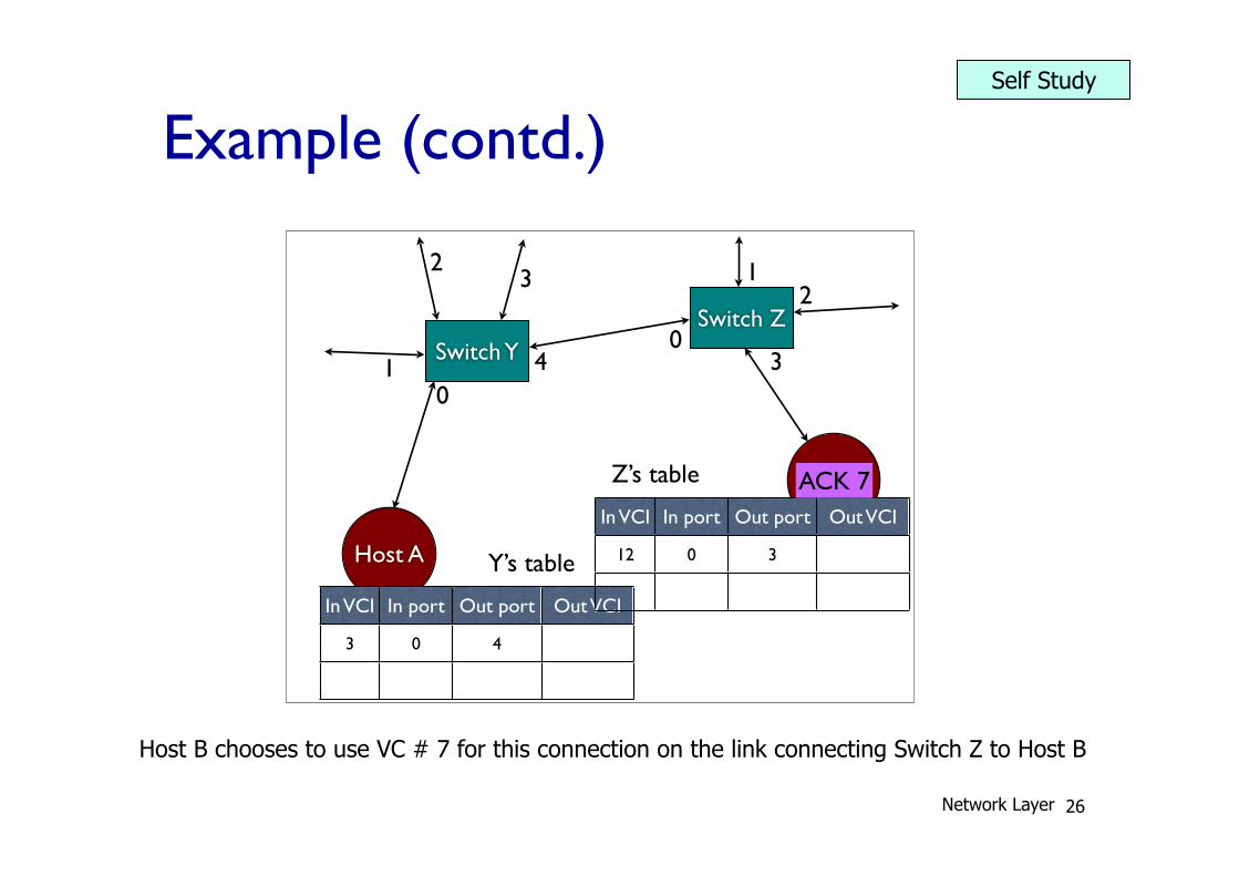
Host B chooses to use VC # 7 for this connection on the link connecting Switch Z to Host B
Network Layer
Self Study
Example (contd.)
27
Host A
Host B
Switch Y
Switch Z
01
23
40
12
3
In VCI In port Out port Out VCI
3 0 4
Y’s table
In VCI In port Out port Out VCI
12 0 3
Z’s table
ACK 7
01
23
40
12
3
3 0 4
Y’s table 12 0 3 7
Z’s table
ACK 12
01
23
40
12
3
3 0 4
Y’s table 12 0 3 7
Z’s table
ACK 12
01
23
40
12
3
3 0 4 12
Y’s table 12 0 3 7
Z’s table
ACK 3
01
23
40
12
3
3 0 4 12
Y’s table 12 0 3 7
Z’s table
ACK 3
01
23
40
12
3
3 0 4 12
Y’s table 12 0 3 7
Z’s table
I love you! 3
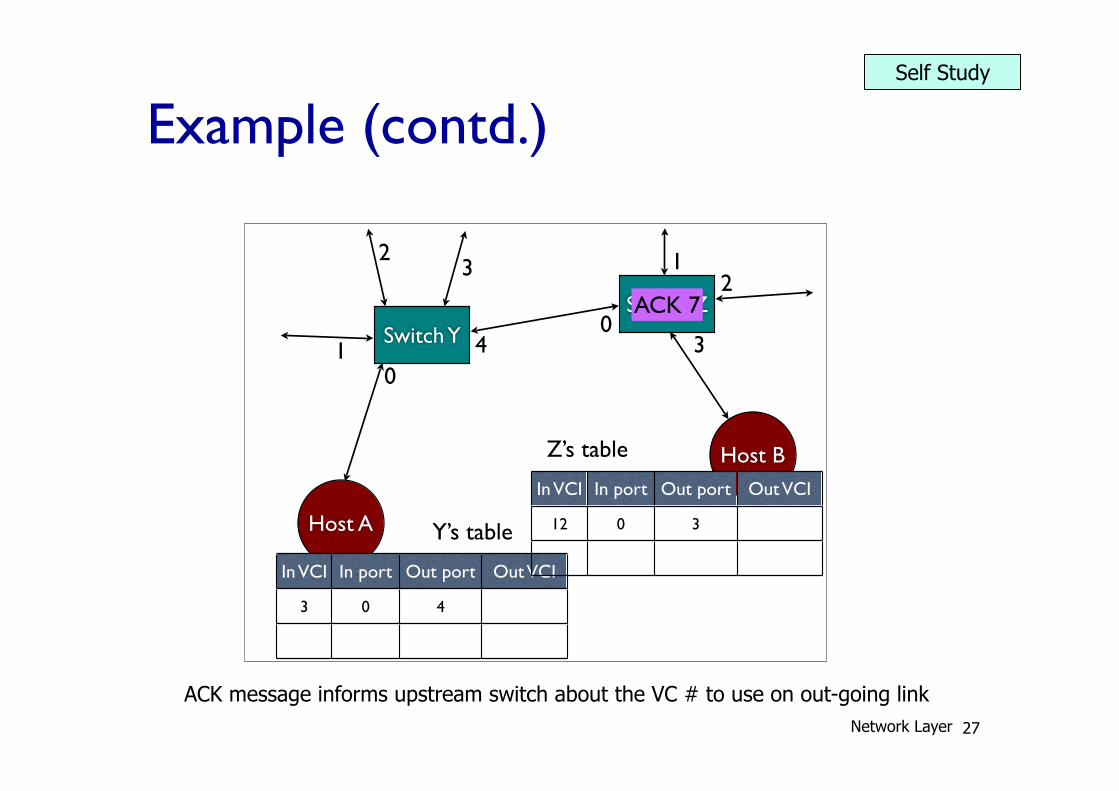
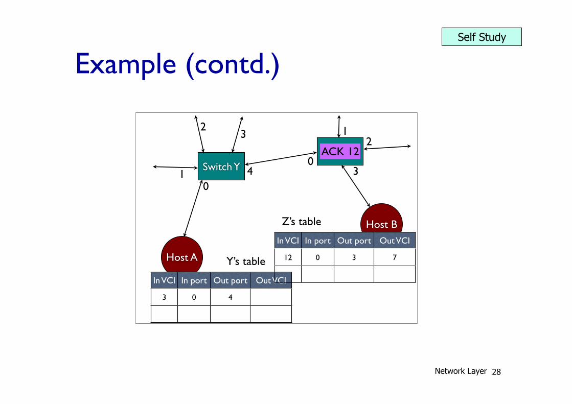
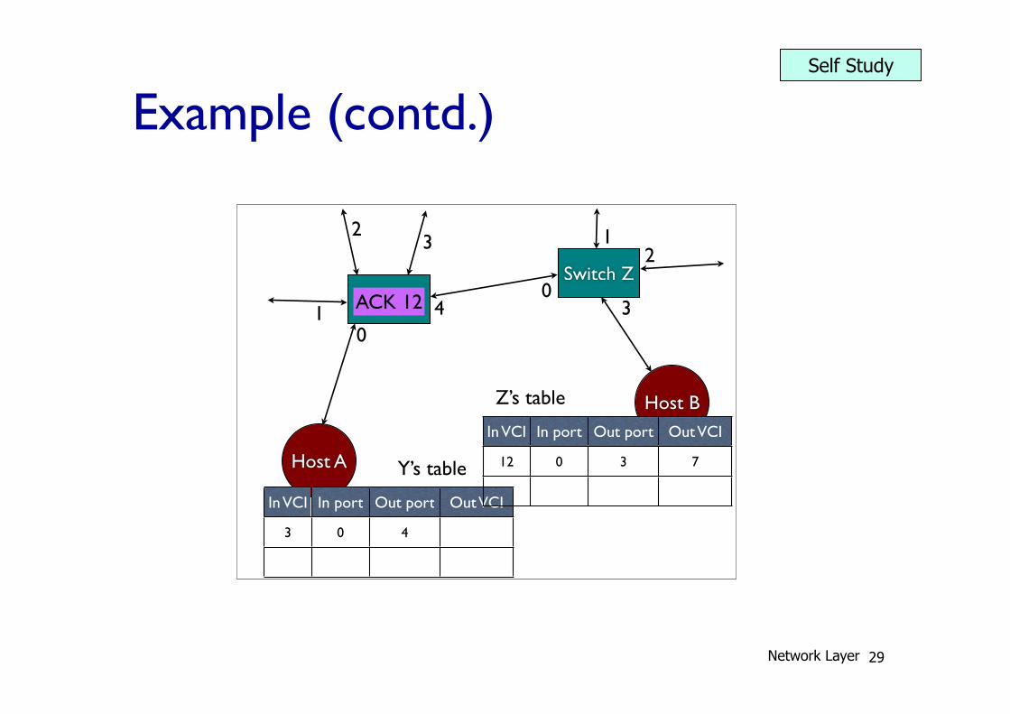
ACK message informs upstream switch about the VC # to use on out-going link Network Layer
Self Study
Example (contd.)
28
01
23
40
12
3
3 0 4
Y’s table 12 0 3
Z’s table
ACK 7
Host A
Host B
Switch Y
Switch Z
01
23
40
12
3
In VCI In port Out port Out VCI
3 0 4
Y’s table
In VCI In port Out port Out VCI
12 0 3 7
Z’s table
ACK 12
01
23
40
12
3
3 0 4
Y’s table 12 0 3 7
Z’s table
ACK 12
01
23
40
12
3
3 0 4 12
Y’s table 12 0 3 7
Z’s table
ACK 3
01
23
40
12
3
3 0 4 12
Y’s table 12 0 3 7
Z’s table
ACK 3
01
23
40
12
3
3 0 4 12
Y’s table 12 0 3 7
Z’s table
I love you! 3
Network Layer
Self Study
Example (contd.)
29
01
23
40
12
3
3 0 4
Y’s table 12 0 3
Z’s table
ACK 7
01
23
40
12
3
3 0 4
Y’s table 12 0 3 7
Z’s table
ACK 12
Host A
Host B
Switch Y
Switch Z
01
23
40
12
3
In VCI In port Out port Out VCI
3 0 4
Y’s table
In VCI In port Out port Out VCI
12 0 3 7
Z’s table
ACK 12
01
23
40
12
3
3 0 4 12
Y’s table 12 0 3 7
Z’s table
ACK 3
01
23
40
12
3
3 0 4 12
Y’s table 12 0 3 7
Z’s table
ACK 3
01
23
40
12
3
3 0 4 12
Y’s table 12 0 3 7
Z’s table
I love you! 3
Network Layer
Self Study
Example (contd.)
30
01
23
40
12
3
3 0 4
Y’s table 12 0 3
Z’s table
ACK 7
01
23
40
12
3
3 0 4
Y’s table 12 0 3 7
Z’s table
ACK 12
01
23
40
12
3
3 0 4
Y’s table 12 0 3 7
Z’s table
ACK 12
Host A
Host B
Switch Y
Switch Z
01
23
40
12
3
In VCI In port Out port Out VCI
3 0 4 12
Y’s table
In VCI In port Out port Out VCI
12 0 3 7
Z’s table
ACK 3
01
23
40
12
3
3 0 4 12
Y’s table 12 0 3 7
Z’s table
ACK 3
01
23
40
12
3
3 0 4 12
Y’s table 12 0 3 7
Z’s table
I love you! 3
Network Layer
Self Study
Example (contd.)
31
01
23
40
12
3
3 0 4
Y’s table 12 0 3
Z’s table
ACK 7
01
23
40
12
3
3 0 4
Y’s table 12 0 3 7
Z’s table
ACK 12
01
23
40
12
3
3 0 4
Y’s table 12 0 3 7
Z’s table
ACK 12
01
23
40
12
3
3 0 4 12
Y’s table 12 0 3 7
Z’s table
ACK 3
Host A
Host B
Switch Y
Switch Z
01
23
40
12
3
In VCI In port Out port Out VCI
3 0 4 12
Y’s table
In VCI In port Out port Out VCI
12 0 3 7
Z’s table
ACK 3
01
23
40
12
3
3 0 4 12
Y’s table 12 0 3 7
Z’s table
I love you! 3
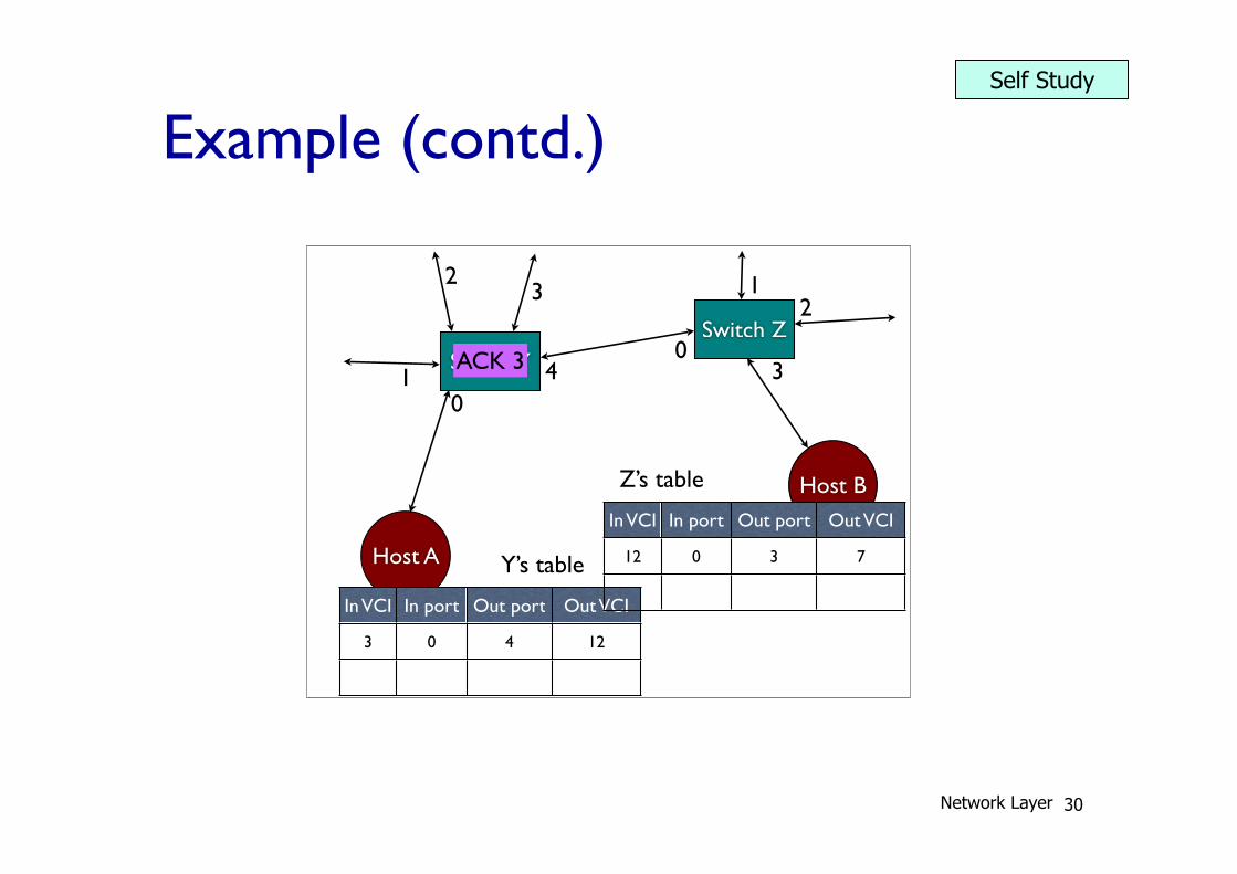
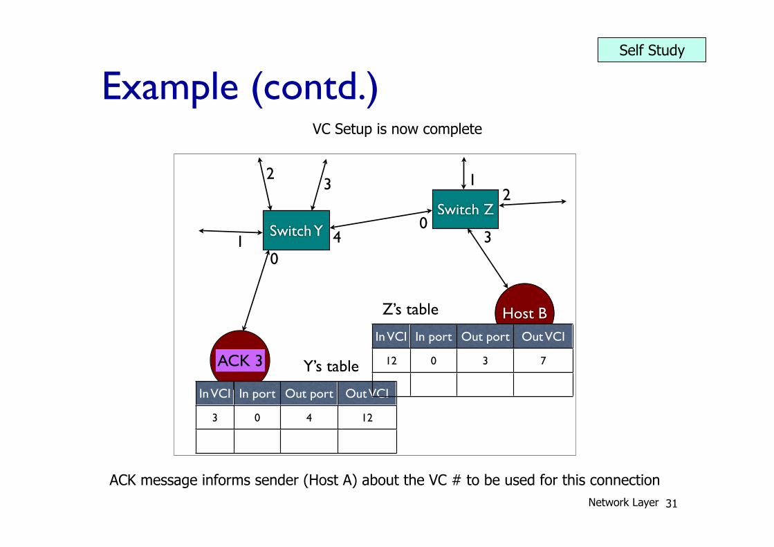
ACK message informs sender (Host A) about the VC # to be used for this connection
VC Setup is now complete
Network Layer
Self Study
Example (contd.)
32
01
23
40
12
3
3 0 4
Y’s table 12 0 3
Z’s table
ACK 7
01
23
40
12
3
3 0 4
Y’s table 12 0 3 7
Z’s table
ACK 12
01
23
40
12
3
3 0 4
Y’s table 12 0 3 7
Z’s table
ACK 12
01
23
40
12
3
3 0 4 12
Y’s table 12 0 3 7
Z’s table
ACK 3
01
23
40
12
3
3 0 4 12
Y’s table 12 0 3 7
Z’s table
ACK 3 Host A
Host B
Switch Y
Switch Z
01
23
40
12
3
In VCI In port Out port Out VCI
3 0 4 12
Y’s table
In VCI In port Out port Out VCI
12 0 3 7
Z’s table
I love you! 3
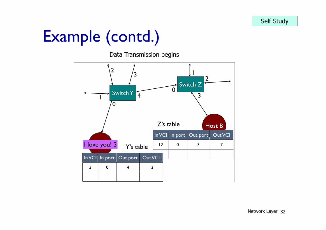
Data Transmission begins
Network Layer
Self Study
Example (contd.)
33
Host A
Host B
Switch Y
Switch Z
01
23
40
12
3
In VCI In port Out port Out VCI
3 0 4 12
Y’s table
In VCI In port Out port Out VCI
12 0 3 7
Z’s table
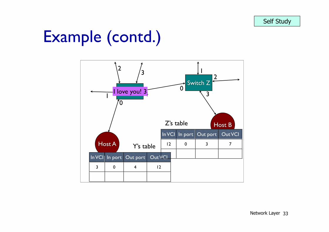
I love you! 3
01
23
40
12
3
3 0 4 12
Y’s table 12 0 3 7
Z’s table
I love you! 12
01
23
40
12
3
3 0 4 12
Y’s table 12 0 3 7
Z’s table
I love you! 12
01
23
40
12
3
3 0 4 12
Y’s table 12 0 3 7
Z’s table
I love you! 7
01
23
40
12
3
3 0 4 12
Y’s table 12 0 3 7
Z’s table I love you! 7
Addressing properties
• Addresses are only used for connection set-up (“signalling”)
• Virtual Circuit Identifiers (VCIs) are used for sending messages and for “teardown”
• This doesn’t scale! Every connection needs an entry in every switch along the way!
• Or does it?
Network Layer
Self Study

Example (contd.)
34
01
23
40
12
3
3 0 4 12
Y’s table 12 0 3 7
Z’s table
I love you! 3
Host A
Host B
Switch Y
Switch Z
01
23
40
12
3
In VCI In port Out port Out VCI
3 0 4 12
Y’s table
In VCI In port Out port Out VCI
12 0 3 7
Z’s table
I love you! 12
01
23
40
12
3
3 0 4 12
Y’s table 12 0 3 7
Z’s table
I love you! 12
01
23
40
12
3
3 0 4 12
Y’s table 12 0 3 7
Z’s table
I love you! 7
01
23
40
12
3
3 0 4 12
Y’s table 12 0 3 7
Z’s table I love you! 7
Addressing properties
• Addresses are only used for connection set-up (“signalling”)
• Virtual Circuit Identifiers (VCIs) are used for sending messages and for “teardown”
• This doesn’t scale! Every connection needs an entry in every switch along the way!
• Or does it?
Network Layer
Self Study

Example (contd.)
35
01
23
40
12
3
3 0 4 12
Y’s table 12 0 3 7
Z’s table
I love you! 3
01
23
40
12
3
3 0 4 12
Y’s table 12 0 3 7
Z’s table
I love you! 12
Host A
Host B
Switch Y
Switch Z
01
23
40
12
3
In VCI In port Out port Out VCI
3 0 4 12
Y’s table
In VCI In port Out port Out VCI
12 0 3 7
Z’s table
I love you! 12
01
23
40
12
3
3 0 4 12
Y’s table 12 0 3 7
Z’s table
I love you! 7
01
23
40
12
3
3 0 4 12
Y’s table 12 0 3 7
Z’s table I love you! 7
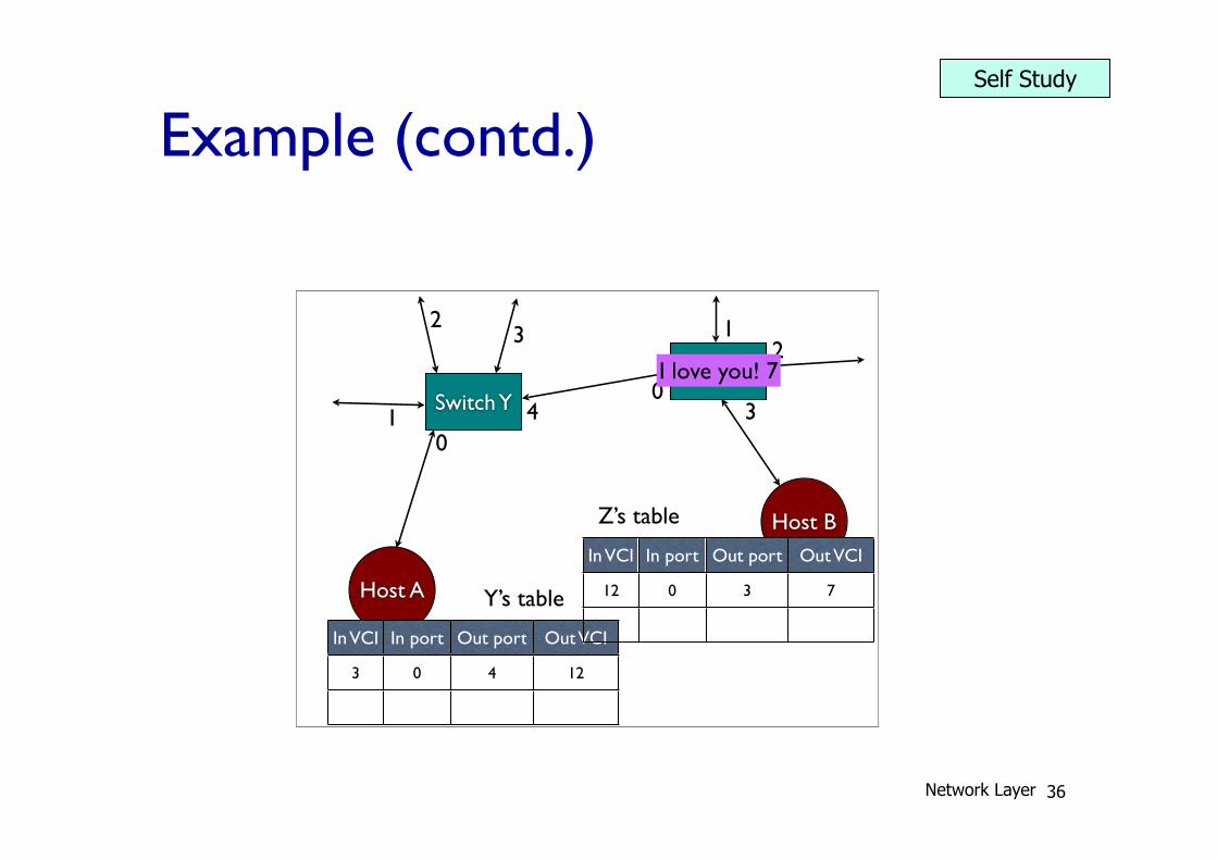
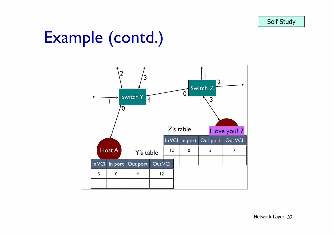
Addressing properties
• Addresses are only used for connection set-up (“signalling”)
• Virtual Circuit Identifiers (VCIs) are used for sending messages and for “teardown”
• This doesn’t scale! Every connection needs an entry in every switch along the way!
• Or does it?
Network Layer
Self Study
Example (contd.)
36
01
23
40
12
3
3 0 4 12
Y’s table 12 0 3 7
Z’s table
I love you! 3
01
23
40
12
3
3 0 4 12
Y’s table 12 0 3 7
Z’s table
I love you! 12
01
23
40
12
3
3 0 4 12
Y’s table 12 0 3 7
Z’s table
I love you! 12
Host A
Host B
Switch Y
Switch Z
01
23
40
12
3
In VCI In port Out port Out VCI
3 0 4 12
Y’s table
In VCI In port Out port Out VCI
12 0 3 7
Z’s table
I love you! 7
01
23
40
12
3
3 0 4 12
Y’s table 12 0 3 7
Z’s table I love you! 7
Addressing properties
• Addresses are only used for connection set-up (“signalling”)
• Virtual Circuit Identifiers (VCIs) are used for sending messages and for “teardown”
• This doesn’t scale! Every connection needs an entry in every switch along the way!
• Or does it?
Network Layer
Self Study
Example (contd.)
37
01
23
40
12
3
3 0 4 12
Y’s table 12 0 3 7
Z’s table
I love you! 3
01
23
40
12
3
3 0 4 12
Y’s table 12 0 3 7
Z’s table
I love you! 12
01
23
40
12
3
3 0 4 12
Y’s table 12 0 3 7
Z’s table
I love you! 12
01
23
40
12
3
3 0 4 12
Y’s table 12 0 3 7
Z’s table
I love you! 7
Host A
Host B
Switch Y
Switch Z
01
23
40
12
3
In VCI In port Out port Out VCI
3 0 4 12
Y’s table
In VCI In port Out port Out VCI
12 0 3 7
Z’s table I love you! 7
Addressing properties
• Addresses are only used for connection set-up (“signalling”)
• Virtual Circuit Identifiers (VCIs) are used for sending messages and for “teardown”
• This doesn’t scale! Every connection needs an entry in every switch along the way!
• Or does it?
Network Layer
Self Study
38
application transport network data link physical
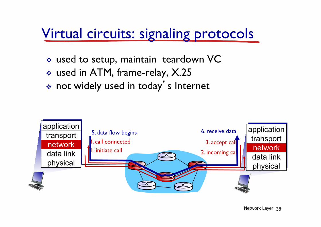
Virtual circuits: signaling protocols v used to setup, maintain teardown VC v used in ATM, frame-relay, X.25 v not widely used in today’s Internet
1. initiate call 2. incoming call 3. accept call 4. call connected
5. data flow begins 6. receive data application transport network data link physical
Network Layer
39
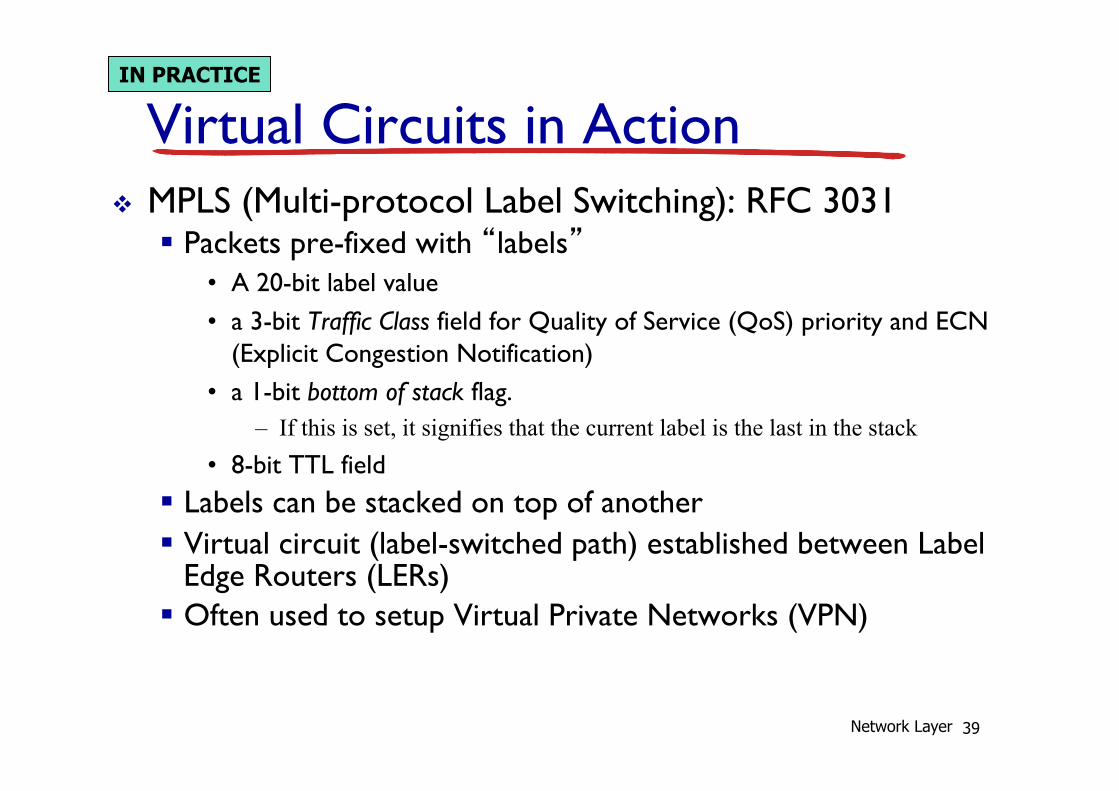
Virtual Circuits in Action v MPLS (Multi-protocol Label Switching): RFC 3031
§ Packets pre-fixed with “labels” • A 20-bit label value • a 3-bit Traffic Class field for Quality of Service (QoS) priority and ECN
(Explicit Congestion Notification) • a 1-bit bottom of stack flag.
– If this is set, it signifies that the current label is the last in the stack • 8-bit TTL field
§ Labels can be stacked on top of another § Virtual circuit (label-switched path) established between Label
Edge Routers (LERs) § Often used to setup Virtual Private Networks (VPN)
IN PRACTICE
Network Layer
40
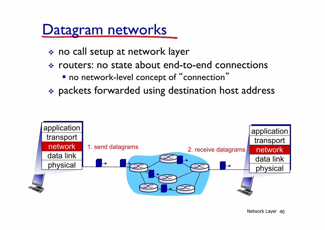
Datagram networks v no call setup at network layer v routers: no state about end-to-end connections
§ no network-level concept of “connection” v packets forwarded using destination host address
1. send datagrams application transport network data link physical
application transport network data link physical
2. receive datagrams
Network Layer
41
1
2 3
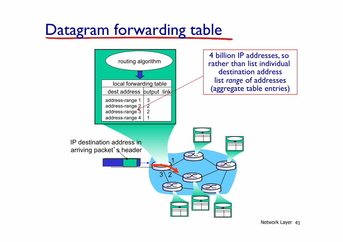
Datagram forwarding table
IP destination address in arriving packet’s header
routing algorithm
local forwarding table dest address output link
address-range 1 address-range 2 address-range 3 address-range 4
3 2 2 1
4 billion IP addresses, so rather than list individual
destination address list range of addresses
(aggregate table entries)
Network Layer
42
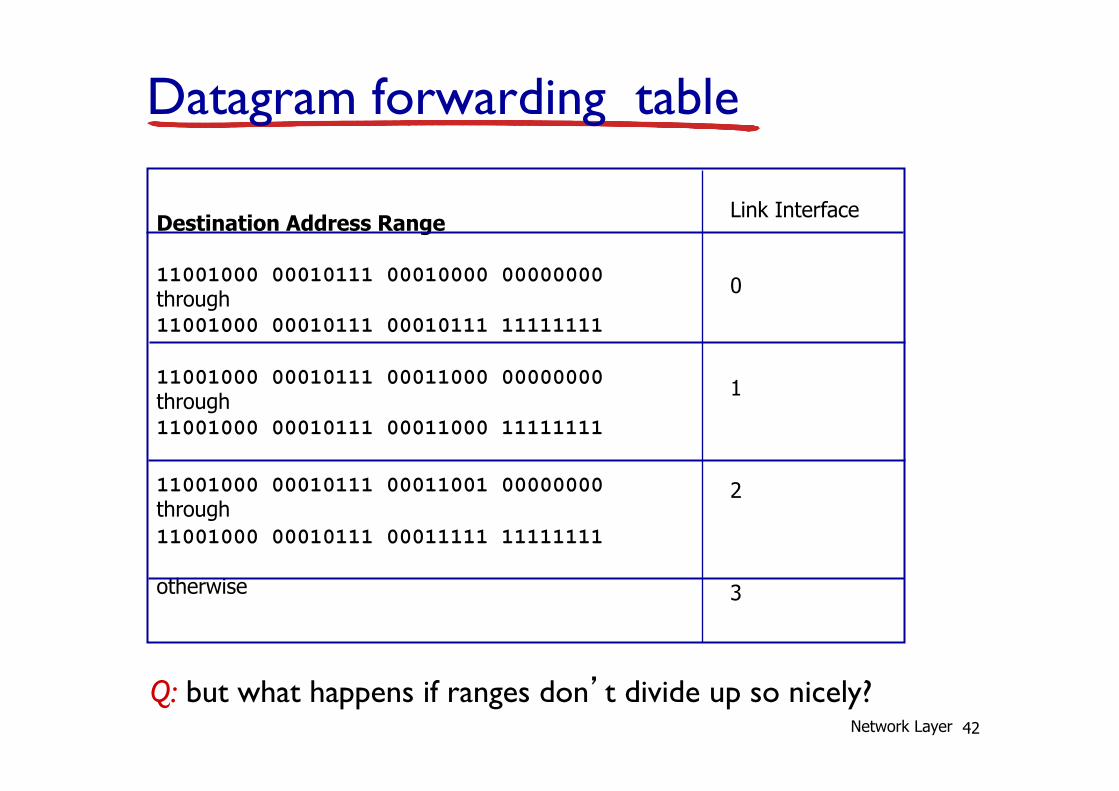
Destination Address Range 11001000 00010111 00010000 00000000 through 11001000 00010111 00010111 11111111 11001000 00010111 00011000 00000000 through 11001000 00010111 00011000 11111111 11001000 00010111 00011001 00000000 through 11001000 00010111 00011111 11111111 otherwise
Link Interface 0 1 2 3
Q: but what happens if ranges don’t divide up so nicely?
Datagram forwarding table
Network Layer
43
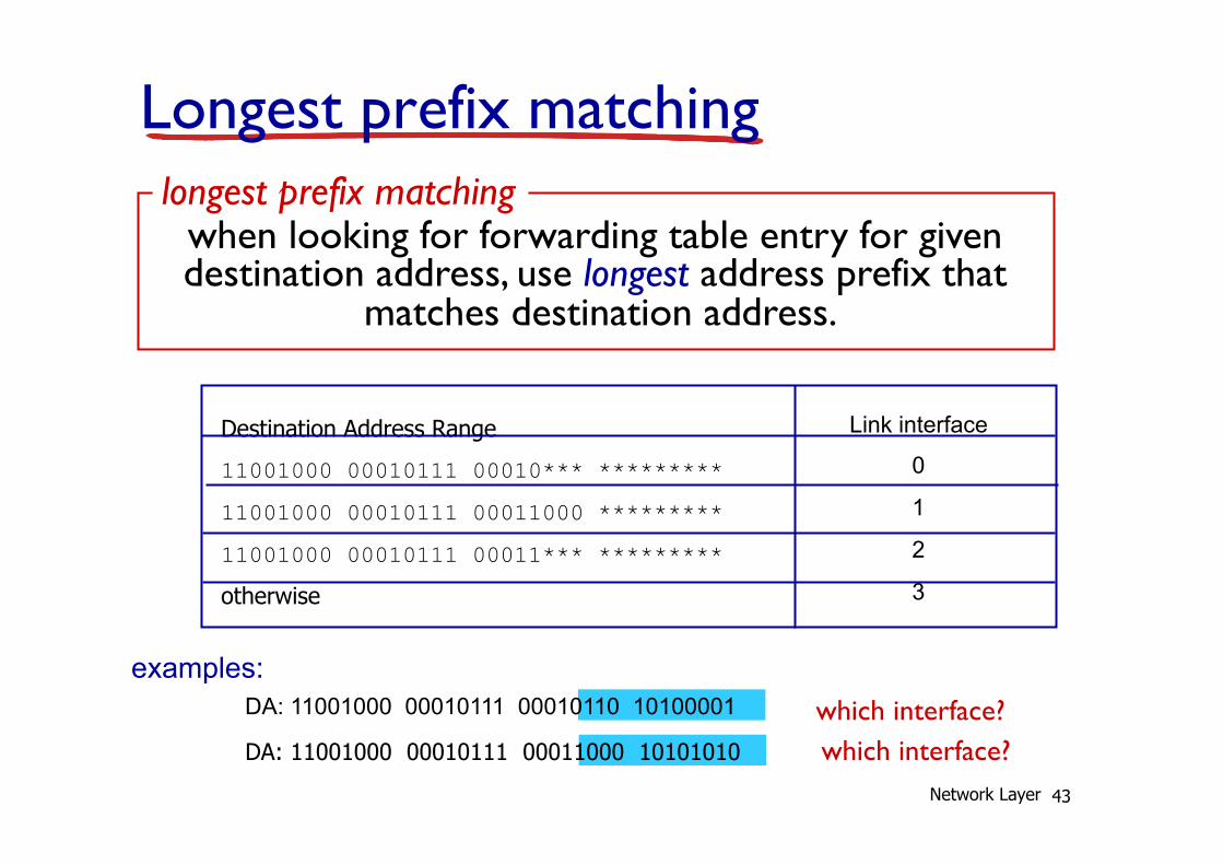
Longest prefix matching
Destination Address Range
11001000 00010111 00010*** *********
11001000 00010111 00011000 *********
11001000 00010111 00011*** ********* otherwise
DA: 11001000 00010111 00011000 10101010
examples: DA: 11001000 00010111 00010110 10100001 which interface?
which interface?
when looking for forwarding table entry for given destination address, use longest address prefix that
matches destination address.
longest prefix matching
Link interface
0
1
2
3
Network Layer

44
Datagram or VC network: why? Internet (datagram) v data exchange among
computers § “elastic” service, no strict
timing req. v many link types
§ different characteristics § uniform service difficult
v “smart” end systems (computers) § can adapt, perform control,
error recovery § simple inside network,
complexity at “edge”
ATM (VC) v evolved from telephony v human conversation:
§ strict timing, reliability requirements
§ need for guaranteed service v “dumb” end systems
§ telephones § complexity inside network
Network Layer
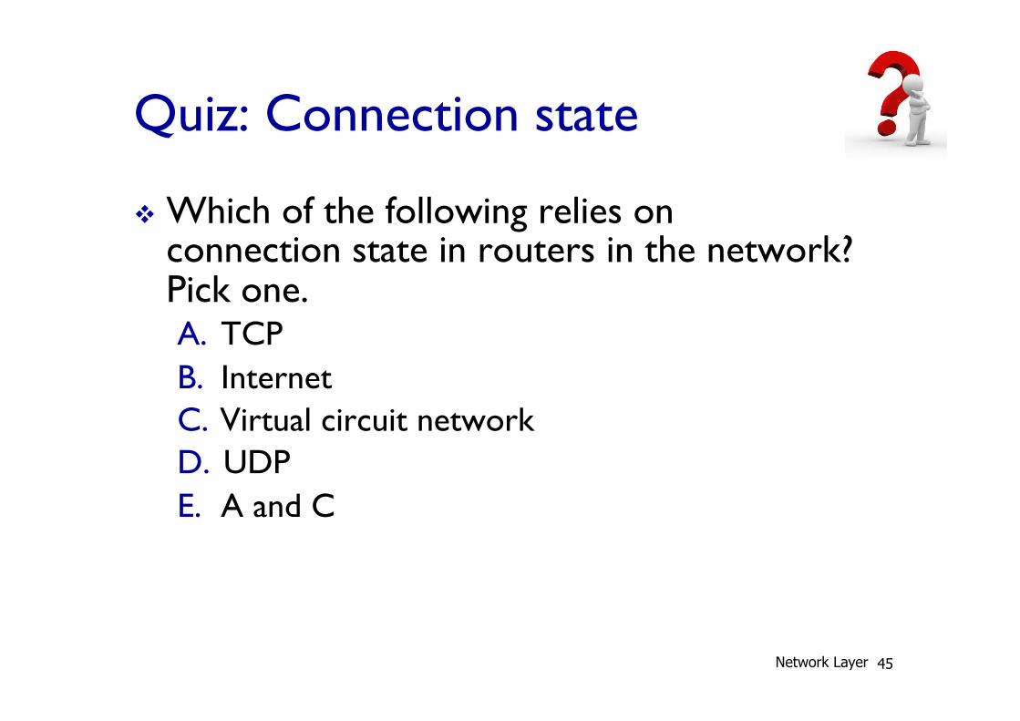
Quiz: Connection state
v Which of the following relies on connection state in routers in the network? Pick one. A. TCP B. Internet C. Virtual circuit network D. UDP E. A and C
45 Network Layer

Quiz: Virtual circuit
v Which of the following is true? Pick one.
A. A virtual circuit uses a different VC number for each link along a route
B. A virtual circuit uses the same VC number for all packets in a connection
C. A virtual circuit router uses the destination address (among other fields) in order to determine the outgoing interface
D. A and C
46 Network Layer
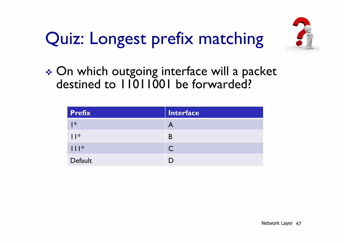
Quiz: Longest prefix matching
v On which outgoing interface will a packet destined to 11011001 be forwarded?
47
Prefix Interface
1* A
11* B
111* C
Default D
Network Layer
48
4.1 introduction 4.2 virtual circuit and
datagram networks 4.3 what’s inside a router 4.4 IP: Internet Protocol
§ datagram format § IPv4 addressing § ICMP § IPv6
4.5 routing algorithms § link state § distance vector § hierarchical routing
4.6 routing in the Internet § RIP § OSPF § BGP
4.7 broadcast and multicast routing
Network Layer: outline
Network Layer
IP Routers
v Core building block of the Internet infrastructure
v $120B+ industry
v Vendors: Cisco, Huawei, Juniper, Alcatel-Lucent (account for >90%)
Network Layer 49
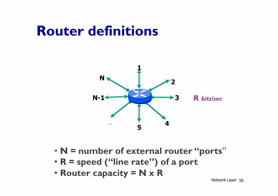
Router definitions
1
2
3
4 5 …
N-1
N
• N = number of external router “ports” • R = speed (“line rate”) of a port • Router capacity = N x R
R bits/sec
Network Layer 50
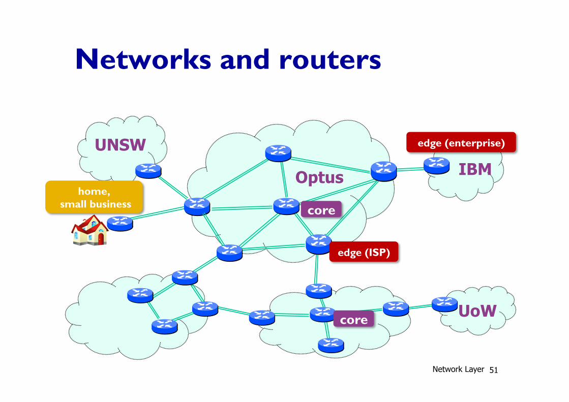
Networks and routers
Optus IBM
UoW
UNSW
core
core
edge (ISP)
edge (enterprise)
home, small business
Network Layer 51
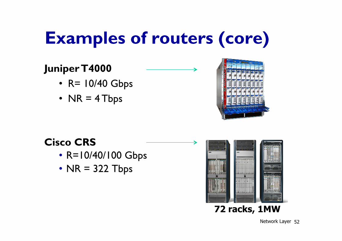
Examples of routers (core)
72 racks, 1MW
Cisco CRS • R=10/40/100 Gbps • NR = 322 Tbps
Juniper T4000 • R= 10/40 Gbps • NR = 4 Tbps
Network Layer 52
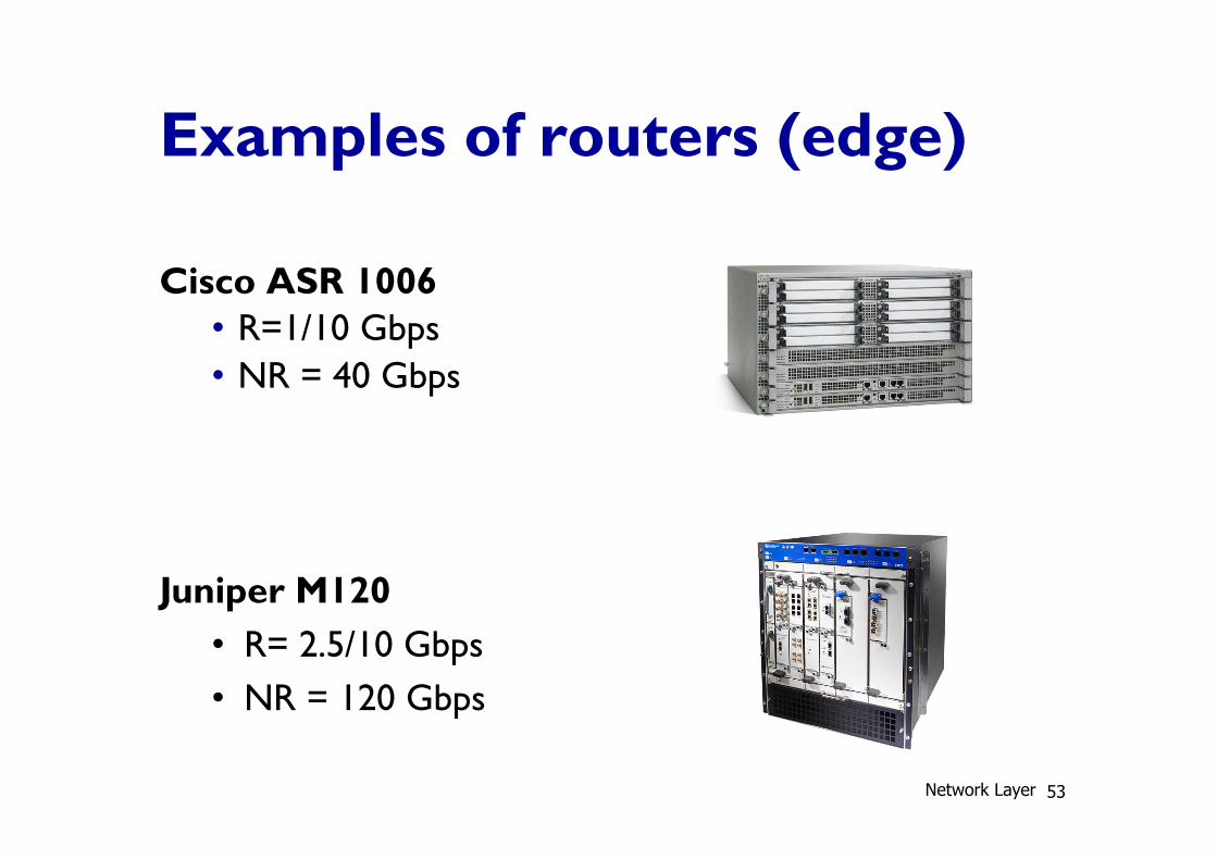
Examples of routers (edge)
Cisco ASR 1006 • R=1/10 Gbps • NR = 40 Gbps
Juniper M120 • R= 2.5/10 Gbps • NR = 120 Gbps
Network Layer 53
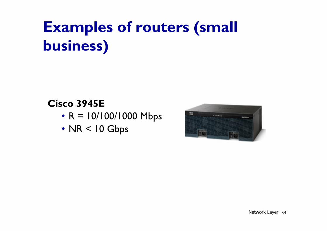
Examples of routers (small business)
Cisco 3945E • R = 10/100/1000 Mbps • NR < 10 Gbps
Network Layer 54
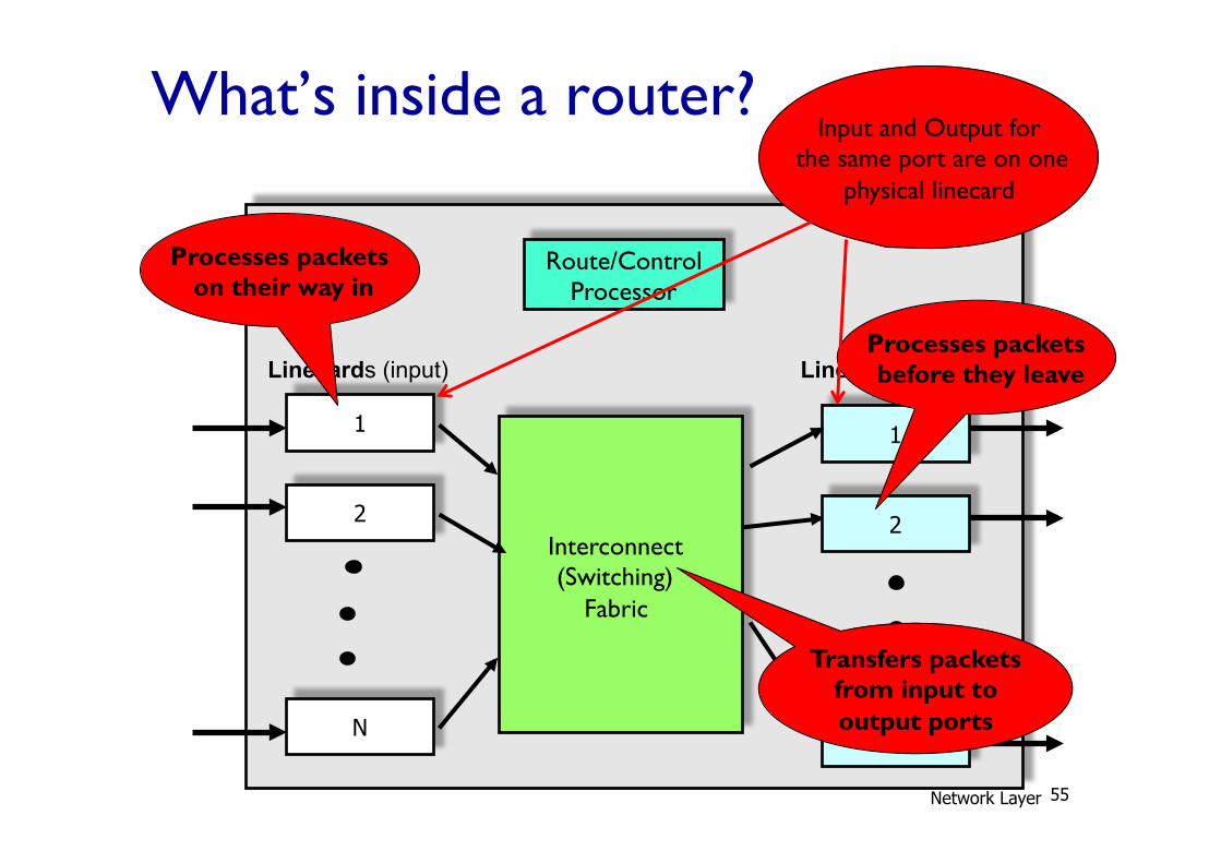
What’s inside a router?
1
2
N
1
2
N
Linecards (input)
Interconnect (Switching)
Fabric
Route/Control Processor
Linecards (output)
Processes packets on their way in
Processes packets before they leave
Transfers packets from input to output ports
Input and Output for the same port are on one
physical linecard
Network Layer 55
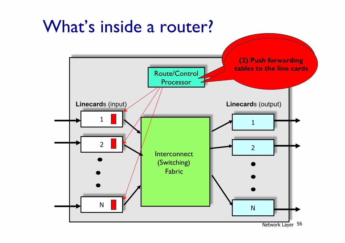
What’s inside a router?
1
2
N
1
2
N
Linecards (input)
Interconnect (Switching)
Fabric
Route/Control Processor
Linecards (output)
(1) Implement IGP and BGP protocols;
compute routing tables (2) Push forwarding
tables to the line cards
Network Layer 56
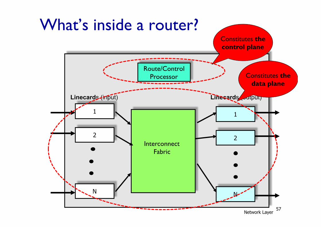
What’s inside a router?
1
2
N
1
2
N
Linecards (input)
Interconnect Fabric
Route/Control Processor
Linecards (output)
Constitutes the data plane
Constitutes the control plane
Network Layer 57
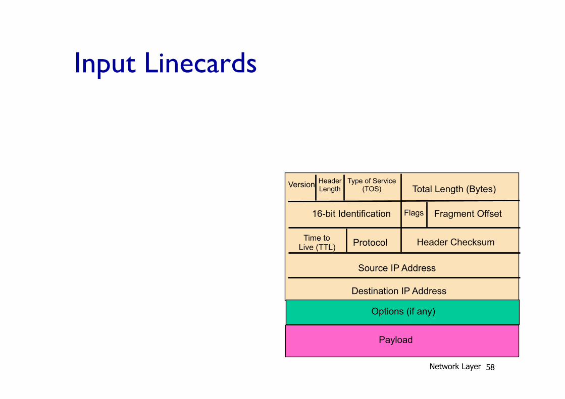
Input Linecards
Version Header Length
Type of Service (TOS) Total Length (Bytes)
16-bit Identification Flags Fragment Offset
Time to Live (TTL) Protocol Header Checksum
Source IP Address
Destination IP Address
Options (if any)
Payload
Network Layer 58
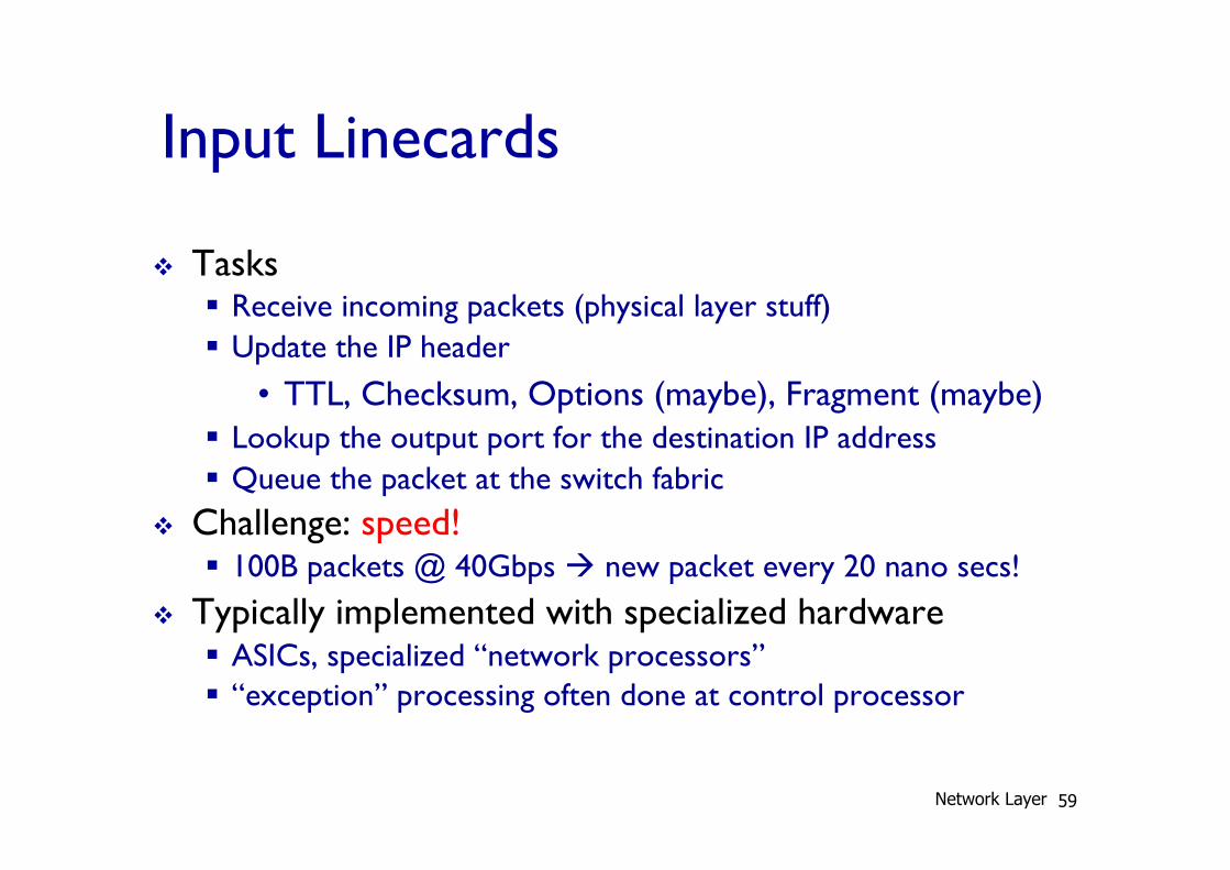
Input Linecards
v Tasks § Receive incoming packets (physical layer stuff) § Update the IP header
• TTL, Checksum, Options (maybe), Fragment (maybe) § Lookup the output port for the destination IP address § Queue the packet at the switch fabric
v Challenge: speed! § 100B packets @ 40Gbps à new packet every 20 nano secs!
v Typically implemented with specialized hardware § ASICs, specialized “network processors” § “exception” processing often done at control processor
Network Layer 59
IP Lookup
v IP addressing and routing (to be discussed) § For scalability, multiple IP addresses are aggregated § Routing protocols operates on IP address prefixes
( “a.b.c.d/n” notation) § IP routing tables maintain a mapping from IP prefixes
to output interfaces
v Route lookup à find the longest prefix in the table that matches the packet destination address § Longest Prefix Match (LPM) lookup
Network Layer 60
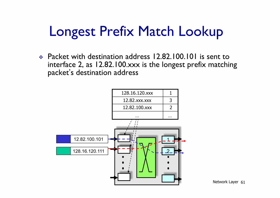
Longest Prefix Match Lookup
v Packet with destination address 12.82.100.101 is sent to interface 2, as 12.82.100.xxx is the longest prefix matching packet’s destination address
1
2 128.16.120.111
12.82.100.101
… …
3 12.82.xxx.xxx
1 128.16.120.xxx
12.82.100.xxx 2
Network Layer 61
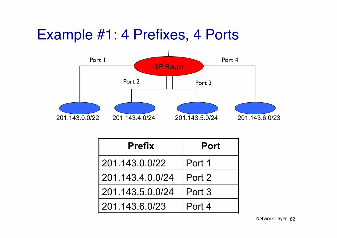
Example #1: 4 Prefixes, 4 Ports
Prefix Port
201.143.0.0/22 Port 1 201.143.4.0.0/24 Port 2 201.143.5.0.0/24 Port 3 201.143.6.0/23 Port 4
201.143.0.0/22 201.143.4.0/24 201.143.5.0/24 201.143.6.0/23
ISP Router Port 1
Port 2 Port 3
Port 4
Network Layer 62
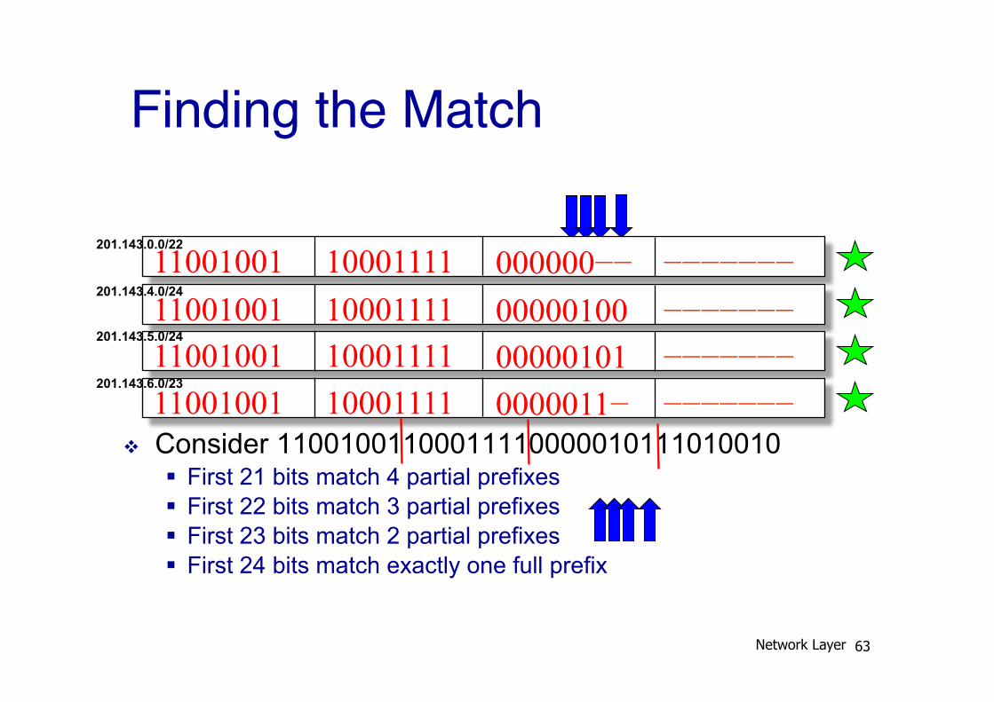
Finding the Match
v Consider 11001001100011110000010111010010 § First 21 bits match 4 partial prefixes § First 22 bits match 3 partial prefixes § First 23 bits match 2 partial prefixes § First 24 bits match exactly one full prefix
11001001 10001111 000000−− −−−−−−− 11001001 10001111 00000100 −−−−−−− 11001001 10001111 00000101 −−−−−−− 11001001 10001111 0000011− −−−−−−−
201.143.0.0/22
201.143.4.0/24
201.143.5.0/24
201.143.6.0/23
Network Layer 63
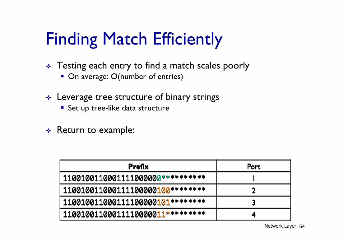
Finding Match Efficiently v Testing each entry to find a match scales poorly
§ On average: O(number of entries)
v Leverage tree structure of binary strings § Set up tree-like data structure
v Return to example:
Prefix Port
1100100110001111000000********** 1
110010011000111100000100******** 2
110010011000111100000101******** 3
11001001100011110000011********* 4
Prefix Port
1100100110001111000000********** 1
110010011000111100000100******** 2
110010011000111100000101******** 3
11001001100011110000011********* 4 Network Layer 64
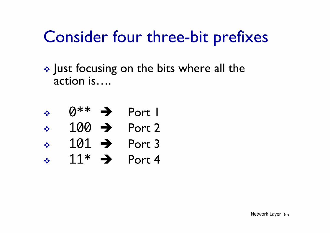
Consider four three-bit prefixes
v Just focusing on the bits where all the action is….
v 0** è Port 1 v 100 è Port 2 v 101 è Port 3 v 11* è Port 4
Network Layer 65

Tree Structure
00*
000 001
0 1 01*
010 011
0 1 11*
110 111
0 1 10*
100 101
0 1
0** 0 1
1** 0 1
***
0 1
0** è Port 1 100 è Port 2 101 è Port 3 11* è Port 4
Network Layer 66
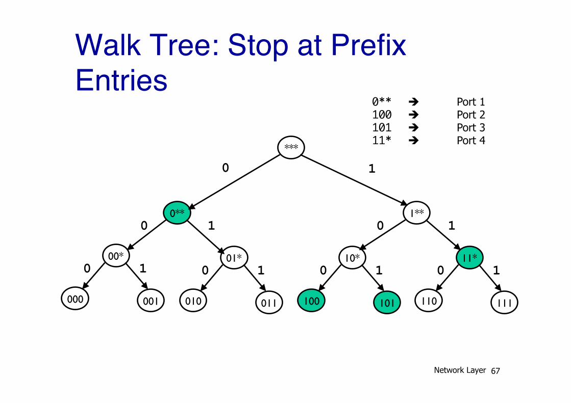
Walk Tree: Stop at Prefix Entries
00*
000 001
0 1 01*
010 011
0 1 11*
110 111
0 1 10*
100 101
0 1
0** 0 1
1** 0 1
***
0 1
0** è Port 1 100 è Port 2 101 è Port 3 11* è Port 4
Network Layer 67
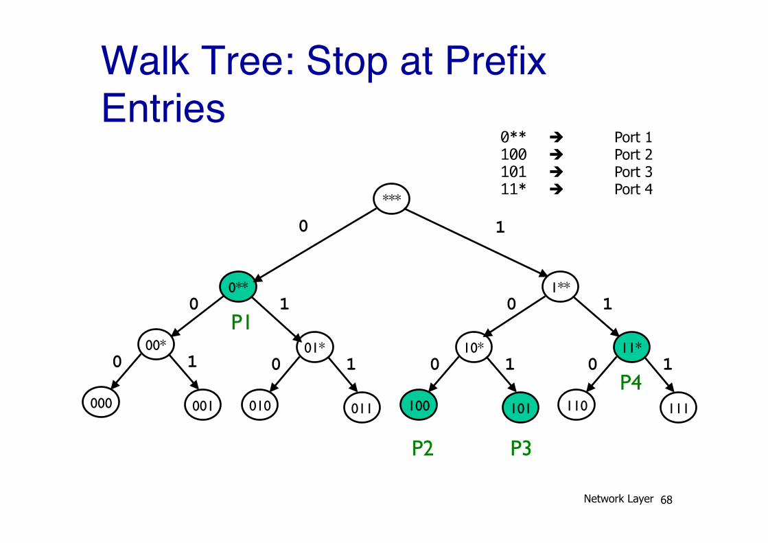
Walk Tree: Stop at Prefix Entries
00*
000 001
0 1 01*
010 011
0 1 11*
110 111
0 1 10*
100 101
0 1
0** 0 1
1** 0 1
***
0 1
P1
P2 P3
P4
0** è Port 1 100 è Port 2 101 è Port 3 11* è Port 4
Network Layer 68
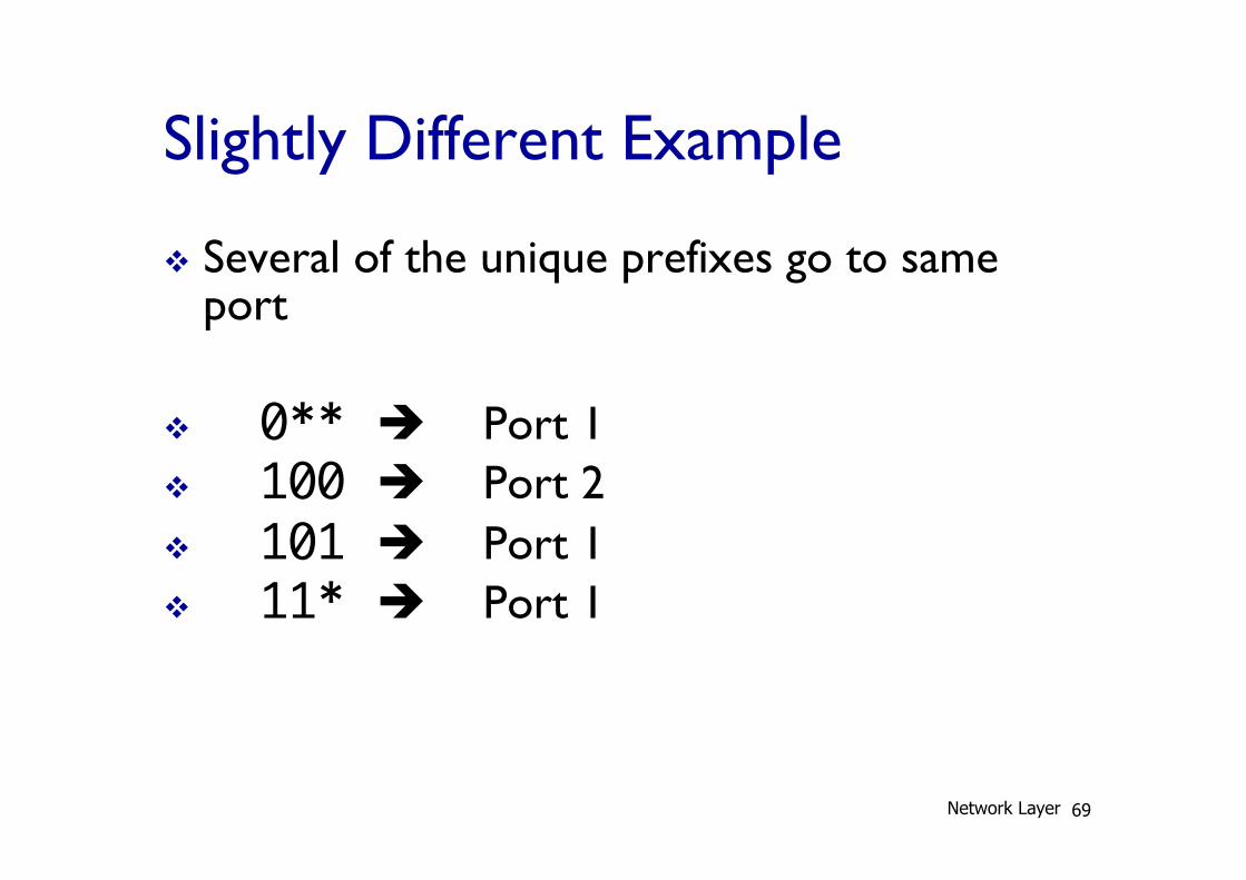
Slightly Different Example
v Several of the unique prefixes go to same port
v 0** è Port 1 v 100 è Port 2 v 101 è Port 1 v 11* è Port 1
Network Layer 69
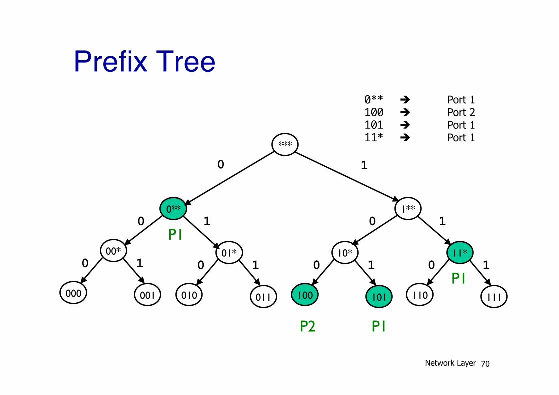
Prefix Tree
00*
000 001
0 1 01*
010 011
0 1 11*
110 111
0 1 10*
100 101
0 1
0** 0 1
1** 0 1
***
0 1
P1
P2 P1
P1
0** è Port 1 100 è Port 2 101 è Port 1 11* è Port 1
Network Layer 70
LPM in real routers
v Real routers use far more advanced/complex solutions than the approaches I just described § but what we discussed is their starting point
v With many heuristics and optimizations that leverage real-world patterns § Some destinations more popular than others § Some ports lead to more destinations § Typical prefix granularities
Network Layer 71
Recap: Input linecards
v Main challenge is processing speeds v Tasks involved:
§ Update packet header (easy) § LPM lookup on destination address (harder)
v Mostly implemented with specialized hardware
Network Layer 72
Output Linecard
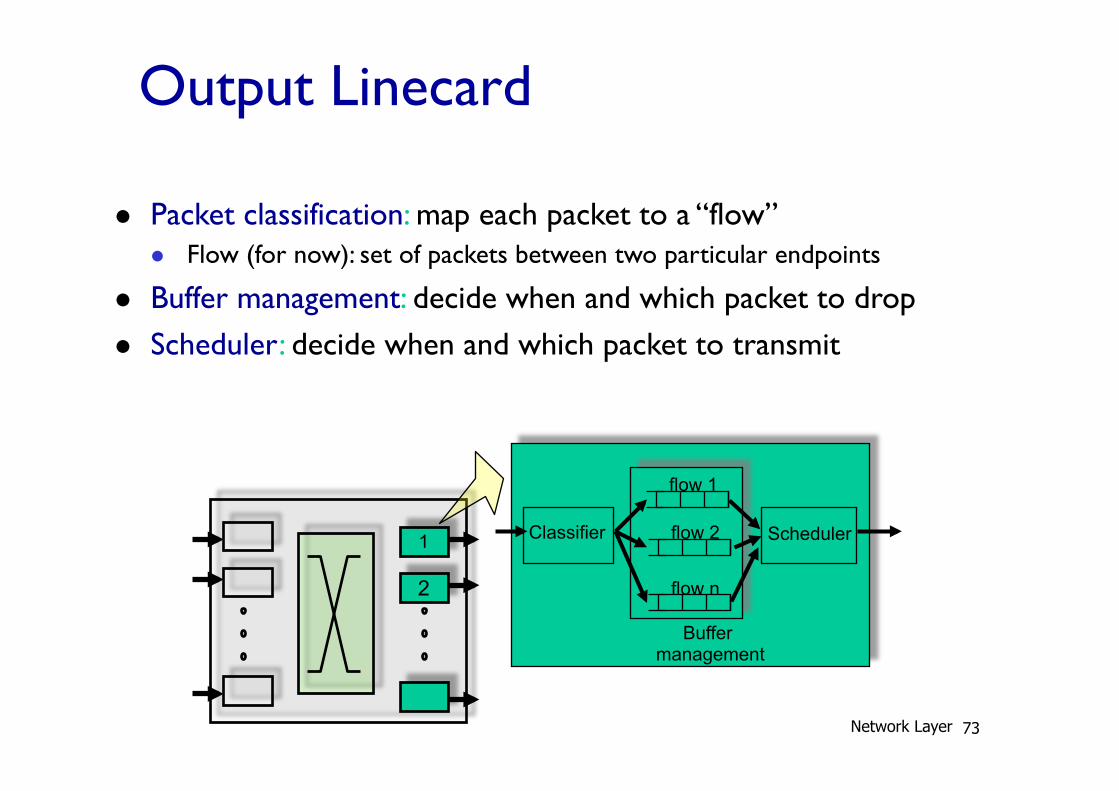
l Packet classification: map each packet to a “flow” l Flow (for now): set of packets between two particular endpoints
l Buffer management: decide when and which packet to drop l Scheduler: decide when and which packet to transmit
1
2
Scheduler
flow 1
flow 2
flow n
Classifier
Buffer management
Network Layer 73
Output Linecard
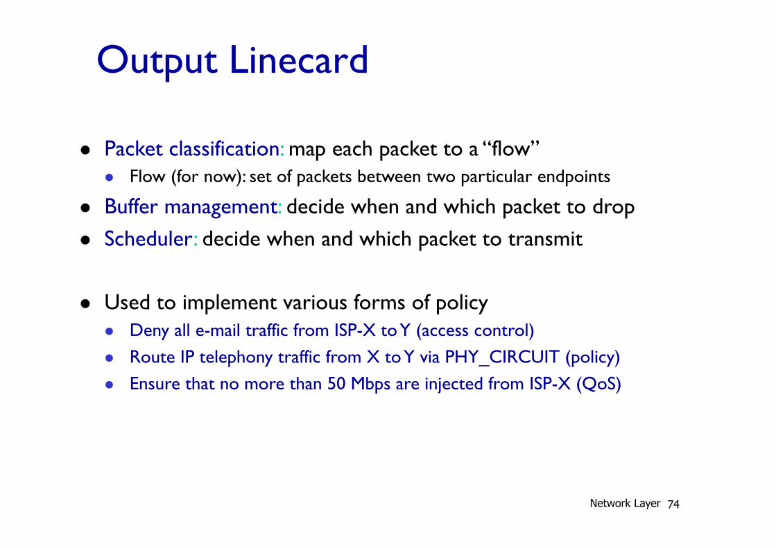
l Packet classification: map each packet to a “flow” l Flow (for now): set of packets between two particular endpoints
l Buffer management: decide when and which packet to drop l Scheduler: decide when and which packet to transmit
l Used to implement various forms of policy l Deny all e-mail traffic from ISP-X to Y (access control) l Route IP telephony traffic from X to Y via PHY_CIRCUIT (policy) l Ensure that no more than 50 Mbps are injected from ISP-X (QoS)
Network Layer 74
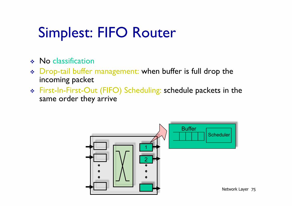
Simplest: FIFO Router
v No classification v Drop-tail buffer management: when buffer is full drop the
incoming packet v First-In-First-Out (FIFO) Scheduling: schedule packets in the
same order they arrive
1
2
Scheduler Buffer
Network Layer 75
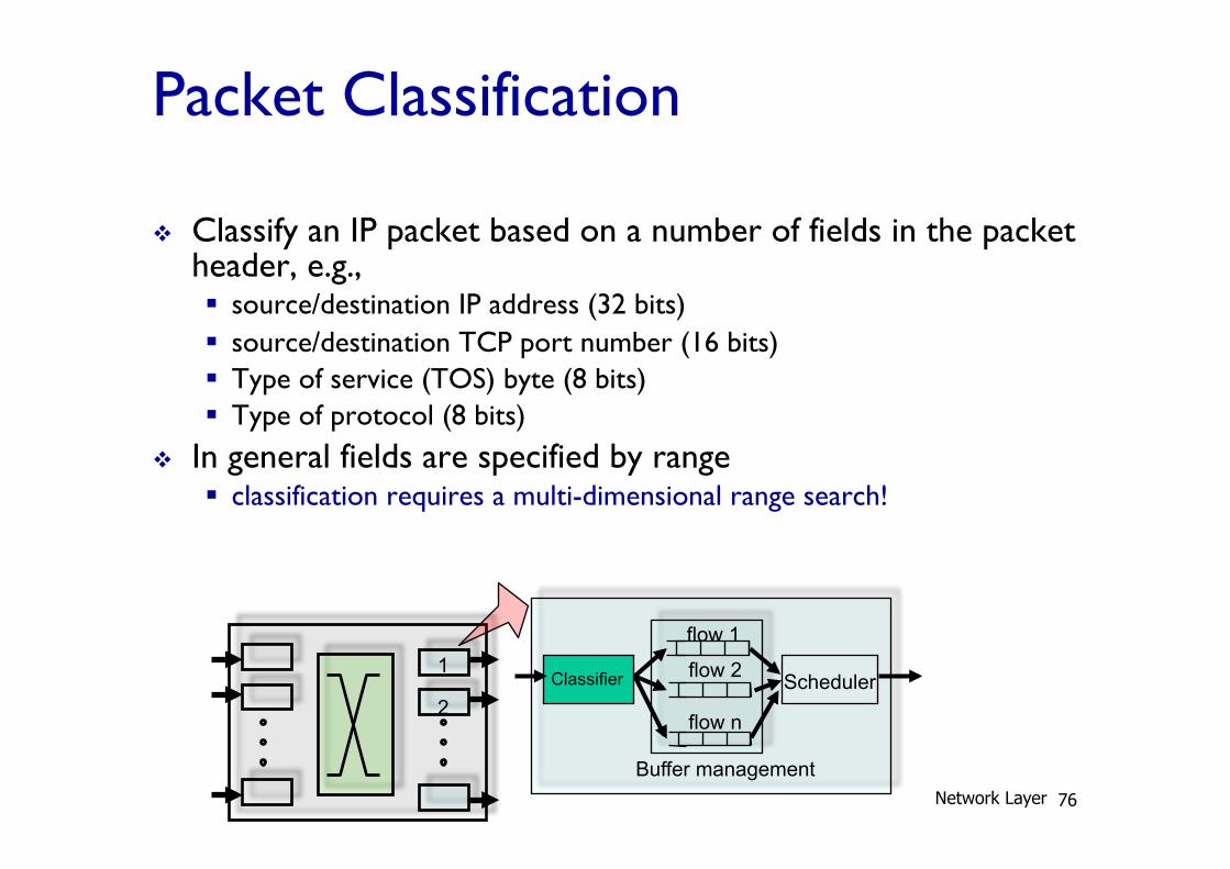
Packet Classification
v Classify an IP packet based on a number of fields in the packet header, e.g., § source/destination IP address (32 bits) § source/destination TCP port number (16 bits) § Type of service (TOS) byte (8 bits) § Type of protocol (8 bits)
v In general fields are specified by range § classification requires a multi-dimensional range search!
1
2 Scheduler
flow 1
flow 2
flow n
Classifier
Buffer management Network Layer 76
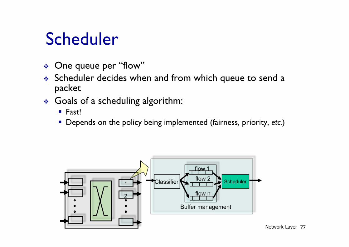
Scheduler v One queue per “flow” v Scheduler decides when and from which queue to send a
packet v Goals of a scheduling algorithm:
§ Fast! § Depends on the policy being implemented (fairness, priority, etc.)
1
2
Scheduler
flow 1
flow 2
flow n
Classifier
Buffer management
Network Layer 77
Priority Scheduler
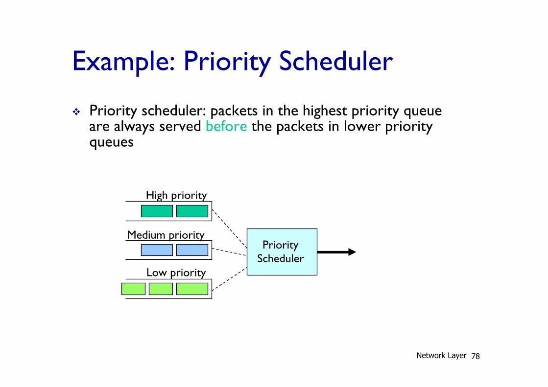
Example: Priority Scheduler
v Priority scheduler: packets in the highest priority queue are always served before the packets in lower priority queues
High priority
Medium priority
Low priority
Network Layer 78
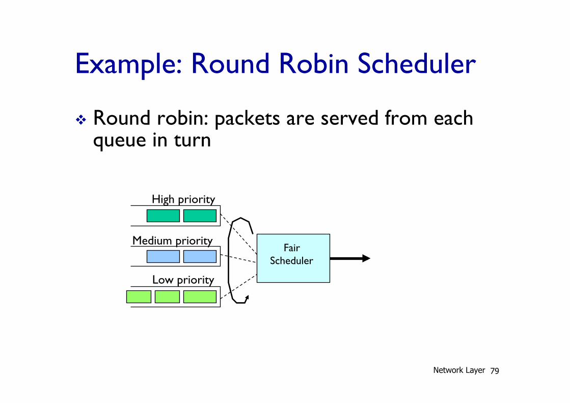
Example: Round Robin Scheduler
v Round robin: packets are served from each queue in turn
Fair Scheduler
High priority
Medium priority
Low priority
Network Layer 79
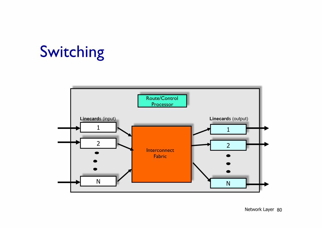
Switching
1
2
N
1
2
N
Linecards (input)
Interconnect Fabric
Route/Control Processor
Linecards (output)
Network Layer 80
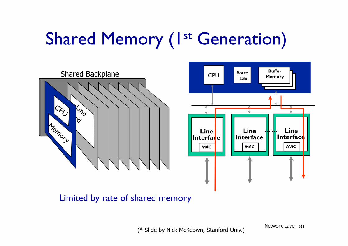
Shared Memory (1st Generation)
Route Table CPU
Buffer Memory
Line Interface
MAC
Line Interface
MAC
Line Interface
MAC
Limited by rate of shared memory
Shared Backplane
(* Slide by Nick McKeown, Stanford Univ.) Network Layer 81
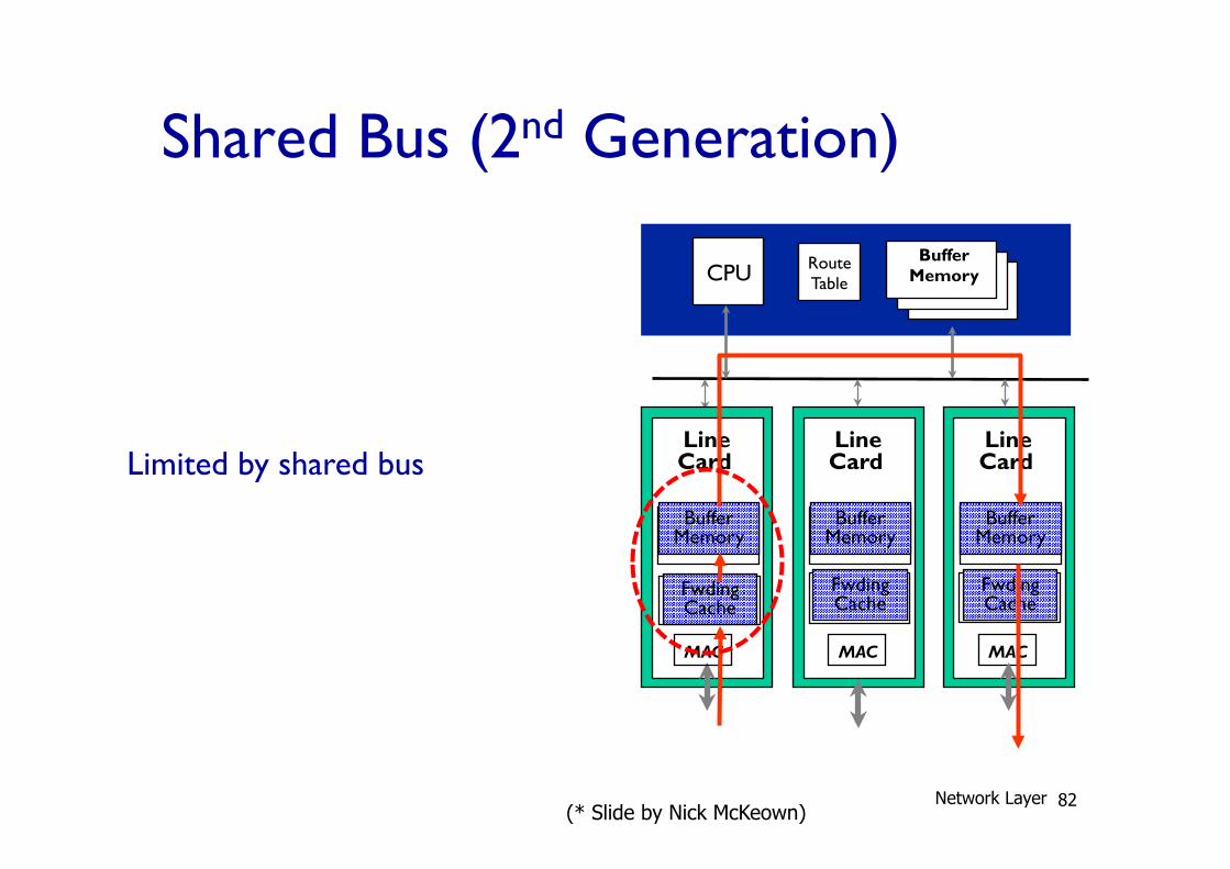
Shared Bus (2nd Generation)
Route Table CPU
Line Card
Buffer Memory
Line Card
MAC
Buffer Memory
Line Card
MAC
Buffer Memory
Fwding Cache
Fwding Cache
Fwding Cache
MAC
Buffer Memory
Limited by shared bus
(* Slide by Nick McKeown) Network Layer 82
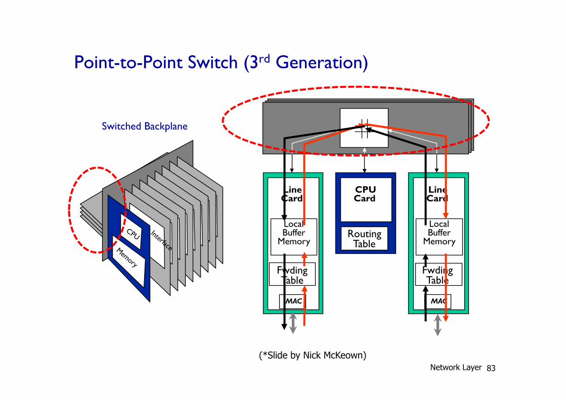
Point-to-Point Switch (3rd Generation)
Line Card
MAC
Local Buffer
Memory
CPU Card
Line Card
MAC
Local Buffer
Memory
Switched Backplane
Fwding Table
Routing Table
Fwding Table
(*Slide by Nick McKeown) Network Layer 83
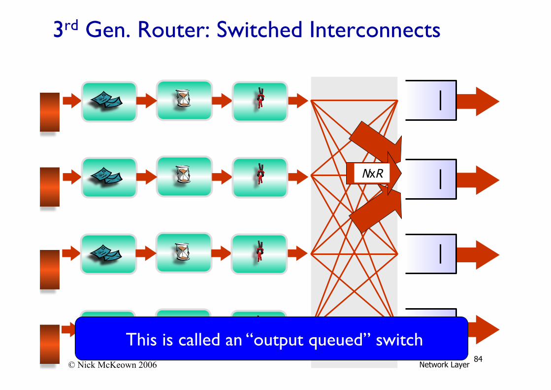
© Nick McKeown 2006
NxR
3rd Gen. Router: Switched Interconnects
This is called an “output queued” switch Network Layer
84
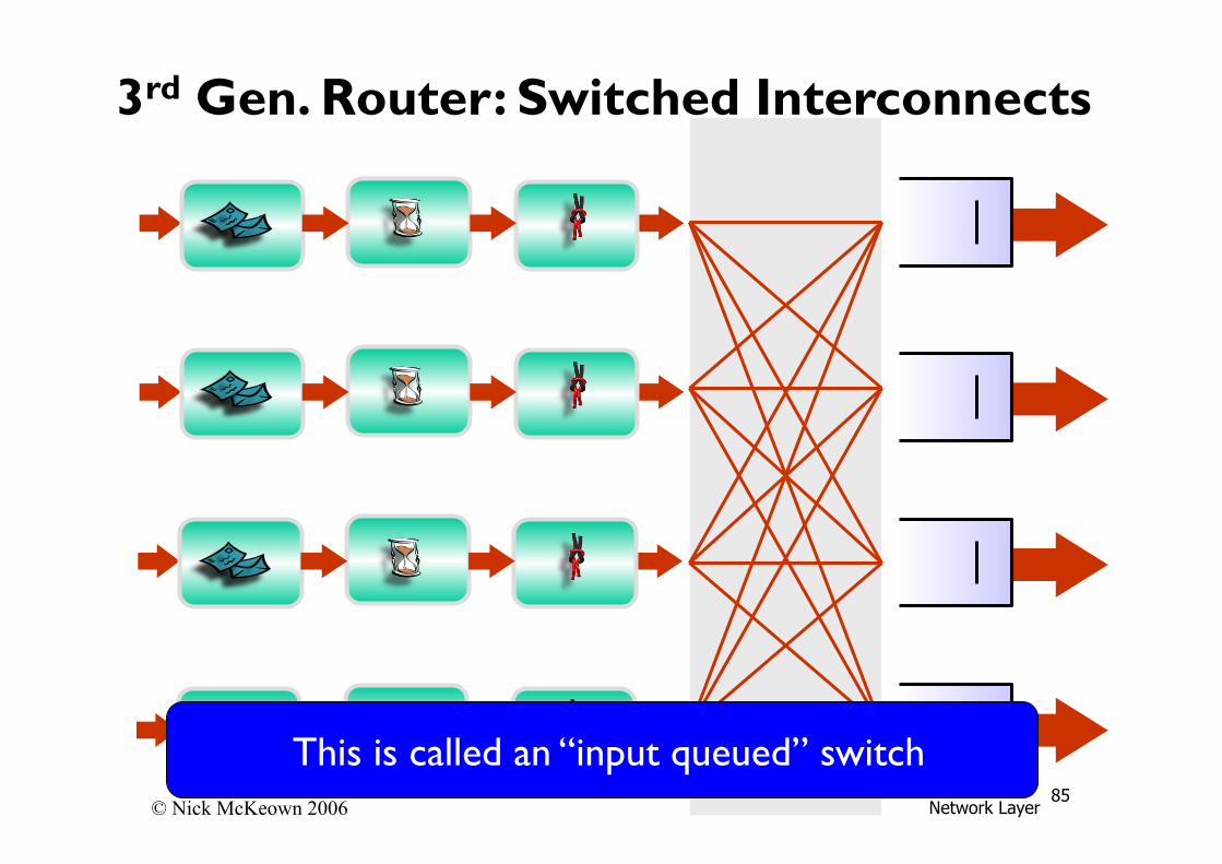
© Nick McKeown 2006
3rd Gen. Router: Switched Interconnects
This is called an “input queued” switch Network Layer
85
Two challenges with input queuing
1) Need an internal fabric scheduler!
Network Layer 86
© Nick McKeown 2006
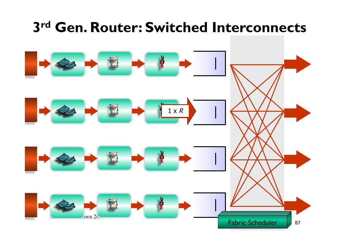
1 x R
Fabric Scheduler
3rd Gen. Router: Switched Interconnects
87
Two challenges with input queuing
1) Need an internal fabric scheduler! 2) Must avoid “head-of-line” blocking
Network Layer 88
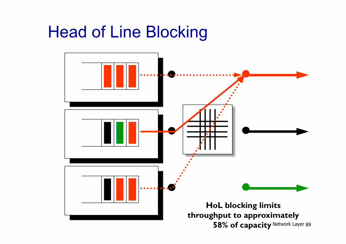
Head of Line Blocking
HoL blocking limits throughput to approximately
58% of capacity Network Layer 89
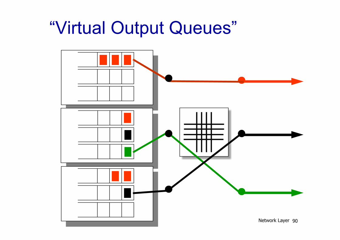
“Virtual Output Queues”
Network Layer 90
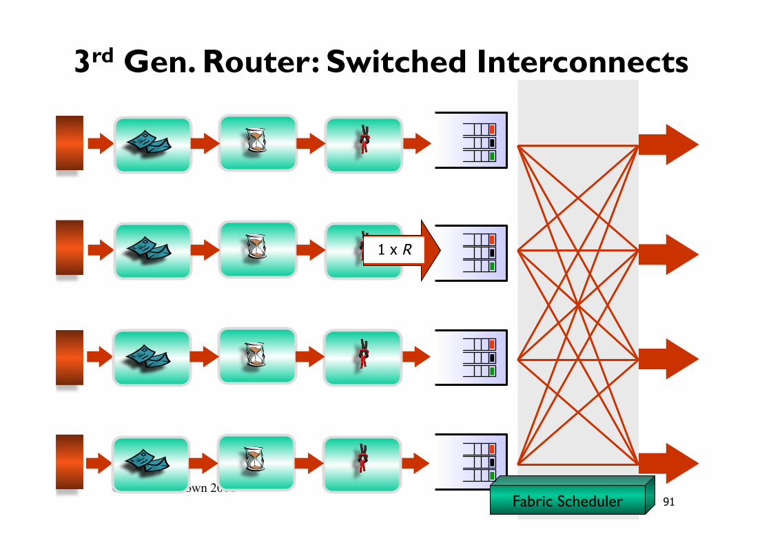
© Nick McKeown 2006
1 x R
Fabric Scheduler
3rd Gen. Router: Switched Interconnects
91
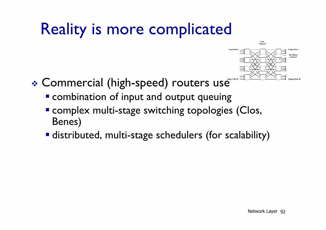
Reality is more complicated
v Commercial (high-speed) routers use § combination of input and output queuing § complex multi-stage switching topologies (Clos,
Benes) § distributed, multi-stage schedulers (for scalability)
Network Layer 92

93
Summary What we’ve covered today: v Network layer services v Virtual Circuit and Datagram Networks v Router Internals To be continued: v IP v IP addressing v Fragmentation v ICMP v NAT v Routing Algorithms
Network Layer