Community Safe Room - RE Smith Const
20
D I C K I N S O N H U S S M A N A R C H I T E C T S 11 East Lockwood Avenue Suite 200 St. Louis, Missouri 63119 T 314 727 8500 F 314 727 4040 www.dharch.com A R C H I T E C T U R E P L A N N I N G I N T E R I O R S Community Safe Room Billings R-IV School District 118 W. Mt. Vernon Billings, Missouri 65610 ADDENDUM #2 Date: June 2, 2017 Prepared For: Billings R-IV School District Project Number: 16008 Architect: Dickinson Hussman Architects 11 East Lockwood Avenue Suite 200 St. Louis, Missouri 63119 314-727-8500 This addendum is hereby made part of the contract documents of the above referenced project. This addendum supplements and/or amends the originally issued documents and all related addenda. ARCHITECTURAL SPECIFICATION ADDENDUM: 07542 – Fully Adhered TPO 1. Roof system membrane to be a .060 TPO roofing membrane. Delete any reference to a fleece-backed system. 09250 – Gypsum board 1. Section 09250-Gypsum Board to be inserted into the Division 9 - Finishes section of the project manual – See attached specification section 09646 – Wood Athletic Flooring 1. In Part 1-General/1.03 Quality Assurance/A. Floor System Manufacture Qualifications/1 Basis of Design, ADD subparagraph a. to read as follows a. Additional acceptable manufactures. (Subject to compliance with project manual) i. Action Floor Systems – GreenFlex Anchored System 11490 – Gymnasium Equipment 1. All backboards to have an electric height adjuster to allow adjustment from 8’-0” to 10’-0” – See attached specification
Transcript of Community Safe Room - RE Smith Const

D I C K I N S O N H U S S M A N A R C H I T E C T S
11 East Lockwood Avenue Suite 200 St. Louis, Missouri 63119 T 314 727 8500 F 314 727 4040 www.dharch.com A R C H I T E C T U R E P L A N N I N G I N T E R I O R S
Community Safe Room Billings R-IV School District 118 W. Mt. Vernon Billings, Missouri 65610
ADDENDUM #2
Date: June 2, 2017
Prepared For: Billings R-IV School District
Project Number: 16008
Architect: Dickinson Hussman Architects
11 East Lockwood Avenue Suite 200
St. Louis, Missouri 63119 314-727-8500
This addendum is hereby made part of the contract documents of the above referenced project. This addendum supplements and/or amends the originally issued documents and all related addenda.
ARCHITECTURAL SPECIFICATION ADDENDUM: 07542 – Fully Adhered TPO
1. Roof system membrane to be a .060 TPO roofing membrane. Delete any reference to a fleece-backed system.
09250 – Gypsum board
1. Section 09250-Gypsum Board to be inserted into the Division 9 - Finishes section of the project manual – See attached specification section
09646 – Wood Athletic Flooring
1. In Part 1-General/1.03 Quality Assurance/A. Floor System Manufacture Qualifications/1 Basis of Design, ADD subparagraph a. to read as follows
a. Additional acceptable manufactures. (Subject to compliance with project manual)
i. Action Floor Systems – GreenFlex Anchored System 11490 – Gymnasium Equipment
1. All backboards to have an electric height adjuster to allow adjustment from 8’-0” to 10’-0” – See attached specification

May 26, 2017 Community Safe Room Billings R-IV School District Project Number 16008 Addendum #1 Page 2 of 2 ARCHITECTURAL DRAWING ADDENDUM: 1. Sheet A2.0 – Note “Logo to be determined by school district” only pertains to
Alternate No. 3 scope. The final logo graphic will be supplied by the school district. This will be a multi-color graphic.
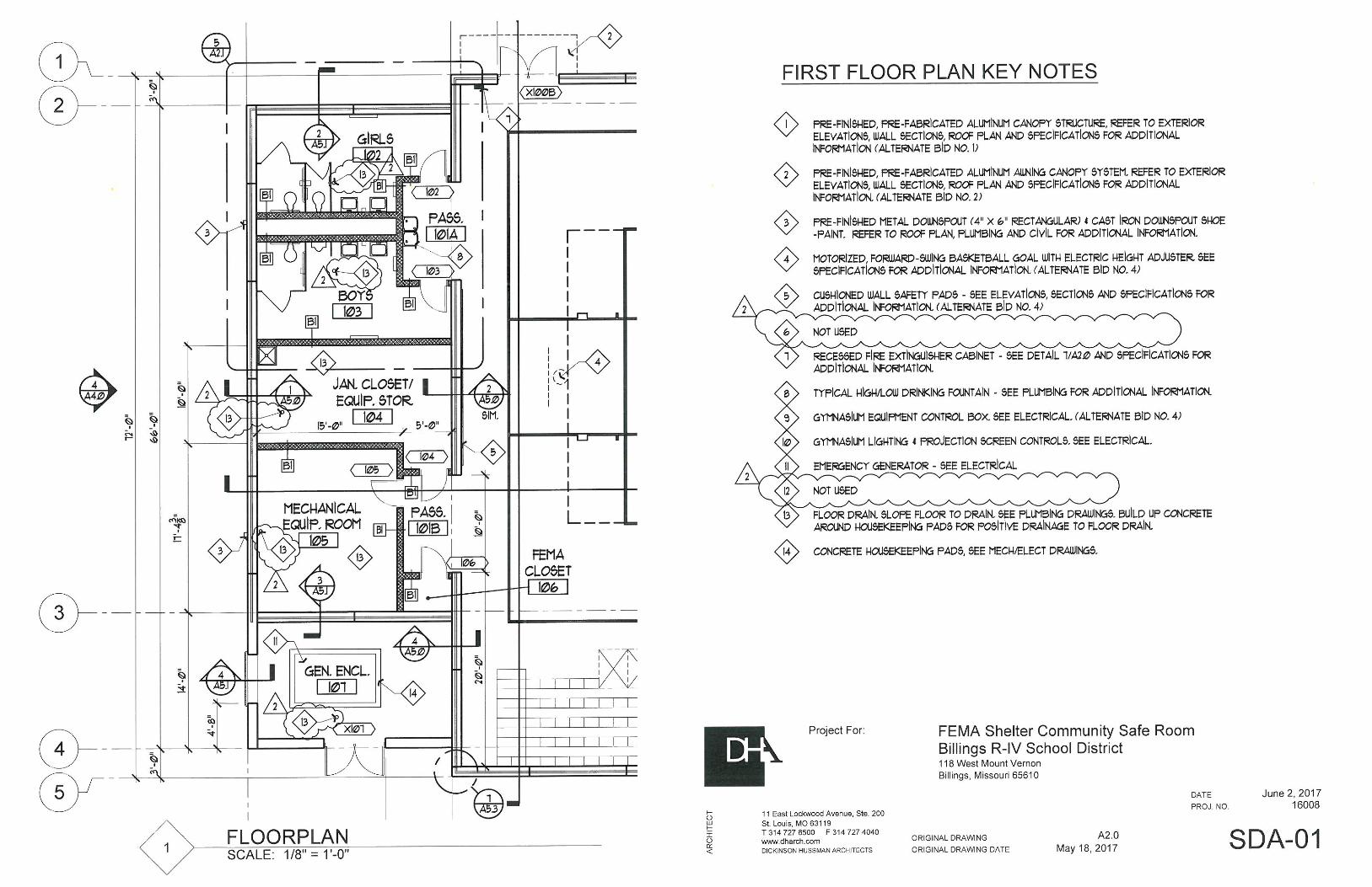
2. Sheet A2.0 – Delete key note 6 and key note 12. Floor drains indicated and called out on the Floor Plan per key note 13 – See attached SDA-01
3. Sheet A3.0 – Key note 19 to be re-labeled to key note 20 near the North scupper along Column line A. Gas piping location indicated on the Roof Plan – See attached SDA-02
4. Sheet A4.0 – Gas piping location indicated on the Exterior Elevation (West) – See attached SDA-03
5. Sheet A6.0 – Delete key note 6 and remove the roof hatch from the Reflected Ceiling Plan. Key note 4 to be re-labeled as key note 5 in both Room 104 and Room 105 on the Reflected Ceiling Plan. – See attached SDA-04
6. Sheet A9.1 – Revise the Room Finish Schedule / Room Finish Schedule (Alternate Bid) – See attached SDA-05
7. Sheet A9.1 – Revise Finish Specification List – See attached SDA-06 ELECTRICAL DRAWING ADDENDUM: See attached from G&W Engineering Corporation dated 06/02/2017 ATTACHMENTS: 1. Supplemental Architectural Drawings (6 Pages)
2. Specification Section 09250 – Gypsum Board (8 Pages)
3. Alco Height Adjuster Specification (1 Page)
4. G&W Engineering Corporation Addendum No. 2 (3 Pages)
END OF ADDENDUM 2


GYPSUM BOARD 09250 - 1
SECTION 09250 - GYPSUM BOARD
PART 1 - GENERAL
1.1 SUMMARY
A. This Section includes the following:
1. Interior gypsum board.
2. Exterior gypsum board for ceilings and soffits.
3. Exterior aluminum vents for ceilings and soffits.
4. Metal suspension system for ceilings and soffits.
1.2 SUBMITTALS
A. Product Data: For each type of product indicated.
B. Samples: For the following products:
1. Trim Accessories: Full-size Sample in 12-inch- long length for each trim accessory
indicated.
PART 2 - PRODUCTS
2.1 PERFORMANCE REQUIREMENTS
1. Fire-Resistance-Rated Assemblies: For fire-resistance-rated assemblies, provide materials
and construction identical to those tested in assembly indicated according to ASTM E
119 by an independent testing agency.
2. Interior suspended ceilings and soffits: Maximum deflection of l/360 of distance between
supports.
3. Exterior soffits: Withstand minimum positive and negative pressure of 20 psf with
maximum deflection of l/360 of distance between supports.
4. Nonstructural components that are permanently attached to structures and their support
attachments, shall be designed and constructed to resist the effects of earthquake motions
in accordance to local jurisdiction.
2.2 INTERIOR GYPSUM BOARD
A. General: Complying with ASTM C 36/C 36M or ASTM C 1396/C 1396M, as applicable to
type of gypsum board indicated and whichever is more stringent.
1. Manufacturers: Subject to compliance with requirements, provide products by one of the
following:
a. American Gypsum Co.
GYPSUM BOARD 09250 - 2
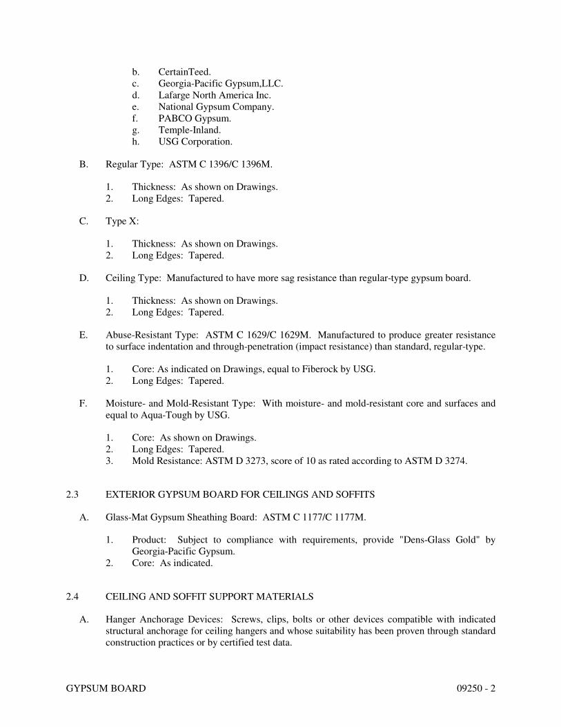
b. CertainTeed.
c. Georgia-Pacific Gypsum,LLC.
d. Lafarge North America Inc.
e. National Gypsum Company.
f. PABCO Gypsum.
g. Temple-Inland.
h. USG Corporation.
B. Regular Type: ASTM C 1396/C 1396M.
1. Thickness: As shown on Drawings.
2. Long Edges: Tapered.
C. Type X:
1. Thickness: As shown on Drawings.
2. Long Edges: Tapered.
D. Ceiling Type: Manufactured to have more sag resistance than regular-type gypsum board.
1. Thickness: As shown on Drawings.
2. Long Edges: Tapered.
E. Abuse-Resistant Type: ASTM C 1629/C 1629M. Manufactured to produce greater resistance
to surface indentation and through-penetration (impact resistance) than standard, regular-type.
1. Core: As indicated on Drawings, equal to Fiberock by USG.
2. Long Edges: Tapered.
F. Moisture- and Mold-Resistant Type: With moisture- and mold-resistant core and surfaces and
equal to Aqua-Tough by USG.
1. Core: As shown on Drawings.
2. Long Edges: Tapered.
3. Mold Resistance: ASTM D 3273, score of 10 as rated according to ASTM D 3274.
2.3 EXTERIOR GYPSUM BOARD FOR CEILINGS AND SOFFITS
A. Glass-Mat Gypsum Sheathing Board: ASTM C 1177/C 1177M.
1. Product: Subject to compliance with requirements, provide "Dens-Glass Gold" by
Georgia-Pacific Gypsum.
2. Core: As indicated.
2.4 CEILING AND SOFFIT SUPPORT MATERIALS
A. Hanger Anchorage Devices: Screws, clips, bolts or other devices compatible with indicated
structural anchorage for ceiling hangers and whose suitability has been proven through standard
construction practices or by certified test data.

GYPSUM BOARD 09250 - 3
B. Powder-Actuated Fasteners in Concrete: Fabricated from corrosion-resistant materials, with
clips or other accessory devices for attaching hangers [and with capability to sustain, without
failure, a load equal to 10x calculated loads].
C. Hangers:
a. Steel wire or rods, sizes to comply with requirements of ASTM C754 for ceiling or soffit
area and loads to be supported.
b. Wire: ASTM A 641, soft, Class 1 galvanized.
c. Rods and flats:
i. Mild steel components.
ii. Finish: Galvanized or painted with rust-inhibitive paint for interior work;
galvanized for exterior work.
D. Framing System:
a. Main runners:
1. Cold-rolled, "C" shaped steel channels, 16 gauge minimum.
2. Finish: Galvanized with G40 hot-dip galvanized coating per ASTM A525 [for exterior work]; galvanized or painted with rust-inhibitive paint for other interior work.
3. Form to required radius at curved ceilings.
b. Cross furring: Hat-shaped steel furring channels, ASTM C645, 7/8 inch high, 25 gauge, galvanized.
c. Furring anchorages: 16 gauge galvanized wire ties, manufacturer's standard wire-type clips, bolts, nails or screws recommended by furring manufacturer and complying with ASTM C754.
d. Provide compression posts and other accessories as required to comply with seismic requirements.
E. Proprietary Framing System:
1. Framing system for gypsum board panels consisting of cold-rolled steel members conforming to ASTM C635, with exposed surfaces finished in manufacturer’s standard enamel paint finish.
2. Components: Main tees, furring cross channels, furring cross tees, and cross tees.
3. Accessories:
a. U-shaped channel molding. b. Galvanized carbon steel (12 ga.) hanger wire.

GYPSUM BOARD 09250 - 4
4. Acceptable product: Equivalent to Drywall Suspension System by USG.
2.5 TRIM ACCESSORIES
A. Interior Trim: ASTM C 1047.
1. Material: Paper-faced galvanized steel sheet.
2. Shapes:
a. Cornerbead.
b. LC-Bead: J-shaped; exposed long flange receives joint compound.
c. L-Bead: L-shaped; exposed long flange receives joint compound.
d. Expansion (control) joint.
B. Exterior Trim: ASTM C 1047.
1. Material: Hot-dip galvanized steel sheet, plastic, or rolled zinc.
2. Shapes:
a. Cornerbead.
b. LC-Bead: J-shaped; exposed long flange receives joint compound.
c. Expansion (Control) Joint: One-piece, rolled zinc with V-shaped slot and
removable strip covering slot opening.
3. Manufacturers: Subject to compliance with requirements, provide products by one of the
following:
a. Fry Reglet Corp.
b. Gordon, Inc.
c. Pittcon Industries.
C. Exterior Vent Louvers for Ceilings and Soffits:
1. Aluminum Vent Louver: Equal to Model DCS-XX-V-300 (thickness as required) as
manufactured by Fry Reglet Corporation. Aluminum shall be 6063 T5 extruded alloy.
a. Finish: Clear Anodized Aluminum
b. Accessories: Insect Screen
c. Reveal Width: 3”
2.6 JOINT TREATMENT MATERIALS
A. General: Comply with ASTM C 475/C 475M.
B. Joint Tape:

GYPSUM BOARD 09250 - 5
1. Interior Gypsum Wallboard: Paper.
2. Exterior Gypsum Soffit Board: Paper.
3. Glass-Mat Gypsum Sheathing Board: 10-by-10 glass mesh.
C. Joint Compound for Interior Gypsum Wallboard: For each coat use formulation that is
compatible with other compounds applied on previous or for successive coats.
1. Prefilling: At open joints, rounded or beveled panel edges, and damaged surface areas,
use setting-type taping compound.
2. Embedding and First Coat: For embedding tape and first coat on joints, fasteners, and
trim flanges, use setting-type taping compound.
a. Use setting-type compound for installing paper-faced metal trim accessories.
3. Fill Coat: For second coat, use setting-type, sandable topping compound.
4. Finish Coat: For third coat, use setting-type, sandable topping compound.
D. Joint Compound for Exterior Applications:
1. Glass-Mat Gypsum Sheathing Board: As recommended by sheathing board
manufacturer.
2.7 AUXILIARY MATERIALS
A. General: Provide auxiliary materials that comply with referenced installation standards and
manufacturer's written recommendations.
B. Steel Drill Screws: ASTM C 1002, unless otherwise indicated.
1. Use screws complying with ASTM C 954 for fastening panels to steel members from
0.033 to 0.112 inch thick.
2. For fastening cementitious backer units, use screws of type and size recommended by
panel manufacturer.
C. Sound Attenuation Blankets: ASTM C 665, Type I (blankets without membrane facing)
produced by combining thermosetting resins with mineral fibers manufactured from rock wool.
Fiberglass batts will not be acceptable. Acceptable products are Therma Fiber, SAFB, Fibrex,
and Roxul.
1. Density: 2.5pcf
2. Flame Spread: 0
3. Smoke Developed: 0
D. Acoustical Joint Sealant: As specified in Division 7 Section “Joint Sealants”.
E. Thermal Insulation: As specified in Division 7 Section "Building Insulation."
F. Vapor Retarder: As specified in Division 7 Section "Building Insulation."

GYPSUM BOARD 09250 - 6
PART 3 - EXECUTION
3.1 METAL SUPPORT INSTALLATION
A. Ceiling and Soffit Support Systems:
1. Secure hangers or rods to structural support by connecting directly to structure where
possible; otherwise connect to inserts, clips or other anchorage devices or fasteners
indicated.
2. Space main runners, hangers and furring according to requirements of ASTM C754,
except as otherwise indicated.
3. Where spacing of structural members, or width of ducts or other equipment, prevents
regular spacing of hangers, provide supplemental hangers and suspension members and
reinforce nearest affected hangers to span extra distance.
4. Attach directly to structural elements only; do not attach to metal deck. Loop hangers
and wire-tie directly or provide anchors or inserts.
5. Install compression posts, splay wires and other accessories as required to comply with
seismic requirements.
6. Extend runners to within 6 inches of walls.
7. Wire-tie or clip furring members to main runners and to other structural supports
indicated. In fire resistance rated assemblies, wire-tie furring members; do not clip.
8. Do not permit furring or runners to contact masonry or concrete walls.
9. Provide 1 inch clearance between furring or runners and abutting walls and partitions.
10. For proprietary framing system, comply with manufacturer's instructions.
3.2 APPLYING AND FINISHING PANELS, GENERAL
A. Comply with ASTM C 840.
B. Examine panels before installation. Reject panels that are wet, moisture damaged, and mold
damaged.
C. Isolate perimeter of gypsum board applied to non-load-bearing partitions at structural
abutments, except floors. Provide 1/4- to 1/2-inch- wide spaces at these locations, and trim
edges with edge trim where edges of panels are exposed. Seal joints between edges and
abutting structural surfaces with acoustical sealant.
3.3 APPLYING INTERIOR GYPSUM BOARD
A. Install interior gypsum board in the following locations:

GYPSUM BOARD 09250 - 7
1. Regular Type: As indicated on Drawings.
2. Type X: As indicated on Drawings.
3. Ceiling Type: As indicated on Drawings.
4. Abuse-Resistant Type: As indicated on Drawings.
5. Moisture- and Mold-Resistant Type: As indicated on Drawings.
3.4 APPLYING EXTERIOR GYPSUM PANELS FOR CEILINGS AND SOFFITS
A. Apply panels perpendicular to supports, with end joints staggered and located over supports.
1. Install with 1/4-inch open space where panels abut other construction or structural
penetrations.
2. Fasten with corrosion-resistant screws.
3.5 INSTALLING TRIM ACCESSORIES
A. General: For trim with back flanges intended for fasteners, attach to framing with same
fasteners used for panels. Otherwise, attach trim according to manufacturer's written
instructions.
B. Control Joints: Install control joints at locations indicated on Drawings and according to
ASTM C 840 and in specific locations approved by Architect for visual effect.
C. Interior Trim: Install in the following locations:
1. Cornerbead: Use at outside corners.
2. LC-Bead: Use at exposed panel edges.
3. L-Bead: Use where indicated.
D. Exterior Trim: Install in the following locations:
1. Cornerbead: Use at outside corners.
2. LC-Bead: Use at exposed panel edges.
3.6 FINISHING GYPSUM BOARD
A. General: Treat gypsum board joints, interior angles, edge trim, control joints, penetrations,
fastener heads, surface defects, and elsewhere as required to prepare gypsum board surfaces for
decoration. Promptly remove residual joint compound from adjacent surfaces.
B. Prefill open joints, rounded or beveled edges, and damaged surface areas.
C. Apply joint tape over gypsum board joints, except those with trim having flanges not intended
for tape.
D. Gypsum Board Finish Levels: Finish panels to levels indicated below:
1. Level 1: Ceiling plenum areas, concealed areas, and where indicated.
2. Level 2: Panels that are substrate for tile.

GYPSUM BOARD 09250 - 8
3. Level 4: At panel surfaces that will be exposed to view, unless otherwise indicated.
a. Primer and its application to surfaces are specified in other Division 9 Sections.
E. Glass-Mat Gypsum Sheathing Board: Finish according to manufacturer's written instructions
for use as exposed soffit board.
3.7 PROTECTION
A. Protect installed products from damage from weather, condensation, direct sunlight,
construction, and other causes during remainder of the construction period.
B. Remove and replace panels that are wet, moisture damaged, and mold damaged.
1. Indications that panels are wet or moisture damaged include, but are not limited to,
discoloration, sagging, or irregular shape.
2. Indications that panels are mold damaged include, but are not limited to, fuzzy or
splotchy surface contamination and discoloration.
END OF SECTION 09250

#BHA-E (Electric) Backboard Height Adjuster Specifications
Provide electric-powered backboard goal height adjustment mechanism equal to the
BHA-E by AALCO Manufacturing Co. of St. Louis, MO. Mechanism shall provide
infinite vertical adjustment of the backboard and goal over a 2’ range (typically 8’ to 10’)
by means of a telescoping tubular steel framework powered by a 120 VAC, 22.5
inch/minute linear actuator having automatic travel cutoff at the up and down limits.
The mechanism shall be configured to mount to most types of ceiling or wall mounted
backstop supports and so constructed as to support goal in a rigid, vibration-free manner
in all positions. Power and up/off/down control shall be supplied by one or more
mechanisms in a gym by means of 50 ft. extension cord and 5 ft. long portable “wand”
equipped with control switch and tipped with a single female receptacle. The electric
actuator of each mechanism shall be equipped with a matching male three prong, 5-15P
plug easily accessible from floor level to the hand-held wand that plugs into any 110 volt
AC electric outlet.
Optional wiring to remote control key switch available upon request.

This addendum narrative forms a part of the Contract Documents and modifies the original Bid Documents dated 05/18/2017.
ELECTRICAL DRAWINGS
SHEET E0.1 A. “Revise” panel schedule for panel “P1” per attached sketch SDE-01.
SHEET E2.0 A. “Revise” drawing per attached sketch SDE-02.
END OF ADDENDUM NO. 2
Date: June 2, 2017Project Number: 2016-0529.00Project Name: Billings – FEMA ShelterFrom: Electrical: Kevin Brown
ADDENDUM NO. 2

PANELBOARD SCHEDULE
DESIGNATION/I.D: P1 TYPE OF PANEL: CIRCUIT BREAKER ** MOUNTING: SURFACE
VOLTAGE: 120 / 208 /3PH-4W BUS SIZE (AMPS): 400 MAIN SWITCH: 400A MCB MAIN RATING AIC 22k
POLES: 3PSN LUGS: STANDARD TOTAL SPACE REQUIRED: 42 NOTES:
SERVICE ENTRANCE RATEDFEEDER: SEE RISER DIAGRAM POWER SOURCE: UTILITY XFMR
C
K
T
#
C/BLOAD (WATTS)
C
L
A
S
S
LOAD DESCRIPTION LOAD DESCRIPTION
C
L
A
S
S
LOAD (WATTS)C/B
C
K
T
#AØ BØ CØ AØ BØ CØ
1 20/1 1500 M1 MOTORIZED BBALL GOAL MOTORIZED BBALL GOAL M1 1500 20/1 2
3 20/1 500 M1 MOTORIZED PROJ. SCREEN REC - GYM PROJECTOR R 500 20/1 4
5 20/1 R SPARE REC - GYM FLOOR NORTH R 360 20/1 6
7 20/1 180 R REC - RTU-1 REC - GYM FLOOR SOUTH R 360 20/1 8
9 25/1 2300 R GIRLS - HAND DRYER REC - GYM FLOOR EAST R 360 20/1 10
11 25/1 2300 R BOYS - HAND DRYER MOTORIZED BLEACHERS M3 865 20/3 12
13 20/1 R SPARE -- M3 865 - 14
15 20/1 R SPARE -- M3 865 - 16
17 20/1 R SPARE SPARE R 20/1 18
19 20/1 R SPARE SPARE R 20/1 20
21 20/1 R SPARE SPARE R 20/1 22
23 20/1 R SPARE SPARE R 20/1 24
25 20/2 1150 H UH-3 SPARE R 20/1 26
27 - 1150 H -- SPARE R 20/1 28
29 30/2 2000 H DWH-1 UH-4 H 2500 30/2 30
31 - 2000 H -- -- H 2500 - 32
33 20/2 1500 H UH-1 UH-2 H 1500 20/2 34
35 - 1500 H -- -- H 1500 - 36
37 175/3 13630 A3 RTU-1 PANEL "EM" XF 6700 100/3 38
39 - 13630 A3 -- -- XF 7150 - 40
41 - 13630 A3 -- -- XF 6480 - 42
TOTALS 18460 19080 19430 11925 10375 11705 TOTALS
CONNECTED LOAD:
(VOLT-AMPERE)90,975VA
NOTES: * PROVIDE LOCK ON DEVICE
** 10,000 A.I.C. RATING UNLESS OTHERWISE SPECIFIED CALC. DEMAND
LOAD AMPERE:231A
CLASS: M1=SINGLE PH MOTOR, M3=3PH MOTOR, M2=2PH MOTOR, L=LIGHTING, R=RECEPTACLE, A1=1PH A/C LOAD, A2=2PH A/C LOAD, A3=3PH A/C
LOAD, H=HEATING, K=KITCHEN; XF=TRANSFORMER-PANEL; SF=SUB-FEED
www.dharch.com
St. Louis, MO 63119
DICKINSON HUSSMAN ARCHITECTS
11 East Lockwood Avenue, Ste. 200
AR
CH
ITE
CT
T 314 727 8500 F 314 727 4040
ORIGINAL DRAWING DATE
ORIGINAL DRAWING
PROJ. NO.
DATE
May 18, 2017
16008
Project For: FEMA Shelter Community Safe RoomBillings R-IV School District118 West Mount Vernon
Billings, Missouri 65610
June 02, 2017
SDE-01E0.1
1
1

WP5
F
155
5
F.A.A.P
9 ab
F
WP
J
17
J J8
18
J
17J
J10
18
P1-6,8,10
21
J
(30/10/3)
20
P1-12,14,161
1
1
C
5
4
3
PARTIAL FLOOR PLAN - POWER & SYSTEMSSCALE: 1/4" = 1'-0"
PLAN NOTES - POWER & SYSTEMS#
N
20. PROVIDE DISCONNECT SWITCH ON WALL FOR MOTORIZED BLEACHERS. MAKE
FINAL CONNECTIONS VIA LOCAL DISCONNECT SWITCH. EXTEND WIRING TO
JUNCTION BOX AS SHOWN. COORDINATE EXACT LOCATION, MOUNTING HEIGHT,
AND REQUIREMENTS WITH EQUIPMENT INSTALLER.
21. PROVIDE JUNCTION BOX MOUNTED AT 60" A.F.F. FOR MOTORIZED BLEACHERS.
COORDINATE EXACT LOCATION, MOUNTING HEIGHT, AND REQUIREMENTS WITH
EQUIPMENT INSTALLER.
1
www.dharch.com
St. Louis, MO 63119
DICKINSON HUSSMAN ARCHITECTS
11 East Lockwood Avenue, Ste. 200
AR
CH
ITE
CT
T 314 727 8500 F 314 727 4040
ORIGINAL DRAWING DATE
ORIGINAL DRAWING
PROJ. NO.
DATE
May 18, 2017
16008
Project For: FEMA Shelter Community Safe RoomBillings R-IV School District118 West Mount Vernon
Billings, Missouri 65610
June 02, 2017
SDE-02E2.0