community & competence - Amann Girrbach · pontic according to the established tooth shape. For...
28
Change, the constant of the future CAD/CAM fabrication of implant-supported bridges in the maxilla and mandible Part 1, Part 2 & Part 3 An article by Master Dental Technician Ralf Bahle, Leutkirch/Germany community & competence The international journal of dental technology Offprint Amann Girrbach AG Herrschaftswiesen 1 6842 Koblach • Austria Phone +43 (5523) 62333-394 Fax +43 (5523) 55990 www.amanngirrbach.com submitted by:
Transcript of community & competence - Amann Girrbach · pontic according to the established tooth shape. For...
Change, the constant of the futureCAD/CAM fabrication of implant-supportedbridges in the maxilla and mandiblePart 1, Part 2 & Part 3
An article by Master Dental Technician Ralf Bahle, Leutkirch/Germany
community & competence
The international journal of dental technology
Offprint
Amann Girrbach AGHerrschaftswiesen 16842 Koblach • AustriaPhone +43 (5523) 62333-394Fax +43 (5523) 55990www.amanngirrbach.com
submitted by:

C A D 4 p r a c t i c e
2 dental dialogue 11TH EDITION 2010 ©
Change,the constantof the futureOnly a few years ago many people smiled wearily as some visionaries stated that the computer wouldmake inroads into dental technology. Today this initial scepticism is really no longer a topic of discussion,as CAD/CAM technology has become well-established – in laboratories, milling centres, dental practicesand hospitals. It cannot be claimed, however, that the CAD/CAM technique has become standard practice.It has certainly made its mark and still remains an interesting technique that is subject to constant change.In this article Master Dental Technician Ralf Bahle provides an insight into computer-aided dental technologyin 2010. Using an actual patient case he demonstrates in three parts the opportunities offered by selectiveuse of this technique.
An article by Master Dental Technician Ralf Bahle, Leutkirch/Germany
CAD/CAM fabrication of implant-supported bridges in the maxilla and mandible – Part 1
dd T E C H N I Q U E
Indices
• CAD/CAM• Implant prosthetics• Silicone index• Transfer die• Wax-up
Category
System-relatedSeries of articles
Overview
5/10 Part 16/10 Part 27/10 Part 3
Introduction
As early as the 1990s, futurologists pre-dicted that the most constant feature inour society in years to come would bechange. This statement is now reality.We are now witnessing an increasinglyfast pace in our society, which is sup-ported by the fact that technical knowl-edge doubles about every two years. This is most clearly illustrated by com-puter technology. The computer that wepurchase today is already obsolete thenext day, as there is another new modelwith an even larger storage capacity and amore extensive range of functions.
In the car industry and in engineering itcan be seen that ever more complex andefficient machines are increasingly mak-ing humans dispensable in the digitalage. What is required now is not purely
manual strength and skill, but our com-puter know-how.Only a few years ago many technicianssmiled wearily as some visionaries statedthat this trend would also make inroadsinto dental technology.Today these sceptics have been provedwrong. The arrival of CAD/CAM tech-nology many years ago and the constantfurther development of this technologyhave also become established in thisbranch.The following first part of a three-partcase report presents the digital designand laboratory realisation of implant-supported rehabilitation in all four quad-rants. It was important to plan and realisethe restoration and consequently all fur-ther analogue or digital working stageson the basis of a wax-up, which was fab-ricated right at the beginning of the pro-cedure. This prevents the situation of
duplicated or additional working stages.The maximum possible cost-effective-ness and optimal result with regard toquality are therefore guaranteed.
Case
As extensive full-mouth rehabilitationsare part of the day-to-day business ofMaster Dental Technician Ralf Bahle, he isvery happy that the concept installed inhis laboratory that ensures reliable, effi-cient and reproducible planning and re-alisation of this type of restoration is moreefficient and therefore more cost-effectivedue to the digital working stages. Preciseplanning at the beginning of the prosthet-ic restoration makes several design andfabrication stages possible with a singleapplication of craftsmanship. The restora-tion can be digitally generated and thenmilled in the laboratory as in a type of
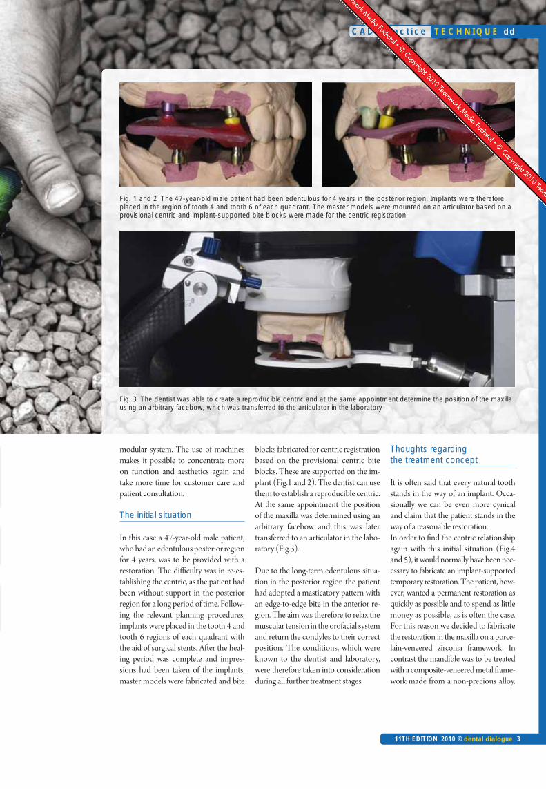
Fig. 1 and 2 The 47-year-old male patient had been edentulous for 4 years in the posterior region. Implants were thereforeplaced in the region of tooth 4 and tooth 6 of each quadrant. The master models were mounted on an articulator based on aprovisional centric and implant-supported bite blocks were made for the centric registration
modular system. The use of machinesmakes it possible to concentrate moreon function and aesthetics again andtake more time for customer care andpatient consultation.
The initial situation
In this case a 47-year-old male patient,who had an edentulous posterior regionfor 4 years, was to be provided with arestoration. The difficulty was in re-es-tablishing the centric, as the patient hadbeen without support in the posteriorregion for a long period of time. Follow-ing the relevant planning procedures,implants were placed in the tooth 4 andtooth 6 regions of each quadrant withthe aid of surgical stents. After the heal-ing period was complete and impres-sions had been taken of the implants,master models were fabricated and bite
blocks fabricated for centric registrationbased on the provisional centric biteblocks. These are supported on the im-plant (Fig.1 and 2). The dentist can usethem to establish a reproducible centric.At the same appointment the positionof the maxilla was determined using anarbitrary facebow and this was latertransferred to an articulator in the labo-ratory (Fig.3).
Due to the long-term edentulous situa-tion in the posterior region the patienthad adopted a masticatory pattern withan edge-to-edge bite in the anterior re-gion. The aim was therefore to relax themuscular tension in the orofacial systemand return the condyles to their correctposition. The conditions, which wereknown to the dentist and laboratory,were therefore taken into considerationduring all further treatment stages.
Thoughts regarding the treatment concept
It is often said that every natural toothstands in the way of an implant. Occa-sionally we can be even more cynicaland claim that the patient stands in theway of a reasonable restoration. In order to find the centric relationshipagain with this initial situation (Fig.4and 5), it would normally have been nec-essary to fabricate an implant-supportedtemporary restoration. The patient, how-ever, wanted a permanent restoration asquickly as possible and to spend as littlemoney as possible, as is often the case.For this reason we decided to fabricatethe restoration in the maxilla on a porce-lain-veneered zirconia framework. Incontrast the mandible was to be treatedwith a composite-veneered metal frame-work made from a non-precious alloy.
C A D 4 p r a c t i c e
11TH EDITION 2010 © dental dialogue 3
T E C H N I Q U E dd
Fig. 3 The dentist was able to create a reproducible centric and at the same appointment determine the position of the maxillausing an arbitrary facebow, which was transferred to the articulator in the laboratory
Any changes in centric or overloadingcould therefore be compensated for byspecific removal or addition of compos-ite and adjustment at a later stage. At thesame time we had fabricated a tempo-rary bridge with a metal strengthenerfrom tooth 21 to tooth 23, as tooth 21was lost after placement of the posteriorimplants. An implant was placed in theregion of tooth 21 four months later.
The wax prototype
To ensure the model could be securelyplaced in the Ceramill Motion unit wefabricated Giroform sectioned models,which we articulated using the relevantsplit-cast bases. The sectioned modelswere only sawn at the necessary areas tocompensate for the shrinkage of thedental stone (Fig. 6).All other saw cuts were only made afterthe first scan of the model. This avoidsany potential inaccuracies.An appropriate set of Creapearl dentureteeth was duplicated using 9:1 siliconefor efficiency during the subsequent
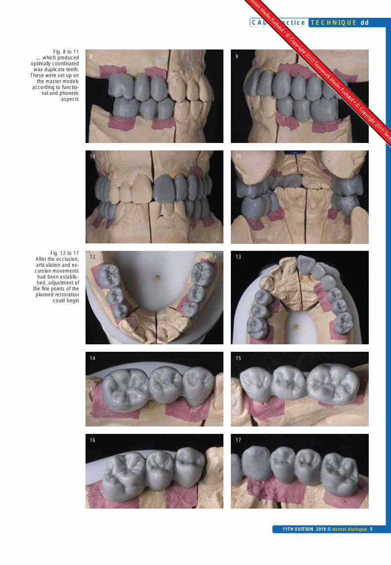
procedure. The hollow moulds pro-duced could be continually filled withwax. In this way we reproduced beauti-ful tooth shapes that were optimally co-ordinated with one another (Fig. 7).The cooled wax teeth could be shapedto set them up on the master model ac-cording to functional facial aspects(Fig. 8 to 11).
After the optimal occlusion, articulationand excursion movements were estab-lished (Fig. 12 to 17), we were able tofocus on the fine points of the plannedimplant prosthetic restoration. We werenow in the position to determine theemergence profile as well an accuratepontic according to the established toothshape. For this we drew the margin of theclinical tooth crown on the model usinga felt-tip pen (Fig. 18).
It is important that the margin is drawnbefore the wax pattern is sprayed withscan spray. Otherwise the felt-tip penwill not be able to draw properly on themodel (Fig. 19 and 20).
The scan spray is required to prevent re-flections on the wax surface. Reflectionsare not recognised by the scanner or aremisinterpreted. They produce virtual“holes” in the 3D image.
The upper master model was thenmounted in the size 300 scanner. Themodel was securely retained in the scan-ner using the split-cast base plates of theGiroform models (Fig. 21). We have lo-cated the CAD/CAM technology in aseparate room, as in our opinion thistype of laboratory work does not fit intothe routine working environment. Inaddition the precision technology re-quires as far as possible a certain degreeof cleanliness and standardised condi-tions (Fig. 22a).
The situation scan
Before the model could be scanned, afile card of the overall situation first hadto be created in the software. Data suchas the patient name, tooth shade, designas well as the individual materials that
C A D 4 p r a c t i c e
4 dental dialogue 11TH EDITION 2010 ©
dd T E C H N I Q U E
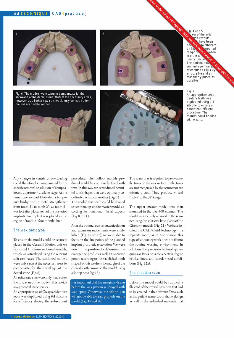
Fig. 4 and 5In view of the initial situation it would normally have beennecessary to fabricatean implant-supportedtemporary restorationin order to find thecentric relation again.The patient, however,wanted a permanentrestoration as quicklyas possible and asreasonably priced aspossible
Fig. 7An appropriate set ofdenture teeth wasduplicated using 9:1silicone to ensure aconsistent, efficientprocedure. Themoulds could be filledwith wax, …
Fig. 6 The models were sawn to compensate for the shrinkage of the dental stone. Only at the necessary areas,however, as all other saw cuts would only be made afterthe first scan of the model
4 5
C A D 4 p r a c t i c e
11TH EDITION 2010 © dental dialogue 5
T E C H N I Q U E dd
Fig. 8 to 11… which produced
optimally coordinatedwax duplicate teeth.
These were set up onthe master models
according to functio-nal and phonetic
aspects
Fig. 12 to 17After the occlusion,articulation and ex-cursion movementshad been establis-hed, adjustment of
the fine points of theplanned restoration
could begin
98
10 11
12 13
14 15
16 17

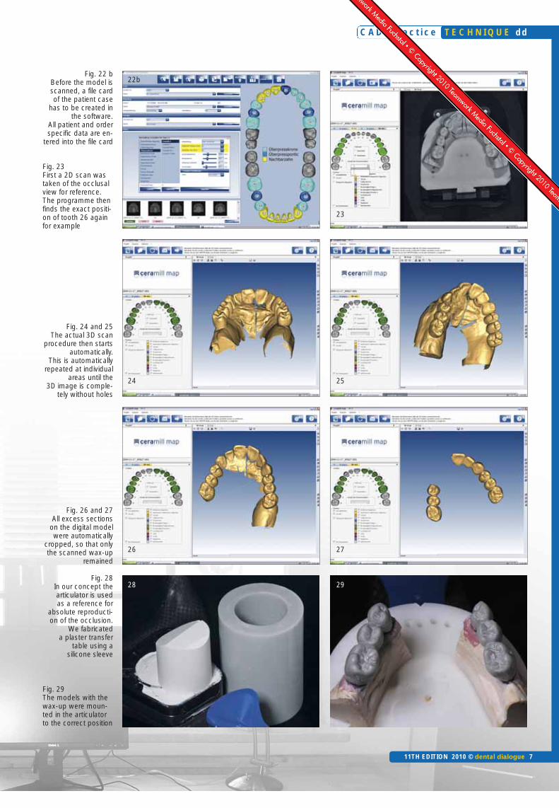
have been used are stored in the filecard. It has to be filled out accurately, sothat the milling order can be correctlyprocessed at a later stage (Fig. 22b).
First a 2D scan was taken of the occlusalview, so that the predefined dental archin the programme could be adapted tothe actual dental arch on the model. Theprogramme then finds the exact positionof tooth 26 again for example (Fig. 23).
Scanning then starts automatically andis repeated at individual areas until the 3Dimage is displayed completely withoutholes (Fig. 24 and 25). After scanning, allexcess sections are cropped, so that onlythe scanned wax-up remains (Fig. 26and 27). This working stage forms animportant basis for all further workingstages and is essential for the spatial vi-sualisation of the planned restorations.
Back in the analogue world
After scanning all wax prototypes –which must be completed at this timeand no later – first we fixed in clear sili-cone the anatomical shapes that werefabricated in wax for the lower bridgesas well as the upper anterior restoration,
which was to be initially fitted with a tem-porary restoration. The articulator wasused as a reference to ensure absolutelyaccurate reproduction of the occlusion.Using special silicone sleeves plaster ta-bles were fabricated at this stage (Fig. 28).The wax-ups were then fixed in the cor-rect position in the lower jaw (Fig. 29).
C A D 4 p r a c t i c e
6 dental dialogue 11TH EDITION 2010 ©
dd T E C H N I Q U E
Fig. 18 The emergence profile of theplanned implant crowns as well as theexact pontic were drawn on the model
Fig. 19 and 20 The drawing should be made before the wax pattern is sprayedwith scan spray The scan spray makes the surface matt and prevents reflectionsimpairing the scan result
Fig. 21 The master models can be securely mounted in the scanner usingthe split cast base plates of the Giroformmodel system
Fig. 22 a We have located our CAD/CAM technology in a separate room. In ouropinion this type of laboratory work does not fit into the routine working environment.A positive side effect: the digital workplace remains clean
Product
Articulator system CAD/CAM system, Inhouse FacebowImplant system Model stoneModel system Sculpting waxDenture teeth
Scan spray Silicone, clearSilicone sleeve
Gingival mask Centric material
Name
ArtexCeramill MotionArtex facebow Screw-Line AlpenrockGiroform SystemGEOCreapearl, Dynamicline, designed by D. SchulzCeramill Scanmarker–Silicone sleeve, large(Creation CP accessories)GumQuickZetatray LC
Manufacturer/DistributionAmannGirrbachAmannGirrbachAmannGirrbachCamlogAmannGirrbachAmannGirrbachRenfertCreation Willi Geller/AmannGirrbachAmannGirrbachDreveCreation Willi Geller/AmannGirrbachDreveZhermack
Product list
C A D 4 p r a c t i c e
11TH EDITION 2010 © dental dialogue 7
T E C H N I Q U E dd
Fig. 22 bBefore the model isscanned, a file cardof the patient case
has to be created inthe software.
All patient and orderspecific data are en-
tered into the file card
Fig. 23First a 2D scan wastaken of the occlusalview for reference.The programme thenfinds the exact positi-on of tooth 26 againfor example
Fig. 24 and 25The actual 3D scan
procedure then startsautomatically.
This is automaticallyrepeated at individual
areas until the3D image is comple-
tely without holes
Fig. 26 and 27All excess sections
on the digital modelwere automatically
cropped, so that onlythe scanned wax-up
remained
Fig. 28In our concept the articulator is used as a reference for
absolute reproducti-on of the occlusion.
We fabricated a plaster transfer
table using a silicone sleeve
Fig. 29The models with thewax-up were moun-ted in the articulatorto the correct position
28 29
26 27
24 25
22b
23
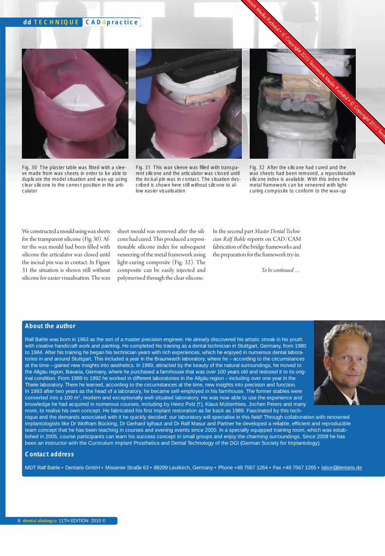
We constructed a mould using wax sheetsfor the transparent silicone (Fig. 30). Af-ter the wax mould had been filled withsilicone the articulator was closed untilthe incisal pin was in contact. In Figure31 the situation is shown still withoutsilicone for easier visualisation. The wax
sheet mould was removed after the sili-cone had cured. This produced a reposi-tionable silicone index for subsequentveneering of the metal framework usinglight-curing composite (Fig. 32). Thecomposite can be easily injected andpolymerised through the clear silicone.
In the second part Master Dental Techni-cian Ralf Bahle reports on CAD/CAMfabrication of the bridge frameworks andthe preparation for the framework try-in.
To be continued …
C A D 4 p r a c t i c e
8 dental dialogue 11TH EDITION 2010 ©
dd T E C H N I Q U E
About the author
Ralf Bahle was born in 1963 as the son of a master precision engineer. He already discovered his artistic streak in his youthwith creative handicraft work and painting. He completed his training as a dental technician in Stuttgart, Germany, from 1980to 1984. After his training he began his technician years with rich experiences, which he enjoyed in numerous dental labora-tories in and around Stuttgart. This included a year in the Braunwarth laboratory, where he – according to the circumstancesat the time – gained new insights into aesthetics. In 1989, attracted by the beauty of the natural surroundings, he moved tothe Allgäu region, Bavaria, Germany, where he purchased a farmhouse that was over 100 years old and restored it to its orig-inal condition. From 1989 to 1992 he worked in different laboratories in the Allgäu region – including over one year in theThiele laboratory. There he learned, according to the circumstances at the time, new insights into precision and function. In 1993 after two years as the head of a laboratory, he became self-employed in his farmhouse. The former stables wereconverted into a 100 m2, modern and exceptionally well-situated laboratory. He was now able to use the experience andknowledge he had acquired in numerous courses, including by Heinz Polz (†), Klaus Mütterthies, Jochen Peters and manymore, to realise his own concept. He fabricated his first implant restoration as far back as 1989. Fascinated by this tech-nique and the demands associated with it he quickly decided: our laboratory will specialise in this field! Through collaboration with renowned implantologists like Dr Wolfram Bücking, Dr Gerhard Iglhaut and Dr Ralf Masur and Partner he developed a reliable, efficient and reproducibleteam concept that he has been teaching in courses and evening events since 2000. In a specially equipped training room, which was estab-lished in 2005, course participants can learn his success concept in small groups and enjoy the charming surroundings. Since 2008 he hasbeen an instructor with the Curriculum Implant Prosthetics and Dental Technology of the DGI (German Society for Implantology).
Contact address
MDT Ralf Bahle • Dentaris GmbH • Missener Straße 63 • 88299 Leutkirch, Germany • Phone +49 7567 1264 • Fax +49 7567 1265 • [email protected]
Fig. 30 The plaster table was fitted with a slee-ve made from wax sheets in order to be able toduplicate the model situation and wax-up usingclear silicone to the correct position in the arti-culator
Fig. 31 This wax sleeve was filled with transpa-rent silicone and the articulator was closed untilthe incisal pin was in contact. The situation des-cribed is shown here still without silicone to al-low easier visualisation
Fig. 32 After the silicone had cured and thewax sheets had been removed, a repositionablesilicone index is available. With this index themetal framework can be veneered with light-curing composite to conform to the wax-up
C A D 4 p r a c t i c e
11TH EDITION 2010 © dental dialogue 9
T E C H N I Q U E dd
Change,the constantof the futureWhen people talk about computer-aided dental technology nowadays, the term future is used all too oftenin connection with the subject. But this is incorrect, as CAD/CAM has fully arrived and has become an established part of dental technology and prosthetic reconstructive dentistry. Master Dental TechnicianRalf Bahle – well-known for numerous, more technical manual publications – demonstrates in this three-part article (an actual patient case) how he integrated CAD/CAM technology logically into his establishedand successful work routine. After the wax-up had been manually waxed up and digitised in the first part,the author describes in this part how the designs via CAD/CAM are converted into the relevant frameworkmaterial. The framework try-in at the end of this article demonstrates, however, that ultimately the stan-dard, manual processes are continually required.
An article by Master Dental Technician Ralf Bahle, Leutkirch/Germany
CAD/CAM fabrication of implant-supported bridges in the maxilla and mandible – Part 2
Indices
• CAD/CAM• Implant prosthetics• Framework design• Function• Matching• Multiple scan• Silicone index• Transfer die• Wax-up• Zirconia
Category
System-related Series of articles
What has happened so far
As extensive full-mouth rehabilitations,as described in this article, are part of theday-to-day business of the author, he isvery pleased that CAD/CAM technolo-gy could be seamlessly and efficientlyintegrated into his existing laboratoryconcept. Master Dental Technician RalfBahle is of the opinion that precise plan-ning is required at the beginning of pros-thetic treatment to ensure efficient, repro-ducible realisation of a restoration. Thismakes several subsequent design and fab-rication stages possible due to a single ap-plication of craftsmanship at the begin-ning of a laboratory restoration.
After the wax prototypes had beenscanned (cf. dental dialogue 5/10), animpression of the wax anatomical forms
for the lower and upper restorations wastaken using clear silicone. The articula-tor is used as a reference to ensure ab-solutely accurate reproduction of thewax occlusion. Due to the fact that theclear silicone duplicate mould is syn-chronised with the individually adjustedarticulator, all of the duplicated struc-tures have the same occlusal relationshipas the fully anatomical wax-ups. Light-curing composite can now simply be in-jected into the silicone index, which isfixed in position in the articulator, andpolymerised through the index for ve-neering the metal framework.
In the following the author explainsCAD/CAM fabrication of the bridgeframeworks for the permanent restora-tion as well as the preparation for theframework try-in.
Design and fabrication of the framework structures
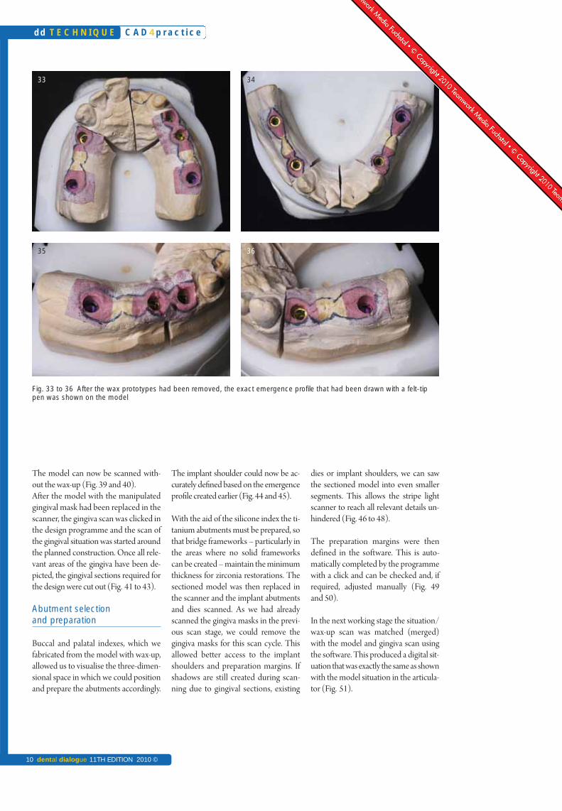
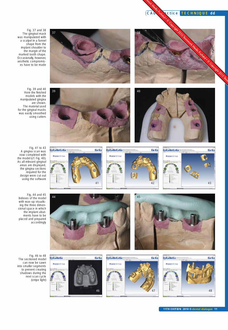
After removal of the wax prototypes, theexact emergence profile that had beendrawn with a felt-tip pen is shown on themodel. We use these outlines for accu-rately shaping the soft gingival mask(Fig. 33 to 36). The gingival mask is nowopened in a funnel shape using a sharpscalpel – from the implant shoulder tothe margin of the marked anatomicaltooth shape (Fig. 37 to 39). Occasional-ly the required details cannot be main-tained, so that compromises have to bemade with the aesthetics. The ponticcan also be contoured to the shape of anovate pontic [1-6]. After smoothing ofthe soft tissue with relevant cutters, ma-nipulation of the emergence profile iscomplete.
Overview
5/10 Part 16/10 Part 27/10 Part 3
C A D 4 p r a c t i c e
10 dental dialogue 11TH EDITION 2010 ©
dd T E C H N I Q U E
Fig. 33 to 36 After the wax prototypes had been removed, the exact emergence profile that had been drawn with a felt-tippen was shown on the model
33 34
35 36
The model can now be scanned with-out the wax-up (Fig. 39 and 40). After the model with the manipulatedgingival mask had been replaced in thescanner, the gingiva scan was clicked inthe design programme and the scan ofthe gingival situation was started aroundthe planned construction. Once all rele-vant areas of the gingiva have been de-picted, the gingival sections required forthe design were cut out (Fig. 41 to 43).
Abutment selection and preparation
Buccal and palatal indexes, which wefabricated from the model with wax-up,allowed us to visualise the three-dimen-sional space in which we could positionand prepare the abutments accordingly.
The implant shoulder could now be ac-curately defined based on the emergenceprofile created earlier (Fig. 44 and 45).
With the aid of the silicone index the ti-tanium abutments must be prepared, sothat bridge frameworks – particularly inthe areas where no solid frameworkscan be created – maintain the minimumthickness for zirconia restorations. Thesectioned model was then replaced inthe scanner and the implant abutmentsand dies scanned. As we had alreadyscanned the gingiva masks in the previ-ous scan stage, we could remove thegingiva masks for this scan cycle. Thisallowed better access to the implantshoulders and preparation margins. Ifshadows are still created during scan-ning due to gingival sections, existing
dies or implant shoulders, we can sawthe sectioned model into even smallersegments. This allows the stripe lightscanner to reach all relevant details un-hindered (Fig. 46 to 48).
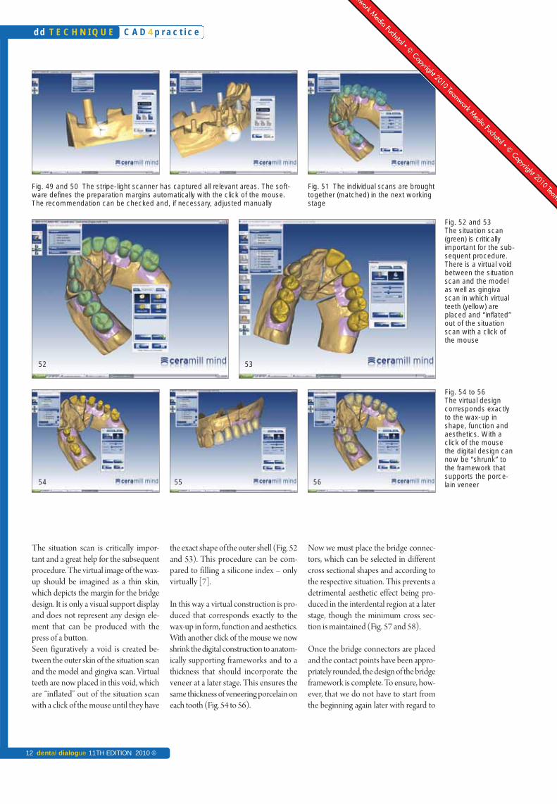
The preparation margins were then defined in the software. This is auto-matically completed by the programmewith a click and can be checked and, ifrequired, adjusted manually (Fig. 49and 50).
In the next working stage the situation/wax-up scan was matched (merged)with the model and gingiva scan usingthe software. This produced a digital sit-uation that was exactly the same as shownwith the model situation in the articula-tor (Fig. 51).
C A D 4 p r a c t i c e
11TH EDITION 2010 © dental dialogue 11
T E C H N I Q U E dd
Fig. 37 and 38 The gingival mask
was manipulated witha scalpel in a funnel
shape from the implant shoulder to
the margin of themarked tooth shape.
Occasionally, however,aesthetic compromis-
es have to be made
Fig. 39 and 40 Here the finishedmodels with the
manipulated gingivaare shown.
The material used for the gingival maskswas easily smoothed
using cutters
Fig. 41 to 43 A gingiva scan was
now completed withthe model (cf. Fig. 40).As all relevant gingival
areas are displayed,the gingiva sections
required for the design were cut out
using the software
Fig. 44 and 45Indexes of the modelwith wax-up visualis-ing the three dimen-
sional space in whichthe implant abut-ments have to be
placed and preparedaccordingly
Fig. 46 to 48 The sectioned model
can now be sawn into smaller segments
to prevent creatingshadows during the
next scan cycle(stripe light)
37 38
39 40
44 45
46 47 48
41 42 43
C A D 4 p r a c t i c e
12 dental dialogue 11TH EDITION 2010 ©
dd T E C H N I Q U E
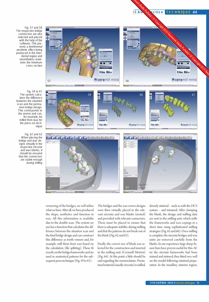
Now we must place the bridge connec-tors, which can be selected in differentcross sectional shapes and according tothe respective situation. This prevents adetrimental aesthetic effect being pro-duced in the interdental region at a laterstage, though the minimum cross sec-tion is maintained (Fig. 57 and 58).
Once the bridge connectors are placedand the contact points have been appro-priately rounded, the design of the bridgeframework is complete. To ensure, how-ever, that we do not have to start fromthe beginning again later with regard to
the exact shape of the outer shell (Fig. 52and 53). This procedure can be com-pared to filling a silicone index – onlyvirtually [7].
In this way a virtual construction is pro-duced that corresponds exactly to thewax-up in form, function and aesthetics.With another click of the mouse we nowshrink the digital construction to anatom-ically supporting frameworks and to athickness that should incorporate theveneer at a later stage. This ensures thesame thickness of veneering porcelain oneach tooth (Fig. 54 to 56).
The situation scan is critically impor-tant and a great help for the subsequentprocedure. The virtual image of the wax-up should be imagined as a thin skin,which depicts the margin for the bridgedesign. It is only a visual support displayand does not represent any design ele-ment that can be produced with thepress of a button.Seen figuratively a void is created be-tween the outer skin of the situation scanand the model and gingiva scan. Virtualteeth are now placed in this void, whichare “inflated” out of the situation scanwith a click of the mouse until they have
Fig. 49 and 50 The stripe-light scanner has captured all relevant areas. The soft-ware defines the preparation margins automatically with the click of the mouse.The recommendation can be checked and, if necessary, adjusted manually
Fig. 51 The individual scans are broughttogether (matched) in the next workingstage
54 55
52
Fig. 52 and 53The situation scan(green) is critically important for the sub-sequent procedure.There is a virtual voidbetween the situationscan and the modelas well as gingivascan in which virtualteeth (yellow) areplaced and “inflated”out of the situationscan with a click ofthe mouse
Fig. 54 to 56 The virtual designcorresponds exactlyto the wax-up inshape, function andaesthetics. With aclick of the mousethe digital design cannow be “shrunk” tothe framework thatsupports the porce-lain veneer
53
56
C A D 4 p r a c t i c e
11TH EDITION 2010 © dental dialogue 13
T E C H N I Q U E dd
Fig. 57 and 58 The respective bridge
connectors are alsoselected and placedwith the help of thesoftware. This pre-vents a detrimental
aesthetic effect beingproduced in the inter-
dental region andnevertheless main-tains the minimum
cross section
Fig. 59 to 61The system calcu-lates the difference
between the situationscan and the perma-
nent bridge design.This corresponds tothe veneer and can,
for example, bemilled from wax forthe press-on tech-
nique
Fig. 62 and 63 When placing the
bridge and wax de-signs virtually in therespective zirconiaand wax blanks, itshould be ensured
that the connectorsare stable enough
during milling
60 61
63
58
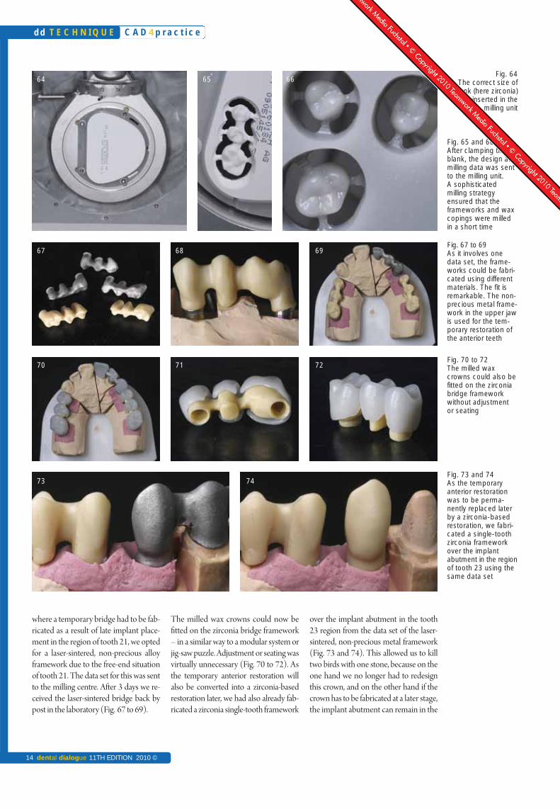
densely sintered – such as with the DCSsystem – and trimmed. After clampingthe blank, the design and milling dataare sent to the milling unit, which millsthe frameworks and wax copings in ashort time using sophisticated millingstrategies (Fig. 65 and 66). Once millingis complete, the zirconia bridges and waxunits are removed carefully from theblanks. In our experience large sharp fis-sure burs have proven useful for this. Af-ter the zirconia frameworks had beenstained and sintered, they fitted very wellon the model following minimal prepa-ration. In the maxillary anterior region,
The bridges and the wax crown designswere then virtually placed in the rele-vant zirconia and wax blanks (nested)and provided with relevant connectors.These must be placed to ensure thatthere is adequate stability during millingand that the patterns do not break out ofthe blank (Fig. 62 and 63).
Finally, the correct size of blank was se-lected for the construction and insertedin the milling unit (Ceramill Motion)(Fig. 64). At this point a little should besaid regarding the nomenclature. Presin-tered material (usually zirconia) is milled,
veneering of the bridges, we will utilisewhat we have. After all, we have producedthe shape, aesthetics and function inwax. All this information is availabledue to the double scan. The system weuse has a function that calculates the dif-ference between the situation scan andthe final bridge design and can constructthis difference as tooth veneers and, forexample, mill them from wax based onthe calculation (file splitting). These fitexactly on the bridge frameworks and areused as anatomical patterns for the sub-sequent press technique (Fig. 59 to 61).
59
62
57
C A D 4 p r a c t i c e
14 dental dialogue 11TH EDITION 2010 ©
dd T E C H N I Q U E
64
67 68
70 71
73
65
over the implant abutment in the tooth23 region from the data set of the laser-sintered, non-precious metal framework(Fig. 73 and 74). This allowed us to killtwo birds with one stone, because on theone hand we no longer had to redesignthis crown, and on the other hand if thecrown has to be fabricated at a later stage,the implant abutment can remain in the
The milled wax crowns could now befitted on the zirconia bridge framework– in a similar way to a modular system orjig-saw puzzle. Adjustment or seating wasvirtually unnecessary (Fig. 70 to 72). Asthe temporary anterior restoration willalso be converted into a zirconia-basedrestoration later, we had also already fab-ricated a zirconia single-tooth framework
where a temporary bridge had to be fab-ricated as a result of late implant place-ment in the region of tooth 21, we optedfor a laser-sintered, non-precious alloyframework due to the free-end situationof tooth 21. The data set for this was sentto the milling centre. After 3 days we re-ceived the laser-sintered bridge back bypost in the laboratory (Fig. 67 to 69).
Fig. 65 and 66 After clamping theblank, the design andmilling data was sentto the milling unit. A sophisticatedmilling strategy ensured that theframeworks and waxcopings were milledin a short time
Fig. 67 to 69 As it involves one data set, the frame-works could be fabri-cated using differentmaterials. The fit isremarkable. The non-precious metal frame-work in the upper jawis used for the tem-porary restoration ofthe anterior teeth
Fig. 70 to 72The milled waxcrowns could also befitted on the zirconiabridge frameworkwithout adjustment or seating
Fig. 73 and 74 As the temporary anterior restorationwas to be perma-nently replaced laterby a zirconia-basedrestoration, we fabri-cated a single-toothzirconia frameworkover the implantabutment in the regionof tooth 23 using thesame data set
Fig. 64The correct size of
blank (here zirconia)was inserted in the
milling unit
69
72
74
66
C A D 4 p r a c t i c e
11TH EDITION 2010 © dental dialogue 15
T E C H N I Q U E dd
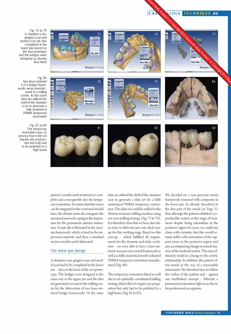
Fig. 81 to 83 The temporary
restoration was soprecise that it did notrequire any prepara-
tion but only had to be polished to a
high lustre
Fig. 80 Two laser-sintered
CrCo bridge frame-works were manufac-
tured in a milling centre. At the sametime we utilised theshell of the situationscan to generate a
fully anatomical PMMA temporary
restoration
Fig. 75 to 79 A situation scan, gingiva scan and
model scan are alsocompleted in the
lower jaw based onthe wax prototype
and the bridges weredesigned as already
described
76 77
79 80
82 83
We decided on a non-precious metalframework veneered with composite inthe lower jaw. As already described inthe first part of the article (cf. Page 3),that although the patient exhibited a re-producible centric at this stage of treat-ment despite being edentulous in theposterior region for years, we could notclaim with certainty that this would re-main stable with restoration of the sup-port zones in the posterior region andany accompanying change in muscle ten-sion of the orofacial system. This may ul-timately result in a change to the centricrelationship. In addition, the patient of-ten stands in the way of a reasonablerestoration. We therefore have to followthe wishes of the patient and – againstour established concept – fabricate apermanent restoration right away due tohis professional occupation.
time we utilised the shell of the situationscan to generate a data set for a fullyanatomical PMMA temporary restora-tion. This data set could be milled in theMotion in-house milling machine usingour own milling strategy (Fig. 75 to 79).It is therefore clear that we have also tak-en time to fabricate just one ideal wax-up for this working stage. Based on thiswax-up – which fulfilled all require-ments for the dynamic and static occlu-sion – we were able to have a laser-sin-tered, non-precious metal framework aswell as a fully anatomical, tooth-colouredPMMA temporary restoration manufac-tured (Fig. 80).
The temporary restoration fitted so welldue to an optimally coordinated millingstrategy that it did not require any prepa-ration but only had to be polished to ahigh lustre (Fig. 81 to 83).
patient’s mouth until treatment is com-plete and consequently also the tempo-rary restoration. To ensure that this crowncan be integrated in the sectioned modellater, the dentist must also integrate thezirconia framework coping in the impres-sion for the permanent anterior restora-tion. A resin die is fabricated in the zirco-nia framework, which is fixed in the im-pression material, and then a standardsection model can be fabricated.
The lower jaw design
A situation scan, gingiva scan and mod-el scan had to be completed in the lowerjaw – also on the basis of the wax proto-type. The bridges were designed in thesame way as the upper jaw and the dataset generated was sent to the milling cen-tre for the fabrication of two laser-sin-tered bridge frameworks. At the same
75
78
81
C A D 4 p r a c t i c e
16 dental dialogue 11TH EDITION 2010 ©
dd T E C H N I Q U E
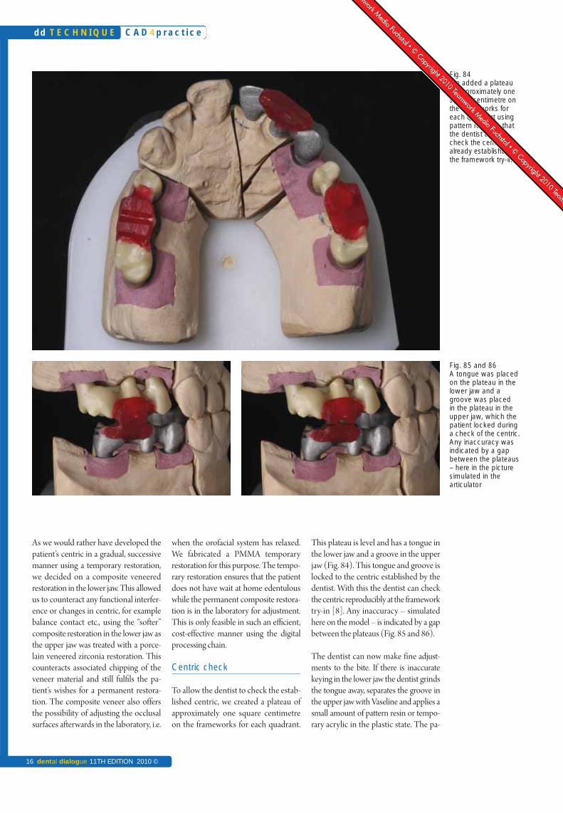
This plateau is level and has a tongue inthe lower jaw and a groove in the upperjaw (Fig. 84). This tongue and groove islocked to the centric established by thedentist. With this the dentist can checkthe centric reproducibly at the frameworktry-in [8]. Any inaccuracy – simulatedhere on the model – is indicated by a gapbetween the plateaus (Fig. 85 and 86).
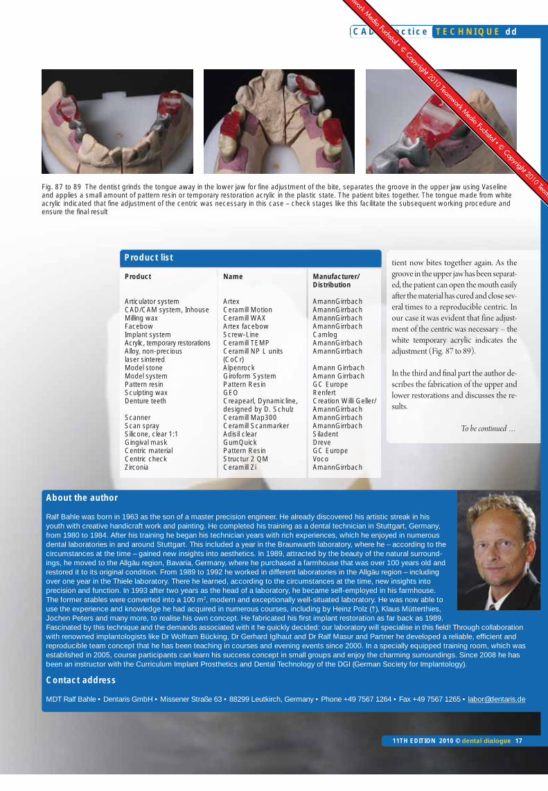
The dentist can now make fine adjust-ments to the bite. If there is inaccuratekeying in the lower jaw the dentist grindsthe tongue away, separates the groove inthe upper jaw with Vaseline and applies asmall amount of pattern resin or tempo-rary acrylic in the plastic state. The pa-
when the orofacial system has relaxed.We fabricated a PMMA temporaryrestoration for this purpose. The tempo-rary restoration ensures that the patientdoes not have wait at home edentulouswhile the permanent composite restora-tion is in the laboratory for adjustment.This is only feasible in such an efficient,cost-effective manner using the digitalprocessing chain.
Centric check
To allow the dentist to check the estab-lished centric, we created a plateau ofapproximately one square centimetreon the frameworks for each quadrant.
As we would rather have developed thepatient’s centric in a gradual, successivemanner using a temporary restoration,we decided on a composite veneeredrestoration in the lower jaw. This allowedus to counteract any functional interfer-ence or changes in centric, for examplebalance contact etc., using the “softer”composite restoration in the lower jaw asthe upper jaw was treated with a porce-lain veneered zirconia restoration. Thiscounteracts associated chipping of theveneer material and still fulfils the pa-tient’s wishes for a permanent restora-tion. The composite veneer also offersthe possibility of adjusting the occlusalsurfaces afterwards in the laboratory, i.e.
Fig. 84 We added a plateauof approximately onesquare centimetre onthe frameworks foreach quadrant usingpattern resin, so thatthe dentist couldcheck the centric already established atthe framework try-in
Fig. 85 and 86 A tongue was placedon the plateau in thelower jaw and agroove was placed in the plateau in the upper jaw, which thepatient locked duringa check of the centric.Any inaccuracy wasindicated by a gapbetween the plateaus– here in the picturesimulated in the articulator
C A D 4 p r a c t i c e T E C H N I Q U E dd
tient now bites together again. As thegroove in the upper jaw has been separat-ed, the patient can open the mouth easilyafter the material has cured and close sev-eral times to a reproducible centric. Inour case it was evident that fine adjust-ment of the centric was necessary – thewhite temporary acrylic indicates theadjustment (Fig. 87 to 89).
In the third and final part the author de-scribes the fabrication of the upper andlower restorations and discusses the re-sults.
To be continued …
About the author
Ralf Bahle was born in 1963 as the son of a master precision engineer. He already discovered his artistic streak in hisyouth with creative handicraft work and painting. He completed his training as a dental technician in Stuttgart, Germany,from 1980 to 1984. After his training he began his technician years with rich experiences, which he enjoyed in numerousdental laboratories in and around Stuttgart. This included a year in the Braunwarth laboratory, where he – according to thecircumstances at the time – gained new insights into aesthetics. In 1989, attracted by the beauty of the natural surround-ings, he moved to the Allgäu region, Bavaria, Germany, where he purchased a farmhouse that was over 100 years old andrestored it to its original condition. From 1989 to 1992 he worked in different laboratories in the Allgäu region – includingover one year in the Thiele laboratory. There he learned, according to the circumstances at the time, new insights into precision and function. In 1993 after two years as the head of a laboratory, he became self-employed in his farmhouse.The former stables were converted into a 100 m2, modern and exceptionally well-situated laboratory. He was now able touse the experience and knowledge he had acquired in numerous courses, including by Heinz Polz (†), Klaus Mütterthies,Jochen Peters and many more, to realise his own concept. He fabricated his first implant restoration as far back as 1989.Fascinated by this technique and the demands associated with it he quickly decided: our laboratory will specialise in this field! Through collaborationwith renowned implantologists like Dr Wolfram Bücking, Dr Gerhard Iglhaut and Dr Ralf Masur and Partner he developed a reliable, efficient andreproducible team concept that he has been teaching in courses and evening events since 2000. In a specially equipped training room, which wasestablished in 2005, course participants can learn his success concept in small groups and enjoy the charming surroundings. Since 2008 he hasbeen an instructor with the Curriculum Implant Prosthetics and Dental Technology of the DGI (German Society for Implantology).
Contact address
MDT Ralf Bahle • Dentaris GmbH • Missener Straße 63 • 88299 Leutkirch, Germany • Phone +49 7567 1264 • Fax +49 7567 1265 • [email protected]
Product
Articulator system CAD/CAM system, Inhouse Milling waxFacebowImplant system Acrylic, temporary restorationsAlloy, non-precious laser sinteredModel stoneModel system Pattern resin Sculpting waxDenture teeth
ScannerScan spray Silicone, clear 1:1Gingival mask Centric material Centric checkZirconia
Name
ArtexCeramill MotionCeramill WAXArtex facebow Screw-Line Ceramill TEMPCeramill NP L units (CoCr)AlpenrockGiroform SystemPattern ResinGEOCreapearl, Dynamicline, designed by D. Schulz Ceramill Map300Ceramill ScanmarkerAdisil clearGumQuickPattern ResinStructur 2 QMCeramill Zi
Manufacturer/Distribution
AmannGirrbachAmannGirrbachAmannGirrbachAmannGirrbachCamlogAmannGirrbachAmannGirrbach
Amann GirrbachAmann GirrbachGC EuropeRenfertCreation Willi Geller/AmannGirrbachAmannGirrbachAmannGirrbachSiladentDreveGC EuropeVocoAmannGirrbach
Product list
Fig. 87 to 89 The dentist grinds the tongue away in the lower jaw for fine adjustment of the bite, separates the groove in the upper jaw using Vaselineand applies a small amount of pattern resin or temporary restoration acrylic in the plastic state. The patient bites together. The tongue made from whiteacrylic indicated that fine adjustment of the centric was necessary in this case – check stages like this facilitate the subsequent working procedure andensure the final result
11TH EDITION 2010 © dental dialogue 17
Review
As extensive full-mouth rehabilitations,as described in this series of articles, arepart of the day-to-day business of the au-thor, he is very happy that with CAD/CAM technology he has access to apractical, efficient tool that can be easilyintegrated into his existing laboratoryconcept. The restoration was initially pre-pared in wax and fixed to the correct posi-tion in the articulator. The wax proto-types were then digitised in the systemscanner and further pro cessed digitallyfrom this point onwards (cf. Part 2). Inpractical terms this meant that all thestructures could now be prepared virtu-ally with the aid of the software. The re-sult: anatomically supporting ZrO2 andnon-precious metal frameworks for thepermanent restoration, fully anatomicalPMMA bridges for the temporaryrestoration stage and anatomical waxfacings for the overpress technique. Allrestorations, the temporary and perma-
nent restorations, were based on the wax-up prepared specifically for the patient.The CAD/CAM technique is there-fore both a highly efficient and reliableprocess. Unnecessary and error-pronemanual copying is no longer required.Thanks to CAD/CAM technology themotto is now: waxed up only once andthen always copied one to one – and inthe material combination of choice.
The traditional procedure, however, is al-so used in this case. This means that itmust now be possible to transfer thestructures, in particular their outer, func-tional section, to the framework accord-ing to the bite registration; at least duringthe customised composite build-up. Thearticulator is virtually the coordinationcentre that must meet the requirementsfor all types of restoration – whethertemporary or permanent. How this issuccessfully achieved has already beendescribed in detail in the other series ofarticles [1, 2]. The silicone index is again
used to transfer of the outer wall of theframework.
From wax prototype to composite
As already described for the mandible,we also fabricated a transparent siliconeindex of the temporary bridge wax-up forthe maxilla in the articulator, (Fig. 90).First a temporary anterior bridge fromtooth 21 to 23 was to be fabricated in themaxilla, as described in Part 1. We insert-ed several openings at convenient posi-tions in the index using twist drills(Fig. 91) into which we were to syringeflowable composite material at a laterstage. We then applied opaque dentine tothe bridge in the pontic and cervical re-gions and tapered it thinly towards theincisal (Fig. 92).
In accordance with the information ac-quired when taking the shade, a thin lay-er of B4 was then applied to the cervical
C A D 4 p r a c t i c e
18 dental dialogue 11TH EDITION 2010 ©
dd T E C H N I Q U E
Change,the constantof the futureIn the final part of his series of articles Master Dental Technician Ralf Bahle demonstrates how convention-al, manually based dental technology is ideally and seamlessly linked to CAD/CAM technical procedures.After the model situation and wax-up had been digitised, the frameworks and superstructures were de-signed with the aid of a computer. The data sets created in this way were then fabricated using CAM. Inthis article the author describes how these frameworks are refined technically. As all frameworks – regard-less of the material from which they were fabricated – are based on the same data set, it is a very efficientworking procedure. Dental technicians can therefore concentrate on what they do best: the functional andaesthetic restoration of missing
An article by Master Dental Technician Ralf Bahle, Leutkirch/Germany
CAD/CAM fabrication of implant-supported bridges in the maxilla and mandible – Part 3
Übersicht
5/10 Part 16/10 Part 27/10 Part 3
Indices
• CAD/CAM• Implant prosthetics• Framework design• Function• Matching• Multiple scan• Silicone index• Transfer die• Wax-up• Zirconia
Category
System-relatedSeries of articles
dental-online-community.comVideo report of this contributor at:
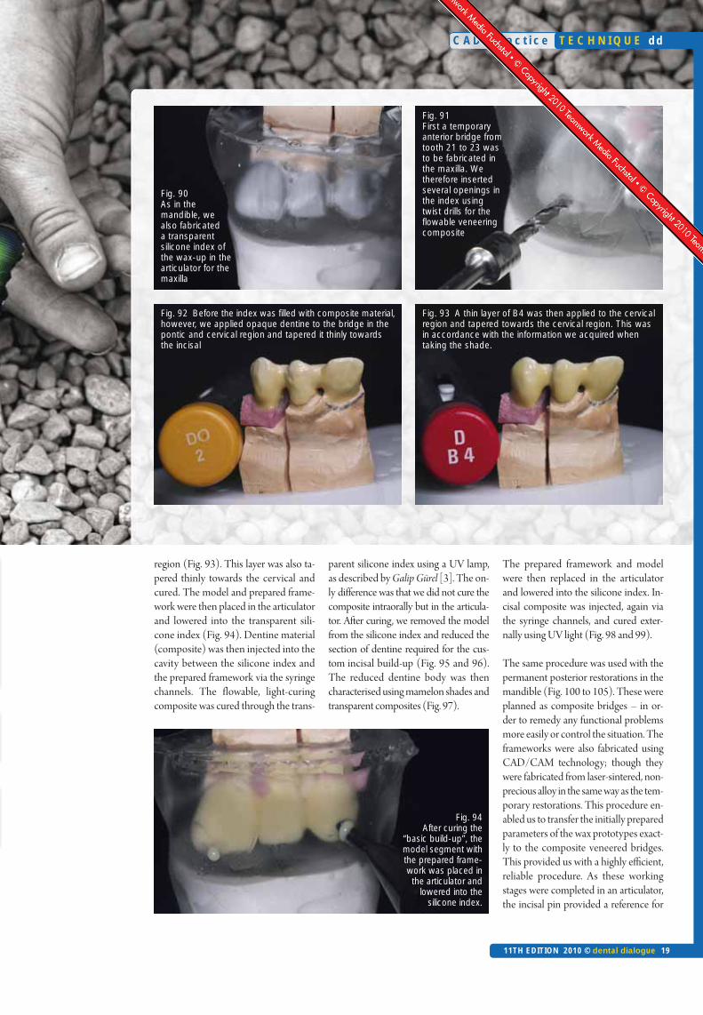
region (Fig. 93). This layer was also ta-pered thinly towards the cervical andcured. The model and prepared frame-work were then placed in the articulatorand lowered into the transparent sili-cone index (Fig. 94). Dentine material(composite) was then injected into thecavity between the silicone index andthe prepared framework via the syringechannels. The flowable, light-curingcomposite was cured through the trans-
parent silicone index using a UV lamp,as described by Galip Gürel [3]. The on-ly difference was that we did not cure thecomposite intraorally but in the articula-tor. After curing, we removed the modelfrom the silicone index and reduced thesection of dentine required for the cus-tom incisal build-up (Fig. 95 and 96).The reduced dentine body was thencharacterised using mamelon shades andtransparent composites (Fig. 97).
The prepared framework and modelwere then replaced in the articulatorand lowered into the silicone index. In-cisal composite was injected, again viathe syringe channels, and cured exter-nally using UV light (Fig. 98 and 99).
The same procedure was used with thepermanent posterior restorations in themandible (Fig. 100 to 105). These wereplanned as composite bridges – in or-der to remedy any functional problemsmore easily or control the situation. Theframeworks were also fabricated usingCAD/CAM technology; though theywere fabricated from laser-sintered, non-precious alloy in the same way as the tem-porary restorations. This procedure en-abled us to transfer the initially preparedparameters of the wax prototypes exact-ly to the composite veneered bridges.This provided us with a highly efficient,reliable procedure. As these workingstages were completed in an articulator,the incisal pin provided a reference for
C A D 4 p r a c t i c e
11TH EDITION 2010 © dental dialogue 19
T E C H N I Q U E dd
Fig. 90 As in themandible, wealso fabricateda transparentsilicone index ofthe wax-up in thearticulator for themaxilla
Fig. 91 First a temporaryanterior bridge fromtooth 21 to 23 wasto be fabricated inthe maxilla. Wetherefore insertedseveral openings inthe index usingtwist drills for theflowable veneeringcomposite
Fig. 92 Before the index was filled with composite material,however, we applied opaque dentine to the bridge in thepontic and cervical region and tapered it thinly towardsthe incisal
Fig. 93 A thin layer of B4 was then applied to the cervicalregion and tapered towards the cervical region. This wasin accordance with the information we acquired when taking the shade.
Fig. 94 After curing the
“basic build-up”, themodel segment withthe prepared frame-work was placed inthe articulator and
lowered into the silicone index.
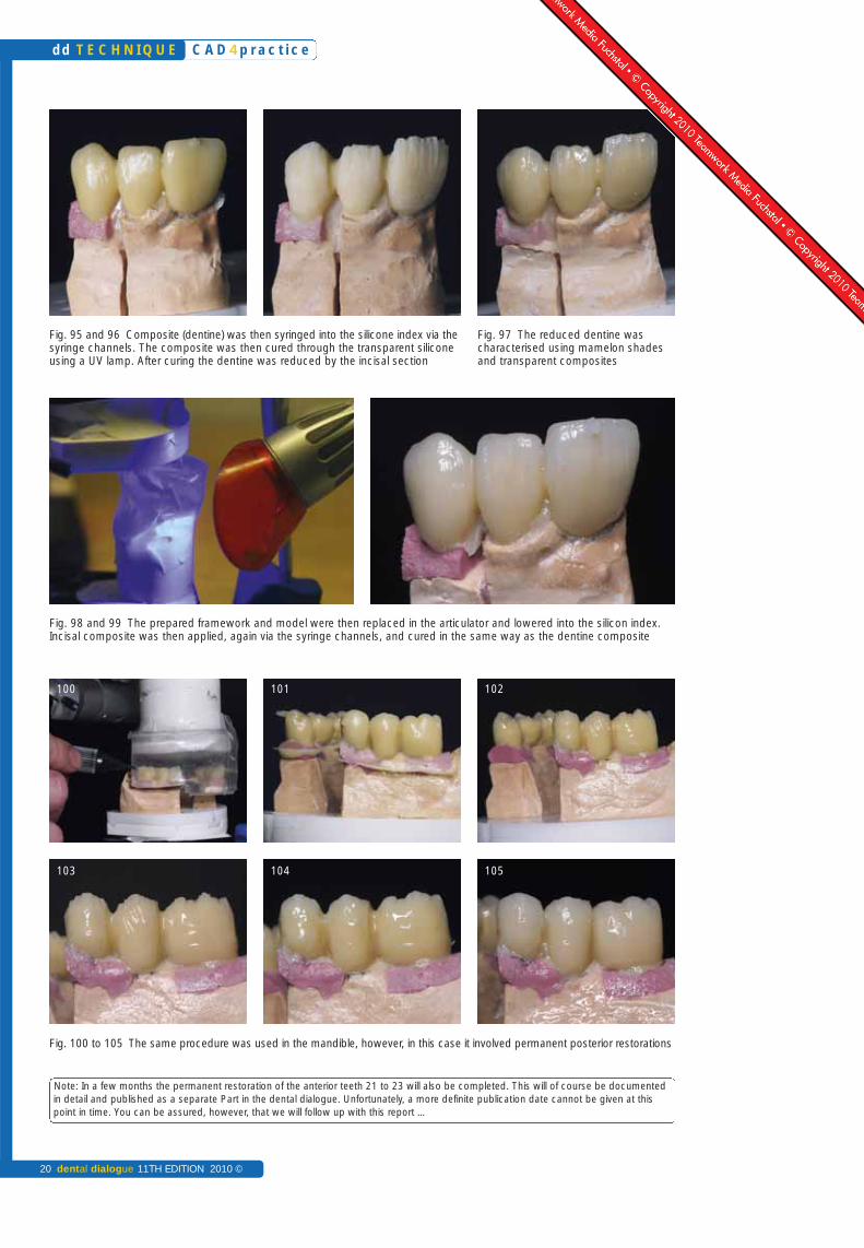
Fig. 95 and 96 Composite (dentine) was then syringed into the silicone index via thesyringe channels. The composite was then cured through the transparent siliconeusing a UV lamp. After curing the dentine was reduced by the incisal section
Fig. 97 The reduced dentine was characterised using mamelon shadesand transparent composites
Fig. 98 and 99 The prepared framework and model were then replaced in the articulator and lowered into the silicon index.Incisal composite was then applied, again via the syringe channels, and cured in the same way as the dentine composite
Fig. 100 to 105 The same procedure was used in the mandible, however, in this case it involved permanent posterior restorations
C A D 4 p r a c t i c e
20 dental dialogue 11TH EDITION 2010 ©
dd T E C H N I Q U E
100 101 102
103 104 105
Note: In a few months the permanent restoration of the anterior teeth 21 to 23 will also be completed. This will of course be documentedin detail and published as a separate Part in the dental dialogue. Unfortunately, a more definite publication date cannot be given at thispoint in time. You can be assured, however, that we will follow up with this report …
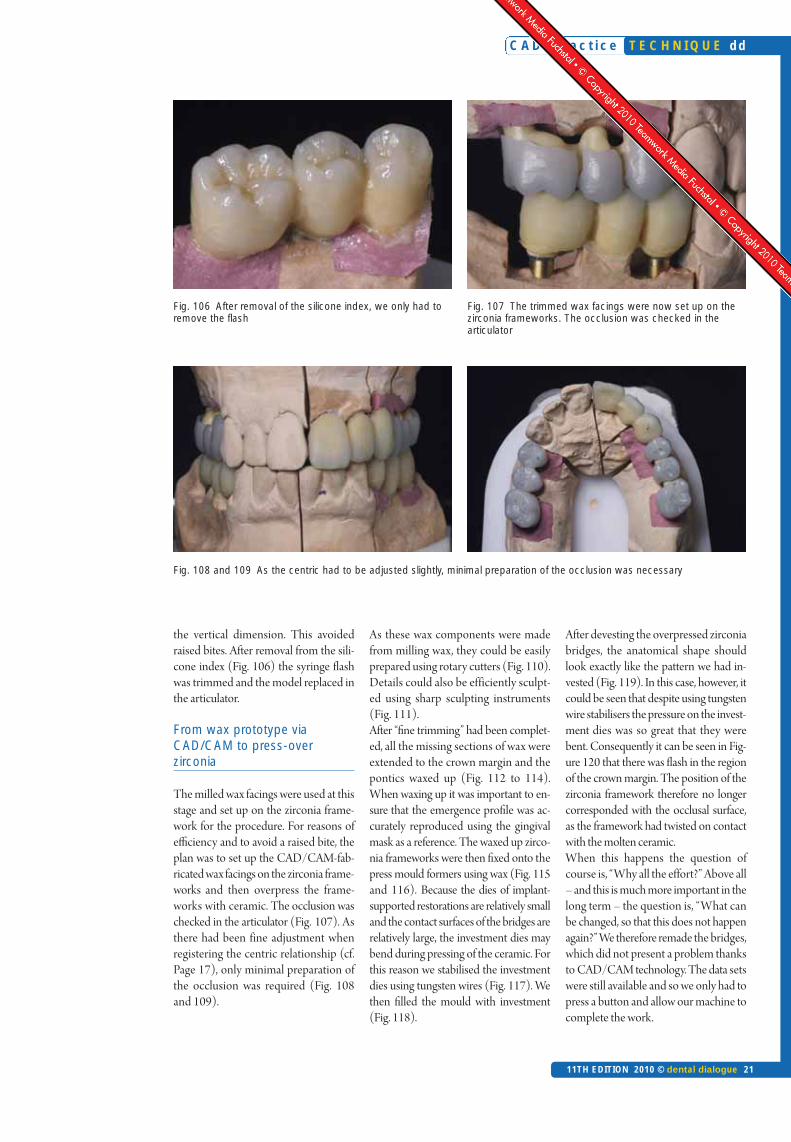
Fig. 106 After removal of the silicone index, we only had toremove the flash
Fig. 107 The trimmed wax facings were now set up on thezirconia frameworks. The occlusion was checked in the articulator
Fig. 108 and 109 As the centric had to be adjusted slightly, minimal preparation of the occlusion was necessary
the vertical dimension. This avoidedraised bites. After removal from the sili-cone index (Fig. 106) the syringe flashwas trimmed and the model replaced inthe articulator.
From wax prototype viaCAD/CAM to press-over zirconia
The milled wax facings were used at thisstage and set up on the zirconia frame-work for the procedure. For reasons ofefficiency and to avoid a raised bite, theplan was to set up the CAD/CAM-fab-ricated wax facings on the zirconia frame-works and then overpress the frame-works with ceramic. The occlusion waschecked in the articulator (Fig. 107). Asthere had been fine adjustment whenregistering the centric relationship (cf.Page 17), only minimal preparation ofthe occlusion was required (Fig. 108and 109).
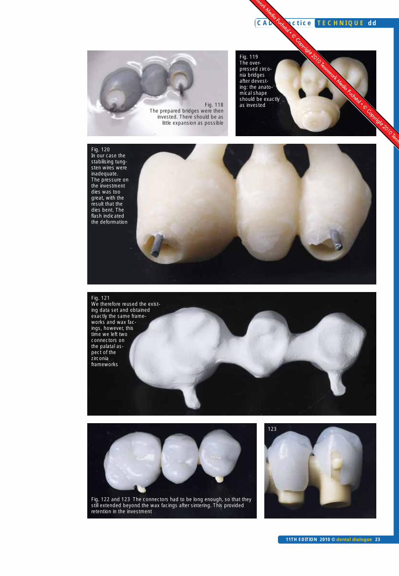
As these wax components were madefrom milling wax, they could be easilyprepared using rotary cutters (Fig. 110).Details could also be efficiently sculpt-ed using sharp sculpting instruments(Fig. 111).After “fine trimming” had been complet-ed, all the missing sections of wax wereextended to the crown margin and thepontics waxed up (Fig. 112 to 114).When waxing up it was important to en-sure that the emergence profile was ac-curately reproduced using the gingivalmask as a reference. The waxed up zirco-nia frameworks were then fixed onto thepress mould formers using wax (Fig. 115and 116). Because the dies of implant-supported restorations are relatively smalland the contact surfaces of the bridges arerelatively large, the investment dies maybend during pressing of the ceramic. Forthis reason we stabilised the investmentdies using tungsten wires (Fig. 117). Wethen filled the mould with investment(Fig. 118).
After devesting the overpressed zirconiabridges, the anatomical shape shouldlook exactly like the pattern we had in-vested (Fig. 119). In this case, however, itcould be seen that despite using tungstenwire stabilisers the pressure on the invest-ment dies was so great that they werebent. Consequently it can be seen in Fig-ure 120 that there was flash in the regionof the crown margin. The position of thezirconia framework therefore no longercorresponded with the occlusal surface,as the framework had twisted on contactwith the molten ceramic.When this happens the question ofcourse is, “Why all the effort?” Above all– and this is much more important in thelong term – the question is, “What canbe changed, so that this does not happenagain?” We therefore remade the bridges,which did not present a problem thanksto CAD/CAM technology. The data setswere still available and so we only had topress a button and allow our machine tocomplete the work.
C A D 4 p r a c t i c e
11TH EDITION 2010 © dental dialogue 21
T E C H N I Q U E dd

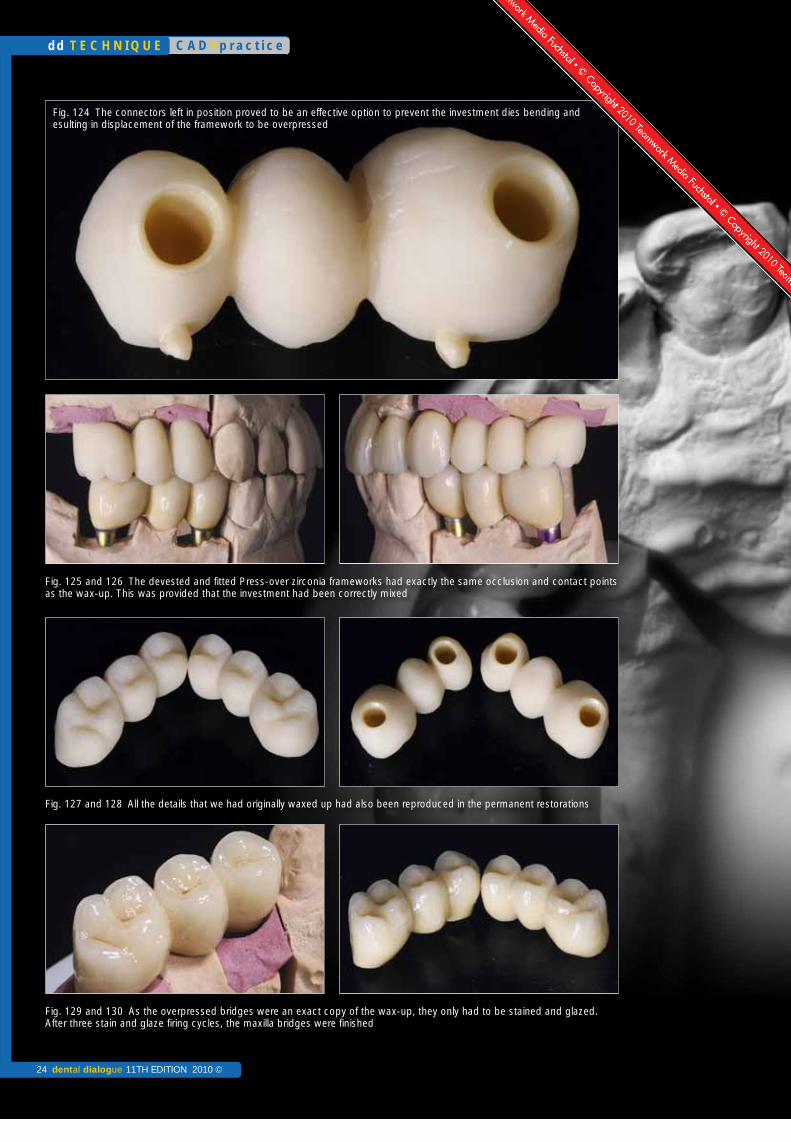
This time we left two connectors on thepalatal aspect of the milled zirconiaframeworks (Fig. 121) that were used forretaining the frameworks in the invest-ment – this is practical trouble shooting.
These connectors had to be long enoughso that they extended beyond the waxfacings after sintering. This provided re-tention in the investment (Fig. 122 and123). This approach proved to be an ef-fective option to prevent the investmentdies from bending and consequently dis-placing the framework (Fig. 124).After devesting and fitting of the over-pressed zirconia frameworks, the occlu-
sion and contact points were just as ac-curate as we had invested them. This wasprovided, however, that the investmenthad been mixed so that there was virtu-ally no expansion (Fig. 125 and 126).
All the details that we had originallywaxed up were to be found in the ve-neered zirconia bridges. Even the di-mensions of the pontics and emergenceprofile had bee accurately transferred(Fig. 127 and 128).
As a result the bridges only had to bestained and glazed. After three stain/glaze firing cycles, the maxillary bridges
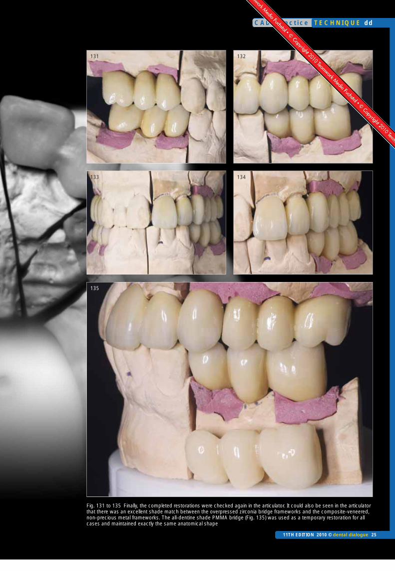
were finished (Fig. 129 and 130). Final-ly, the completed restorations were againchecked in the articulator. It could also beseen in the articulator that there was anexcellent shade match between the over-pressed zirconia bridge framework andthe composite-veneered, non-preciousmetal frameworks (Fig. 131 to 135).
In situ
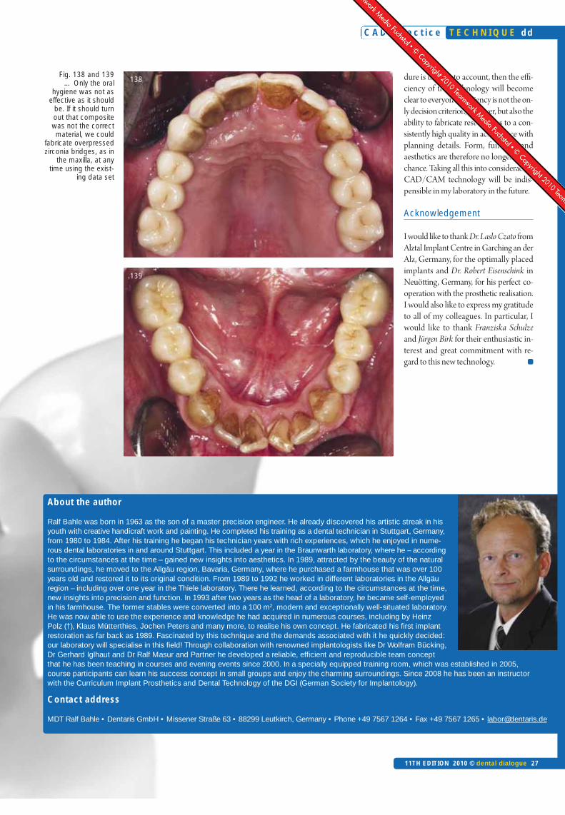
The clinical photographs, taken fourweeks after fitting (Fig. 136 to 139),showed a very smoothly contoured emer-gence profile. The design of the ponticsmade them indistinguishable.
C A D 4 p r a c t i c e
22 dental dialogue 11TH EDITION 2010 ©
dd T E C H N I Q U E
Fig. 110 As milling wax was used, the facings could be easilyprepared using rotary cutters
Fig. 111 Sharp sculpting instruments are also very suitable.The hard wax could be easily sculpted
Fig. 112 to 114 After “fine trimming” the missing wax sections were extended to the crown margins and the pontics waxed up
Fig. 115 and 116 It was important to ensure that the emergence profile was accu-rately reproduced using the gingival mask as a reference. The waxed up zirconiaframeworks were then fixed onto the press mould formers using wax
Fig. 117 We used tungsten wires tostabilise the bridge frameworks
C A D 4 p r a c t i c e
11TH EDITION 2010 © dental dialogue 23
T E C H N I Q U E dd
Fig. 121 We therefore reused the exist-ing data set and obtained exactly the same frame-works and wax fac-ings, however, thistime we left twoconnectors onthe palatal as-pect of thezirconiaframeworks
Fig. 122 and 123 The connectors had to be long enough, so that theystill extended beyond the wax facings after sintering. This provided retention in the investment
123
Fig. 119 The over-pressed zirco-nia bridges after devest-ing: the anato -mical shapeshould be exactlyas investedFig. 118
The prepared bridges were theninvested. There should be as
little expansion as possible
Fig. 120 In our case thestabilising tung-sten wires wereinadequate. The pressure onthe investmentdies was toogreat, with the result that the dies bent. Theflash indicated the deformation
C A D 4 p r a c t i c e
24 dental dialogue 11TH EDITION 2010 ©
dd T E C H N I Q U E
Fig. 125 and 126 The devested and fitted Press-over zirconia frameworks had exactly the same occlusion and contact pointsas the wax-up. This was provided that the investment had been correctly mixed
Fig. 127 and 128 All the details that we had originally waxed up had also been reproduced in the permanent restorations
Fig. 129 and 130 As the overpressed bridges were an exact copy of the wax-up, they only had to be stained and glazed.After three stain and glaze firing cycles, the maxilla bridges were finished
Fig. 124 The connectors left in position proved to be an effective option to prevent the investment dies bending and esulting in displacement of the framework to be overpressed
C A D 4 p r a c t i c e
11TH EDITION 2010 © dental dialogue 25
T E C H N I Q U E dd
Fig. 131 to 135 Finally, the completed restorations were checked again in the articulator. It could also be seen in the articulatorthat there was an excellent shade match between the overpressed zirconia bridge frameworks and the composite-veneered,non-precious metal frameworks. The all-dentine shade PMMA bridge (Fig. 135) was used as a temporary restoration for allcases and maintained exactly the same anatomical shape
131 132
133 134
135
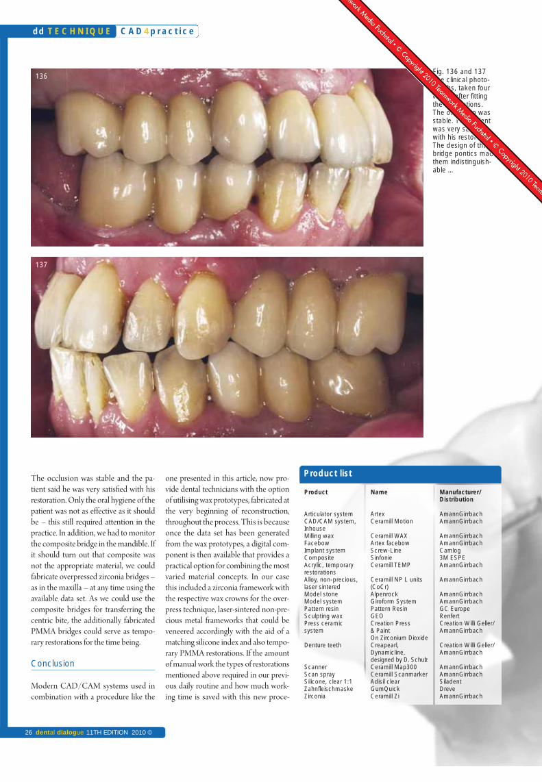
The occlusion was stable and the pa-tient said he was very satisfied with hisrestoration. Only the oral hygiene of thepatient was not as effective as it shouldbe – this still required attention in thepractice. In addition, we had to monitorthe composite bridge in the mandible. Ifit should turn out that composite wasnot the appropriate material, we couldfabricate overpressed zirconia bridges –as in the maxilla – at any time using theavailable data set. As we could use thecomposite bridges for transferring thecentric bite, the additionally fabricatedPMMA bridges could serve as tempo-rary restorations for the time being.
Conclusion
Modern CAD/CAM systems used incombination with a procedure like the
one presented in this article, now pro-vide dental technicians with the optionof utilising wax prototypes, fabricated atthe very beginning of reconstruction,throughout the process. This is becauseonce the data set has been generatedfrom the wax prototypes, a digital com-ponent is then available that provides apractical option for combining the mostvaried material concepts. In our casethis included a zirconia framework withthe respective wax crowns for the over-press technique, laser-sintered non-pre-cious metal frameworks that could beveneered accordingly with the aid of amatching silicone index and also tempo-rary PMMA restorations. If the amountof manual work the types of restorationsmentioned above required in our previ-ous daily routine and how much work-ing time is saved with this new proce-
Product
Articulator system CAD/CAM system,Inhouse Milling waxFacebowImplant system CompositeAcrylic, temporaryrestorationsAlloy, non-precious, laser sinteredModel stoneModel system Pattern resinSculpting waxPress ceramic system
Denture teeth
ScannerScan spraySilicone, clear 1:1ZahnfleischmaskeZirconia
Name
ArtexCeramill Motion
Ceramill WAXArtex facebow Screw-LineSinfonieCeramill TEMP
Ceramill NP L units (CoCr)AlpenrockGiroform SystemPattern ResinGEOCreation Press & PaintOn Zirconium DioxideCreapearl, Dynamicline,designed by D. SchulzCeramill Map300Ceramill ScanmarkerAdisil clearGumQuickCeramill Zi
Manufacturer/Distribution
AmannGirrbachAmannGirrbach
AmannGirrbachAmannGirrbachCamlog3M ESPEAmannGirrbach
AmannGirrbach
AmannGirrbachAmannGirrbachGC EuropeRenfertCreation Willi Geller/AmannGirrbach
Creation Willi Geller/AmannGirrbach
AmannGirrbachAmannGirrbachSiladentDreveAmannGirrbach
Product list
Fig. 136 and 137 The clinical photo-graphs, taken fourweeks after fitting the restorations. The occlusion wasstable. The patientwas very satisfiedwith his restoration.The design of thebridge pontics madethem indistinguish-able …
136
137
C A D 4 p r a c t i c e
26 dental dialogue 11TH EDITION 2010 ©
dd T E C H N I Q U E
About the author
Ralf Bahle was born in 1963 as the son of a master precision engineer. He already discovered his artistic streak in hisyouth with creative handicraft work and painting. He completed his training as a dental technician in Stuttgart, Germany,from 1980 to 1984. After his training he began his technician years with rich experiences, which he enjoyed in nume-rous dental laboratories in and around Stuttgart. This included a year in the Braunwarth laboratory, where he – accordingto the circumstances at the time – gained new insights into aesthetics. In 1989, attracted by the beauty of the naturalsurroundings, he moved to the Allgäu region, Bavaria, Germany, where he purchased a farmhouse that was over 100years old and restored it to its original condition. From 1989 to 1992 he worked in different laboratories in the Allgäuregion – including over one year in the Thiele laboratory. There he learned, according to the circumstances at the time,new insights into precision and function. In 1993 after two years as the head of a laboratory, he became self-employedin his farmhouse. The former stables were converted into a 100 m2, modern and exceptionally well-situated laboratory.He was now able to use the experience and knowledge he had acquired in numerous courses, including by HeinzPolz (†), Klaus Mütterthies, Jochen Peters and many more, to realise his own concept. He fabricated his first implantrestoration as far back as 1989. Fascinated by this technique and the demands associated with it he quickly decided:our laboratory will specialise in this field! Through collaboration with renowned implantologists like Dr Wolfram Bücking,Dr Gerhard Iglhaut and Dr Ralf Masur and Partner he developed a reliable, efficient and reproducible team conceptthat he has been teaching in courses and evening events since 2000. In a specially equipped training room, which was established in 2005,course participants can learn his success concept in small groups and enjoy the charming surroundings. Since 2008 he has been an instructorwith the Curriculum Implant Prosthetics and Dental Technology of the DGI (German Society for Implantology).
Contact address
MDT Ralf Bahle • Dentaris GmbH • Missener Straße 63 • 88299 Leutkirch, Germany • Phone +49 7567 1264 • Fax +49 7567 1265 • [email protected]
Fig. 138 and 139… Only the oral
hygiene was not aseffective as it should
be. If it should turnout that compositewas not the correctmaterial, we could
fabricate overpressedzirconia bridges, as in
the maxilla, at anytime using the exist-
ing data set
138
139
dure is taken into account, then the effi-ciency of this technology will becomeclear to everyone. Efficiency is not the on-ly decision criterion, however, but also theability to fabricate restorations to a con-sistently high quality in accordance withplanning details. Form, function andaesthetics are therefore no longer left tochance. Taking all this into consideration,CAD/CAM technology will be indis-pensible in my laboratory in the future.
Acknowledgement
I would like to thank Dr. Laslo Czato fromAlztal Implant Centre in Garching an derAlz, Germany, for the optimally placedimplants and Dr. Robert Eisenschink inNeuötting, Germany, for his perfect co-operation with the prosthetic realisation.I would also like to express my gratitudeto all of my colleagues. In particular, Iwould like to thank Fran ziska Schulzeand Jürgen Birk for their enthusiastic in-terest and great commitment with re-gard to this new technology.
C A D 4 p r a c t i c e
11TH EDITION 2010 © dental dialogue 27
T E C H N I Q U E dd
NEW
Upgrade available now:
> Ceramill Artex® (virtual articulator)
> Ceramill M-Plant abutment tool
d-lab24.com