Community Based Mappings for the Semantic Web: MappingsTool
85
U NIVERSITAT P OLIT ` ECNICA DE V AL ` ENCIA F INAL P ROJECT Community Based Mappings for the Semantic Web: MappingsTool Author: Omar Pera Mira Computer Science Engineer Escola T` ecnica Superior d’Enginyeria Inform ` atica Supervisor: Antonio Molina DSIC March, 2011
Transcript of Community Based Mappings for the Semantic Web: MappingsTool

UNIVERSITAT POLITECNICA DE VALENCIA
FINAL PROJECT
Community Based Mappings for theSemantic Web: MappingsTool
Author:Omar Pera MiraComputer Science EngineerEscola Tecnica Superior d’Enginyeria Informatica
Supervisor:Antonio MolinaDSIC
March, 2011
Abstract
An extension of BioPortal, an open source ontology repository developedby the UNIVERSITY OF STANFORD, that facilitates the manipulation of map-pings between ontologies. We provide a flexible web user interface thatfacilitate the workflow to create a mapping and the exploration of the rela-tions between ontologies.

Contents
Abstract i
1 Introduction 1
1.1 Presentation . . . . . . . . . . . . . . . . . . . . . . . . . . . . 1
1.2 Overview . . . . . . . . . . . . . . . . . . . . . . . . . . . . . . 1
1.3 Objectives . . . . . . . . . . . . . . . . . . . . . . . . . . . . . 2
1.4 Motivation . . . . . . . . . . . . . . . . . . . . . . . . . . . . . 3
2 Background 4
2.1 Semantic Web . . . . . . . . . . . . . . . . . . . . . . . . . . . 4
2.1.1 What is an ontology . . . . . . . . . . . . . . . . . . . 5
2.1.2 Semantic components overview . . . . . . . . . . . . 6
2.1.3 OWL: Web Ontology Library . . . . . . . . . . . . . . 7
2.1.4 Example: BBC World Cup 2010 . . . . . . . . . . . . . 8
2.2 Relationships between ontologies: mappings . . . . . . . . . 9
2.3 Bioportal: an ontology repository . . . . . . . . . . . . . . . . 13
3 Previous work 15
3.1 Existing tools . . . . . . . . . . . . . . . . . . . . . . . . . . . 15
3.1.1 Prompt + CogZ . . . . . . . . . . . . . . . . . . . . . . 15
Contents iii
3.1.2 Mapping view . . . . . . . . . . . . . . . . . . . . . . . 18
3.2 Comparison with Mappingstool . . . . . . . . . . . . . . . . 18
4 Technology overview 20
4.1 Ruby . . . . . . . . . . . . . . . . . . . . . . . . . . . . . . . . 20
4.1.1 Ruby and Rails . . . . . . . . . . . . . . . . . . . . . . 20
4.2 Javascript . . . . . . . . . . . . . . . . . . . . . . . . . . . . . . 21
4.2.1 AJAX . . . . . . . . . . . . . . . . . . . . . . . . . . . . 22
4.2.2 JSON . . . . . . . . . . . . . . . . . . . . . . . . . . . . 23
4.2.3 jQuery . . . . . . . . . . . . . . . . . . . . . . . . . . . 24
4.3 FlexViz: ontology visualization tool . . . . . . . . . . . . . . 25
4.4 Web Services . . . . . . . . . . . . . . . . . . . . . . . . . . . . 27
4.5 Bioportal . . . . . . . . . . . . . . . . . . . . . . . . . . . . . . 27
4.5.1 Bioportal UI . . . . . . . . . . . . . . . . . . . . . . . . 27
4.5.2 Bioportal Core . . . . . . . . . . . . . . . . . . . . . . . 28
5 Software architecture and design 30
5.1 Architecture overview . . . . . . . . . . . . . . . . . . . . . . 30
5.1.1 Client side . . . . . . . . . . . . . . . . . . . . . . . . . 31
5.1.2 Server side . . . . . . . . . . . . . . . . . . . . . . . . . 33
5.2 UI overview . . . . . . . . . . . . . . . . . . . . . . . . . . . . 34
5.2.1 Flexibility . . . . . . . . . . . . . . . . . . . . . . . . . 34
5.2.2 Usability . . . . . . . . . . . . . . . . . . . . . . . . . . 35
5.2.3 Mockups . . . . . . . . . . . . . . . . . . . . . . . . . . 35
Contents iv
6 Main use cases 37
6.1 Browse and search ontology concepts . . . . . . . . . . . . . 37
6.2 Browse mappings . . . . . . . . . . . . . . . . . . . . . . . . . 38
6.3 Information about an ontology concept . . . . . . . . . . . . 40
6.4 Create a mapping . . . . . . . . . . . . . . . . . . . . . . . . . 41
6.5 Discussions about a mapping . . . . . . . . . . . . . . . . . . 42
6.6 Visualize the context of a concept . . . . . . . . . . . . . . . . 43
6.7 Export to RDF the mappings between 2 ontologies . . . . . . 44
7 Conclusions 45
Bibliography 47
A Mockups 48
B RDF Export 53
C Deploying Bioportal Core 57
D Deploying Bioportal UI 68
Chapter 1
Introduction
1.1 Presentation
The aim of this document is the report for the Final Project Community BasedMappings for the Semantic Web: MappingsTool, for the Escola Tecnica Supe-rior d’Enginyeria Informatica (ETSINF) of the Universitat Politecnica deValencia (UPV).
1.2 Overview
The application presented in this document is a mapping editor betweenconcepts of different ontologies. In the context of the Semantic Web, themappings between controlled vocabularies in a given domain are essen-tial to interoperability between different data systems. In other words, it isimportant to have a machine-readable way for a computer to understandhow terms are related (for example, if one term is equivalent to, more gen-eral than, or narrower than another term).
We have developed Mappingstool, an extension of Bioportal1 that eases themanipulation of mappings across ontologies. We formalize the relation-ships between ontology concepts by providing a first approach of a spec-ification for representing the mappings involved, and providing a flexible
1BioPortal is an open source ontology repository developed by the UNIVERSITY OFSTANFORD, more information in the subsection 2.3

Objectives 2
user interface that facilitates the generation of mappings and the explo-ration of the relations. Users can browse the mappings, create new ones,download them, or begin a discussion about the mapping itself.
Each mapping has its own set of metadata that describes who created themapping and when, application context in which the mapping might bevalid, mapping source, the specific mapping relationship, and other prop-erties.
Mappings between ontologies are key to interoperability data in the visionof Semantic Web. They are a fundamental component to achieve the inte-gration and reuse of information. Section 2 will provide some backgroundinformation, and provide some pointers that show the connection points toour work.
This power users of this extension is a small group of domain experts, whoare familiar with the controlled vocabularies. Doing accurate mapping re-quires an in-depth knowledge of the meaning of the terms in each vocabu-lary.
1.3 Objectives
• Develop a tool that facilitates the creation of mappings between on-tologies encouraging collaboration between domain experts.
• Design a flexible web application on top of Bioportal in which youcan see the context of a visual mapping, promoting collaboration anddiscussion among experts and facilitate the exploration of relationsbetween ontologies.
• Encourage the use of mappings between controlled vocabularies toprovide interoperability between different types of systems in a spe-cific domain
• Formalize relationships between ontological vocabulary by creating awell known vocabulary that contains the key relationships as OWL2:same as, owl : inverse o f , etc. In addition to give the possibility toadd new relationship types.
2More detailed information in the Subsection 2.1.3
Motivation 3
1.4 Motivation
Within the context of the project OASIS3 there was a key requeriment tohave an open repository for ontologies and to be able to reuse, create rela-tions between them, collaborate, etc. There are several research and devel-opment initiatives at this time aiming at producing ’open ontology reposi-tories’; the most stable and mature of these is the BioPortal platform devel-oped for the Biomedical domain. This platform has been developed by theNational Center for Biomedical Ontology of the UNIVERSITY OF STANFORD.
We have taken BioPortal and considered the precise extensions and mech-anisms necessary for moving the BioPortal framework to the Assistive Tech-nologies domain. The result is a new repository, ORATE4, that is the firstinstantiation of BioPortal technology outside of the Biomedical domain.ORATE has been implemented by the University of Bremen in the am-bit of Assistive Technologies (with ontologies such as Device, Sensor, Trip,GPS or Transportation) where the relations are key within the context ofthe project.
In typical OASIS scenarios, several services and devices have to be in inter-action and hence the corresponding software must be highly interoperable.As the software is driven by ontologies, these ontologies must be interop-erable or connectable too: if two applications, based on ontologies, inter-operate in a well specified way then their underlying ontologies must berelated in a meaningful way.
Interoperability or connectivity in the case of ontologies means that twoontologies are connected via a relation with a well defined semantics. Inmany cases the purpose of such connections is to transport concepts andtheir implications from the source ontology to the target ontology. A sim-ple example is the import relation where the target ontology imports allknowledge from a source ontology. This interoperability between ontolo-gies has been acquired with Mappingstool, being able to easily formalizerelationships between ontology concepts.
3Open architecture for Accessible Services, it is an European Project with the scope torevolutionise the interoperability, quality, breadth and usability of services for all daily ac-tivities of older people.
4Ontology Repository for Assistive Technologies

Chapter 2
Background
2.1 Semantic Web
The World Wide Web is an information resource with virtually unlimitedpotential. However, this potential is relatively untapped because it is dif-ficult for machines to process and integrate this information meaningfully.The Semantic Web is based on the idea of adding semantic and ontologicalmetadata to the World Wide Web. This extra information - that describesits content, meaning and their relationships - must be provided formally,so that can be evaluated automatically by processing machines.
Researchers have begun to explore the potential of associating web contentwith explicit meaning. Rather than rely on natural language processing toextract this meaning from existing documents, this approach requires au-thors to describe documents using a knowledge representation language.
The main obstacle is the fact that the Web was not designed to be processedby machines. Although, web pages include special information that tells acomputer how to display a particular piece of text or where to go when alink is clicked, they do not provide any information that helps the machineto determine what the text means. Thus, to process a web page intelligently,a computer must understand the text, but natural language understandingis known to be an extremely difficult and unsolved problem.
With the Semantic Web, the software is able to process your content, rea-soning with it, combining and logical deductions for solve everyday prob-lems automatically. All this knowledge is based on ontologies, leading to
Semantic Web 5
an intelligence derived from the possibilities of inference implicit in RDF /OWL - languages used to generate ontologies.
At its core, the semantic web comprises a set of design principles, collab-orative working groups, and a variety of enabling technologies. Some ele-ments of the semantic web are expressed as prospective future possibilitiesthat are yet to be implemented or realized. On the other hand, other el-ements of the semantic web are expressed in formal specifications. Someof these include Resource Description Framework (RDF), a variety of datainterchange formats (e.g. RDF/XML, N3, Turtle, N-Triples), and notationssuch as RDF Schema (RDFS) and the Web Ontology Language (OWL), allof which are intended to provide a formal description of concepts, terms,and relationships within a given knowledge domain.
Tim Berners-Lee, inventor of the Web, has coined the term Semantic Webto describe this approach.
2.1.1 What is an ontology
This definition was originally proposed by Tom Gruber.
In the context of knowledge sharing, I use the term ontology tomean a specification of a conceptualization. That is, an ontol-ogy is a description (like a formal specification of a program) ofthe concepts and relationships that can exist for an agent or acommunity of agents. This definition is consistent with the us-age of ontology as set-of-concept-definitions, but more general.And it is certainly a different sense of the word than its use inphilosophy.
What is important is what an ontology is for. My colleagues andI have been designing ontologies for the purpose of enablingknowledge sharing and reuse. In that context, an ontology isa specification used for making ontological commitments. Theformal definition of ontological commitment is given below. Forpragmetic reasons, we choose to write an ontology as a set ofdefinitions of formal vocabulary. Although this isn’t the onlyway to specify a conceptualization, it has some nice propertiesfor knowledge sharing among AI software (e.g., semantics inde-pendent of reader and context). Practically, an ontological com-mitment is an agreement to use a vocabulary (i.e., ask queries

Semantic Web 6
and make assertions) in a way that is consistent (but not com-plete) with respect to the theory specified by an ontology. Webuild agents that commit to ontologies. We design ontologiesso we can share knowledge with and among these agents.
2.1.2 Semantic components overview
To represent the Semantic Web, the main technologies are:
XML Provides an elemental syntax for content structure within documents,yet associates no semantics with the meaning of the content containedwithin.
URIs A global naming scheme
RDF A standard syntax for describing data. An RDF-based model can berepresented in XML syntax.
RDF Schema A standard means of describing the properties of that data
OWL A standard means of describing relationships between data items.OWL adds more vocabulary for describing properties and classes:among others, relations between classes (e.g. disjointness), cardinal-ity (e.g. ”exactly one”), equality, richer typing of properties, charac-teristics of properties (e.g. symmetry), and enumerated classes.
SPARQL It is a protocol and query language for semantic web data sources.
The intent is to enhance the usability and usefulness of the Web through:
• Structured documents with semantic information, this could be machine-understandable information about the human-understandable con-tent of the document.
• Data systems systems using the RDF and SPARQL standards.
• Ontotologies and maps between vocabularies that allow documentcreators to know how to mark up their documents so that agents canuse the information in the supplied metadata.
• Automated agents to perform tasks and infer information using thesemantic data.
Semantic Web 7
2.1.3 OWL: Web Ontology Library
The ontologies that are used in Mappingstool are of the type OWL, beingable to add relations between classes.
OWL is a W3C specification built upon RDF and RDFS, that defines thetypes of relationships that can be expressed in RDF using an XML vo-cabulary to indicate the hierarchies and relationships between different re-sources. In other words, as we have explained in the previous section, on-tologies define data models in terms of classes, subclasses, and properties.This ontologies are expressed with OWL.
Since taxonomies (systems of classification) express the hierarchical rela-tionships that exist between resources, we can use OWL to assign proper-ties to classes of resources and allow their subclasses to inherit the sameproperties. OWL also utilizes the XML Schema datatypes and supportsclass axioms such as subClassOf, disjointWith, etc., and class descriptionssuch as unionOf, intersectionOf, etc.
The basic components of OWL include:
• Classes are the basic building blocks of an OWL ontology. A class isa concept in a domain. Classes usually constitute a taxonomic hierar-chy (a subclass-superclass hierarchy).
• Properties have two main categories:
• Object properties, which relate individuals to other individuals.
• Datatype properties, which relate individuals to datatype values, suchas integers, floats, and strings.
• Individuals are instances of classes, and properties can relate one in-dividual to another.
We have focus our Mappingstool in establishing relations between classes,not individuals. Bioportal was not supported to retrieve the individualsbut they had it in the roadmap, so the main reason was not to reinvent thewheel.

Semantic Web 8
2.1.4 Example: BBC World Cup 2010
In order to show a real example of the use of Semantic Web technologiesand mappings, we are going to present what was developed by BBC site topublish information from the World Cup 2010.
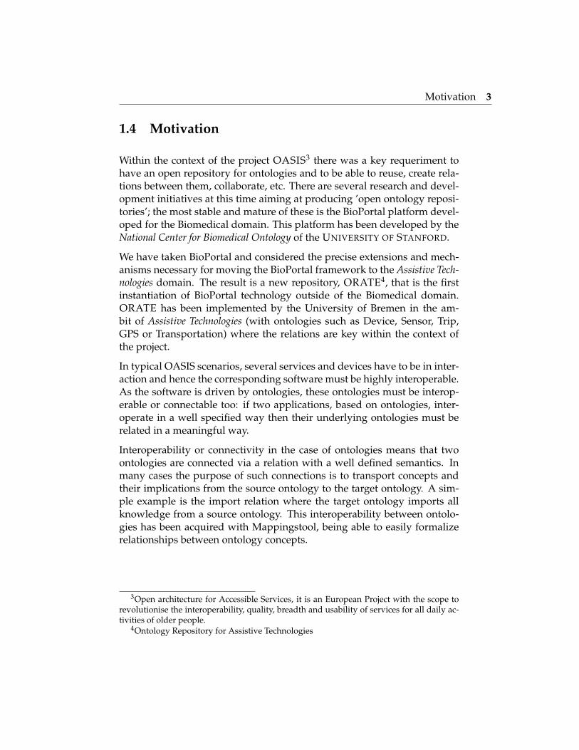
The period of the World Cup event is a perfect example of dynamic data,with lots of relationships between Players, Teams, groups, etc. They cre-ated a framework that facilitated the publication of automated metadata-driven web pages that required minimal journalistic management, as theyautomatically aggregate and render links to relevant stories.
The underlying publishing framework does not author content directly,rather it publishes data about the content (metadata). The published meta-data described the World Cup content, providing rich content relationshipsand semantic navigation. By querying this published metadata they wereable to create dynamic page aggregations for teams, groups and players.
The origin of these dynamic aggregations is a rich set of ontologies. Theontologies described entity existence, groups and relationships between theconcepts that describe the World Cup. For example, ”Frank Lampard” ispart of the ”England Squad” and the ”England Squad” competes in ”GroupC” of the ”FIFA World Cup 2010”.
This diagram gives a high-level overview of the main architectural compo-nents of this domain-driven framework.
The journalists could tag concepts to content, for example associated thecontent of ”Puyol” with the story ”Shark Puyol beats Germany”.
In addition to the manual selective tagging and mapping process, journalist-authored content is automatically analysed against the World Cup ontol-ogy. A natural language and ontological determiner process automaticallyextracts World Cup concepts embedded within a textual representation ofa story.
Journalist-published metadata is captured and made persistent for query-ing using the resource description framework (RDF) metadata representa-tion and triple store technology. A RDF triplestore and SPARQL approachwas chosen over and above traditional relational database technologies dueto the requirements for interpretation of metadata with respect to an onto-logical domain model.
Relationships between ontologies: mappings 9
Figure 2.1: Architectural components of the BBC semantic web system
This is a perfect example about what could be the next phase of Internet,Semantic Web or Web 3.0.
2.2 Relationships between ontologies: mappings
The ability to specify semantic mappings between ontologies is an impor-tant research agenda in the semantic web community. Several approacheshave been proposed for alignment between ontologies ranging from en-tirely manual (the one explained in the document), to semi-automatic, tofully-automatic mapping techniques.
More recently, with the growing number of ontologies and the increasing

Relationships between ontologies: mappings 10
requirement for their alignment, community-based approaches to createmappings have been necessary to that allow users and domain experts tospecify semantic correspondences in a collaborative manner.
In configurations for which different conceptualizations of the same do-main can exist, information systems must respond effectively allowing thecontextualization of it. Coordination and the relationship of concepts (map-ping) help you share, reuse and integrate different controlled vocabularies.
Similarity
We start with a short definition of similarity from a dictionary: having char-acteristics in common, being comparable. From our point of view we wantto compare two entities to find identity among them. We also give a formaldefinition of similarity derived from [3]:
• sim(x, y) ∈ [0..1]
• sim(x, y) = 1⇒ x = y: two objects are identical.
• sim(x, y) = 0: two objects are different and have no common charac-teristics.
• sim(x, x) = 1: similarity is reflexive.
• sim(x, y) = sim(y, x): similarity is symmetric.5
• similarity and distance are inverse to each other.
• sim(x, z) ≤ (sim(x, y) + sim(y, z)): The triangular inequation is validfor the similarity measure.
Similarity for Ontologies
As it is pointed out in [4], What is the meaning of similarity in the context ofontologies? The basic assumption is that knowledge is captured in an arbi-trary ontology encoding. Based on the consistent semantics the coherencesmodelled within the ontology become understandable and interpretable.From this it is possible to derive additional knowledge such as, in our case,

Relationships between ontologies: mappings 11
Figure 2.2: Relations between ontologies
similarity of entities in different ontologies. An example shall clarify howto get from encoded semantics to similarity: by understanding that labelsdescribe entities in natural language one can derive that entities having thesame labels are similar. This is not a rule which always holds true, but itis a strong indicator for similarity. Other constructs as subclass relations ortype definition can be interpreted similarly.
Mapping
Due to the wide range of expressions used in this area (merging, alignment,integration etc.), we want to describe our understanding of the term map-ping. The definition for mapping given by [9] is:
Given two ontologies A and B, mapping one ontology with an-other means that for each concept (node) in ontology A, we try

Relationships between ontologies: mappings 12
to find a corresponding concept (node), which has the same orsimilar semantics, in ontology B and viceverse.
We only consider one-to-one mappings between single entities in Map-pingstool. Neither do we cover mappings of whole ontologies or sub-trees,nor complex mappings or functional transformation of attributes.
Example within OASIS context
We will illustrate the relations by the following example within the OASISproject context: Suppose there is an ontology describing the functionalityof a mobile phone and another ontology describing an application to beplugged in. Then an ontology describing both the mobile phone and itsplug-in is most likely given by importing the plug-in ontology into themobile phone ontology. For instance, if the target ontology of the mo-bile phone has a notion of telephone numbers in the address book and thesource ontology of the plug-in has in addition to this a notion of emergencynumbers as a subclass of telephone numbers, then the target ontology willalso gain a notion of emergency numbers when it imports the source on-tology. An alternative way of describing this is to say that a plug-in is’integrated’ into a target system.
With interoperability we always associate some degree of independencebetween the participating components. Another relevant example: in par-ticular for the elderly it may be annoying to have for each and every remotecontrollable device its own remote control with its own specific style of be-ing handled. Different handling for the same purpose is an unnecessaryirritation. A remote control that can be used to control several different de-vices instead may then be desirable. Typically such a remote control shouldhave only few operating elements with a very intuitive operationafor in-stance: a wheel that can be used to adjust the volume of the radio or of thetelevision or its brightness depending on the context. With such an exam-ple we already see several natural ’modularities’ that call for independenceof accounts. The basic operation and meaning of the ’wheel’ gadget can bedefined independently of the particular values that it is used to manipulate.Those values are themselves then defined within the individual ’theories’of TV operation, radio operation, and so on. Interoperability is achieved bydefining the necessary relation between the modules.
Bioportal: an ontology repository 13
This very simple scenario already suggests the value of adopting differentontological perspectives to describe the involved objects: this wheel can bejust an object that can be turned, it can be a volume controller or a bright-ness controller, or it can be a controller for a radio or a television. Moreover,volume is a position for the wheel as volume controller, but a certain volt-age for the speaker, or decibel for an acoustic sensor, etc.
Concerning modularity we therefore come to at least two conclusions. First,different purposes of a single entity can call for different ontologies reflect-ing those purposes. It is even possible that different perspectives can leadto incompatible ontologies; for instance, what is called a small symbol inan ontology for visually users with a vision deficit might be called a bigsymbol in an ontology for users without such a deficit. In fact, this is onlyone type of the many heterogeneity requirements.
2.3 Bioportal: an ontology repository
Bioportal1 is an open source ontology repository where a user can searchand browse the ontologies, find resources annotated with concepts fromthese ontologies, and download ontologies for their use. Provides facilitiesfor browsing, visualizing, and reusing ontologies as well as a basic reposi-tory for ontology storage and retrieval.
Researchers in biomedical informatics submit their ontologies to BioPortaland others can access the ontologies through the Bioportal user interfaceor through web services. The Bioportal users can browse and search theontologies, update the ontologies in the repository by uploading new ver-sions, comment on any ontology (or portion of an ontology) in the reposi-tory, evaluate it and describe their experience in using the ontology,
Understanding how the concepts in different ontologies relate to one an-other is one of the key requirements of BioPortal users. We refer to therelations between concepts in different ontologies as concept mappings, orsimply mappings.
Mappingstool is one of the additions within the BioPortal framework thatmove the system further towards the OASIS project goals of modularityand re-usability.
1http://bioportal.bioontology.org/

Bioportal: an ontology repository 14
Figure 2.3: ORATE homepage
The Ontology Repository for Assistive Technologies (ORATE) is built uponBioportal technology. We will use Bioportal when we are referering to theORATE version of the Bioportal platform that we have extended.
Chapter 3
Previous work
3.1 Existing tools
A brief overview about the existing tools for ontology mapping is provided.
3.1.1 Prompt + CogZ
PROMPT is a Protege1 plugin that supports various tasks for managingmultiple ontologies, including ontology mapping. The ontology mappingprocess starts by performing an initial comparison of the source and tar-get to be mapped, based on lexical comparison of class names (other algo-rithms are available). After the comparison, you can create mappings froma set of candidates or user-defined mappings. As you are creating the map-pings, Prompt ’monitors’ the correspondences that you create and createsinstances of its built-in mapping ontology behind the scenes
The PROMPT plugin framework allows developers to plug in your ownmapping algorithms for initial comparison of ontologies or your own userinterface. At the moment there are some plugins available in Prompt (theseplugins are installed when you install PROMPT):
CogZ alternative perspective to Prompt’s mapping interface.
1Protege is a free, open source ontology editor and knowledge-base framework. Moreinfo in http://protege.stanford.edu/

Existing tools 16
Figure 3.1: Prompt tab plugin
FOAM in Prompt use the FOAM algorithm for mapping
Synonyms if you have synonyms for your terms, have Prompt use syn-onyms to create lexical mappings
CogZ has been implemented with mapping user support in mind. It sup-ports a variety of filters to aid the mapping process. It also uses a visualrepresentation of mappings rather than a simple list. Finally, it supports avisual graph-based representation of ontology concepts that allow you toinspect the semantics/context of the terms you intend to map.
PROMPT and its CogZ extension are under active development and areincluded in the full installation of Protege. This work environment man-ages multiple ontologies and performs automatic and manual mappings,and it is quite full-featured.
The main features of CogZ are:

Existing tools 17
Figure 3.2: CogZ user interface
• View structural representation of mapping suggestions in Prompt.
• Identifies candidate rich areas of the ontologies.
• Provides progress indicators about the completion of the mapping.
• Visualizes suggested, created, and temporary mappings and visuallysupports manual mapping of terms.
• Provides ontology and mapping filtering.
• Mapping status and hierarchy reports.

Comparison with Mappingstool 18
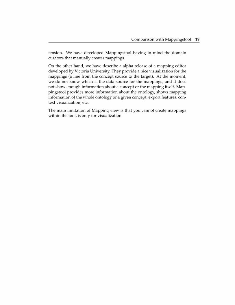
3.1.2 Mapping view
This experimental tool2 is under development by Victoria University andis constrained to the visualization of the relationship, the classes, and thecorresponding class hierarchies. The list of mappings is provided so thatthe users can navigate through the mappings.
Figure 3.3: Mapping view
At the moment there is no way to know the mapping origin at the moment.It is developed in FLEX3.
3.2 Comparison with Mappingstool
Mappingstool provides a service that allow the user to create and manip-ulate mappings online, unlike the plugin Prompt + CogZ that is a desktopapplication. This Protege plugin is extremely powerful providing featuressuch as automatic mapping based on lexic comparison and visual repre-sentation of mappings, but that was not the objective of our Bioportal ex-
2http://keg.cs.uvic.ca/ncbo/mapping/MappingApp.html3Framework for deployment of cross-platform Rich Internet Applications based on the
Adobe Flash, explained in 4.3
Comparison with Mappingstool 19
tension. We have developed Mappingstool having in mind the domaincurators that manually creates mappings.
On the other hand, we have describe a alpha release of a mapping editordeveloped by Victoria University. They provide a nice visualization for themappings (a line from the concept source to the target). At the moment,we do not know which is the data source for the mappings, and it doesnot show enough information about a concept or the mapping itself. Map-pingstool provides more information about the ontology, shows mappinginformation of the whole ontology or a given concept, export features, con-text visualization, etc.
The main limitation of Mapping view is that you cannot create mappingswithin the tool, is only for visualization.

Chapter 4
Technology overview
We will present the technologies that have been used to develop this Bio-portal extension, with references how we have used them.
4.1 Ruby
Ruby is a dynamically typed programming language similar to Python,Smalltalk and Perl. Its creator, Yukihiro ’matz’ Matsumoto, blended partsof his favorite languages (Perl, Smalltalk, Eiffel, Ada, and Lisp) to form anew language that balanced functional programming with imperative pro-gramming. In Ruby, everything is an object. Every bit of information andcode can be given their own properties and actions.
4.1.1 Ruby and Rails
Ruby on Rails1 is an open source web application framework for the Rubyprogramming language. It enables rapid prototyping as well as solid inte-gration with web services.
It is intended to be used with an Agile development methodology that isused by web developers for rapid development. It has became a leadingmature UI framework supported by large software development commu-nities.
1Official website: http://rubyonrails.org/
Javascript 21
There are two basic principles that govern the way that Ruby on Railsworks. The first is often referred to as DRY, or Don’t Repeat Yourself andthe second principle is COC or Convention over Configuration. This frame-work has been growing along the years due to its simplicity and commu-nity.
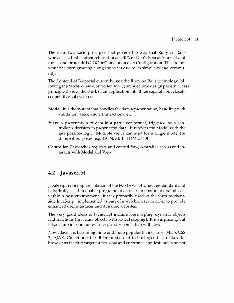
The frontend of Bioportal currently uses the Ruby on Rails technology fol-lowing the Model-View-Controller (MVC) architectural design pattern. Theseprinciple divides the work of an application into three separate but closelycooperative subsystems:
Model It is the system that handles the data representation, handling withvalidation, association, transactions, etc.
View A presentation of data in a particular format, triggered by a con-troller’s decision to present the data. It renders the Model with theless possible logic. Multiple views can exist for a single model fordifferent purposes (e.g. JSON, XML, HTML, PDF).
Controller Dispatches requests and control flow, centralize access and in-teracts with Model and View.
4.2 Javascript
JavaScript is an implementation of the ECMAScript language standard andis typically used to enable programmatic access to computational objectswithin a host environment. It it is primarily used in the form of client-side JavaScript, implemented as part of a web browser in order to provideenhanced user interfaces and dynamic websites.
The very good ideas of Javascript include loose typing, dynamic objectsand functions (first class objects with lexical scoping). It is surprising, butit has more in common with Lisp and Scheme than with Java.
Nowadays it is becoming more and more popular thanks to HTML 5, CSS3, AJAX, Comet and the different stack of technologies that makes thebrowser as the first target for personal and enterprise applications. And not

Javascript 22
Figure 4.1: MVC arquitectural design pattern with RoR framework
only on the client side, there are some interesting projects around server-side Javascript such as Node.js2, a toolkit for writing extremely high per-formance non-blocking event driven network servers in JavaScript.
4.2.1 AJAX
AJAX (Asynchronous JavaScript and XML) is a method of building inter-active applications for the Web that process user requests immediately.Ajax combines several programming tools including JavaScript, dynamicHTML (DHTML), Extensible Markup Language (XML), cascading stylesheets (CSS), the Document Object Model (DOM), and the Microsoft ob-ject, XMLHttpRequest. Ajax allows content on Web pages to update imme-diately when a user performs an action, unlike an HTTP request, duringwhich users must wait for a whole new page to load. XML is not actually
2The author’s definition is ’Evented I/O for V8 JavaScript’, more info in http://nodejs.
org
Javascript 23
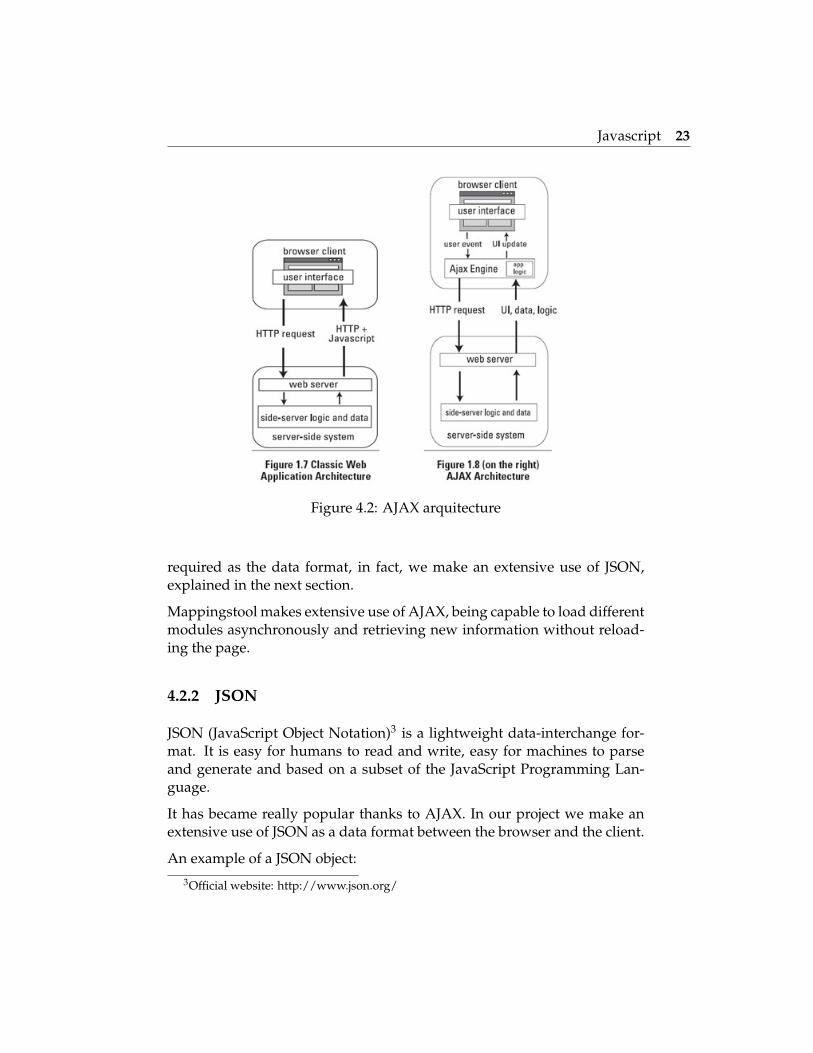
Figure 4.2: AJAX arquitecture
required as the data format, in fact, we make an extensive use of JSON,explained in the next section.
Mappingstool makes extensive use of AJAX, being capable to load differentmodules asynchronously and retrieving new information without reload-ing the page.
4.2.2 JSON
JSON (JavaScript Object Notation)3 is a lightweight data-interchange for-mat. It is easy for humans to read and write, easy for machines to parseand generate and based on a subset of the JavaScript Programming Lan-guage.
It has became really popular thanks to AJAX. In our project we make anextensive use of JSON as a data format between the browser and the client.
An example of a JSON object:3Official website: http://www.json.org/
Javascript 24
bioportal.mappings = {
sourceTreeviewComp: new Object(),
sourceConceptInfoComp: new Object(),
util: {
isValidObject: function() {},
ontoSelectElemSource: ’’,
ontoSelectElemTarget: ’’,
idOntologySource: [’Example 1’, 3, ’a’]
}
};
4.2.3 jQuery
jQuery is a cross-browser, fast and concise JavaScript Library designed tosimplify the client-side scripting of HTML. It facilitates HTML documenttraversing, event handling, animating, and Ajax interactions for rapid webdevelopment. It is most popular Javascript library in use today.
We have make extensive use of this library for manipulating the DOM4,handle the different events and for the AJAX interation. With this librarywe have not been worried about the different layout engines of the browsersthat translates the HTML into the DOM, being this process the main prob-lem for cross-compatibility.
jQuery also provides capabilities for developers to create plugins on top ofthe JavaScript library.
Plugins
We make use of some jQuery plugins such as:
jQuery UI.Layout It is page layout manager that can create any UI lookyou want - from simple headers or sidebars, to a complex applicationwith toolbars, menus, help-panels, status bars, sub-forms, etc. It is
4Document Object Model, cross-platform and language-independent convention forrepresenting and interacting with objects in HTML, XHTML and XML documents
FlexViz: ontology visualization tool 25
really powerful and with a lot of different capabilities and customiza-tions. We use this widget for the whole layout of Mappingstool, beingable to resize and show/hide diffent page components.
jQuery Tabs Tabs are generally used to break content into multiple sec-tions that can be swapped to save space, much like an accordion. Wemake use of the tabs for the information of a ontology concept.
jQuery History It is for Ajax-driven pages to have back/forward naviga-tion and to allow bookmarking. We make extensive use of this pluginto be able to go forward and back throught the process of selectingand ontology, browse a mapping, etc. So we preserve the state modi-fying the URL as appropiate.
jqgrid It is really powerful grid plugin. It is a client-side solution thatloads data with Ajax callbacks, so it can be used with any server-side language, in our case Ruby on Rails for providing its data. Thesegrids are AJAX-enabled, and support sorting, paginating, and datasearch. In order to facilitate its integration with RoR, the Rails plugin2dc jqgrid has been used.
4.3 FlexViz: ontology visualization tool
Adobe Flex is a software development kit released by Adobe Systems forthe development and deployment of cross-platformrich Internet applica-tions based on the Adobe Flash platform. Flex applications can be writtenusing Adobe Flash Builder or by using the freely available Flex compilerfrom Adobe.
FlexViz is a graph based visualization tool written in Adobe Flex. It hassupport for browsing a single ontology where the concepts are representedby nodes and the relationships between concepts (e.g. is a, part of ) are rep-resented as arcs.
Here is a list of the main features:
• Node and arc type filtering
• Searching
• Many different graph layouts
FlexViz: ontology visualization tool 26
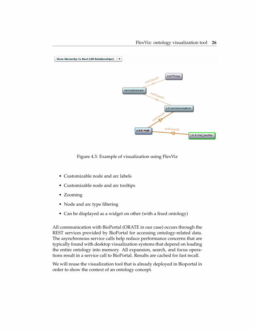
Figure 4.3: Example of visualization using FlexViz
• Customizable node and arc labels
• Customizable node and arc tooltips
• Zooming
• Node and arc type filtering
• Can be displayed as a widget on other (with a fixed ontology)
All communication with BioPortal (ORATE in our case) occurs through theREST services provided by BioPortal for accessing ontology-related data.The asynchronous service calls help reduce performance concerns that aretypically found with desktop visualization systems that depend on loadingthe entire ontology into memory. All expansion, search, and focus opera-tions result in a service call to BioPortal. Results are cached for fast recall.
We will reuse the visualization tool that is already deployed in Bioportal inorder to show the context of an ontology concept.
Web Services 27
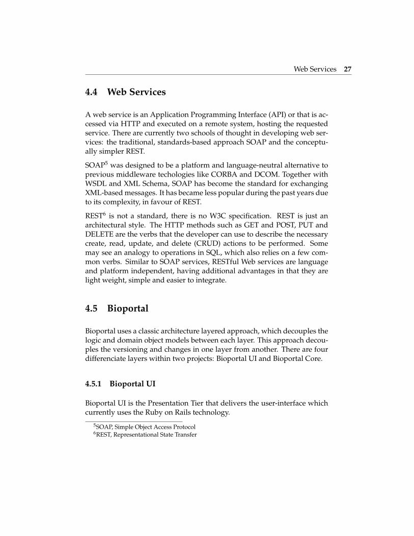
4.4 Web Services
A web service is an Application Programming Interface (API) or that is ac-cessed via HTTP and executed on a remote system, hosting the requestedservice. There are currently two schools of thought in developing web ser-vices: the traditional, standards-based approach SOAP and the conceptu-ally simpler REST.
SOAP5 was designed to be a platform and language-neutral alternative toprevious middleware techologies like CORBA and DCOM. Together withWSDL and XML Schema, SOAP has become the standard for exchangingXML-based messages. It has became less popular during the past years dueto its complexity, in favour of REST.
REST6 is not a standard, there is no W3C specification. REST is just anarchitectural style. The HTTP methods such as GET and POST, PUT andDELETE are the verbs that the developer can use to describe the necessarycreate, read, update, and delete (CRUD) actions to be performed. Somemay see an analogy to operations in SQL, which also relies on a few com-mon verbs. Similar to SOAP services, RESTful Web services are languageand platform independent, having additional advantages in that they arelight weight, simple and easier to integrate.
4.5 Bioportal
Bioportal uses a classic architecture layered approach, which decouples thelogic and domain object models between each layer. This approach decou-ples the versioning and changes in one layer from another. There are fourdifferenciate layers within two projects: Bioportal UI and Bioportal Core.
4.5.1 Bioportal UI
Bioportal UI is the Presentation Tier that delivers the user-interface whichcurrently uses the Ruby on Rails technology.
5SOAP, Simple Object Access Protocol6REST, Representational State Transfer

Bioportal 28
4.5.2 Bioportal Core
Bioportal Core it is composed of the following layers:
Interface Tier Consists of both REST and SOAP Web Services7 that presentall BioPortal capabilities to the upper tiers (e.g., upload ontology,download ontology, display concept, administrative functions, etc).Bioportal UI is primarly driven by the REST services. Using this webservices another organizations could implement a completely differ-ent UI than that currently exposed by the BioPortal. Or, one couldsimply want to consume a single REST services for integrating into aback-end workflow with no UI at all.
This tier include Web Services to get ontology metadata, to get ontol-ogy content, to download an ontology, and to search ontologies. Eachontology in BioPortal is indexed with a stable ontology identifier andis the same for all versions of the same ontology, ontology versionsare indicated by a version identifier, which changes from one versionto the next. BioPortal Web services provide a list of the latest ver-sions of all BioPortal ontologies, enable callers to find an ontologyidentifier based on a version identifier, find all version identifiers fora specific ontology, and list ontology categories. Web services to getontology content include services to get all root concepts, get childrenor parents of a specific concept, and get details of a concept.
Business Logic Tier Uses the Spring technology which enables a partnerto insert any software implementation that abides to the defined in-terfaces.
Persistence Tier Uses the Hibernate technology as a basic object-relationalmapping to the back-end relational database. Hibernate is used forstoring administrative (e.g., user information) and external ontologydata (e.g., ontology attributes specified at upload time). All ontologycontent is stored in Protege and LexGrid as shown in the BusinessLogic layer.
7See NCBO REST Web Services documentation to learn about consuming the BioPortalREST services: http://www.bioontology.org/wiki/index.php/NCBO_REST_services
Bioportal 29
Figure 4.4: Bioportal arquitecture
Chapter 5
Software architecture anddesign
5.1 Architecture overview
Mappingstool is an extension built on top of Bioportal UI, where the mainlogin of the applications runs on the browser side, using Javascript makingextensive use of AJAX. These asynchronous calls that interacts with theserver makes the corresponding operations (query, create, update, delete)to the data layer.
We have used the same approach that Bioportal UI uses with the frame-work Rails to extend it. We have created some controllers on the frontendBioportal UI (Ruby on Rails) that retrieves information from the Model,having as data sources the external RESTful Web Services (Bioportal Core)and the internal database built in MySQL.
More precisely, here it is a brief overview of the tipical interaction betweenthe browser and Mappingstool:
• A user makes an HTTP request to the application, then the serverreceives the request and send the response to the browser.
• When the browser finishes to load the page, the browser is waitinguntil an event is fired by the user.

Architecture overview 31
• If the user clicks on an ontology source or target, browse the concepttree, load a mapping, etc. We make AJAX calls to the server.
• This AJAX calls retrieves information from either Bioportal Core WebServices or the MySQL database that Biportal UI handles.
From the point of view where the code is executed, we can clearly differen-ciate two different approaches in the arquitecture of Mappingstool: serverand client side.
5.1.1 Client side
The majority of the logic of Mappingstool is written in Javascript to be exe-cuted by the browser. It interacts with the server-side code of Bioportal UImaking use of AJAX.
We have tried to modularize the code, so that we produce reusable andmaintenable components. As we explained in the last chapter, we makeuse of several jquery plugins that are used internally in each component,except the jQuery history and jQuery layout. Each component is a class1
that makes use of the jQuery plugins mentioned in the last chapter, be-ing independent and not accesing the global state of the application (someneeded data and dependencies with other components is injected).
The file ’/public/javascripts/mappingstool/controller.js’ is the starting pointof the application, where you can set the components that you want to loadand the main configuration for the different components and jQuery plu-gins. Every component and function is in the scope of bioportal object, sothat we do not have conflicts with other Javascript libraries.
When the page is loaded we need to initialize the components, the layoutand the history:
/**
* Initialize the layout and components, making the appropiate requests
* according to the current state (hash url)
*/
bioportal.mappings.init = function() {
1Javascript is commonly considered procedural, but it is still possible to define customobjects that behave, in many ways, like classes in C or Java.
Architecture overview 32
bioportal.mappings.initLayout();
// Initialize the history
$.historyInit(bioportal.mappings.util.loadPageFromUrlParams);
bioportal.mappings.initComponents();
}
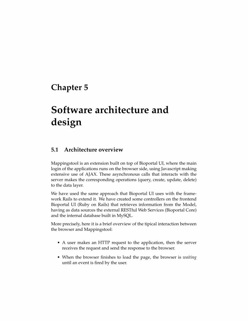
The main components are:
Conceptinfo It is used to show the information about a given concept on-tology. It retrieves the concept information (label, id, fullId, etc.),the graph visualization and the mappings that this concept has withother ontologies. It is reused for the source and target ontology.
Mappingstable It is the component that shows a table (using jQgrid) withthe mappings of the source and target ontologies. When the ontologysource or target ontology changes it fires a event to this component.The data can be sorted, filtered, exported in RDF, etc.
Treeview It retrieves the concept hierarchy of a ontology and display it in atree. The user can also search a concept withing the current ontology.When you click on a concept it refresh the Conceptinfo component.
As a sample code, in the following function we initialize the components:
/**
* Init the components to use (conceptinfo, mappingstable and treeviews)
* according to the global state. It is called just once when the page
* is ready and the layout has been initialized.
*/
bioportal.mappings.initComponents = function () {
[...]
M.sourceTreeviewComp = new M.treeviewComponent.treeview(
M.util.idOntologyVersionSource, M.util.idOntologySource,
M.util.idConceptSelectedSource, M.util.labelConceptSelectedSource,
{ selectorTree: ’.simpleTree’,
selectorTreeWrapper: ’.ui-layout-west’,
identifier: ’source’,

Architecture overview 33
init: true }, M.sourceConceptInfoComp);
[...]
M.mappingsTableComp = new M.mappingstableComponent.mappingstable(
M.util.idOntologySource, M.util.idOntologyTarget,
{ selectorMappingsGrid: ’#list-mappings’,
selectorMappingsGridPager: ’#list-mappings-pager’,
selectorContainer: ’#mappings-source-target-tab’,
init: true });
}
Figure 5.1: Main components
5.1.2 Server side
The directory structure of the whole Bioportal UI is the convention takenfrom Ruby on Rails2.
2See Appendix D

UI overview 34
We have created and modified some Controllers3 that handles the differentactions needed by Mappingstool. The controller access the Model handlingthe internal database that has Bioportal UI and also from the REST WebServices from Bioportal Core. Once we get the data, we render it into aView such as JSON, XML, RDF or HTML.
Mappingstool makes extensive use of the REST web services of the Inter-face tier (Bioportal Core), between others the following actions: authenti-cate a user, get all ontologies, find all version identifiers for a specific ontol-ogy, get all root concepts for a specific ontology, get children or parents ofa specific concept, and get details of a concept.
In the following sample code we have an action that retrieves the informa-tion of an ontology concept, located in the Controller mappingstool (usedin the client-side component Conceptsinfo). DataAccess object provides aninterface to Bioportal Core Web Services, and Mapping is an ActiveRecordobject (belongs to the Model) that access the MySql database of BioportalUI. Then we render the View node info injecting the variables we have takenfrom the Model.
def node_info
@concept = DataAccess.getNode(params[:ontology], params[:id])
@ontology = DataAccess.getOntology(params[:ontology])
@mappings = Mapping.find(:all, :conditions =>
{:source_ont => @concept.ontology_id, :source_id => @concept.id})
render :partial => ’node_info’
end
5.2 UI overview
5.2.1 Flexibility
With the use of the plugin jQuery Layout the tool gains flexibility. Youcan hide and show sections of the tool or expand or contract them withoutrefreshing the page. This is very convenient for instance when you have anontology with a lot of concepts and you want to see the entire tree, or whenyou want to be able to see bigger the concept graph.
3See subsection 4.1.1

UI overview 35
Figure 5.2: Flexibility of the main screen, we can expand or collapse themarked zones.
5.2.2 Usability
We have tried to create a rich experience where all the use cases could bedone without refreshing the page. Integrating jQuery history, we have allthe functionality that could be in a conventional webpage bookmarking thecurrent state or going forward and backward.
Mappingstool has been reviewed by ontology curators providing feedbackabout the different components. This enables the mapping curator to lookfor different ontologies, create a mapping, look at the context, create a note,etc. easily and without losing the current state of your page.
5.2.3 Mockups
We created several mockups with the expected layout of the web applica-tion, and its main use cases. We used Wireframe Sketcher4 to create them.
There are more mockups in Appendix A.
4It is an Eclipse plugin to create mockups and wireframes, more information at http://wireframesketcher.com/
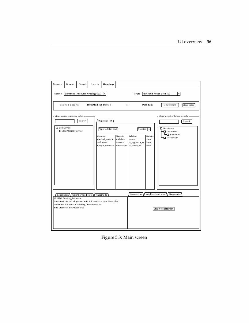
UI overview 36
Figure 5.3: Main screen

Chapter 6
Main use cases
We will now present the main use cases that the extension covers.
6.1 Browse and search ontology concepts
For this, the user first has to choose an ontology with concepts of interestparticipating in a mapping, either as the source or the target ontology. Oncean ontology is selected, a tree view is presented with the hierarchy of theontology, having icons when there are mappings in a specific concept. Alsothe user is able to search a specific concept of the tree.
Figure 6.1: Browse and search ontology concepts
Browse mappings 38
6.2 Browse mappings
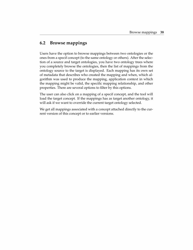
Users have the option to browse mappings between two ontologies or theones from a specif concept (to the same ontology or others). After the selec-tion of a source and target ontologies, you have two ontology trees whereyou completely browse the ontologies, then the list of mappings from theontology source to the target is displayed. Each mapping has its own setof metadata that describes who created the mapping and when, which al-gorithm was used to produce the mapping, application context in whichthe mapping might be valid, the specific mapping relationship, and otherproperties. There are several options to filter by this options.
The user can also click on a mapping of a specif concept, and the tool willload the target concept. If the mappings has as target another ontology, itwill ask if we want to override the current target ontology selected.
We get all mappings associated with a concept attached directly to the cur-rent version of this concept or to earlier versions.
Browse mappings 39
Figure 6.2: Main screen of the application
Information about an ontology concept 40
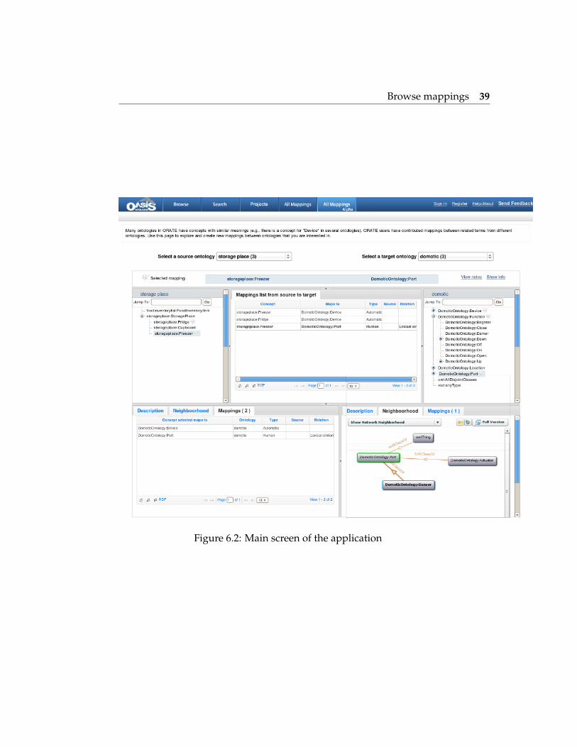
6.3 Information about an ontology concept
When users selects a concept from source or target ontologies, you can seethe description, the neighboorhood and the list of mappings of this conceptwith any other concept (concerning target or any other ontology involvedin the mapping). If you select a mapping, the target ontology is loaded.
Figure 6.3: Information about an ontology concept

Create a mapping 41
6.4 Create a mapping
The main use case is to create mappings between two ontologies. The userchooses a source and a target ontologies, select a concept in each ontologytree and create the mapping. If there is already a mapping between theseconcepts there is an option to view the details (author, date created, rela-tion, map source, map type, etc.).
It creates a new mapping and attach it to the current version of the concept(there could be several versions of the same ontology).
Figure 6.4: Create a mapping
Discussions about a mapping 42
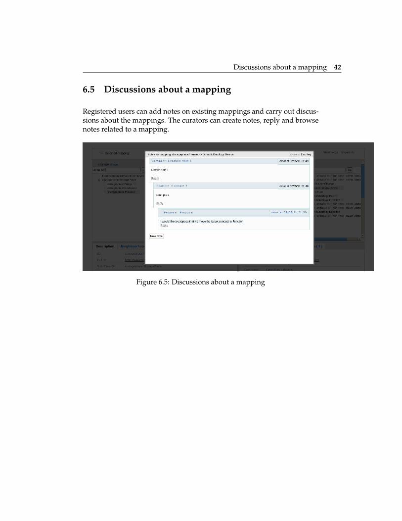
6.5 Discussions about a mapping
Registered users can add notes on existing mappings and carry out discus-sions about the mappings. The curators can create notes, reply and browsenotes related to a mapping.
Figure 6.5: Discussions about a mapping
Visualize the context of a concept 43
6.6 Visualize the context of a concept
In the concept tab a user could visualize the neighborhood of a concept,being really useful to provide the context of a concept withing the ontology.This can be use to compare the contexts of both source and target ontologyconcepts selected.
Export to RDF the mappings between 2 ontologies 44
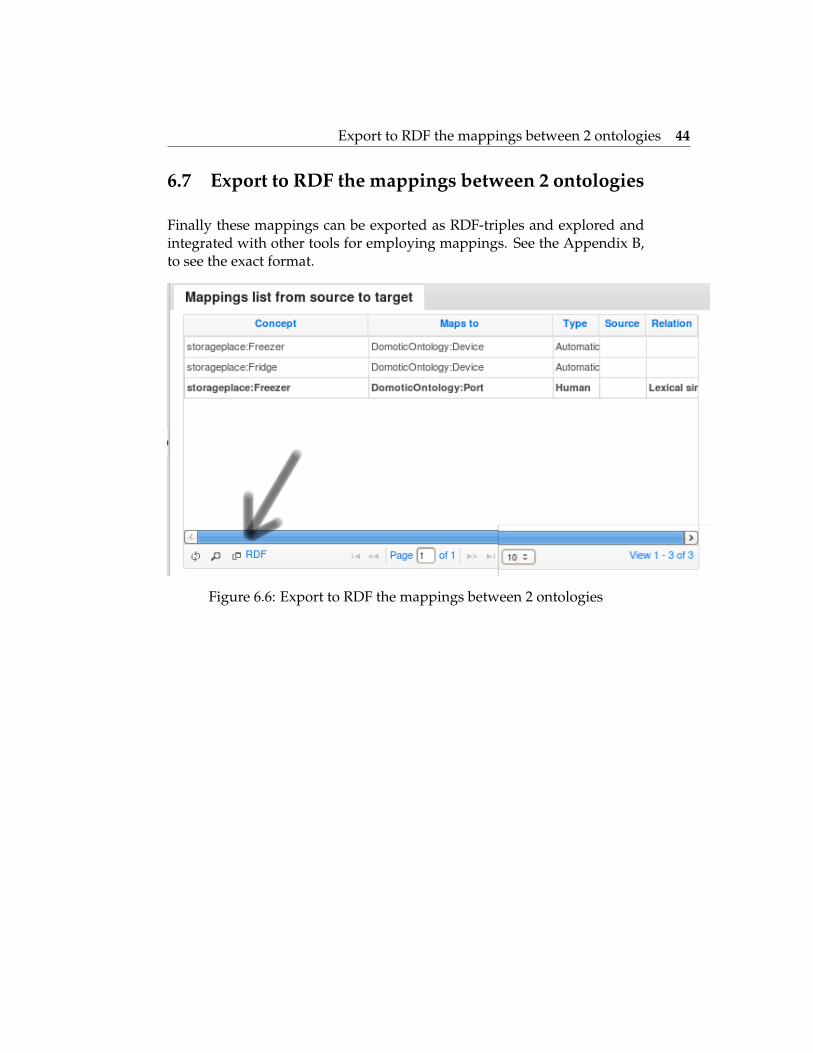
6.7 Export to RDF the mappings between 2 ontologies
Finally these mappings can be exported as RDF-triples and explored andintegrated with other tools for employing mappings. See the Appendix B,to see the exact format.
Figure 6.6: Export to RDF the mappings between 2 ontologies

Chapter 7
Conclusions
BioPortal offers investigators ’one-stop shopping’ on the Web for importantbiomedical ontologies. We have adapted this open source tool to our needs,creating ORATE and extending it with Mappingstool. The incorporationof a variety of Web 2.0 features allows the system to behave not only asa comprehensive ontology repository, but also as general infrastructure tosupport community-based access, peer-review and mapping of ontologycontent.
We have developed a tool that provides a usable and easy tool to createmanual mappings between ontologies, as we gain more experience withmappings in ORATE and as more users start contributing the mappings,we hope that the data that we collect will help us understand the dynamicsof ontology mapping as a collaborative and open process. It is interestingto see how curators of a specif domain (Assistive technologies) use the tooland help each other in the process of mapping concepts.
Mappingtool tries to focus in the Bioportal ecosystem, using his mappingsand ontologies as the data source. As a future work, a promising task willbe to adapt Mappingstool to accept RDF mappings as inputs from Protegeor other mapping format. Also, to be able to use different ontology reposi-tories. And the last step for fully integration, would be to be able to changethe Bioportal instance to use on the fly, in near future Bioportal will be ex-tended to other domains as we did with Assitive Technologies (ORATE).
Possible features to implement in the future could be a graph visualizationof the mappings, automatic mapping and lines between the source and tar-

46
get concepts representing the mappings as it is done in Mapping View (see3.1.2).
We hope that we have helped researchers in the mapping process, allowingthem to know the context of the mapping they try to create and having abetter understanding about the whole picture.

Bibliography
[1] Naveen Balani. The future of the web is semantic. 2005.http://www.ibm.com/developerworks/web/library/wa-semweb/.
[2] Tim; James Hendler Berners-Lee and Ora Lassila. The Semantic Web.Scientific American Magazine, 2001.
[3] G. Bisso. Why and how to define a similarity measure for object based repre-sentation systems. Towards Very Large Knowledge Bases. 1995.
[4] Christoph Bussler. The Semantic Web: research and applications. Springer,2004.
[5] Douglas Crockford. Javascript: the good parts. O’Reilly Media, Inc, 2008.
[6] T. R. Gruber. A translation approach to portable ontologies. KnowledgeAcquisition, 1993.
[7] Musen MA Noy NF. Prompt: Algorithm and tool for automated on-tology merging and alignment. AAAI Press, pages 450–455, 2000.
[8] Jem Rayfield. Bbc world cup 2010 dynamic semantic publishing. 2010.http://bbc.in/d5pM7E.
[9] Xiaomeng Su. A text categorization perspective for ontology mapping. Nor-wegian University of Science and Technology, Norway, 2002.
[10] John Bateman; Alexander Castro; Immanuel Normann; Omar Pera;Leyla Garcia; Jose-Maria Villaveces. Oasis common hyper-ontologicalframework (cof). OASIS Project report, 2010.
Appendix A
Mockups
These are the full list of mockups made before developing the application.
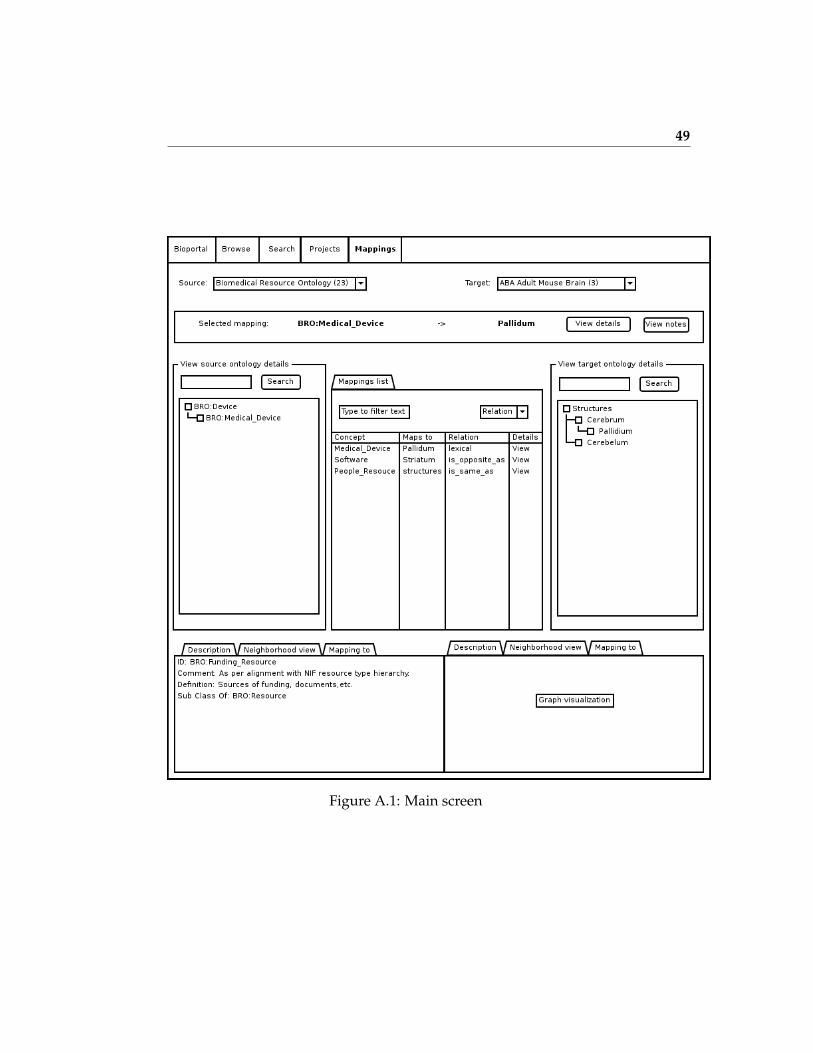
49
Figure A.1: Main screen

50
Figure A.2: Create a mapping

51
Figure A.3: Discussion about a mapping
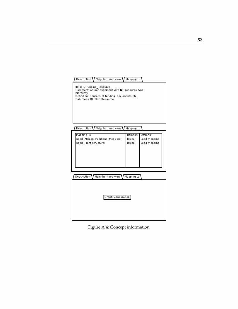
52
Figure A.4: Concept information

Appendix B
RDF Export
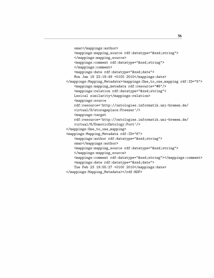
This is a sample of a list of mappings represented in RDF format when youexport them from Mappingstool.
<?xml version=’1.0’ encoding=’UTF-8’?>
<!DOCTYPE rdf:RDF [
<!ENTITY xsd ’http://www.w3.org/2001/XMLSchema#’ >
<!ENTITY a ’http://protege.stanford.edu/system#’ >
<!ENTITY rdfs ’http://www.w3.org/2000/01/rdf-schema#’ >
<!ENTITY mappings ’http://protege.stanford.edu/mappings#’ >
<!ENTITY rdf ’http://www.w3.org/1999/02/22-rdf-syntax-ns#’ >
]>
<rdf:RDF xmlns="http://bioontology.org/mappings/mappings.rdf#"
xml:base="http://bioontology.org/mappings/mappings.rdf"
xmlns:xsd="http://www.w3.org/2001/XMLSchema#"
xmlns:rdfs="http://www.w3.org/2000/01/rdf-schema#"
xmlns:mappings="http://protege.stanford.edu/mappings#"
xmlns:rdf="http://www.w3.org/1999/02/22-rdf-syntax-ns#">
<rdf:Property rdf:about="&mappings;author">
<rdfs:domain rdf:resource="&mappings;Mapping_Metadata"/>
<rdfs:range rdf:resource="&xsd;string"/>
<rdfs:label rdf:datatype="&xsd;string">author</rdfs:label>

54
</rdf:Property>
<rdf:Property rdf:about="&mappings;comment">
<rdfs:domain rdf:resource="&mappings;Mapping_Metadata"/>
<rdfs:range rdf:resource="&xsd;string"/>
<rdfs:label rdf:datatype="&xsd;string">comment</rdfs:label>
</rdf:Property>
<rdf:Property rdf:about="&mappings;confidence">
<rdfs:domain rdf:resource="&mappings;Mapping_Metadata"/>
<rdfs:range rdf:resource="&xsd;string"/>
<rdfs:label rdf:datatype="&xsd;string">confidence</rdfs:label>
</rdf:Property>
<rdf:Property rdf:about="&mappings;date">
<rdfs:domain rdf:resource="&mappings;Mapping_Metadata"/>
<rdfs:range rdf:resource="&xsd;date"/>
<rdfs:label rdf:datatype="&xsd;string">date</rdfs:label>
</rdf:Property>
<rdfs:Class rdf:about="&mappings;Mapping_Metadata">
<rdfs:label rdf:datatype="&xsd;string"
>Mapping_Metadata</rdfs:label>
</rdfs:Class>
<rdf:Property rdf:about="&mappings;mapping_metadata">
<rdfs:domain rdf:resource="&mappings;One_to_one_mapping"/>
<rdfs:range rdf:resource="&mappings;Mapping_Metadata"/>
<rdfs:label rdf:datatype="&xsd;string"
>mapping_metadata</rdfs:label>
</rdf:Property>
<rdf:Property rdf:about="&mappings;mapping_source">
<rdfs:domain rdf:resource="&mappings;Mapping_Metadata"/>
<rdfs:range rdf:resource="&xsd;string"/>
<rdfs:label rdf:datatype="&xsd;string">authority</rdfs:label>
</rdf:Property>
<rdfs:Class rdf:about="&mappings;One_to_one_mapping">
<rdfs:label rdf:datatype="&xsd;string"
>One_to_one_mapping</rdfs:label>
</rdfs:Class>
<rdf:Property rdf:about="&mappings;relation">
<rdfs:domain rdf:resource="&mappings;One_to_one_mapping"/>
<rdfs:range rdf:resource="&xsd;string"/>
<rdfs:label rdf:datatype="&xsd;string">relation</rdfs:label>
</rdf:Property>

55
<rdf:Property rdf:about="&mappings;source">
<rdfs:domain rdf:resource="&mappings;One_to_one_mapping"/>
<rdfs:range rdf:resource="&xsd;string"/>
<rdfs:label rdf:datatype="&xsd;string">source</rdfs:label>
</rdf:Property>
<rdf:Property rdf:about="&mappings;target">
<rdfs:domain rdf:resource="&mappings;One_to_one_mapping"/>
<rdfs:range rdf:resource="&xsd;string"/>
<rdfs:label rdf:datatype="&xsd;string">target</rdfs:label>
</rdf:Property><mappings:One_to_one_mapping rdf:ID="1">
<mappings:mapping_metadata rdf:resource="#2"/>
<mappings:relation rdf:datatype="&xsd;string"></mappings:relation>
<mappings:source
rdf:resource=’http://ontologies.informatik.uni-bremen.de/
virtual/9/storageplace:Freezer’/>
<mappings:target
rdf:resource=’http://ontologies.informatik.uni-bremen.de/
virtual/6/DomoticOntology:Device’/>
</mappings:One_to_one_mapping>
<mappings:Mapping_Metadata rdf:ID="2">
<mappings:author rdf:datatype="&xsd;string">omar
</mappings:author>
<mappings:mapping_source rdf:datatype="&xsd;string">
</mappings:mapping_source>
<mappings:comment rdf:datatype="&xsd;string"><
/mappings:comment>
<mappings:date rdf:datatype="&xsd;date">
Mon Jan 18 22:18:48 +0100 2010</mappings:date>
</mappings:Mapping_Metadata><mappings:One_to_one_mapping rdf:ID="3">
<mappings:mapping_metadata rdf:resource="#4"/>
<mappings:relation rdf:datatype="&xsd;string"></mappings:relation>
<mappings:source
rdf:resource=’http://ontologies.informatik.uni-bremen.de/
virtual/9/storageplace:Fridge’/>
<mappings:target
rdf:resource=’http://ontologies.informatik.uni-bremen.de/
virtual/6/DomoticOntology:Device’/>
</mappings:One_to_one_mapping>
<mappings:Mapping_Metadata rdf:ID="4">
<mappings:author rdf:datatype="&xsd;string">
56
omar</mappings:author>
<mappings:mapping_source rdf:datatype="&xsd;string">
</mappings:mapping_source>
<mappings:comment rdf:datatype="&xsd;string">
</mappings:comment>
<mappings:date rdf:datatype="&xsd;date">
Mon Jan 18 22:18:49 +0100 2010</mappings:date>
</mappings:Mapping_Metadata><mappings:One_to_one_mapping rdf:ID="5">
<mappings:mapping_metadata rdf:resource="#6"/>
<mappings:relation rdf:datatype="&xsd;string">
Lexical similarity</mappings:relation>
<mappings:source
rdf:resource=’http://ontologies.informatik.uni-bremen.de/
virtual/9/storageplace:Freezer’/>
<mappings:target
rdf:resource=’http://ontologies.informatik.uni-bremen.de/
virtual/6/DomoticOntology:Port’/>
</mappings:One_to_one_mapping>
<mappings:Mapping_Metadata rdf:ID="6">
<mappings:author rdf:datatype="&xsd;string">
omar</mappings:author>
<mappings:mapping_source rdf:datatype="&xsd;string">
</mappings:mapping_source>
<mappings:comment rdf:datatype="&xsd;string"></mappings:comment>
<mappings:date rdf:datatype="&xsd;date">
Tue Feb 23 19:55:27 +0100 2010</mappings:date>
</mappings:Mapping_Metadata></rdf:RDF>

Appendix C
Deploying Bioportal Core
The following instructions explains how to build and deploy Bioportal Core.
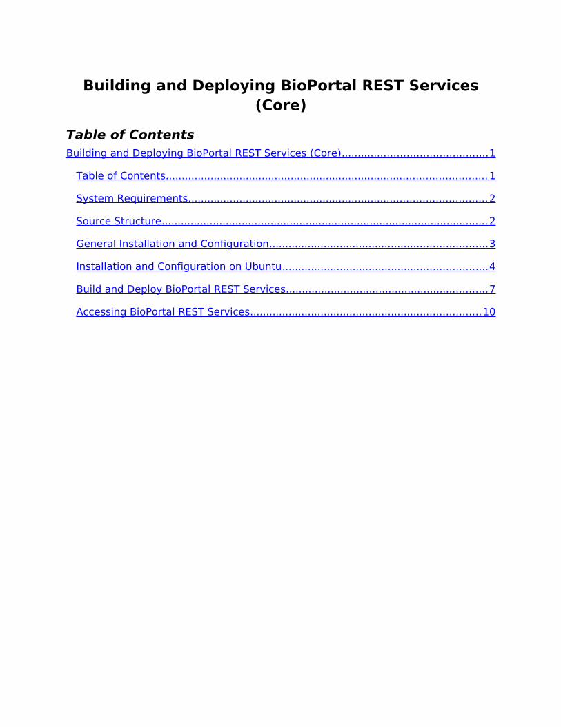
Building and Deploying BioPortal REST Services (Core)
Table of ContentsBuilding and Deploying BioPortal REST Services (Core) ............................................. 1
Table of Contents .................................................................................................... 1
System Requirements ............................................................................................. 2
Source Structure ...................................................................................................... 2
General Installation and Configuration .................................................................... 3
Installation and Configuration on Ubuntu ................................................................ 4
Build and Deploy BioPortal REST Services ............................................................... 7
Accessing BioPortal REST Services ........................................................................ 10

System Requirements1. The Java Development Kit (version 1.5 or higher).
2. Apache Ant (see http://ant.apache.org/ for the latest release).
3. Tomcat Application server (version 5.5 or higher). Although has not been tested, the system should be able to perform equally well on other application servers, such as JBoss, with minimal configuration changes.
4. MySQL 5.0 Database Server.
5. The latest MySQL Connector/J driver (see http://dev.mysql.com/downloads/connector/j/ for the latest release).
Source Structure
build.properties.sampleA template file that contains all build properties with corresponding sample values
build.xml Ant build file
buildAuto-generated folder that contains BioPortal as it is deployed under an application server
classic_to_core_migration
The folder containing source code, database scripts, and instructions on migrating existing data from BioPortal 1.0
dbThe folder containing all relevant database scripts and dumps
distThe folder containing the generated BioPortal Web Application Archive (WAR) file
src BioPortal source code
tmplThe folder containing templates used for generating runtime configuration files and message repository
WebRoot The web application root folder
WebRoot/WEB-INF/conf/generated
The folder containing runtime configuration files, auto-generated
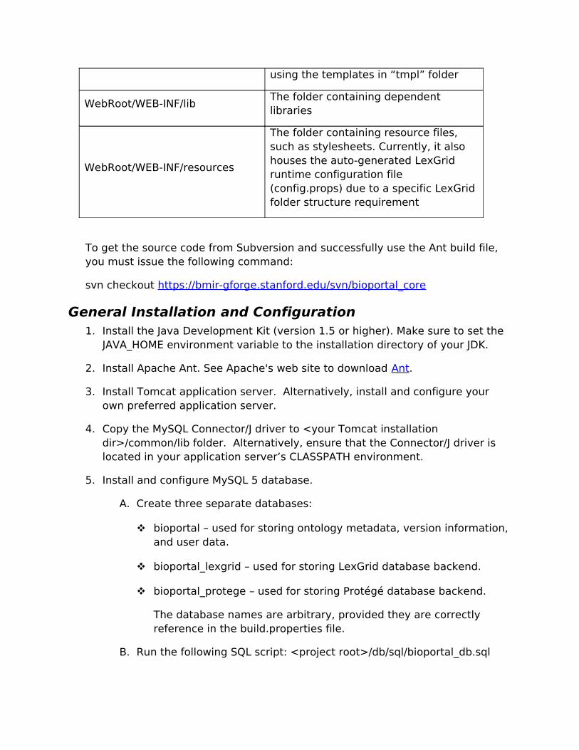
using the templates in “tmpl” folder
WebRoot/WEB-INF/libThe folder containing dependent libraries
WebRoot/WEB-INF/resources
The folder containing resource files, such as stylesheets. Currently, it also houses the auto-generated LexGrid runtime configuration file (config.props) due to a specific LexGrid folder structure requirement
To get the source code from Subversion and successfully use the Ant build file, you must issue the following command:
svn checkout https://bmir-gforge.stanford.edu/svn/bioportal_core
General Installation and Configuration1. Install the Java Development Kit (version 1.5 or higher). Make sure to set the
JAVA_HOME environment variable to the installation directory of your JDK.
2. Install Apache Ant. See Apache's web site to download Ant.
3. Install Tomcat application server. Alternatively, install and configure your own preferred application server.
4. Copy the MySQL Connector/J driver to <your Tomcat installation dir>/common/lib folder. Alternatively, ensure that the Connector/J driver is located in your application server’s CLASSPATH environment.
5. Install and configure MySQL 5 database.
A. Create three separate databases:
bioportal – used for storing ontology metadata, version information, and user data.
bioportal_lexgrid – used for storing LexGrid database backend.
bioportal_protege – used for storing Protégé database backend.
The database names are arbitrary, provided they are correctly reference in the build.properties file.
B. Run the following SQL script: <project root>/db/sql/bioportal_db.sql
C. Run the following SQL script: <project root>/db/sql/bioportal_lookup_data.sql
Ignore the other database scripts. Their artifacts are contained in bioportal_db.sql.
D. Create three dedicated database users, one for each database above:
bioportal_user – used for accessing bioportal database. Grant this user SELECT/CREATE/INSERT/UPDATE/DELETE rights to bioportal database.
bioportal_lexgrid_user – used for accessing bioportal_lexgrid database. Grant this user SELECT/CREATE/INSERT/UPDATE/DELETE rights to bioportal_lexgrid database.
bioportal_protege_user – used for accessing bioportal_protege database. Grant this user SELECT/CREATE/INSERT/UPDATE/DELETE rights to bioportal_protege database.
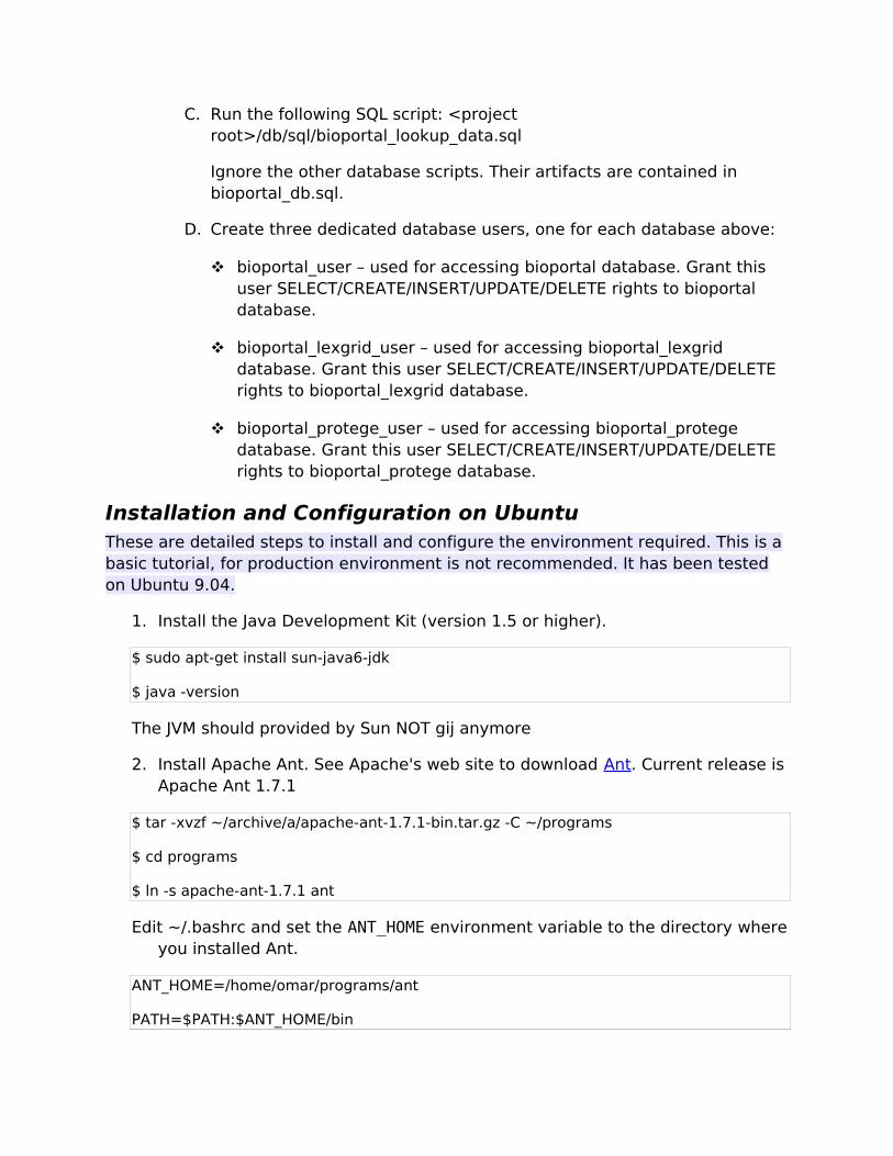
Installation and Configuration on UbuntuThese are detailed steps to install and configure the environment required. This is a basic tutorial, for production environment is not recommended. It has been tested on Ubuntu 9.04.
1. Install the Java Development Kit (version 1.5 or higher).
$ sudo apt-get install sun-java6-jdk
$ java -version
The JVM should provided by Sun NOT gij anymore
2. Install Apache Ant. See Apache's web site to download Ant. Current release is Apache Ant 1.7.1
$ tar -xvzf ~/archive/a/apache-ant-1.7.1-bin.tar.gz -C ~/programs
$ cd programs
$ ln -s apache-ant-1.7.1 ant
Edit ~/.bashrc and set the ANT_HOME environment variable to the directory where you installed Ant.
ANT_HOME=/home/omar/programs/ant
PATH=$PATH:$ANT_HOME/bin
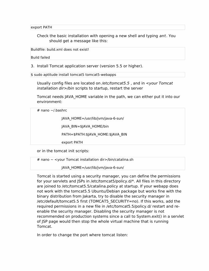
export PATH
Check the basic installation with opening a new shell and typing ant. You should get a message like this:
Buildfile: build.xml does not exist!
Build failed
3. Install Tomcat application server (version 5.5 or higher).
$ sudo aptitude install tomcat5 tomcat5-webapps
Usually config files are located on /etc/tomcat5.5 , and in <your Tomcat installation dir>/bin scripts to startup, restart the server
Tomcat needs JAVA_HOME variable in the path, we can either put it into our environment:
# nano ~/.bashrc
JAVA_HOME=/usr/lib/jvm/java-6-sun/
JAVA_BIN=$JAVA_HOME/bin
PATH=$PATH:$JAVA_HOME:$JAVA_BIN
export PATH
or in the tomcat init scripts:
# nano ~ <your Tomcat installation dir>/bin/catalina.sh
JAVA_HOME=/usr/lib/jvm/java-6-sun/
Tomcat is started using a security manager, you can define the permissions for your servlets and JSPs in /etc/tomcat5/policy.d/*. All files in this directory are joined to /etc/tomcat5.5/catalina.policy at startup. If your webapp does not work with the tomcat5.5 Ubuntu/Debian package but works fine with the binary distribution from Jakarta, try to disable the security manager in /etc/default/tomcat5.5 first (TOMCAT5_SECURITY=no). If this works, add the required permissions in a new file in /etc/tomcat5.5/policy.d/ restart and re-enable the security manager. Disabling the security manager is not recommended on production systems since a call to System.exit() in a servlet of JSP page would then stop the whole virtual machine that is running Tomcat.
In order to change the port where tomcat listen:

$ sudo <editor_you_want> <your Tomcat installation dir>/conf/server.xml
# Modify the port int the connector tag:
<Connector port="8080" maxHttpHeaderSize="8192"
….
4. Install MySQL 5.0 Database Server.
$ sudo aptitude install mysql-server-5.0
5. Get the latest MySQL Connector/J driver (see http://dev.mysql.com/downloads/connector/j/ for the latest release).
6. Copy the MySQL Connector/J driver to <your Tomcat installation dir>/common/lib folder. Alternatively, ensure that the Connector/J driver is located in your application server’s CLASSPATH environment.
7. Configure MySQL 5 database.
A. Set password for a ROOT account on the MySQL5 Server
$ mysqladmin -u root password your-new-password
$ sudo /etc/init.d/mysql restart
B. Create three separate databases:
bioportal – used for storing ontology metadata, version information, and user data.
bioportal_lexgrid – used for storing LexGrid database backend.
bioportal_protege – used for storing Protégé database backend.
The database names are arbitrary, provided they are correctly reference in the build.properties file.
C. Run the following SQL script: <project root>/db/sql/bioportal_db.sql
mysql> SOURCE [<project root>/db/sql/bioportal_db.sql];
mysql> USE [database_name_bioportal];
mysql> SHOW tables; // Just to be sure tables has been created
D. Run the following SQL script:
mysql> SOURCE [<project root>/db/sql/bioportal_lookup_data.sql];
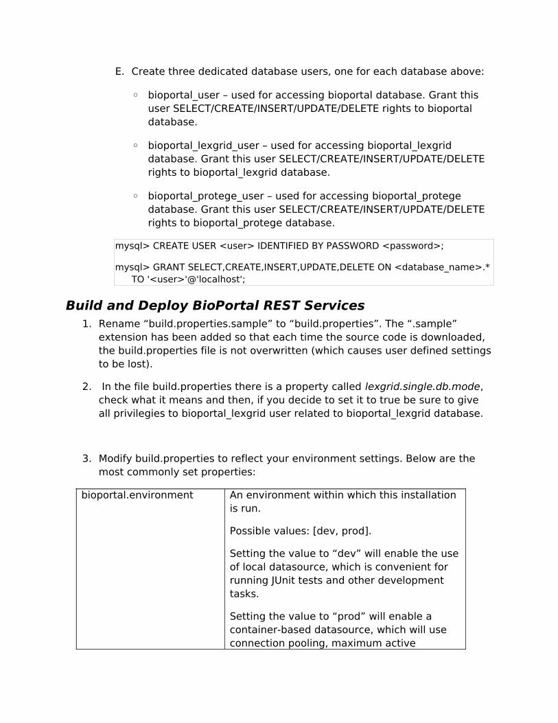
E. Create three dedicated database users, one for each database above:
◦ bioportal_user – used for accessing bioportal database. Grant this user SELECT/CREATE/INSERT/UPDATE/DELETE rights to bioportal database.
◦ bioportal_lexgrid_user – used for accessing bioportal_lexgrid database. Grant this user SELECT/CREATE/INSERT/UPDATE/DELETE rights to bioportal_lexgrid database.
◦ bioportal_protege_user – used for accessing bioportal_protege database. Grant this user SELECT/CREATE/INSERT/UPDATE/DELETE rights to bioportal_protege database.
mysql> CREATE USER <user> IDENTIFIED BY PASSWORD <password>;
mysql> GRANT SELECT,CREATE,INSERT,UPDATE,DELETE ON <database_name>.* TO '<user>'@'localhost';
Build and Deploy BioPortal REST Services1. Rename “build.properties.sample” to “build.properties”. The “.sample”
extension has been added so that each time the source code is downloaded, the build.properties file is not overwritten (which causes user defined settings to be lost).
2. In the file build.properties there is a property called lexgrid.single.db.mode, check what it means and then, if you decide to set it to true be sure to give all privilegies to bioportal_lexgrid user related to bioportal_lexgrid database.
3. Modify build.properties to reflect your environment settings. Below are the most commonly set properties:
bioportal.environment An environment within which this installation is run.
Possible values: [dev, prod].
Setting the value to “dev” will enable the use of local datasource, which is convenient for running JUnit tests and other development tasks.
Setting the value to “prod” will enable a container-based datasource, which will use connection pooling, maximum active

connections, and other configurable settings (see tmpl/context.xml.tmpl for complete list)
bioportal.resource.pathLocation of resource files on the server, such as ontology files, lucene indices, and other filesystem artifacts required at runtime
appserver.home The root directory of your application server
obo.pull.scheduler.enabled
A flag that enables/disables a scheduler job that pulls ontologies from OBO Sourceforge repository.
Possible values: [true/false].
obo.pull.scheduler.cronexpression
A cron expression that defines the time and frequency of the OBO Sourceforge scheduler runs (provided the obo.pull.scheduler.enabled property is set to “true”). Uses standard cron expressions (see http://quartz.sourceforge.net/javadoc/org/quartz/CronTrigger.html for examples)
ontology.parse.scheduler.enabled
A flag that enables/disables a scheduler job that parses ontologies to enable searching/visualization.
Possible values: [true/false].
ontology.parse.scheduler.cronexpression
A cron expression that defines the time and frequency of the ontology parse scheduler runs (provided the ontology.parse.scheduler.enabled property is set to “true”). Uses standard cron expressions (see http://quartz.sourceforge.net/javadoc/org/quartz/CronTrigger.html for examples)
bioportal.smtp.serverThe SMTP server to be used by the application
bioportal.datasource.nameThe name of the BioPortal datasource (used only if the bioportal.environment flag is set to “true”)
bioportal.jdbc.urlJDBC url of the “bioportal” database (see 5A above)
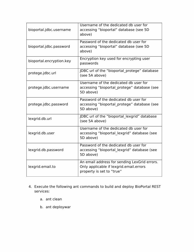
bioportal.jdbc.usernameUsername of the dedicated db user for accessing “bioportal” database (see 5D above)
bioportal.jdbc.passwordPassword of the dedicated db user for accessing “bioportal” database (see 5D above)
bioportal.encryption.keyEncryption key used for encrypting user passwords
protege.jdbc.urlJDBC url of the “bioportal_protege” database (see 5A above)
protege.jdbc.usernameUsername of the dedicated db user for accessing “bioportal_protege” database (see 5D above)
protege.jdbc.passwordPassword of the dedicated db user for accessing “bioportal_protege” database (see 5D above)
lexgrid.db.urlJDBC url of the “bioportal_lexgrid” database (see 5A above)
lexgrid.db.userUsername of the dedicated db user for accessing “bioportal_lexgrid” database (see 5D above)
lexgrid.db.passwordPassword of the dedicated db user for accessing “bioportal_lexgrid” database (see 5D above)
lexgrid.email.toAn email address for sending LexGrid errors. Only applicable if lexgrid.email.errors property is set to “true”
4. Execute the following ant commands to build and deploy BioPortal REST services:
a. ant clean
b. ant deploywar

Accessing BioPortal REST Services1. Start application server.
2. Access BioPortal RESTful URLs. (See http://www.bioontology.org/wiki/images/7/71/BioPortal2.0_User_Guide_v2.doc for details).

Appendix D
Deploying Bioportal UI
The detailed instructions about how to deploy Bioportal UI with Map-pingstool.
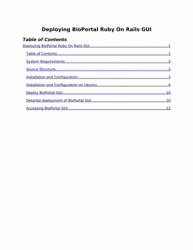
Deploying BioPortal Ruby On Rails GUI
Table of ContentsDeploying BioPortal Ruby On Rails GUI ....................................................................... 1
Table of Contents .................................................................................................... 1
System Requirements ............................................................................................. 2
Source Structure ...................................................................................................... 2
Installation and Configuration ................................................................................. 3
Installation and Configuration on Ubuntu ................................................................ 4
Deploy BioPortal GUI ............................................................................................. 10
Detailed deployment of BioPortal GUI ................................................................... 10
Accessing BioPortal GUI ......................................................................................... 12
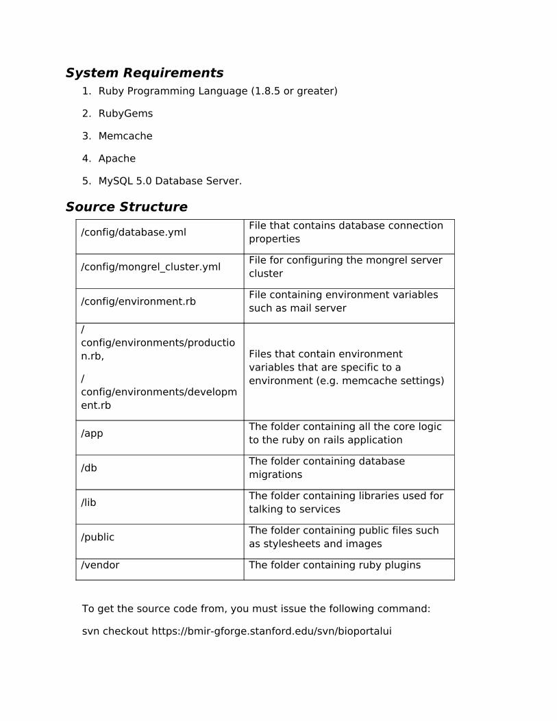
System Requirements1. Ruby Programming Language (1.8.5 or greater)
2. RubyGems
3. Memcache
4. Apache
5. MySQL 5.0 Database Server.
Source Structure
/config/database.ymlFile that contains database connection properties
/config/mongrel_cluster.ymlFile for configuring the mongrel server cluster
/config/environment.rbFile containing environment variables such as mail server
/config/environments/production.rb,
/config/environments/development.rb
Files that contain environment variables that are specific to a environment (e.g. memcache settings)
/appThe folder containing all the core logic to the ruby on rails application
/dbThe folder containing database migrations
/libThe folder containing libraries used for talking to services
/publicThe folder containing public files such as stylesheets and images
/vendor The folder containing ruby plugins
To get the source code from, you must issue the following command:
svn checkout https://bmir-gforge.stanford.edu/svn/bioportalui

Installation and Configuration1. Install the Ruby Core Library (version 1.8.5 or higher
2. Install Ruby Gems
A. actionmailer (2.1.0, 2.0.2)
B. actionpack (2.1.0, 2.0.2)
C. activerecord (2.1.0, 2.0.2)
D. activeresource (2.1.0, 2.0.2)
E. activesupport (2.1.0, 2.0.2)
F. capistrano (2.4.3)
G. cgi_multipart_eof_fix (2.5.0)
H. daemons (1.0.10)
I. fastthread (1.0.1)
J. gem_plugin (0.2.3)
K. highline (1.4.0)
L. hoe (1.7.0)
M. httpclient (2.1.2)
N. memcache-client (1.5.0)
O. mongrel (1.1.5)
P. mongrel_cluster (1.0.5)
Q. mysql (2.7)
R. net-scp (1.0.1)
S. net-sftp (2.0.1)
T. net-ssh (2.0.3)
U. net-ssh-gateway (1.0.0)
V. rails (2.1.0, 2.0.2)
W. rake (0.8.1)
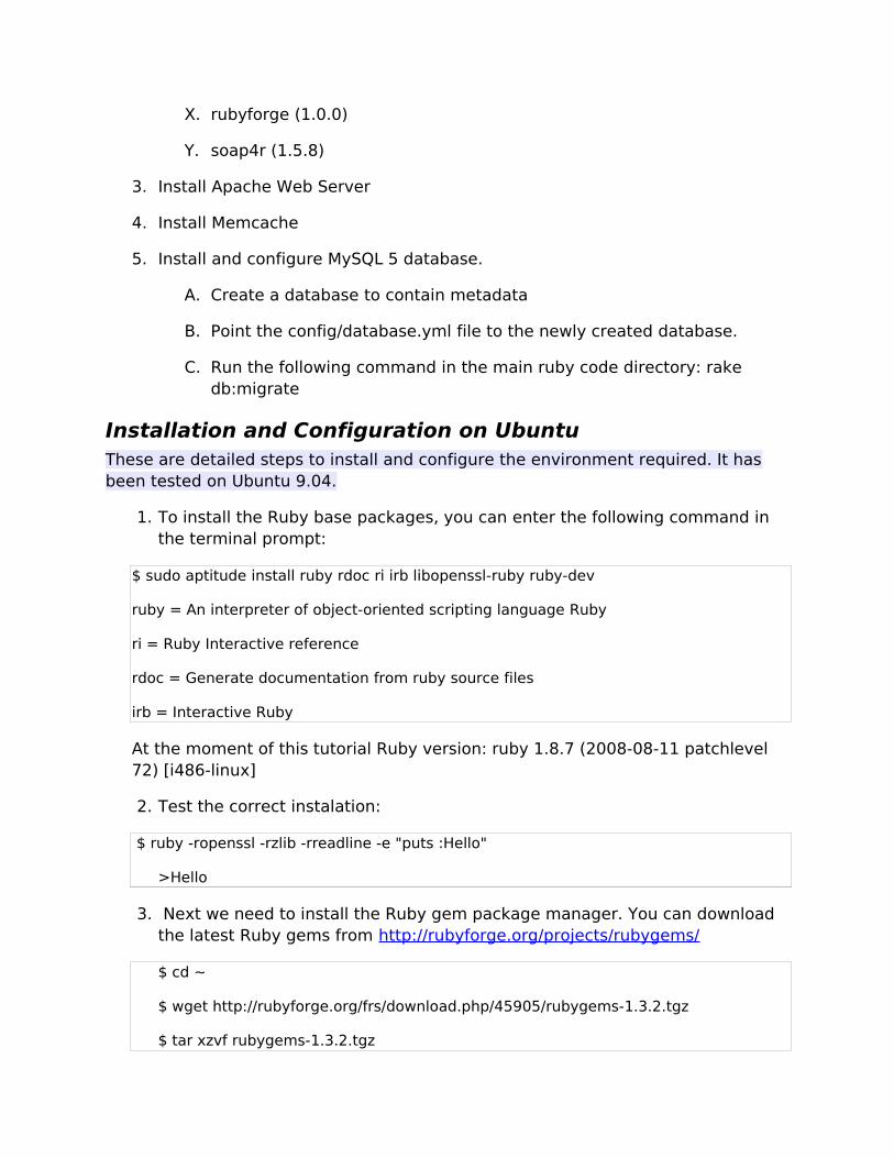
X. rubyforge (1.0.0)
Y. soap4r (1.5.8)
3. Install Apache Web Server
4. Install Memcache
5. Install and configure MySQL 5 database.
A. Create a database to contain metadata
B. Point the config/database.yml file to the newly created database.
C. Run the following command in the main ruby code directory: rake db:migrate
Installation and Configuration on UbuntuThese are detailed steps to install and configure the environment required. It has been tested on Ubuntu 9.04.
1. To install the Ruby base packages, you can enter the following command in the terminal prompt:
$ sudo aptitude install ruby rdoc ri irb libopenssl-ruby ruby-dev
ruby = An interpreter of object-oriented scripting language Ruby
ri = Ruby Interactive reference
rdoc = Generate documentation from ruby source files
irb = Interactive Ruby
At the moment of this tutorial Ruby version: ruby 1.8.7 (2008-08-11 patchlevel 72) [i486-linux]
2. Test the correct instalation:
$ ruby -ropenssl -rzlib -rreadline -e "puts :Hello"
>Hello
3. Next we need to install the Ruby gem package manager. You can download the latest Ruby gems from http://rubyforge.org/projects/rubygems/
$ cd ~
$ wget http://rubyforge.org/frs/download.php/45905/rubygems-1.3.2.tgz
$ tar xzvf rubygems-1.3.2.tgz

$ cd rubygems-1.3.2
$ sudo ruby setup.rb
$ sudo ln -s /usr/bin/gem1.8 /usr/bin/gem
Once it’s done you can delete the .tgz file and rubygems directory.
4. (Optional) We can to create a set of simlinks, otherwise it will be a tedious task to type commands with the version (1.8).
$ sudo ln -s /usr/bin/gem1.8 /usr/local/bin/gem
$ sudo ln -s /usr/bin/ruby1.8 /usr/local/bin/ruby
$ sudo ln -s /usr/bin/rdoc1.8 /usr/local/bin/rdoc
$ sudo ln -s /usr/bin/ri1.8 /usr/local/bin/ri
$ sudo ln -s /usr/bin/irb1.8 /usr/local/bin/irb
5. Install Rails via RubyGems and the gems mentioned on the previous section.
$ sudo gem install rails
6. Install MySQL 5.0 Database.
By default, Rails includes the sqlite3 gem and is automatically configured to use it. To use MySQL instead, follow the following steps:
$ sudo apt-get install mysql-server-5.0 mysql-client-5.0
$ sudo apt-get install libmysql-ruby libmysqlclient-dev
$ sudo gem install mysql
Rails assumes that the MySQL socket file will be found in /tmp/mysqld.sock. In Debian/Ubuntu, this is not the case. Be sure to change database.yml to reflect the actual location of the socket file. (it will be located on /var/run/mysqld/mysqld.sock or /var/lib/mysql/mysql.sock
7. To build the necessary databases and tables ( development, test and production configured on config/database.yml):
$ cd <path_rails_app>
$ rake db:create
$ rake db:migrate
8. Installing Memcache system

1. Introduction
Bioportal UI uses MemCached, a distributed memory object caching system intended for use in speeding up dynamic web applications by alleviating database load. (http://www.danga.com/memcached/)
MemCached is the server library which runs the caching daemon, a client library that interact with the server is required.
Bioportal has choose Ruby MemCache client (http://www.deveiate.org/projects/RMemCache/)
2. Memcached installation
Memcached is packaged for Ubuntu Jaunty, so:
$ sudo aptitude install memcached
We then started a memcached instance:
$ memcached -d -l 127.0.0.1 -p 11299 -m 1024
* -d = run as a daemon
* -l <ip address> = bind to ip address
* -p <port> = run on this port
* -m <num> = use num Mb of memory for the store
* -P = where to put the pid file
* -vv = extra verbose and doesn't daemonize
3. Ruby memcached binding installation: Ruby-Memcache
# sudo gem install Ruby-MemCache
It install an old version (currently 0.0.1), in order to install the last version download from http://www.deveiate.org/projects/RMemCache/ the last gem.
At this point we suggest to make all the changes in order to deploy Bioportal correctly ( Memcache options, database, Bioportal REST URL, etc.) before the next step. Read the next section and returns to this point.
Check that everything works OK with the built-in server of Ruby (WEBrick)
$ ./script/server
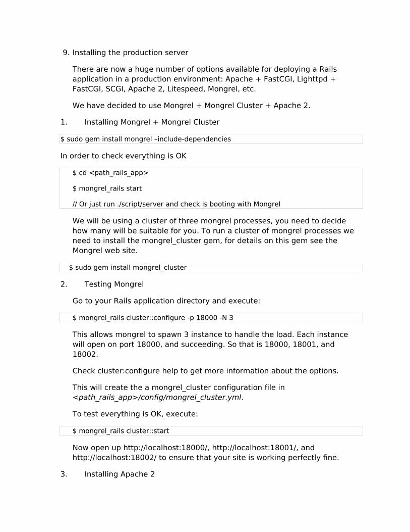
9. Installing the production server
There are now a huge number of options available for deploying a Rails application in a production environment: Apache + FastCGI, Lighttpd + FastCGI, SCGI, Apache 2, Litespeed, Mongrel, etc.
We have decided to use Mongrel + Mongrel Cluster + Apache 2.
1. Installing Mongrel + Mongrel Cluster
$ sudo gem install mongrel –include-dependencies
In order to check everything is OK
$ cd <path_rails_app>
$ mongrel_rails start
// Or just run ./script/server and check is booting with Mongrel
We will be using a cluster of three mongrel processes, you need to decide how many will be suitable for you. To run a cluster of mongrel processes we need to install the mongrel_cluster gem, for details on this gem see the Mongrel web site.
$ sudo gem install mongrel_cluster
2. Testing Mongrel
Go to your Rails application directory and execute:
$ mongrel_rails cluster::configure -p 18000 -N 3
This allows mongrel to spawn 3 instance to handle the load. Each instance will open on port 18000, and succeeding. So that is 18000, 18001, and 18002.
Check cluster:configure help to get more information about the options.
This will create the a mongrel_cluster configuration file in <path_rails_app>/config/mongrel_cluster.yml.
To test everything is OK, execute:
$ mongrel_rails cluster::start
Now open up http://localhost:18000/, http://localhost:18001/, and http://localhost:18002/ to ensure that your site is working perfectly fine.
3. Installing Apache 2

$ sudo apt-get install apache2
$ sudo a2enmod proxy_balancer
$ sudo a2enmod proxy_http
$ sudo a2enmod rewrite
4. Configure Apache and the Balacing Proxy
You have X mongrel servers running, ready to handle incoming requests. But, you want your visitors to use ‘myapp.com’ or just an IP address and not an IP address with different port numbers. This is where Apache comes in.
Create a new file in /etc/apache2/sites-available named 'bioportal' and add the following:
<proxy balancer://mongrel_cluster>
BalancerMember http://127.0.0.1:18000
BalancerMember http://127.0.0.1:18001
BalancerMember http://127.0.0.1:18002
</proxy>
Listen 10000
# Set the port you want to listen the requests for your application
<VirtualHost *:10000>
#ServerName myapp.com
#ServerAlias www.myapp.com
DocumentRoot "path_to_public_dir"
<directory "path_to_public_dir">
Options FollowSymLinks
AllowOverride None
Order allow,deny
Allow from all
</directory>
RewriteEngine On
RewriteCond %{DOCUMENT_ROOT}/system/maintenance.html -f
RewriteCond %{SCRIPT_FILENAME} !maintenance.html
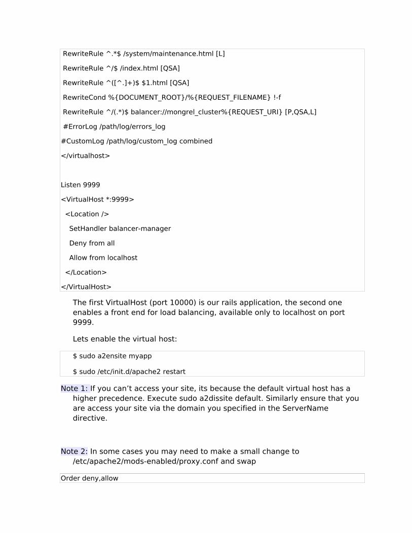
RewriteRule ^.*$ /system/maintenance.html [L]
RewriteRule ^/$ /index.html [QSA]
RewriteRule ^([^.]+)$ $1.html [QSA]
RewriteCond %{DOCUMENT_ROOT}/%{REQUEST_FILENAME} !-f
RewriteRule ^/(.*)$ balancer://mongrel_cluster%{REQUEST_URI} [P,QSA,L]
#ErrorLog /path/log/errors_log
#CustomLog /path/log/custom_log combined
</virtualhost>
Listen 9999
<VirtualHost *:9999>
<Location />
SetHandler balancer-manager
Deny from all
Allow from localhost
</Location>
</VirtualHost>
The first VirtualHost (port 10000) is our rails application, the second one enables a front end for load balancing, available only to localhost on port 9999.
Lets enable the virtual host:
$ sudo a2ensite myapp
$ sudo /etc/init.d/apache2 restart
Note 1: If you can’t access your site, its because the default virtual host has a higher precedence. Execute sudo a2dissite default. Similarly ensure that you are access your site via the domain you specified in the ServerName directive.
Note 2: In some cases you may need to make a small change to /etc/apache2/mods-enabled/proxy.conf and swap
Order deny,allow

Deny from all
for
Order allow,deny
Allow from all
5. Start Mongrel Cluster on Boot
Create a mongrel_cluster conf directory in /etc/mongrel_cluster.
In the Mongrel Cluster gem, there is an init.d script you need to copy.
$ sudo cp /usr/lib/ruby/gems/1.8/gems/mongrel_cluster-0.2.1/resources/mongrel_cluster/mongrel_cluster /etc/init.d
Now we need to add the init.d script to startup:
$ sudo chmod +x /etc/init.d/mongrel_cluster
$ sudo update-rc.d mongrel_cluster defaults
$ sudo ln -s <path_rails_app>/config/mongrel_cluster.yml /etc/mongrel_cluster/railsapp
Deploy BioPortal GUI 1. Configure the mongrel_cluster.yml to contain the amount of servers you want
to run and the port you want them to run on (default is 5)
2. Modify the /config/environments/production.rb file to point to the correct location of your memcache server.
3. Modify the /config/environment.rb file to point to the correct SMTP server.
4. Configure apache to point to the mongrel services
Detailed deployment of BioPortal GUI1. config/database.yml → Set your database settings
2. config/environment.rb
A. Comment RAILS_VERSION in order to use the last Rails version installed on your machine.
B. Set REST_URL var with the Bioportal core URL
3. app/views/ontologies/show.html.erb
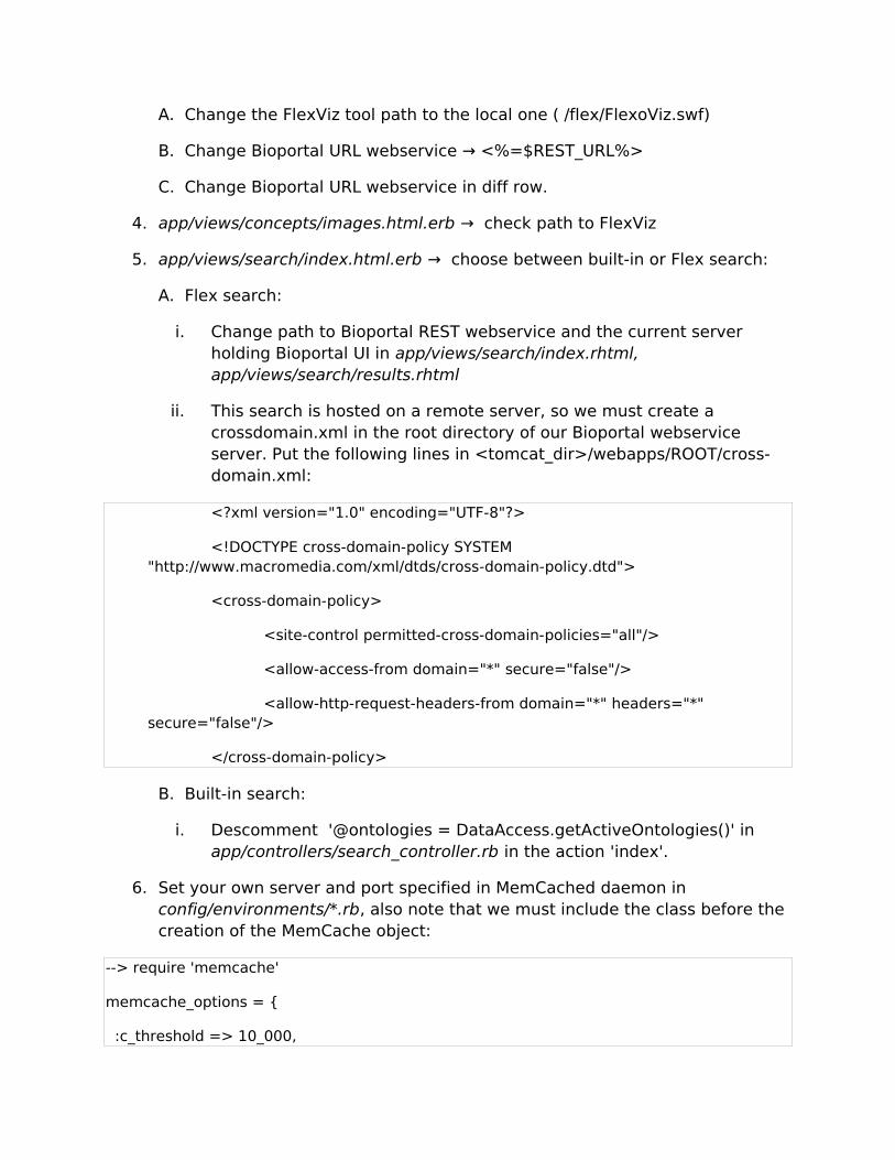
A. Change the FlexViz tool path to the local one ( /flex/FlexoViz.swf)
B. Change Bioportal URL webservice → <%=$REST_URL%>
C. Change Bioportal URL webservice in diff row.
4. app/views/concepts/images.html.erb → check path to FlexViz
5. app/views/search/index.html.erb → choose between built-in or Flex search:
A. Flex search:
i. Change path to Bioportal REST webservice and the current server holding Bioportal UI in app/views/search/index.rhtml, app/views/search/results.rhtml
ii. This search is hosted on a remote server, so we must create a crossdomain.xml in the root directory of our Bioportal webservice server. Put the following lines in <tomcat_dir>/webapps/ROOT/cross-domain.xml:
<?xml version="1.0" encoding="UTF-8"?>
<!DOCTYPE cross-domain-policy SYSTEM "http://www.macromedia.com/xml/dtds/cross-domain-policy.dtd">
<cross-domain-policy>
<site-control permitted-cross-domain-policies="all"/>
<allow-access-from domain="*" secure="false"/>
<allow-http-request-headers-from domain="*" headers="*" secure="false"/>
</cross-domain-policy>
B. Built-in search:
i. Descomment '@ontologies = DataAccess.getActiveOntologies()' in app/controllers/search_controller.rb in the action 'index'.
6. Set your own server and port specified in MemCached daemon in config/environments/*.rb, also note that we must include the class before the creation of the MemCache object:
--> require 'memcache'
memcache_options = {
:c_threshold => 10_000,
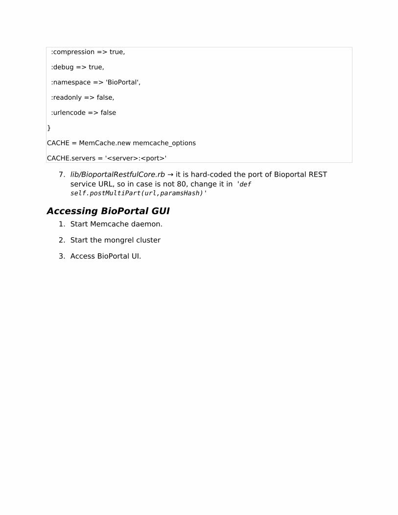
:compression => true,
:debug => true,
:namespace => 'BioPortal',
:readonly => false,
:urlencode => false
}
CACHE = MemCache.new memcache_options
CACHE.servers = '<server>:<port>'
7. lib/BioportalRestfulCore.rb → it is hard-coded the port of Bioportal REST service URL, so in case is not 80, change it in 'def self.postMultiPart(url,paramsHash)'
Accessing BioPortal GUI1. Start Memcache daemon.
2. Start the mongrel cluster
3. Access BioPortal UI.