Communications Infrastructure Specifications, Standards...
23
Communications Infrastructure Specifications, Standards and Practices December 2014 Prepared by: University of Toronto Information Technology Services Enterprise Infrastructure Solutions
-
Upload
nguyenkiet -
Category
Documents
-
view
225 -
download
0
Transcript of Communications Infrastructure Specifications, Standards...
Communications Infrastructure Specifications,
Standards and Practices
December 2014
Prepared by: University of Toronto Information Technology Services Enterprise Infrastructure Solutions
University of Toronto Communications Infrastructure Specifications, Standards and Practices
December 2014 2
Table of Contents
1. OVERVIEW ............................................................................................................... 3
2. GENERAL .................................................................................................................. 3
3. WORK AREA AND PROJECT RESTORATION ................................................ 5
4. EMERGENCIES ....................................................................................................... 6
5. X-RAY AND HOLE CORING ................................................................................. 6
6. KEY ACCESS ............................................................................................................ 6
7. FIRE DETECTION SYSTEMS ............................................................................... 6
8. BUILDING ENTRANCE FACILITY (BEF) SPECIFICATIONS ....................... 6
9. TELECOMMUNICATIONS ROOMS (TR) SPECIFICATIONS ....................... 9
10. ELECTRICAL ......................................................................................................... 12
11. PATHWAYS .......................................................................................................... 122
12. INTERBUILDING CABLE AND HARDWARE ( Between Buildings) ....... 15
13. INTRABUILDING CABLE AND HARDWARE (Within Buildings) .......... 16
14. HORIZONTAL CABLING AND HARDWARE ................................................. 17
15. OUTLET PLACEMENT ........................................................................................ 17
16. WIRELESS ............................................................................................................... 18
17. CABLE SPECIFICATIONS ................................................................................... 19
18. FIBRE TERMINATION ......................................................................................... 19
19. COMPONENT INSTALLATION ........................................................................ 19
20. ‘AS BUILT’ DOCUMENTATION ........................................................................ 19
21. TESTING .................................................................................................................. 20
22. LABELING .............................................................................................................. 21
University of Toronto Communications Infrastructure Specifications, Standards and Practices
December 2014 3
1. OVERVIEW
This document details the general requirements and installation practices developed by and in use at the University of Toronto. This document includes specifications for horizontal, intra-building and inter-building wiring some of which may not be part of the scope of work detailed in the specific work order or project tender documents. This document is to be used as a reference for contractors performing work on the communications infrastructure at the University.
All work shall be performed in accordance with this document unless further details are provided in the Scope of Work section in the work order or tender specification specific to each project.
The following changes to the previous release (November 2010) of this document have been made.
1. Multimode fibre cables of all types (OM1, OM3, and OM4) have been excluded from specifications. Current and future fibre installations to be single mode (SM) only.
2. UTP Cat3 100 pair cables have been excluded (replaced with 25 pair Cat3/Cat5e UTP cables where applicable)
3. Vertical riser Cat5e 25 pair intra-building UTP cables have been excluded. 4. Voice cables excluded as class. Cables used in VoIP and united communications are data cables. 5. Predictive wireless site survey made mandatory. Standards and specifications for wireless
installations have been augmented.
2. GENERAL
Labour
All cabling installations must be performed by unionized (IBEW) electricians.
Applicable Standards, Guidelines and Practices
All work must conform to industry accepted practices, manufacturers’ component installation guidelines, the Ontario Building Code, the Canadian Electrical Code, The University of Toronto Product and Installation Specifications For Building Data and Voice Communication Cabling, and all applicable standards including but not limited to: Standard Title ANSI/ TIA-568-C.0 Generic Telecommunications Cabling for Customer Premises ANSI/TIA-568-C1 Commercial Building Telecommunications Cabling Standard ANSI/TIA-568-C.2 Balanced Twisted-Pair Telecommunication Cabling and Components
Standard ANSI/TIA-568-C.3 Optical Fiber Cabling Components Standard
University of Toronto Communications Infrastructure Specifications, Standards and Practices
December 2014 4
ANSI/EIA/TIA-569-A Commercial Building Standard for Telecommunications
Pathways and Spaces ANSI/EIA/TIA-606(A) Administration Standard for the Telecommunications
Infrastructure of Commercial Buildings ANSI/EIA/TIA-607(A) Commercial Building Grounding and Bonding Requirements for
Telecommunications ANSI/EIA/TIA-598 Colour Coding of Fiber Optic Cables ANSI/EIA/TIA-455 Test Procedures For Fiber Optics, Cables and Transistors ANSI/EIA/TIA-604-3 FOCIS 3 Fiber Optic Connector Intermatability Standard AN5I/ICEA S-83-596 Fiber Optic Premises Distribution Cable AN5I/ICEA S-83-640 Fiber Optic Outside Plant Communications Cable ANSI/NECA/BICSI -568 Standard For Installing Commercial Building
Telecommunications Cabling CSA T530 Commercial Building Standard for Telecommunications Pathways and Spaces CSA T528 Administration Standard for the Telecommunications
Infrastructure of Commercial Buildings CSA T527 Commercial Building Grounding and Bonding Requirements for
Telecommunications CSA C22.1 Canadian Electric Code Part 1 Ontario Regulation 10/02 Ontario Hydro Electrical Safety Code CSA C22.2 No. 232-M Fiber Optic Cables CSA-C22.2 No. 182.4-M9 Plugs, Receptacles, and Connectors for Communication Systems CSA-C22.2 No.214-94 Communications Cables ISO/IEC 11801 Information technology — Generic cabling for customer premises Where there is divergence between the above standards and the University of Toronto Product and
University of Toronto Communications Infrastructure Specifications, Standards and Practices
December 2014 5
Installation Specifications for Building Data and Voice Communication Cabling the latter shall take precedence.
3. WORK AREA AND PROJECT RESTORATION
General
3.1 The contractor shall be responsible for cleanup of all facilities and buildings related to the project, during and at completion.
3.2 The work site and adjacent areas shall be left in the same condition or cleaner than when starting a shift. This must be done on a daily basis.
3.3 The contractor shall protect building equipment, exterior and interior, in the immediate and adjacent work areas.
3.4 The contractor shall protect existing building finishes and services not affected by the modifications.
Surface Finishes
3.5 The general standard is that existing surfaces must be restored and finished back to the original condition or better. If each condition is not exactly specified in the scope of work it will at the discretion of the Project Manager or Property Manager (PM) to determine the appropriate finish. Contractors must be aware of the site conditions prior to bidding and account for the appropriate resources necessary for this aspect of the project.
3.6 When penetrating surfaces where there is vinyl asbestos tile, cut and lift the tile prior to coring. Use the lifted tile to restore finishes where it is possible.
3.7 When penetrating terrazzo or concrete surfaces the restored surface must be finished using the same materials. A terrazzo patch kit must be used to restore surfaces that have been damaged beyond a 1/4 inch circumference of the penetrating structure. A patch area must be created that uses straight cuts at right angles to each other or to adjacent walls.
3.8 When penetrating carpeted surfaces, cut or lift the carpet prior to coring. Refit the carpet tight to the penetrating structure.
3.9 When penetrating wall or floor slabs both sides must be restored to the existing finish.
3.10 When painting surfaces use one primer / sealer coat of paint and two or more finish coats of paint. Block or brick walls are to be thoroughly sealed prior to finishing.
3.11 Any holes in surfaces created to secure operating equipment must be fully restored.
3.12 Any markings on surfaces such as spray paint or liquid markers must be removed, cleaned and polished where necessary.

University of Toronto Communications Infrastructure Specifications, Standards and Practices
December 2014 6
3.13 Any over painting of structures on to background surfaces may make it necessary to refinish the background area to match the new structure. It is the responsibility of the contractor to pre-determine this condition or to take care in avoiding the situation.
4. EMERGENCIES
The successful contractor must make all of the crew members aware of the emergency phone number should an emergency arise while on site. The emergency number is 978-2222. If calling from a University phone dial the local (8-2222) only. If the situation requires the 911 service dial 9 first if using a University phone (9-911). If 911 is called the University emergency number must also be notified. Each PM will have their own list of contacts within their group and the contact must be notified immediately after making an emergency call.
5. X-RAY AND HOLE CORING
5.1 The contractor will supply all vertical and horizontal hole cores. X-ray of proposed core locations must be performed prior to coring. Under no circumstances should X-rays be performed without the prior notification and approval of the PM.
5.2 When site conditions do not make it feasible to x-ray the contractor must exercise reasonable judgment to evaluate whether there is a chance that coring will cause the severing of electrical, low voltage or any other services that may be in the structure that is being penetrated. The use of hammer chisels may be necessary in some buildings. A thorough inspection of both sides of the surfaces must be performed. A flux scanner to check for live loaded A.C. is to be used prior to any drilling, coring or chiseling. Where applicable the opening of drop ceilings on the undersides of floors including fixed surfaces must be done to expose the break through area. Small diameter pilot holes must be drilled prior to the final coring or chiseling.
5.3 A qualified electrician with access to a circuit scanner must be present during coring or chiseling should any services be severed. The campus police must be contacted immediately using the emergency number should services be severed. The PM must be notified of these occurrences immediately also. Depending on the circumstance the contractor may be asked to begin restoration procedures of severed services immediately.
5.4 Any penetration of structural beams, columns or supports must be cleared by the PM before proceeding.
5.5 Patching and making good of coring is the responsibility of the successful bidder.
6. KEY ACCESS Contractors will have access to passage keys needed to perform the work in the buildings. Typically these keys can be picked up from the University of Toronto Police at 21 Sussex at the beginning of a work shift and must be dropped off at the end of the work shift to the same location.
University of Toronto Communications Infrastructure Specifications, Standards and Practices
December 2014 7
7. FIRE DETECTION SYSTEMS
The fire detection systems in the University can be set off by dust. When work is being performed in close proximity to detectors it is necessary to inform The PM 24 hours prior to the work being performed. The PM will arrange with the University's Fire Marshall to have the local devises de-commissioned prior to the start of work.
8. BUILDING ENTRANCE FACILITY (refer to Fig. 1 and Fig. 2) The term Building Entrance Facility (BEF) as employed by the University of Toronto is the location at which the intra-building communications backbone cabling meets the inter-building communications cabling. Minimum recommended BEF room sizing is 10' x 11' for each 10,000 square-foot area served. This is a secure, strategically located room for each University building with the following attributes:
8.1 The building entrance facility (BEF) shall be constructed with full height walls using steel studs with minimum 5/8 inch drywall.
8.2 All walls shall be painted to match the existing colour and finish. The use of any other colour must be approved by the owner. All existing painted surfaces must be freshly painted including cement floors. All surfaces must have one coat of primer, one intermediate and one or more finish coats of latex or oil based paint.
8.3 Remove any existing carpet from new BEF's and finish the floors as per above or the detailed scope of work.
8.4 A 3/4 inch fire rated plywood backboard is to be securely mounted on top of the new gypsum board wall or existing surface. The exact size and method of installation will be determined by the site conditions.
8.5 Ceiling lights must be provided with a switch located immediately inside the access door to the room. The fixture shall be as a minimum a two tube fluorescent fixture that delivers at least 50 foot candles three feet (one meter) above the finished floor.
8.6 Maintain positive pressure within the BEF with a minimum of one air change per hour. The HVAC shall be provisioned such that the temperature is kept in the range of 18 to 24 C (64 to 75 F) and the humidity is kept between 30 to 55% RH.
8.7 The BEF shall be equipped with a minimum of two standard nineteen inch (19") 44RU equipment racks securely bolted to the floor. A minimum 3 feet (91 cm) clearance on three sides (including front and back) of the racks shall be maintained. Each rack shall be provisioned with vertical cable management. A minimum twelve inch (12") ladder-type cable tray shall be provided from the BEF wall to the equipment rack. If other elements of the building infrastructure must be co-located with the telecommunications facilities in the BEF minimum clearances ( 3 feet) must be maintained and also conform to any applicable Canadian Electrical Code requirements.

University of Toronto Communications Infrastructure Specifications, Standards and Practices
December 2014 8
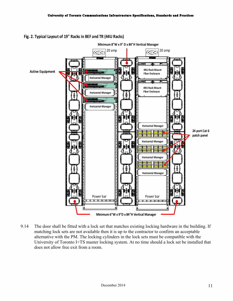
8.8 Cable terminations and equipment placement shall be in general conformance with the typical layout illustrated below (Typical Layout of 19" Racks in BEF and TR). Cable terminations shall be in one rack and active equipment in another unless otherwise specified by the PM.
8.9 Three (3) separately fused, isolated ground duplex electrical outlets with lock on breakers are to be installed. One to be wall mounted and the other two secured to the top of the relay racks. Each equipment rack shall be provided with a minimum eight outlet surge protected power bar horizontally rack-mounted at its bottom. If emergency generator back-up power is available the BEF shall be connected to it.
8.10 Electrical outlets should be 20 (30) A, 208V. Where power draw is expected to be under 1500W, use of 20A, 110V outlets is acceptable.
8.11 Grounding and bonding infrastructure meeting Canadian Electrical Code and ANSI/EIA/TIA 607 requirements shall be routed through all telecommunications rooms and shall terminate on a telecommunications grounding bus bar equipped to handle NEMA compliant grounding hardware. All metallic non-current-carrying conductive parts, including equipment racks, shall be appropriately grounded.
8.12 Solid core wood door painted to match other existing doors or stained and finished where applicable. The door swing shall either be outward or not deemed as usable space.
8.13 The door shall be fitted with a lock set that matches existing locking hardware in the building. If matching lock sets are not available then it is up to the contractor to confirm an acceptable alternative with the Project Manager (PM). The locking cylinders in the lock sets must be compatible with the University of Toronto I+TS master locking system. At no time should a lock set be installed that does not allow free exit from a room.

University of Toronto Communications Infrastructure Specifications, Standards and Practices
December 2014 9
Fig. 1. Building Entrance Facility / TC room
(not to scale)
19" CABLE TERMINATIONRACK
¾” FIRE RETARDANT PLYWOOD BACKBOARD
IDC FIELD
2 (TWO) 20 AMP UTILITY OUTLETS
STATION PATHWAY,FIRE STOPPED
19" EQUIPMENT RACK
INCOMING FACILITIESTRADE SIZE 4" MINIMUM
2 (TWO) 20 AMP IG DEDICATED CIRCUITS
TR - 7' min
LADDER CABLE TRAYWIDTH 12" MINIMUM
INTERCONNECTING CONDUITTRADE SIZE 4" MINIMUM,
FIRE STOPPED
BEF - 10' min
TR - 9' minBEF - 11' min
9. TELECOMMUNICATIONS ROOMS (refer to Fig. 1 and Fig. 2)
9.1 Minimum Telecom Room size is 9' x 7'. Additional TR per floor is required if UTP Cat6 cable distance to a work area exceeds 150 feet (for 10 Gbps runs).
9.2 The telecommunications room (TR) shall be constructed with full height walls using steel studs with minimum 5/8 inch drywall.
9.3 All walls shall be painted to match the existing colour and finish. The use of any other colour must be approved by the owner. All existing painted surfaces must be freshly painted including
University of Toronto Communications Infrastructure Specifications, Standards and Practices
December 2014 10
cement floors. All surfaces must have one coat of primer, one intermediate and one or more finish coats of latex or oil based paint.
9.4 Remove any existing carpet from new TR's and finish the floors as per above or the detailed scope of work.
9.5 A 3/4 inch fire rated plywood backboard is to be securely mounted on top of the new gypsum board wall or existing surface. The exact size and method of installation will be determined by the site conditions.
9.6 Ceiling lights must be provided with a switch located immediately inside the access door to the room. The fixture shall be as a minimum a two tube fluorescent fixture that delivers at least 50 foot candles three feet (one meter) above the finished floor.
9.7 Maintain positive pressure within the TR with a minimum of one air change per hour. The HVAC shall be provisioned such that the temperature is kept in the range of 18 to 24 C (64 to 75 F) and the humidity is kept between 30 to 55% RH.
9.8 The TR shall be equipped with a minimum of one standard nineteen inch (19”) 44RU equipment rack securely bolted to the floor. A minimum 2.5 feet ( 75 cm ) clearance on three sides ( including front and back ) of the rack or cluster of racks shall be maintained. Each rack shall be provisioned with vertical cable management. A minimum six inch ( 6" ) ladder-type cable tray shall be provided from the TR wall to the equipment rack.
9.9 Refer to Typical Layout of 19' Racks in BEF and TR above for an example of cable termination and active equipment placement in a TR equipped with two 19" racks,
9.10 Separately fused, isolated ground duplex electrical outlets with lock on breakers are to be installed. One to be wall mounted and one secured to the top of each of the relay racks. Each equipment rack shall be provided with a minimum six outlet surge protected power bar horizontally rack-mounted at its bottom.
9.11 Electrical outlets should be 20 (30) A, 208V. Where cumulative power draw is expected to be under 1500W, use of 20A, 110V outlets is acceptable.
9.12 Grounding and bonding infrastructure meeting Canadian Electrical Code and ANSI/EIA/TIA 607 requirements shall be routed through all telecommunications rooms and shall terminate on a telecommunications grounding bus bar equipped to handle NEMA compliant grounding hardware. All metallic non-current-carrying conductive parts, including equipment racks, shall be appropriately grounded.
9.13 Solid core wood door painted to match other existing doors or stained and finished where applicable. The door shall open outward where permissible and if that is not the case the swing of the door shall not be counted in the clearances specified for the equipment racks.
University of Toronto Communications Infrastructure Specifications, Standards and Practices
December 2014 11
4RU Rack Mount Fiber Enclosure
4RU Rack Mount Fiber Enclosure
Horizontal Manager
Horizontal Manager
Horizontal Manager
Horizontal Manager
Horizontal Manager
24 port Cat 6 patch panel
Active Equipment
Minimum 6"W x 9"D x 84"H Vertical Manager
Minimum 8"W x 9" D x 84"H Vertical Manager
Horizontal Manager
20 amp20 amp
Power bar Power bar
Horizontal Manager
Fig. 2. Typical Layout of 19" Racks in BEF and TR (44U Racks)
9.14 The door shall be fitted with a lock set that matches existing locking hardware in the building. If matching lock sets are not available then it is up to the contractor to confirm an acceptable alternative with the PM. The locking cylinders in the lock sets must be compatible with the University of Toronto I+TS master locking system. At no time should a lock set be installed that does not allow free exit from a room.
University of Toronto Communications Infrastructure Specifications, Standards and Practices
December 2014 12
10. ELECTRICAL
General
10.1. All electrical work must comply with the latest edition of the Ontario Hydro Safety Code, University of Toronto Electrical Standards, Ontario Building Code and applicable C.S.A. and U.L.C. Standards. Where required, Ontario Hydro inspection shall be applied and paid for by the contractor. Provide certificate prior to final acceptance of work.
10.2. The use of tandem breakers is not permitted.
10.3. All electrical cable must be 12 awg. and installed in 1/2 inch EMT conduit supplied by the contractor and installed directly to the panel location. 12 awg BX is acceptable only when fishing an existing wall.
10.4. The contractor must have a circuit tracer either on site or readily accessible.
10.5. All electrical circuits that have been installed will also require labeling. The panel end of the circuit will indicate that the circuit is a dedicated I+TS circuit and include the room number in which it terminates. The receptacle end of the circuit will indicate the panel number, panel location, and breaker number.
10.6. A lockable breaker is required at the panel.
Isolated Ground
10.7. The isolated ground (IG) receptacle will be orange in colour and wired as an individual branch circuit outlet. The outlet will have a separate green or green/yellow wire which runs continuously from the ground conductor terminal to the first panel board where it is connected to the ground bus. Bonding of the conduit, boxes etc. of the circuit is accomplished by ordinary means (conduit or a separate ground wire). The two grounds are connected only at the panel board.
10.8. The IG outlet is grounded to the same ground as the electrical distribution system. The only difference is that it is connected to ground via a separate wire. There is no `clean' `separate' or `dedicated' ground. The Electrical Safety Code allows only one earthing ground.
11. PATHWAYS Communications cables shall be contained in pathways installed parallel or perpendicular to building lines unless otherwise specified by the Project Manager. When completely contained in conduit the use of CMR (FT-4) rated cable is permitted. When CMP (FT-6) rated cable is specified it shall be supported by J-hooks and/or cable tray when not run in conduit.
University of Toronto Communications Infrastructure Specifications, Standards and Practices
December 2014 13
Interference Drawings
11.1. When requested by the Project Manager, interference drawings must be submitted prior to commencing with the installation of conduits. These drawings must indicate the conduit routing and pull box locations with reference measurements from two walls or permanent fixtures. Include construction notes describing elevation changes, wall penetrations and information with regards to existing fixtures that may be affected by the installation of the conduit. Neatly hand drawn routing and notes on the floor plans provided with the tender are in an acceptable format.
Conduits
11.2. All conduits shall be EMT type installed with steel, set-screw type fittings except on the exterior of the building, which shall be rigid galvanized steel with threaded connectors. Conduit shall be installed in compliance to prevailing codes and standards. Conduits must be installed at right angles and parallel to building grids
11.3. Pull strings must be supplied in all new and reworked conduit.
11.4. No pull elbows or LBs will be installed anywhere. Only sweep or 90deg. elbows will be utilized and no more than two 90deg. bends will be permitted between pull boxes. The minimum radius of curvature shall be 10 times the conduit internal diameter (ID).
11.5. In TRs the conduit shall be installed parallel to the backboard with a 90deg. bend toward the floor or enter within 10 inches of and parallel to the cable tray.
11.6. All conduit ends shall be fitted with plastic bushings.
11.7. All exposed conduit and junction boxes will be painted to match the existing environment. All conduits and pull boxes must be treated and cleaned prior to painting. The conduit must have one coat of primer paint , one intermediate coat and one or more finish coats of paint. Any colour other than the existing environment must be approved by the owner prior to use.
11.8. Maximum distance of conduit run between two pull boxes will be 30 metres. The pull box shall have a screw type cover not hinged. All pull boxes must be accessible with a minimum 24 x 24 inch hinged access hatch provided where required. Pull boxes for vertical conduits must be installed to provide a straight pass through for vertical cables. The sizes of junction boxes shall be 8 times the size of the inside diameter size of the conduit entering it. The exception is when 4 inch conduit is used, and then 30X24X6 inch junction boxes are acceptable. Pull boxes are not to be installed in elevator machine rooms. Conduits installed in elevator machine rooms must provide maximum clearance and must not restrict the service area.
11.9. When conduit is installed in utility closets the conduit must be installed in a steel sleeve that is 6 inches high and the gap between the floor and the sleeve is to be water tight.
11.10. All wall and floor penetrations shall be filled as per code and finished to match the existing surface.

University of Toronto Communications Infrastructure Specifications, Standards and Practices
December 2014 14
Flexible Conduit or Innerduct Tubing
11.11. Innerduct is not to be used unless it is specified in the detailed scope of work.
11.12. If tubing is specified the inside surface must have a smooth finish that will allow it to be fished.
11.13. It must resist crushing pressures and must not collapse within normal bending limits.
11.14. It should have a diameter of not less than 1 inch.
11.15. The contractor must supply manufacturer’s specifications with the tender response if it is specified that details the above requirements.
11.16. Tubing may be specified where ever fibre cable may be subjected to bending forces that would place it at risk of damage.
11.17. Tubing may be specified in transitions when in and out of conduit pathways do not line up.
11.18. Tubing may be specified in telecommunications rooms when cable needs to be installed in free air when other support structures are not feasible.
11.19. Tubing will not be used to overcome problems induced through bad installation practices of other components.
11.20. Fastening of ends of tubing to conduit, racks or tray to be through mechanically sound fittings, not plastic tie wraps.
Cable Tray
11.21. Cable tray specified for telecommunications rooms shall be ladder type cable tray, no less than 6 inches wide in TR and 12 inches wide in BEF by 3.5 inches deep with 8 inch spacing between rungs. Only fittings such as sweeping 30, 45, 60, and 90 degree elbows, tee's and crosses manufactured by the OEM are to be used to change direction. Use fittings of the smallest available bending radius and still accommodate the bending radius of the backbone cabling. Butting two section of tray together to create right angle turns is not acceptable. Any custom alterations to the tray must be approved by the PM prior to installation.
11.22. When tray is running parallel to backboards install it 4 inches off the backboard to allow passage of cables between the tray and the backboard.
11.23. When the tray is adjacent to a wall use right angle brackets or unistrut to support it.
11.24. When the tray it is installed in free air to cross a closet, suspend it from the ceiling using threaded rod.
11.25. When tray is installed above a relay rack use threaded rod to support the tray 12 inches from the top of the rack where possible.
University of Toronto Communications Infrastructure Specifications, Standards and Practices
December 2014 15
12. INTER-BUILDING CABLE AND HARDWARE (between buildings)
12.1. Inter-building cables are the copper and fibre optic backbone cables that connect building to building. Three major categories of inter-building cables are defined on campus: main trunk cables (typically between core router locations), branch cables (from a router location to major cross-connects covering a significant area), and local cables (between building one of each is either small or the last on a cableway)
Backbone cables
12.2. Backbone cables are installed between major facilities hosting Core layer network devices. A loose tube, water block compound filled, fibre cable consisting of at least 96 (ninety six) single mode fibres in a water resistant, armoured jacket shall be installed in a minimum 4 inch duct between buildings.
Branch cables
12.3. Branch cables connect major IT facilities to buildings hosting Distribution layer network devices. A loose tube, water block compound filled, fibre cable consisting of at least 48 (forty eight) single mode fibres in a water resistant, armoured jacket shall be installed in a minimum 4 inch duct between buildings.
Access cables
12.4. Access cables are installed to connect Distribution layer facilities to Access layer facilities (typically smaller standalone buildings).
12.5. A loose tube, water block compound filled, fibre cable consisting of at least twenty four (24) single mode fibres in a water resistant, armoured jacket shall be installed in a minimum 4 inch duct between buildings.
12.6. A multi-pair UTP cable in a water resistant, armoured jacket should be installed between buildings (sharing the 4 inch duct with the fibre cables is acceptable). The cable shall be 25 pair EIA/TIA Category 3 unless otherwise specified by the project scope of work or the PM.
Installation Notes
12.7. All cables will be installed with 10 foot (3 meter) service coils at all termination points and transition closets. Service loops may be stored on backboards, in unoccupied sections of cable tray or in conduit pull boxes. Do not store service loops in the fibre cable in the connector tray.
12.8. The contractor is responsible for the location of buried utilities, where applicable. These arrangements will be made in advance prior to commencement of work. The contractor is also

University of Toronto Communications Infrastructure Specifications, Standards and Practices
December 2014 16
responsible for the restoration of the area under construction to its original condition or better. Where landscape property has been disturbed, the contractor must account for the restoration of grass, plants, walkways, etc.
12.9. Refer to The University of Toronto Product and Installation Specifications for Building Data Communication Cabling for specifics on the types of cables and means of termination.
13. INTRA-BUILDING CABLE AND HARDWARE (Within Buildings)
13.1. Intra-building backbone cables are the copper and fibre optic cables that run between the BEF and the telecommunication rooms within a building.
13.2. As a minimum, the building backbone infrastructure should consist of at least 12 strands singlemode cable between each TR and the BEF. Multimode and/or UTP Cat6 cabling can be added if required.
13.3. Nineteen inch relay racks with 77 inches of usable space (44RU) bolted to the floor shall be installed in each telecommunications room. Rack layouts will include:
a) One 2RU horizontal cable management bracket for every two 24 port fibre or copper patch panels (or one 48 port). Likewise, 2RU horizontal management shall be provisioned for active equipment residing in the rack.
b) One power bar (with internal breaker) mounted switch to the front and outlets on rear utilizing only one rack space.
c) A minimum 6 inch vertical cable management with cable bend control mounted to the side of the rack.
d) A minimum 6 inch wide ladder type tray with 8 inch spacing between rungs to support cables from the TR entry point to the termination locations.
13.4. All backbone copper and fibre inter-building and intra-building cables will be installed with 10 foot (3 meter ) service coils installed at all termination points and transition closets. The service loops may be stored on the backboard, in an inactive section of cable tray or in the conduit pull box.
13.5. Pull string/rope shall remain in all conduit upon completion of cable installation. Backbone and horizontal cable may co-exist in the same conduit. However all fibre cable must be in separate conduit from the copper type where two conduit paths have been installed.
13.6. Refer to The University of Toronto Product and Installation Specifications for Building Data and Voice Communication Cabling for specifics on the types of cables and means of termination.
University of Toronto Communications Infrastructure Specifications, Standards and Practices
December 2014 17
14. HORIZONTAL CABLING AND HARDWARE
14.1. The horizontal distribution cable is the copper or fibre optic cable that runs between the workstation outlet and the rack-mounted patch panel in the telecommunications room.
14.2. Two (2) blue jacketed Category 6 UTP four pair cable shall be installed from the rack-mounted modular patch panel in the TR's through the horizontal conduit infrastructure to the outlet location. Where specified, the fibre cable shall be a 6 (six) strand singlemode cable.
14.3. Drop cables may share the riser conduits when installation occurs between floors. When there is a choice, these drop cables should always be installed in the riser conduit that accommodates the corresponding media type (copper with copper, fibre with fibre).
14.4. One inch conduit will be used between the junction boxes on the horizontal distribution conduits and the user outlet boxes. In many cases the conduit will be surface run down walls to a surface mount outlet box designed to accept a flush mounted modular faceplate installed on the box.
14.5. Cable installation in plenum spaces of buildings is allowed (plenum cable fire rated FT6).
14.6. RJ-45, 8 position jack modules shall be installed as required in the modular faceplate and configured to the EIA/TIA 568A standard. Blanks are to be provisioned for unused spaces in the face plate. Colour coding of jack modules may be requested if applicable (e.g. orange for wireless).
14.7. Refer to The University of Toronto Product and Installation Specifications for Building Data Communication Cabling for specifics on the types of cables and means of termination.
15. OUTLET PLACEMENT
15.1. Standard outlet height when boxes are installed on a wall is 12 inches from the floor.
15.2. Conduit or boxes are not to obstruct the function of any adjacent fixtures.
15.3. When outlets are mounted on the floor the outlet box should be mounted on its widest surface so that the faceplate is on the side of the box and the cover plate is able to be opened.
15.4. Any architectural detail such as elaborate baseboards or outlets mounted at counter level in labs should be addressed by the contractor prior to installing the outlet box if it is not addressed in the detailed scope of work.
15.5. The University reserves the right to relocate any telecommunications outlet by up to 3 metres without penalty before installation is complete.

University of Toronto Communications Infrastructure Specifications, Standards and Practices
December 2014 18
16. WIRELESS SPECIFICATIONS
Wireless AP locations
16.1. For each new wireless installation on campus a predictive wireless site survey shall be performed, and results (WAP layout) incorporated with project documentation at the planning stage.
16.2. Wireless site survey is performed either by the university I+TS, Enterprise Infrastructure Solutions or by a certified external contractor recommended by I+TS.
16.3. For lengthy capital projects slight revisions of WAP layout should be expected at the final stage of wireless implementation to accommodate technology and industry standards changes.
Wireless site survey guidelines
16.4. To provide pervasive wireless coverage in a building, the minimum of negative 70 dBm wireless signal shall be used for 2.4 GHz band (IEEE 802.11n) in predictive site survey. For the 5 GHz band (IEEE 802.11n and 802.11ac) the minimum of negative 65 dBm shall be used.
16.5. Predictive wireless site survey shall specify where WAPs are to be installed and type of mount to be used (wall or ceiling mount)
16.6. The survey should provide solutions for the areas with high density requirements (more than 40-50 potential users per WAP)
16.7. The survey should provide solutions for any potential signal interference or obstruction issues.
Data cabling for wireless APs
16.8. The cabling from the telecommunications room to the wireless data outlet shall be two Category 6 UTP four pair cables. All cables shall be fully contained in new conduit, new raceway and/or the existing building communication pathways that are suitable and conform to Chapter 14 of this document.
16.9. Terminations at the telecommunications room shall be in rack-mounted patch panels equipped with orange coloured, 8 pin modular jacks and configured to the EIA/TIA 568A standard.
16.10. New data outlets for the APs should be installed approximately 3 m above the floor level. WAPs shall be mounted on the wall adjacent to the corresponding data outlets, where possible inside the drop ceiling. Do NOT mount in spots where AP is shadowed by HVAC, vents, and other metal structures.
University of Toronto Communications Infrastructure Specifications, Standards and Practices
December 2014 19
16.11. For the WAP end surface mount boxes for above ceiling locations, and in flush mount boxes for wall mount locations, shall be used. The boxes shall be equipped with modular faceplates. White coloured, 8 position jack modules shall be installed as required in the modular faceplate at the WAP end and configured to the EIA/TIA 568A standard. Blanks are to be provisioned for unused spaces in the face plate.
17. CABLE SPECIFICATIONS 17.1. All media shall conform to transmission characteristics specified by the ANSI/EIA/TIA-568-C.2
and ANSI/EIA/TIA-568-C.3 standards.
17.2. Intra-building copper UTP cabling shall meet or exceed the AINSI/EIA/TIA Category 6 specification.
17.3. Inter-building copper UTP cabling shall meet or exceed the AINSI/EIA/TIA Category 3 specification.
18. FIBRE TERMINATION
18.1. Connectors should be LC type, ceramic ferrule; physical contact finish with no aluminum construction. The attenuation shall be 0.2 dB typical to 0.4 dB maximum.
18.2. Either field connectorization using the appropriate break-out kit or use of fusion spliced pre-terminated pigtails is permissible as long as the aggregate loss for termination meets the above specifications.
19. COMPONENT INSTALLATION
All cable and components must be installed as per the manufacturer’s specifications.
20. ‘AS BUILT’ DOCUMENTATION
The contractor must supply complete and accurate documentation for the completed installation. It must detail the following:
a) All pull box locations referenced to building co-ordinates. b) All outlet locations referenced to building co-ordinates. c) Conduit routing relative to building co-ordinates. d) Pull box and conduit sizes. e) Labeling details of all infrastructure components. f) When referencing building co-ordinates use the distance between two walls or permanent
fixtures.
University of Toronto Communications Infrastructure Specifications, Standards and Practices
December 2014 20
g) The project will not receive final acceptance without complete documentation. The minimum documentation to be supplied is "as built" on the tender drawings with the required information. The preferred method is that the contractor supply "as built" documentation in soft copy DXF format using industry recognized layering conventions and accompanied by two D size hard copies.
21. TESTING 21.1. The following copper and fibre optic tests must be satisfactorily performed with the specified
documentation provided prior to project sign-off. All test results will be delivered in machine readable form compatible with Microsoft Windows. The information shall be formatted as a CSV (Comma Separated Variable) flat file. Hard copy test results must also be provided in the form generated by the test equipment or contractor produced with text file.
Copper - 4 Pair
21.2. Provide full testing and documentation to satisfy Category 6 specifications. Test will be performed from the horizontal cable patch panel in the TR to the faceplate jack for all drop cables.
Copper - 25 Pair
21.3. Provide full testing and documentation to satisfy Category 5e specifications (or grade of cable installed). Tests will be performed from IDC connector strip to IDC connector strip for each four pairs.
21.4. All copper 4 and 25 pair tests will be performed using a Fluke DTX Series or equivalent test equipment. The test results will be documented including the following information:
a) Cable ID b) U of T building number c) Tx location d) Rx location e) Test equipment; Tx type and Rx type f) Contractor name g) Technician name and signature h) Date test performed i) Relevant additional comments
University of Toronto Communications Infrastructure Specifications, Standards and Practices
December 2014 21
Fibre (singlemode)
21.5. Bi-directional attenuation tests 1310 and 1550 nm for single mode fibre operating wavelengths must be performed on all fibre strands. The test results must be provided with the following information:
a) Cable ID. b) U of T building number c) Attenuation values d) Tx location e) Rx location f) Wavelength g) Fibre type h) Connector type i) Test equipment; Tx type and Rx type j) Reference setting at first wavelength k) Reference setting at second wavelength l) Contractor name m) Technician name and signature n) Date test performed o) Relevant additional comments p) Soft copy test results must be supplied in a text file form with two hard copy backups.
22. LABELING 22.1 Labeling shall, in general conform to the AINSI/TIA/EIA-606 standard. The following details
the practices to be used at University of Toronto.
Drawing Identifiers
22.2 The legend on all drawings to show building and floor number. All drawings to be referenced as Data Plans
22.3 Each drawing will be prefixed with DPbbbbff - where bbbb is the building number, ff is the floor number
Example: DP012302
Building Identifiers
22.4 All of University of Toronto buildings are identified using the following format: 22.5 A three digit number preceded by either an 0 or A.

University of Toronto Communications Infrastructure Specifications, Standards and Practices
December 2014 22
Example: 0123 or A123
22.6 The Building ID exists in the legend, in the title block and the file name.
Floor Identifiers
22.7 All floors in U of T buildings to be identified by two digits:
01...99 Floors above ground, including ground GR Ground floor when not identified as Floor 1 1B 1st Basement (where there is only one basement it will be referred to as 1st basement) 2B 2nd Basement 3B 3rd Basement MZ Mezzanine
Telecommunications Rooms
22.8 All telecommunication rooms to be identified as TR xxxx-yyz - where TR is telecommunication room, xxxx is the building identifier, yy is the floor identifier and z is the closet identifier, unique per floor.
Equipment
22.9 All equipment shall be identified in the format type-building-TR-number.
Example: F96-0038-01A-03 designates a 96 port fibre patch panel in building number 38 in telecommunications room A of the first floor and it is the third fibre patch panel there.
22.10 Consult the PM for equipment designations that should be used.
Inter-building Cable Identifiers
22.11 All cable identifiers shall use the format building-type-building-number. Cable numbers shall be sequential starting at 1 and be unique.
Example: 0009C-0032-02 represents the second copper cable originating in building 9 and ending in building 32.
Riser Cable Identifiers
22.12 Riser cables shall be identified in the format building-type-TRa-TRz-number.
University of Toronto Communications Infrastructure Specifications, Standards and Practices
December 2014 23
Example: 0009C-1BA-04A-04 represents a copper cable in building 9 running from telecommunications room A of the basement to telecommunications room A of the 4th floor.
Horizontal Cables
22.13 The horizontal cables shall be labeled in the format D-floor#-room#-cable#. The per room cable numbers shall be sequential beginning at 1.
Example: D03-038-2 represents a second data cable to room 038 of the third floor. Example: D11-099-5 represents a fifth data cable to room 099 of the 11th floor.
22.14 Note: At the University in many buildings the floor is implicit in the room number. Thus, where labeling space is tight (e.g., modular jacks in a UTP patch panel) therefore, the label may be shortened by omitting the explicit floor number to room#-cable#.