Communications - DSA Roadmap
29
Communications The Drilling Systems Automation Roadmap Communications section provides guidance for development of future technologies and processes used to communicate information in all forms across all aspects of drilling systems automation. Table of Contents Development Team .......................................................................................................................................... 3 Functional Description ..................................................................................................................................... 3 Performance targets ........................................................................................................................................ 4 Current and future situation of systems that use communications ..................................................................... 4 Downhole Transmission Tools ................................................................................................................................... 4 Current situation ................................................................................................................................................... 5 Challenges ............................................................................................................................................................. 5 Future State ........................................................................................................................................................... 5 Downhole–surface telemetry review .................................................................................................................... 5 Surface acquisition systems ....................................................................................................................................... 8 Current situation ................................................................................................................................................... 8 Challenges ............................................................................................................................................................. 9 Future State ........................................................................................................................................................... 9 Sub Sea Control Systems ............................................................................................................................................ 9 Aggregators and Historians ....................................................................................................................................... 9 Current situation ................................................................................................................................................. 10 Challenges ........................................................................................................................................................... 10 Future State ......................................................................................................................................................... 10 Remote Advisory Centers ......................................................................................................................................... 10 Current situation ................................................................................................................................................. 10 Challenges ........................................................................................................................................................... 11 Future State ......................................................................................................................................................... 11 Scope of Communications........................................................................................................................................ 11 The Scope of communications has been broken into six key paths, including rig versus office, device to device, device to process and process to device, process to process and interoperability........................................... 11 Rig versus Office .................................................................................................................................................. 11 Device to Device .................................................................................................................................................. 11 Device to Process and Process to Device ............................................................................................................ 11 Process to Process ............................................................................................................................................... 11 Interoperability.................................................................................................................................................... 12
Transcript of Communications - DSA Roadmap

Communications
The Drilling Systems Automation Roadmap Communications section provides guidance for development
of future technologies and processes used to communicate information in all forms across all aspects of
drilling systems automation.
Table of Contents
Development Team .......................................................................................................................................... 3
Functional Description ..................................................................................................................................... 3
Performance targets ........................................................................................................................................ 4
Current and future situation of systems that use communications ..................................................................... 4
Downhole Transmission Tools ................................................................................................................................... 4 Current situation ................................................................................................................................................... 5 Challenges ............................................................................................................................................................. 5 Future State ........................................................................................................................................................... 5 Downhole–surface telemetry review .................................................................................................................... 5
Surface acquisition systems ....................................................................................................................................... 8 Current situation ................................................................................................................................................... 8 Challenges ............................................................................................................................................................. 9 Future State ........................................................................................................................................................... 9
Sub Sea Control Systems ............................................................................................................................................ 9
Aggregators and Historians ....................................................................................................................................... 9 Current situation ................................................................................................................................................. 10 Challenges ........................................................................................................................................................... 10 Future State ......................................................................................................................................................... 10
Remote Advisory Centers ......................................................................................................................................... 10 Current situation ................................................................................................................................................. 10 Challenges ........................................................................................................................................................... 11 Future State ......................................................................................................................................................... 11
Scope of Communications ........................................................................................................................................ 11 The Scope of communications has been broken into six key paths, including rig versus office, device to device,
device to process and process to device, process to process and interoperability........................................... 11 Rig versus Office .................................................................................................................................................. 11 Device to Device .................................................................................................................................................. 11 Device to Process and Process to Device ............................................................................................................ 11 Process to Process ............................................................................................................................................... 11 Interoperability.................................................................................................................................................... 12

6 of 14: Communications
Version 19 05 31 Public Release Copyright © DSARoadmap.org 2019 Page 2
Contextual and Situation Awareness .................................................................................................................. 12
Communication Protocols ........................................................................................................................................ 12 Protocols .............................................................................................................................................................. 12 WITS..................................................................................................................................................................... 12 WITSML ............................................................................................................................................................... 13 Energistics Transfer Protocol............................................................................................................................... 13 SYSML .................................................................................................................................................................. 13 OPC classic vs UA ................................................................................................................................................. 13
OPC and Drilling Automation ................................................................................................................................... 14 OPC UA ................................................................................................................................................................ 14 Implementation ................................................................................................................................................... 14 OPC UA and Drilling Automation......................................................................................................................... 15
Agents of Change ..................................................................................................................................................... 15 Internet of Things ................................................................................................................................................ 15 In Stream capabilities .......................................................................................................................................... 16 Behavioral and pattern-based cyber security ..................................................................................................... 16
Problem Statement ........................................................................................................................................ 16
Barriers ..................................................................................................................................................................... 16 Proprietary Attitude ............................................................................................................................................ 17 Lack of a common standard ................................................................................................................................ 17 Lack of Open Interfaces ....................................................................................................................................... 17
Way Ahead .................................................................................................................................................... 17
Standardized downhole and rig to office telemetry ................................................................................................ 17
Downhole Telemetry ................................................................................................................................................ 18 Timeline: five years ............................................................................................................................................. 19
State Based Information .......................................................................................................................................... 19 Timeline: Imminent ............................................................................................................................................ 19
Operational Intent ................................................................................................................................................... 20 Timeline: Long term (5+ years)........................................................................................................................... 20
Drilling Systems Information Model ........................................................................................................................ 20 Timeline: Ongoing (~ 2-5 years) .......................................................................................................................... 21
Data Federation ....................................................................................................................................................... 21 Timeline: imminent through the next 5 years .................................................................................................... 22
Multiplexed Communications .................................................................................................................................. 22 Timeline: Imminent ............................................................................................................................................. 23
Self-Aware Devices - IOT .......................................................................................................................................... 23 Timeline: Imminent ............................................................................................................................................. 24
Future Data Values and Data Enriched.................................................................................................................... 24 Timeline: Imminent ............................................................................................................................................. 24

6 of 14: Communications
Version 19 05 31 Public Release Copyright © DSARoadmap.org 2019 Page 3
Cyber Information .................................................................................................................................................... 25 Timeline: Immediate ........................................................................................................................................... 26
Cyber Security .......................................................................................................................................................... 26
References ..................................................................................................................................................... 27
Appendix I – IADC API Cyber Risk Management Plan ....................................................................................... 28
Development Team Moray Laing: SAS Institute / Halliburton, Leader
Aaron Cooke: NOV
Ed Tovar: Intechsys
John Shields: Baker Hughes
Marty Cavanaugh: Cavanaugh Consulting
Mark Miller: GyroData
Chris DeWitt: ABS Group
Functional Description Communication is the act of conveying intended meanings from one entity or group to another through
the use of mutually understood signs and semiotic rules. The basic steps of communication are the
forming of communicative intent, message composition, message encoding, and transmission of signal
using a specific channel or medium, reception of signal, message decoding and finally interpretation of
the message by the recipient.
Communication in DSA is a major element that requires standards and cooperation to be effective. In
this roadmap, communication is a key driver of interoperability through the collection of physical
mediums and protocol standards that enable disparate solutions within the drilling automation
ecosystems to interoperate and interconnect towards a given common objective.
The advancement of DSA will require implementing standards in the communications processes and
agreed-upon protocols. Systems from various companies must be able to interact using a common
language. WITSML was created to provide this ability for information exchange. Industries are adopting
OPC UA for their automation and control communication because it is an advanced high-speed system
that accommodates metadata and cyber security.
In 2018/19, workgroups established companion specifications interlinking WITSML and OPC UA, which
allows these systems to work coherently and seamlessly. Some DSA proponents have adopted Data

6 of 14: Communications
Version 19 05 31 Public Release Copyright © DSARoadmap.org 2019 Page 4
Distribution Service (DDS). DDS is a data centric middleware layer by which all data is stored along with
its context, creating a richer information store between data acquisition and data user applications. OPC
UA is also now developing the interconnectivity to DDS, opening this system for further integration.
Interoperability across the full spectrum of companies, systems, machines and equipment in drilling
systems automation is key to accelerating delivery of automation. Failure to create interoperability will
result in only proprietary drilling systems being able to adopt significant levels of automation.
Communication is a key enabler of interoperability.
Performance targets The performance targets for communication in drilling systems automation include:
• A level of interoperability that creates fully interoperable systems soonest and based upon best
outcomes experienced in other industries that are further along the adoption chain of
automation than is drilling currently.
• Aligning the current latency in data, information and advisory applications with the required
latency for functional control through on site and remote data analysis. Streaming analysis
engines are now being deployed onto assets in other industries.
• The ability of drillstring telemetry to deliver high frequency data routinely as a commodity system
in most drilling operations. This key performance indicator (KPI) can translate to a commodity
high-frequency system or remain at current levels (commodity low frequency mud pulse and
specialist high frequency hard wire pipe), in which each outcome is driving a different
methodology for automation adoption and subsurface information, thus wellbore modelling,
update.
Current and future situation of systems that use communications This section of the DSA Roadmap report details the individual systems within a drilling automation
hierarchy that are dependent on or enriched by communications.
Downhole Transmission Tools Mud Pulse Telemetry remains the predominant solution for communication between downhole tools
and surface decoding applications. Due to bandwidth restrictions inherent in this form of
communication, all downhole tool vendors have developed proprietary solutions that provide
competitive differentiation in the fidelity and volume of data that these often-complex tools can
transmit in real time while drilling.
Remote directional drilling capabilities have already led to some basic forms of telemetry being
encapsulated for use by third party acquisition systems, but is not the norm in advanced forms of
telemetry. With the introduction of new downhole tool communications mediums, such as wired pipe,

6 of 14: Communications
Version 19 05 31 Public Release Copyright © DSARoadmap.org 2019 Page 5
the differentiation around telemetry systems may disappear and lead to adoption of a standardized
industry solution.
Current situation
Multiple downhole tool vendors provide a variety of tools able to operate simultaneously within a
bottom hole assembly. The industry currently relies on aging Mud Pulse Telemetry which has limited
bandwidth and high latency.
Proprietary telemetry software is embedded in tool firmware. No industry standard, , which could
enable open communications, currently exists for downhole real-time telemetry transmission. Acoustic
telemetry is emerging as an effective technology for situations without mud circulation, especially for
completions in which attenuation from borehole contact is minimalized.
Although it is cost prohibitive for many operations, hard wired drill pipe has become commercial as a
high data rate, low-latency downhole telemetry application. The single commercial vendor of hard-
wired pipe has reduced manufacturing costs and lowered prices and modified their business model,
increasing financial attractiveness to adopt the precut.
Some drilling contractors are purchasing strings of wired drill pipe to differentiate their service offering.1
In early 2019, the original equipment manufacturer (OEM) supplier reported having some 70 systems in
the field. Competitors are beginning to emerge with prototype and tested systems that have
differentiated capabilities, such as higher data rates and 300 watts power down capability. 2
Challenges
Wired pipe is proprietary technology and expensive, although the lead vendor has opened its business
model to a variety of sales options, including purchase by drilling contractors. A lack of business
incentives, however, is preventing creation of alternative high-speed telemetry systems.
Future State
Hi-fidelity high-bandwidth open technology solution will be developed as a data highway from
subsurface to surface. Vendors no longer differentiating on telemetry capabilities will allow full pass
from source to user. The expectation, as a consequence of this change, is that the industry becomes
willing to cooperate on standards and communication while competing on innovation at the
implementation level. Alternative hard-wired systems will emerge that match the current system in
reliability while adding higher data rates and power down capabilities.
Downhole–surface telemetry review
Some automation proponents argue that a digital backbone between downhole and the surface is
needed for systems automation to provide a broad suite of data. This digital backbone must be reliable,
bi-directional and of known latency but not necessarily of high bandwidth. A lot can be achieved with
modern compression techniques, and real-time compression factors in excess of 3x or more are
common.

6 of 14: Communications
Version 19 05 31 Public Release Copyright © DSARoadmap.org 2019 Page 6
Numerous competing MWD telemetry technologies are available and in development. These include
EM, mud pulse, acoustic, wired systems and fiber optic. Each of these systems has unique attributes and
each has a varying likelihood of being useful in systems automation.
Electromagnetic (EM)
EM provides bi-directional transmission of a modulated signal through the earth. It is of very low
frequency and has a current maximum raw data rate in the order of 10 bits per second (bps). On the
positive side, EM has no moving parts, is of quite simple downhole construction and uses an easily
modulated signal.
The drawbacks to EM include power requirements in saline muds and blocking of natural isolators, such
as halites and anhydrite. EM is also affected by drilling noise, especially at depth, and is limited to about
a 15,000-ft depth in areas conducive to EM telemetry. Downlinking EM requires some power, meaning
good electronics are required to avoid high power issues at surface locations.
In summary, EM is a good telemetry method but is limited in data rate and is applicable primarily in
niche areas. EM’s depth and data rate may be extended using long-wire systems, repeaters, wired casing
or close existing wellbores. Because transmission is not limited to the target wellbore, other systems can
interfere with EM, even from several miles away. While good for MWD work, EM is not a likely
contender for automation.
Mud Pulse
Mud pulse, the mainstay of the MWD industry, transmits information encoded in a modulated series of
pressure pulses in the mud stream. The most common MWD method is signal transmission along the
bore of the pipe, although signal transmission is also possible in the annulus. The system is single hop
(i.e., requires no repeaters) and has maximum raw data rates of about 40 bps in the field; higher rates of
up to about 80 bps have been demonstrated in the laboratory.
A mud pulse system includes electro-mechanical downhole pulsers and surface receivers, which are
often one or more (an array) pressure transducers. Highly sophisticated pulsers generate well-controlled
pressure pulses, and very high levels of signal processing are applied on surface to receive the signal.
The reach of these systems is considerable and mud pulse telemetry has been used successfully in all
extended reach wells. Mud pulse downlinking is quite slow and is performed using flow bypass, pump
control or rotary sequences. Mud properties can affect data rate and drilling noise can “pollute”
transmission bandwidth. The most important deficiencies in mud pulse technology are variable latency,
which is a function of mud properties, and very slow and intrusive downlinking methods.
The issue for automation is signal transmission time (latency), which creates a problem in any control
loop. Mud pulses travel at about 1,200 m/sec through mud, which creates a delay that is detrimental to
effective automated control. Dynamic models (drill string and fluids circulation), which can be calibrated
intermittently with downhole data, are then required to offset the latency effects.

6 of 14: Communications
Version 19 05 31 Public Release Copyright © DSARoadmap.org 2019 Page 7
Automated systems will be adopted using mud pulse technology in closed downhole control loops
systems (e.g., RSS systems) but it is not likely a long-term contender for surface-downhole control
systems.
Combination Mudpulse and EM
Because the ability of the downhole tool to inject current into the formation is improved using a mud
pulse–EM combination system, it has an enhanced range and a 70% improvement in surface signal
strength. This combination was developed to address reliability of data signals and monitors signal
strength and adjusts the primary data channels between systems.
Acoustic
Otherwise known as stress-wave telemetry, acoustic telemetry employs a modulated signal that is
acoustically generated in the steel of the pipe. There have been many attempts at this mode of
transmission and a few commercial variants exist. Basically, an electromechanical transmitter generates
an axial or torsional signal downhole and accelerometers attached to the drillstring on the surface
receive the signal.
Due to the jointed nature of the drillstring, its acoustic response resembles a comb-filter and consists of
a sequence of pass and stop bands (the same is true of the mud pulse channel caused by the repetitive
structure of internal upsets). Transmission occurs within a passband, although some techniques take
advantage of the low noise propagation characteristics of the stop band.
Suppliers claim acoustic systems have a data rate of about 50 to 80 bps, although higher-rate (180 bps)
systems have been demonstrated. One drawback to this system is attenuation along the string,
specifically in non-stationary attenuation caused by contact between the pipe and borehole wall.
Because of this and other issues, bi-directional acoustic telemetry is a challenge. Travel speed is fast (in
excess of 16,000 fps) so latency is considerably less of a problem compared with mud pulse. However,
unless a multi-repeater system is used, attenuation limits the applicability of this technique to relatively
short distances and borehole contact probably limits applicability in modern boreholes. Application is
currently limited to niche areas, particularly in completions operations in which critical downhole
activities can be monitored without fluid circulation. Acoustic systems are not a likely choice for a
reliable drilling automation system.
Wired Systems
Although many-wired systems exist, they may be split into two camps: continuous and segmented wire.
E-line systems are an example of a continuous wire system that has been employed for years in coiled
tubing operations and have demonstrated value in delivering data for operational control. While data
rates are quite low (around 300 bps), these rates can be made considerably faster. The Anaconda
composite pipe system was another continuous wire system, but it failed to transition to the commercial
market.

6 of 14: Communications
Version 19 05 31 Public Release Copyright © DSARoadmap.org 2019 Page 8
The main market for drilling systems automation is expected to be segmented pipe because it allows
drillers to rotate the drillstring to mitigate axial drag and cuttings loads, drill extremely complex
wellbores and use existing infrastructure. Applications developed for segmented pipe can easily transfer
to continuous systems.
In 2019 the only commercial wired-pipe system is the IntelliServ wired pipe. It allows high bandwidth,
low latency and bidirectional data transfer between downhole and surface. It also opens access to
distributed sensor locations along the string. The patent on hard-wired pipe expires around 2020,
potentially opening the market to competition of this specific technology design.
Multiple alternative wired-pipe systems are in development and prototype testing. The current
commercial system employs inductive coupling as the interface at the drill pipe joints. Other systems are
using wi-fi connectivity with double aerials and conduction which allows power down capability. 2
Novel Telemetry Systems
Other telemetry systems are in the wings; some are continuous wire that can be run with segmented
pipe (as via a spooler) and continuous or segmented fiber optic systems. One fiber optic (monofilament)
system was developed by Sandia and shown to operate in a well at Catoosa. Largely because of
economics, all these systems have failed to make the step from engineering prototype to commercial
system. Given a different commercial environment, which includes the need for closed loop control,
real-time imaging, fewer processors downhole and systems automation, the drive to market might be
quite different. However, a reliable low latency, bi-directional communication system for systems
automation is required, which will most likely be delivered to a wide market on a wired system for
segmented pipe.
Surface acquisition systems As with downhole tool communications, rig data acquisition systems today are mainly proprietary
systems that do not allow easy inter-connectivity to other systems. Some data exchange technologies
are in place, but they typically rely on specific configurations of serial interfaces or some flavor of
Fieldbus system.
It may be possible to interconnect and read sensor values, but often no associated metadata exists that
gives additional information about the measurement type, its units of measurement or its quality. For
example, how does a particular sensor measurement communicate that it contains data that is a hook
load measurement in metric tonnes? For the future, the advent of low-cost, small, powerful processors,
emerging standards for interoperability and data exchange, coupled with domain standards for the
drilling automation use cases, will enable an environment in which systems can inter-connect to extract
the quantity and quality of information required to drive drilling automation applications.
Current situation
Various surface acquisition and sensor systems are present at the well site having no agreed standard
for communications technology and insufficient metadata associated with sensor measurements (e.g.,

6 of 14: Communications
Version 19 05 31 Public Release Copyright © DSARoadmap.org 2019 Page 9
type, units, quality). Currently the industry has no agreed data model or naming conventions for data
description and exchange.
Challenges
For the purposes of rig automation, the industry must develop broad agreement on the various
communications standards and must define an industry domain data model and establish naming
conventions. It must also ensure security between networked systems.
Future State
To facilitate automated drilling, systems will be discoverable and self-describing and will accommodate
‘plug-and-play’ interconnectivity between systems. Automated systems will also be able to connect to
rig data acquisition systems that have appropriate security credentials.
Sub Sea Control Systems Today’s subsea communications mediums consist of wire, optical fiber and acoustic technology. The
Deepwater Horizon incident exposed weaknesses in these forms of communication between the control
systems on the rig floor and the BOP on the ocean floor, and in their ability to affect change during a
catastrophic event.
New communication systems, including Light Emitting Diodes (LED) and Optical Laser types used by the
United States Navy for many years, are now becoming available to the drilling industry. Undersea Free
Space Optical (UFSO) Communications—wireless, high speed data transfer between fixed and mobile
platforms, nodes and sensors—are enabling applications not possible using any other technology.
Recent breakthroughs in UFSO communication architecture and technology are enabling a wide range of
affordable undersea communication applications.
Aggregators and Historians An aggregator provides a continuous snapshot of the state of all operations in a drilling operation. Data
aggregation is the compiling of information from multiple data sources to prepare combined datasets
for data processing. The aggregator provides a single copy of all information available for all agents and
displays. It is the critical data hub for automation and the rig’s black box recorder.
Because OPC UA has the facility for methods and device control, the aggregator can morph into the
communications box and become an all-in-one solution. In that case, the communications box becomes
the drilling operation control center, incorporating all the data input and displays of all the human
controllers (driller, directional driller, mud engineer, LWD operator, etc.) in the same room who are
using and sharing the same real-time data. As automation increases, the level of human control in the
control center will be reduced. Similarly, many supervisory control functions will be removed to the
remote-control center where an expert operator will supervise control of multiple drilling operations.

6 of 14: Communications
Version 19 05 31 Public Release Copyright © DSARoadmap.org 2019 Page 10
A historian is the act of storing the snapshot cache. Primarily based on the speed and bandwidth
limitations of the underlying computer system, historians have numerous limits and scope to move
values to storage. The historian is required to track the changes in state.
The historian is optimized when combined with the aggregator to become part of the control center,
which enables real-time back up to the remote operations center where it is available to anyone in the
center of excellence and in the enterprise level of the organization. This historian data provides the real
information for analysis and improvement studies as well as the required capture of well data.
Current situation
Today, with limited data aggregation on the rig site, rigs are limited primarily to independent data
acquisition systems that share some data using WITSML. This creates missed opportunities to aggregate
for improved displays and performance. In 2019, some aggregators are emerging on drilling rigs
although issues remain in both the connectivity to data and the accuracy and quality of the data.
Challenges
Going forwards, data need context and must be available in a readily shared nonproprietary format,
such as OPC-UA. The various data owners must decide to share the data for the benefit of the overall
operation, which likely will require leadership from the operators. In 2019, data ownership and data
sharing have risen to the top of multiple agendas but there is no industry-wide initiative to address the
situation. Some operators now recognize that shared data has greater value than proprietary data but
challenges remain when sharing of drilling related subsurface data may release to lease or licensing
competitive advantage.
Future State
Data will be aggregated for automation application and for human interface displays in a control room
where all key personnel actively will engage. All the data will be logged into a historian and
communicated to the remote control center and thence to the center of excellence for analysis, data
mining, etc.
Remote Advisory Centers Remote operations have established themselves as a norm in the drilling industry. Although the
technology is no longer new, issues remain concerning the direct value they provide to the drilling
operation and, specifically, to automated drilling systems.
Current situation
Today, remote operations solutions may be categorized into two general categories. Centralized
surveillance solutions tend to be passive surveillance having little real-time input directly to the drilling
operation. And point-to-point solutions meet very specific goals, such as remote control of sliding
operations.

6 of 14: Communications
Version 19 05 31 Public Release Copyright © DSARoadmap.org 2019 Page 11
Challenges
Remote data lacks the context available at the rig site and a lack of trust in remote advisory systems
remains among those on the rig site.
Future State
To forward DSA, integrated bidirectional human and machine communications and contextually
enriched real-time communications must be developed.
Scope of Communications
The Scope of communications has been broken into six key paths, including rig versus office, device
to device, device to process and process to device, process to process and interoperability.
Rig versus Office
Future communications solutions must be appropriate and scalable within both the office-based and rig-
based environments. The needs of these two areas differ in both information transfer latency and in
terms of underlying functionality. Currently, the rig is more focused on the tactical responses whereas
the office infrastructure is essentially more strategic and analytical. These disparate needs do overlap
and future communications infrastructure, whether soft computing or machinery control, needs to
interact in a seamlessly integrated operational environment. An automated drilling process running
processor intensive tasks, such as geomechanical models, or referencing very large data sets would
currently require these to occur on an office-based system. Rig-to-office communication needs to allow
the systems at the rig to be augmented or even superseded by systems running in remote locations by
multiple vendors.
Device to Device
Within the rig environment, multiple devices will have to share integrated communications in order to
achieve automation. Many of these devices may be installed, maintained and operated by different
parties. For example, MWD tools that communicate tool face and survey information directly to a
“smart” top drive that would, in turn, automatically hold tool face or build a curve require integrated
communication across multiple systems supplied by multiple vendor.
Device to Process and Process to Device
Within an automated solution, some method of applying artificial or human process control and
decision making will be required. Communication needs an automated drilling system that enable
devices to be taken off the shelf and plugged in seamlessly to the process systems in place on the rig in a
manner that allows measurements, advice and control sequences to pass back and forth without
excessive integration. Such a control process would use two-way communication with the pumps,
drawworks and other devices to maintain wellbore stability according to defined processes.
Process to Process
In certain scenarios, multiple vendors will need to communicate across processes such that the
automation system is able to make decisions based on multiple contexts. This will require the ability for

6 of 14: Communications
Version 19 05 31 Public Release Copyright © DSARoadmap.org 2019 Page 12
process solutions to communicate across a multiplex of ongoing decision-making processes. For
example, in this scenario an anti-collision directional drilling process communicates with a wellbore
stability process to coordinate device commands while drilling ahead so that neither acts outside the
other’s process protection envelope. A layered or “stack” software architecture would help mediate
some of the inter-process communications.
Interoperability
Interoperability promises to reduce integration efforts and accelerate innovation within automation.
Multiple proprietary systems that are now in place require standards to provide the required levels of
interoperability, such as those that have already occurred in industrial automation. These will ensure
that devices and processes are “plug-and-play” with any alternate system that meets the required
specifications.
Contextual and Situation Awareness
For an intelligent automation process to exist, systems and subsystems require a clear communications
protocol that shares contextual and situational analyses in a way to allow advisory and control systems
to make appropriate decisions. Information will need to be passed between various participating
persons or programs to ensure a seamless response to changing well conditions. When a system is
actively controlling a kick event, provision needs to be made for it to notify other control processes that
an event that overrides other systems intent is in progress, which enables the control system to acquire
the necessary data to perform its task and the access to implement control decisions.
Communication Protocols
Protocols
Transmission Control Protocol (TCP) and User Datagram Protocol (UDP) are complementary protocols at
work in the transport layer of TCP/IP (internet protocol).
TCP contains all the information required to maintain connections, order transmissions, perform
multiple packet management and request rebroadcasts of out-of-order packets. TCP is also quite slow
compared with UDP. UDP is a very lightweight, single packet transmission protocol that has no concept
of connections, reception order or error checking. Whereas TCP is the obvious choice of protocols for
control, UDP is a better option for bandwidth limited cases in which a few errors in transmission are
tolerable.
WITS
WITS is a streaming communications format used to exchange rig data between service companies and
operators. Although specifications offer a multi-level format, in reality WITS users implement level 0
only. This is a basic ASCII-based transfer of discrete data records. Each data item has an embedded
header, which is decoded to identify the data. This can follow the defined standard identifiers, or be a
user agreed-upon extension to the standard. WITS transmission is one-way and serial, has no error
checking or rebroadcast capabilities and has no programming interface. Most companies offer some

6 of 14: Communications
Version 19 05 31 Public Release Copyright © DSARoadmap.org 2019 Page 13
form of buffering for breaks in transmission. Only data values are broadcast and no information on units
or other metadata is included.
WITSML
WITSML™ is an industry initiative to provide open, non-proprietary, standard interfaces for systems
transmitting, exchanging or receiving data.3 WITSML was created in 2000 as a successor to the WITS
standard. WITSML is web-based and built on platform and language independent XML. It defines a
drilling domain data model in XML schema and a data access API that is implemented using Simple
Object Access Protocol (SOAP).
Because the WITSML object model is lacking in the description of rig objects and real-time drilling
processes and metadata, it may not be a good fit for drilling automation. Currently, no WITSML objects
address the topic of device control. Although it is used extensively today to drive drilling decision
applications such as geo-steering, drilling optimization, well bore pressure control and formation
pressure testing, WITSML may not be real-time because it lacks the levels of speed and latency implied
by that description. Recent development of the WITSML standard (version 2.0) has been focused on
high-speed binary data transfer using WebSocket technology to traverse firewalls and wide-area
networks, connecting drilling rigs with real-time support and decision centers.
Energistics Transfer Protocol
Energistics Transfer Protocol (ETP) is a new data exchange specification that enables the efficient
transfer of data between applications and systems. It defines a data streaming mechanism so that data
receivers do not have to poll for data and can receive new data as soon as they are available from a data
provider.
The initial use case is for real-time data. However, it is anticipated that ETP will be expanded to include
functionality for data discovery and historical data queries. ETP has been implemented as an embedded
object within the WITSML standard and is the cornerstone for the current revision of WITSML. ETP is
also available for use by other Energistics standards.
SYSML
Systems Modeling Language (SysML) is a general-purpose visual modeling language for systems
engineering applications. SysML supports the specification, analysis, design, verification and validation
of a broad range of systems and systems-of-systems. These systems may include hardware, software,
information, processes, personnel and facilities
OPC classic vs UA
OPC Classic is software used to transfer data between control systems. Because it is based on Microsoft
COM technology, it is not portable or extensible to distributed systems. OPC Classic has different access
methods for real-time data (DA), historical data (HDA) and alarms and events (A&E).
Each data object contains only three attributes: a value, a timestamp and a status. OPC UA is the path
forward from OPC Classic. Communications have changed from Microsoft COM technology to a platform
6 of 14: Communications
Version 19 05 31 Public Release Copyright © DSARoadmap.org 2019 Page 14
independent, service-oriented architecture for process control. Data objects are now structured to allow
for both process data and device metadata.
OPC UA supports two transfer methods: a binary protocol (opc.tcp) and a web-service based protocol
(http). The binary protocol offers better performance and lower overhead, while the web server
protocol offers an XML parser, SOAP and HTTP. OPC UA allows rig devices to be accurately modeled and
exposed for both data and controls.
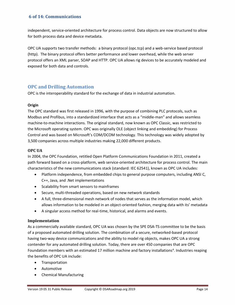
OPC and Drilling Automation OPC is the interoperability standard for the exchange of data in industrial automation.
Origin
The OPC standard was first released in 1996, with the purpose of combining PLC protocols, such as
Modbus and Profibus, into a standardized interface that acts as a “middle-man” and allows seamless
machine-to-machine interactions. The original standard, now known as OPC Classic, was restricted to
the Microsoft operating system. OPC was originally OLE (object linking and embedding) for Process
Control and was based on Microsoft’s COM/DCOM technology. This technology was widely adopted by
3,500 companies across multiple industries making 22,000 different products.
OPC UA
In 2004, the OPC Foundation, retitled Open Platform Communications Foundation in 2011, created a
path forward based on a cross-platform, web service-oriented architecture for process control. The main
characteristics of the new communications stack (standard: IEC 62541), known as OPC UA includes:
• Platform independence, from embedded chips to general purpose computers, including ANSI C,
C++, Java, and .Net implementations
• Scalability from smart sensors to mainframes
• Secure, multi-threaded operations, based on new network standards
• A full, three-dimensional mesh network of nodes that serves as the information model, which
allows information to be modeled in an object-oriented fashion, merging data with its’ metadata
• A singular access method for real-time, historical, and alarms and events.
Implementation
As a commercially available standard, OPC UA was chosen by the SPE DSA-TS committee to be the basis
of a proposed automated drilling solution. The combination of a secure, networked-based protocol
having two-way device communications and the ability to model rig objects, makes OPC UA a strong
contender for any automated drilling solution. Today, there are over 450 companies that are OPC
Foundation members with an estimated 17 million machine and factory installations4. Industries reaping
the benefits of OPC UA include:
• Transportation
• Automotive
• Chemical Manufacturing

6 of 14: Communications
Version 19 05 31 Public Release Copyright © DSARoadmap.org 2019 Page 15
• Energy Monitoring
• Food and Beverage
• Oil & Gas
• Water Treatment
The current technology trend towards the 4th Industrial revolution (German initiative Industry 4.0), leads
to concepts such as platform independence, decentralized intelligent controllers, standardized
communications and security5. OPC UA is well positioned in such a world as applications for the Internet
of Things (IOT) and as base technology for Machine-to-Machine. As an open foundation, the OPC
Foundation is at the nexus of collaboration efforts between a variety of standards organizations and is
heavily involved in the oil industry-based Standards Leadership Council.
OPC UA and Drilling Automation
OPC UA has application across a series of oil field tasks, specifically for drilling and production
monitoring. To integrate with existing oil field and oil company infrastructure and standards, the OPC
Foundation has begun an initiative to allow data servers based on Energistics’ standards (WITSML,
PRODML, RESQML) to interoperate with OPC UA servers. This allows standardization of the flow of data
from field acquisition (via OPC UA) to corporate data storage and application specialists (via
WITSML/PRODML) in a secure fashion.
The tasks accomplished by the WITSML committee include mapping between a WITSML/PRODML
object, such as Well, Wellbore or Log objects, and an OPC UA version of the object. This work entailed
creating a method for automatically browsing a WITSML/PRODML object and generating the OPC UA
information model for that object; this task is the final stages of completion, pending volunteers’ time
and schedule. The information model is in prototype stage and is awaiting a finalized definition of
objects, object types, and data types involved in the mapping.
The committee is defining an OPC UA information model that matches the WITSML/PRODML objects.
The main benefit of this accomplishment is to make the flow and formatting of data both automatic and
invisible to the end user. In addition, real-time data is included in the data flow.
Agents of Change
Internet of Things
The IoT is a growing network of objects, ranging from industrial machines to consumer goods, that can
share information and complete tasks on their own. There is an exponential growth in consumer goods
that do this. For example, refrigerators can now detect milk consumption patterns and order directly
from the grocery store for delivery before the milk runs out. The connected car is now able to integrate
and present information about the nearest gas station as it runs low on fuel and can interact with the
GPS to navigate rapidly to the location.

6 of 14: Communications
Version 19 05 31 Public Release Copyright © DSARoadmap.org 2019 Page 16
This network of objects that can interact and have levels of self-awareness is called the Internet of
Things (IoT). Made up of millions of sensors and devices that generate incessant streams of data, the IoT
can be used to improve drilling automation in many ways. The Internet of Things consists of three main
components:
• Things (or assets) themselves
• Communication networks connecting them
• Computing systems that make use of the data flowing to and from these things.
In Stream capabilities
Traditional analytics must wait until data are persisted in some form of data store. To be run in stream,
analytics need to be embedded as firmware in the control or acquisition system. This places a barrier to
innovation on the data stream by effectively locking out third party agents. Event Stream Processing
(ESP) engines, a subset of complex event processing (CEP) technology, can compute in-memory, in-
stream and in-real time at a millisecond interval. Coupling ESP with real-time subscription
communications systems enables drilling automation to place more complex physics- or data-driven
algorithms into the data stream to solve such issues as:
• Identifying and stopping security breaches
• Predicting and recommending actions to mitigate against mechanical issues
• Determining context and then adding it back into the stream to enrich the flow of information.
Behavioral and pattern-based cyber security
Rule based cyber security solutions are important. However, with an ever-increasingly sophisticated
attacks, cyber security solutions are now being enhanced with behavioral and pattern-based solutions.
These new defense systems can detect hostile activity anywhere on the network through real-time
monitoring of massive amounts of data. Coupled with this powerful analytic technique these defense
systems reveal anomalies and connections that would otherwise be missed. Analytical cyber defenses
can uncover hidden relationships and identify subtle patterns of behavior that may indicate zero-day
and advanced persistent threats, such as low-and-slow attacks, which are much harder to detect
because they happen over time.
Problem Statement A lack of aligned direction on communication strategies across drilling rig systems is hindering the pace
of automation systems innovation. To accelerate development of automation solutions, this lack needs
to be resolved in a consistent and agreed upon manner across the industry.
Barriers The barriers to achieving an open communication system for a fully interoperable drilling automation
system are not technical; they are perceptions of commercial needs. The technical barriers have already
been overcome in industrial automation.

6 of 14: Communications
Version 19 05 31 Public Release Copyright © DSARoadmap.org 2019 Page 17
Proprietary Attitude
Many companies in oil and gas drilling and completion activities believe that proprietary systems block
competitors from entering specific operations. These blocks to participation specifically impact machine
control, machine data, downhole data transmissions systems (telemetry) and prevents access to
information. Some companies claim that access to their control systems encounters liability issues. This
barrier can be overcome through:
• Control of any machine or equipment through the DSA Decision Making and Control Framework
(based on ISA 95) hierarchy will send instruction to the machine; the machine may execute as is
within its proprietary system or may respond that it has certain limitations that the control
system must respect in sending its instructions
• Accessing data from machines and equipment through an understanding that teamwork will
grow the business. Furthermore, operators will specify in contracts the quality of the data, the
calibration and maintenance of the sensors and the requirement to share the data.
Lack of a common standard
The use of proprietary communications systems without a common standard inhibits the progress of
automation. The industry’s willingness to adopt OPC UA for high-rate data and control, combined with
the development of the interface between OPC UA and the commonly used information system of
WITSML will open communications avenues through standard solutions. OPC UA offers significant
advantages in speed, fidelity, metadata and security, which will realize cross company benefits.
Lack of Open Interfaces
The oil and gas drilling and completion industry has progressed in creating interfaces that enable
cooperation between sensor and control companies, and telemetry systems. Gyro while drilling
companies can connect into multiple company mud pulse telemetry systems and the current hard-wired
pipe system encapsulates packages of information from third party sensors and transmits them to the
surface where they are un-encapsulated and decoded. A common standard that enables all transmission
systems between downhole and surface will enable multiple sensor and control loops to manage
aspects of downhole operations.
Way Ahead
Standardized downhole and rig to office telemetry The telemetry of drilling data requires multiple levels of technology. An underlying level of connectivity
must be provided by established information and communications technology, such as TCP/IP
networking on top of satellite, mobile phone or other proprietary connectivity. On top of this there may
also be one or more layers of web technology such as HTTP(S) and/or Web Socket.
With the basic networking established, the industry can implement industry-specific data telemetry
formats based on more specific standards, such as OPC-UA or WITSML/ETP. These provide the
additional items of domain-specific context and metadata that make them useful for real-world
applications, such as drilling automation.

6 of 14: Communications
Version 19 05 31 Public Release Copyright © DSARoadmap.org 2019 Page 18
The implementation stack could look resemble Table 1.
IT Industry Drilling Industry
WebSocket WITSML/ETP
HTTP OPC-UA, WITSML
TCP/IP stack OPC-UA
Satellite, Mobile/Cell Phone network,
Wired Pipe
Proprietary solutions
Table 1
Downhole Telemetry Expected benefits from downhole telemetry include:
• Plug-and-Play for data and services
• Removal of barriers for service provision to enable more companies to compete
• Greater confidence in the reliability, accuracy and meaning of the data provided by enhanced
metadata and context awareness.
Downhole-to-surface telemetry could remain as is using mud pulse telemetry for most operations and
others using hard wired pipe for analysis and testing. Alternatively, hard wired pipe could become a
differentiator on high specification offshore rigs creating a niche environment with very high data rate
capabilities.
Hard wired pipe could be developed into a commodity which enables most rigs across the entire fleet to
offer high data rate capability. Alternative technologies could be developed that provide much higher
data rates and bandwidth than mud pulse without achieving hard-wired pipe capabilities. Such
technologies would predominate and define surface-to-downhole control capability.
Future of downhole telemetry
Hard-wired pipe will be added to high-spec floating rigs and jack up rigs to provide a differentiator to the
potential client. This capability attracts contracts because it provides a real-time conduit for the
operator (the client) to collect downhole wellbore data with the intention to upgrade subsurface models
in real time with an added value from best-decision making in the uncertain exploration and appraisal
environment. Such pipe will also enable advancement of real time surface control on downhole
parameters.

6 of 14: Communications
Version 19 05 31 Public Release Copyright © DSARoadmap.org 2019 Page 19
An alternative lower-cost hard-wired system with pipe retrofit and power transfer abilities will become
available. This system is a first step to commoditized hard-wired telemetry systems and the current
hard-wired pipe OEM will react with accelerated manufacturing efficiencies and reduced pricing that
accelerate adoption. The two competing systems become a win-win in growth of each system.
Mud pulse / EM telemetry will continue to show small advances in bits per second but will not overcome
the latency effect. A new telemetry technology will emerge that offers a higher data rate than mud
pulse and EM with less latency than mud pulse. This system will provide a new opportunity for a reliable
low-cost improved rate and latency system that builds a bridge for additional automation opportunities.
Timeline: five years
Rig-to-Office telemetry using web and WITSML standards is possible today but will mature over the next
five years as the standard is developed to accommodate additional data types and drilling processes.
Standardized downhole-to-surface telemetry is a longer-term goal but can be prototyped on existing
wired-pipe systems. Interim solutions may include BHA to BHA high-speed communication that will
allow BHA tools to communicate with BHA sensors to provide real-time feedback without high-speed
communication to the surface. The proprietary nature of the current wired-pipe systems is a barrier to
standards adoption.
State Based Information One objective of automated drilling will be to endow the system with the ability to operate in
autonomously. A logical “vision” of such a system is drilling on the ocean floor, in which an operator
inputs a location with a target and the system automatically deploys to the location and drills a well to
the target without human intervention.
To reach this state of development, industry must first mechanize the individual tasks that comprise
drilling and add contextual information, so that system has a reference to the current drilling task and
knows what steps will follow. This contextual information must contain the idea of state—where the
program is in the process of drilling. The simplest versions of rig state are rotate drilling, slide drilling,
washing/reaming, tripping in/out or making a connection. By knowing the current rig state, the process
variables can be tweaked to optimize performance, just as in refining and chemical engineering. By
knowing the next or future states, supply chains can also be optimized, minimizing the time spent
between states. State-based contextual information is a pointer to a series of steps in a process. Its main
concern is the current “state” of the environment.
Timeline: Imminent
One requirement of implementing state-based information is a solid knowledge of the individual steps
involved in the process. Attempts at drilling automation, such as Drill-A-Stand, have defined the process
steps, from slips-out to slips-in drilling. As such, rig states as mentioned above can be defined and
implemented to control the set points for each task. One caveat is that rig states have been subject to
proprietary development, which may or may not be consistent with needs of drilling automation rig
states. Additional state-based information will be developed as groups of mechanized tasks are brought

6 of 14: Communications
Version 19 05 31 Public Release Copyright © DSARoadmap.org 2019 Page 20
on-line. The major quality issue will be the consistency of definition, so that the state has
incontrovertible and common meaning.
Operational Intent Contextual information is not limited to the knowledge of state-based context. In almost all cases, the
contextual steps will be modified by external forces, such as economic and natural forces. For instance,
hurricanes or tornados can cause the orderly steps in the drilling process to be interrupted for reasons
of safety. Economic forces, such as contractual obligations (rig is supposed to be at site X by date Y to
prevent losing a lease), can also modify both the sequence of individual tasks as well as the individual
task itself. Operational intent is a modifier to either process or process task.
Timeline: Long term (5+ years)
The current state of focus in drilling automation is on mechanization of individual tasks Although initial
attempts have been made to organize the chain of process steps. Operational intent can only be defined
once both the tasks and the process steps have a non-changing definition and a “standardized” content.
One can only measure deviations from a process if that process is well defined.
Drilling Systems Information Model The most basic issue facing drilling automation is the organization and publishing of drilling data.
Automation can occur without data organization, but it will be proprietary, non-portable, and cost
inefficient. Drilling automation will not develop on a grand scale until it is cost efficient, especially for
low-cost, unconventional objectives. To make drilling automation cost effective, drilling data must be
organized such that common interface or portal can be used by automation algorithms.
The current business model of drilling is a major inhibitor to drilling automation. Third party vendors
interface with the rig data network that supplies operators with drilling data. Variations in
implementation and architecture result in variations in the data content and quality received. In
addition, vendors who are responsible for delivering data (such as MWD/LWD data) may vary from well-
to-well.
The Drilling Systems Information Model (DSIM) is an attempt to organize both drilling process
information and data. It must consider variations in rig construction (different rigs have different sensors
and capabilities) as well as downhole tools and changes that occur to the rig or tools during their
lifetime. Because of these issues, the DSIM is different than WITS0, in that the DSIM defines locations
where similar information can be found and not a specific list of data items. DSIM is intended to provide
a query capability that allow external control and passive model programs able to determine the
rig/downhole tool configuration as well as the available data.
The DSIM also differs from WITSML, in that the data is organized by drill rig and not by the wellbore. The
final key to the DSIM is that each data object has a one-to-one correspondence with a piece of drilling
hardware or drilling process. Each software object models a specific device or process, with the same
root template inherited for each object. Drilling modelling then becomes the summation of the modeled

6 of 14: Communications
Version 19 05 31 Public Release Copyright © DSARoadmap.org 2019 Page 21
parts. When one part of the rig is changed, only the software model for that part changes. If kept in
conjunction with a data historian, then a true record of rig evolution will be kept. Finally, the DSIM will
have the facilities for recording and converting units, as well as asset tracking (i.e, who wrote this piece
of information when).
Concurrently, the DDHub is being mapped. 6 This is described in the Systems Architecture section. It is a
parallel activity to DSIM which, at first sight, appears to be a direct alternate. However, it is thought that
DDHub would overlay DSIM; DDHub would operate at Level 2 on top of the aggregator in the DSA
Decision and Control Framework with DSIM though levels 1 and 2 connecting data sources and machine
controls (see Systems Architecture section.
Timeline: Ongoing (~ 2-5 years)
A first-pass proposal for a DSIM (device based) has been developed and vetted against the data required
to Drill-A-Stand. The fetal data structure is in the process of “standardization” and upon committee
attention will likely be administered by a standards committee (Energistics). From that point, the
industry will determine how and when the DSIM will evolve. If actively supported, the expected time
frame for version 1.0 would be one to two years.
Data Federation One of the challenges the oil and gas industry faces in data management is centered on how to manage
the presentation logic of data. Traditional systems aggregate data into storage based on footprint size or
what appears to be most logical. This presents two challenges. First, not all consumers of data require
the same logical associations across data, and second, physical aggregation of the data in this way is not
agile enough to rapidly adopt new data into the architecture, which leaves some data stranded and
must then be handled by exception. In some cases, this can lead to more than one aggregation solution
being used in the same location (Figure 1).
Figure 1. Simple view of a physical aggregation solution

6 of 14: Communications
Version 19 05 31 Public Release Copyright © DSARoadmap.org 2019 Page 22
This problem can be partially solved using cloud architectures, in which data can simply be stored in its
native format as it is acquired without the need for logical associations. This does not solve the problem
of how to rapidly integrate new data and data that may move location. It also does not answer how to
present data such that it is logical to the consumer application. This is where Data Federation bring real
value to the data architecture (Figure 2).
Figure 2. Cloud based data federation
The underpinning technology of data federation is Representational State Transfer (REST). REST consists
of coordinated constraints that are applied to components, connectors and data elements within a
distributed hypermedia system. The system is then able to ignore the details of component
implementation and protocol syntax to focus on the roles, interaction and interpretation of the
disparate components of the data architecture.
The data federator employs a virtual data layer that understands the location of data and can be
updated as new data appears or existing data moves. The Federation layer virtualizes the data in a
logical hierarchy that can be predefined from both the enterprise level and the consumer level. The
benefit is that the burden of processing and data management is removed from the processing elements
of the system that are using the data. The virtualization layer can also be used to provide common
attributes required across disparate systems, such as the synchronized clocking of data time stamps.
Timeline: imminent through the next 5 years
Data virtualization, federation and cloud technologies that can deliver ‘data lakes’ (large volumes of
stored data) at the rig site in its native format made available for consumption via predefined
virtualization, is available today and is being implemented in other industries. It is expected that this will
become the norm for rig site data aggregation and storage over the coming years.
Multiplexed Communications Multiplexed communications is a technique whereby multiple data streams can be combined into a
single stream. This provides the advantage of being able to send different data at different data rates,
which enables information of higher frequency and importance to be granted greater throughput rates
than those deemed to be less time critical to an operation. The system comprises two units. The MUX,

6 of 14: Communications
Version 19 05 31 Public Release Copyright © DSARoadmap.org 2019 Page 23
which multiplexes the input data into the combined stream, and the DEMUX, which compiles that data
back out to its native format (Figure 3).
Figure 3
Six commonly used methods of multiplexing include:
• Space-division uses different physical communication mediums
• Frequency-division uses different underlying frequencies to modulate signal transmission
• Time-division divides available bandwidth into individual time slots for data transmission
• Polarization-division separates channels based on electromagnetic polarization
• Orbital angular momentum uses electromagnetic radiation, may be combined with the physical
methods above and can achieve data rates up to 2.5Tbs
• Code-division uses multiple data sources broadcast data simultaneously on the same frequency
allowing the system to implement several frequency bands to transmit multiple data sources at
differing rates.
Implementation built on top of multiplexing technologies are already beginning to make their way into
industrial applications, such as Time Triggered Gigabyte Ethernet. In this scenario communication is time
spliced in a synchronous solution such that the same information can be transmitted between devices
on multiple physical connections and thus provide secure and synchronous communications with built in
physical redundancy.
Timeline: Imminent
Although these technologies are available for implementation today, we also see some significant leaps
in combinations of multiplexing and time sliced redundant communications medium over the next 4 to 5
years.
Self-Aware Devices - IOT Spectacular advances in technology have introduced increasingly complex and large-scale computer and
communication systems. Autonomic computing has been proposed as a grand challenge that will allow
systems to self-manage this complexity using high-level objectives and policies defined by humans. IoT
will exponentially increase the scale and the complexity of existing computing and communication
systems; autonomy is thus imperative property for IoT systems.

6 of 14: Communications
Version 19 05 31 Public Release Copyright © DSARoadmap.org 2019 Page 24
One of the key tenets of the IOT is the ability for devices within the systems to be able to share
information while continuing their primary task (measurement, control, advice etc.). This fundamentally
changes the architecture of the system from a sequential and centralized system to one of pluralities
decentralized information flow. In this scenario, it is imperative that the communications solution be
able provide not just the connectivity but the synchronous elements of data movement. This ties very
well with the multiplexing section noted above and technologies such as TTGB.
Timeline: Imminent
Timing of the introduction of IOT will undoubtedly be osmotic in nature. It is likely that IOT devices will
gradually appear on the rig and their self-aware capabilities will be phased in piecemeal as the system of
systems grows. For this reason, introduction has already begun, but the IOT inferred value will gradually
appear over the following 4-5 years,
Specific KPIs might include:
• Security: tightly integrated hardware and software security from the edge to the cloud, along
with data protection and policy management, delivers trusted data to automation systems that
deliver value to end users
• Interoperability: modular, standardized technologies seamlessly communicate to one another,
accelerating automation and reducing the cost of deploying and maintaining complex IoT
solutions
• Manageability: device, security, and advanced data management provide end users with the
capabilities to easily manage large-scale IoT systems built from multiple venders products and
services
• Analytics: delivering trusted data and the capability to run analytics near the sensors and
streaming the results along with raw data to the cloud enabling real-time insights and
streamlining operations.
Future Data Values and Data Enriched The communication of information at the rig site will develop beyond sensor measurements at specified
horizons, such as depth and time. In addition, many companies are also now including the ability to
predict or project future states of the system. Data historian vendors, such as OSISoft, have already
begun rolling out next generation data solutions that include projected or future values associated with
specific sensor or device values at any horizon. An example of how this would look in a drilling
automation system is a communication stream that provides the current Inclination of the drill bit as
well as the expected inclination in 3 feet based on a predictive algorithm.
Timeline: Imminent
Although the technology exists to do the necessary predictive or projected calculations for DSA today,
the communications structures to transmit this information associated with current values is only now
being released to the market. It may be a year before this capability begins to take hold on the drilling

6 of 14: Communications
Version 19 05 31 Public Release Copyright © DSARoadmap.org 2019 Page 25
system, with the initial roll out of these solutions likely to be downstream in pipeline integrity and
refinery operations first.
Cyber Information The primary objective of DSA-R Communications cybersecurity is to ensure that a rig survives a cyber-
event without loss of function in critical applications.
Manufacturers, developers, integrators, information and operational technology staffs face the
challenge of providing cybersecurity for very different technologies, architectures and data types (IT vs.
IACS). Sourcing, transmitting and storing data in highly connected computer environments demands
new approaches to cybersecurity.
Requests and requirements for broadband connectivity to critical systems will arguably continue to
increase, making the routing of control system data over non-control networks a common and expected
practice. This desire for more information sharing has led to increased cybersecurity risks inherent in
more open and more connected networks (SCADA).
The most obvious risk is the possibility of connections to unprotected networks (IoT). But in practice,
vulnerabilities exist within all system architecture layers, from the user interfaces to the applications and
into the data storage and presentation functions. Even when security controls and embedded security
features protect these system layers, malicious or careless introduction of unauthorized software into
the control system domain is relatively straightforward.
The future state of controls and data security in drilling automation systems—the Rig of Things or RoT—
is ultimately a safety issue and relies on hardware and software architectures that provide seamless
connectivity while maintaining and protecting as-designed functional performance. The practice of
proving security for user interfaces, evolving applications and sensitive data, while simultaneously
providing defined communication services and responding to cyber threats, will be increasingly
automated and transparent to integrated control systems.
Emerging security systems will mine and analyze combinations of already-available data and monitor
network behavior patterns to expose and neutralize risky connections and harmful software functions.
Data communications will evolve from unprotected protocols having no inherent security, to purpose-
built protocols that incorporate security structures that discern and respond to anomalous behavior
within the protected network and connected devices. Network devices will become context-aware, take
advantage of protocols that include security handles or tags by default and automatically reconfigure as
needed, without human intervention. Compensating controls will be developed and implemented for
legacy systems without disrupting the useful mission of the communicated data itself. Inherent to
automatically re-configuring security systems is the historically troublesome impact of self-reconfiguring
software on highly integrated systems. But, by paying attention to quality engineering programs,
developers can overcome these potentially blocking problems.

6 of 14: Communications
Version 19 05 31 Public Release Copyright © DSARoadmap.org 2019 Page 26
Key elements for providing security for emerging on-asset control systems include but are not limited to:
• Clear security policy and rigorous policy execution
• Sensing communications protocols that are context-aware and resilient
• Sensing and communicating field devices that are context-aware and resilient
• Federated, authenticated identities for communicating on-asset devices and endpoints
(assumes agreement that all data communications must be protected)
• Federated, authenticated identities for communicating remote devices and endpoints (assumes
agreement that all data communications must be protected)
• Automated vulnerability prediction, detection and patching between and within system
architecture layers
• Automated security intrusion sensing, monitoring, remediation and contingency capability
• Definition and arbitration of data ownership
• Metadata (or descriptors) collection, storage and analysis capability.
The way ahead will rely heavily on reliable human and machine identity enrollment and on
authentication practices, disciplined software engineering practices, ubiquitous on-asset sensing and
communicating technologies, “future-friendly” equipment design and disciplined system support
behavior by personnel who interact with critical offshore control systems.
Timeline: Immediate
Given the nature and growing prevalence of cyber threats, it is assumed that the elements listed above
will be implemented onto communication protocols as a priority over the next 1 to 2 years.
Cyber Security Key aspects included under the heading of Cyber Security include:
• Secure communication (remote, internally, etc.)
• Integrity of data, communication, software, etc.
• Availability of services, data, communication, software, etc.
• Confidentiality of data, services and communications.
The solutions and actions required to address Cyber Security concerns fits nicely with part of the MODU
cybersecurity framework profile that United States Coast Guard (USCG) is developing together with
NIST, NCCoE, IADC and other industry interest groups. Current state is defining the core mission
objectives for a MODU and mapping cybersecurity to these core missions. IADC guidelines currently
under development include minimum cybersecurity requirements, hardening, network segmentation
and situational awareness, and monitoring guidelines.
Managing cyber risks is a critical success factor for drilling automation. Cyber risk management, or
cybersecurity, is the process of protecting information, systems, services and communications by
preventing, detecting, and responding to cyber-attacks (appendix 1). Cybersecurity encompasses
protection against malicious and non-malicious, inside and outside actors to maintain the operational
integrity of the drilling process.

6 of 14: Communications
Version 19 05 31 Public Release Copyright © DSARoadmap.org 2019 Page 27
Part of the roadmap is to develop a cybersecurity program for drilling automation that are based on:
• NIST Cybersecurity Framework for Improving Critical Infrastructure Cybersecurity
• ISA/IEC 62443 Series of Standards on Industrial Automation and Control Systems (IACS) Security
• IADC Guidelines for Assessing and Managing Cybersecurity Risks to Drilling Assets and other
IADC cybersecurity guidelines
• MODU Cybersecurity Framework Profile
The IADC/API draft cyber security management plan is attached as Appendix I.
References 1. Pink T, Cuku D, Pink S, Chittoor V, Goins A, Facker B and Hanford R: World First Closed Loop Downhole Automation Combined
with Process Automation System Provides Integrated Drilling Automation in the Permian Basin, paper SPE 184694, presented at
the SPE/IADC Drilling Conference and Exhibition, The Hague, The Netherlands, March 16–17, 2017.
2. Macpherson J, Roders I, Schoenborn K, Mieting R and Lopez, F: Smart Wired Pipe: Drilling Field Trials, paper SPE 194095,
presented at the SPE/IADC Drilling Conference and Exhibition, The Hague, The Netherlands March 17–19, 2019.
3. https://www.energistics.org/portfolio/witsml-data-standards/
4. https://opcfoundation.org
5. Klitou D, Conrads J, Rasmussen M, Probst L, Pedersen B: Germany Industrie 4.0, Digital Transformation Monitor, January
2017. https://ec.europa.eu/growth/tools-databases/dem/monitor/sites/default/files/DTM_Industrie%204.0.pdf
6. Cayeux E, Daireaux B, Saadallah N and Alyaev S: Toward Seamless Interoperability Between Real-Time Drilling Management
and Control Applications, paper SPE 194110, presented at the SPE/IADC Drilling Conference and Exhibition, The Hague, The
Netherlands March 17–19, 2019.

6 of 14: Communications
Version 19 05 31 Public Release Copyright © DSARoadmap.org 2019 Page 28
Appendix I – IADC API Cyber Risk Management Plan

6 of 14: Communications
Version 19 05 31 Public Release Copyright © DSARoadmap.org 2019 Page 29