Communication Option Information - Stewart Signs
15
Communication Option Information 1.800.237.3928 stewartsigns.com Chapter 3 Rev1802
Transcript of Communication Option Information - Stewart Signs

Communication Option Information
1.800.237.3928stewartsigns.com
Chapter 3
Rev1802

Intentionally Left Blank
Chapter 3 | Communication Option Information

1
Communications Options Summary
Choosing a communications method for uploading content your LED sign is critical. Stewart Signs offers communications options and methods that are customized based on the customers’ needs. Here is an overview of the different configurations available along with information about the benefits for each application to help you, our customers find a method that is suited to your needs.
Communication Type
Wired Communication Options330 ft 1,000 MB/s
900 ft 500 MB/s
Ethernet
Ethernet Extender
Range Speed
Table #3.1
Wireless Communication Options Range Speed100 MB/s1,500 ftShort Range Wireless
No Limit 500 MB/sLong Range Wireless
Chapter 3 | Communication Option Information

2
Flow chart to determine best communication method to use.
Table #3.2
Chapter 3 | Communication Option Information

3
Ethernet
Features:An Ethernet connection provides a fast and reliable communication to upload content to a Stewart sign.
Cat 5e cable or better is installed in a dedicated 1 ½ inch conduit.
Ethernet is a wired communication method allowing an Ethernet communication card (installed on your computer or your network) to communicate with the LED display over a Local Area Network (LAN). When properly deployed, Ethernet can communicate up to 330ft with data transfer speeds up to 1GB/s (1,000MB/Sec).
Benefits:
Cost Effective No Additional CostReliability Fewer components are needed to connect the sign to a network. Thus
there are fewer potential points of failure. Simplicity Installation of Ethernet is easier, typically, and less expensive than other
communication options. Efficient Ethernet consumes less power than other communication options, for
those who have a laptop or like to conserve energy.Performance Ethernet offers a fast data connection to the sign.
Distance: Maximum cable length of 330 feet.
Disadvantages:Distance - Maximum cable length is 330 feet; refer to the Ethernet extender solution when cable length exceeds 330 feet.
Considerations:Distance from the LED sign to the Computer or Network switch is less than 330 feet for a Cat 5e cable or better. An Ethernet cable can NOT be run in the same conduit as power lines.
Wired Communication Options
Figure #3.1
Chapter 3 | Communication Option Information

4
Requires:Outdoor Cat 5e Cable or better: Such as Belden 7919A or Belden 1594A.
Separation of electrical and Ethernet cables by a minimum distance of 12 inches (National Electric Code, NEC, 300.5(A))
Ethernet Extender
Features:An Ethernet extender forwards information between connected devices over distances that exceed the limitations of a standard
Ethernet connection to upload content to the sign.
One device, an Ethernet extender receiver, with the patch, cable is factory installed in the sign. Another Ethernet extender, with a patch cable, will be installed onto the network. In ideal conditions, an Ethernet extender can communicate up to 900ft with data transfer speeds up to500MB/Sec.
Benefits:Extended range beyond Ethernets inherent distance limitations of 330 ft. out to 900ft.
Distance:Maximum cable length of 900 feet.
Disadvantages:Additional devices are required.
Considerations:One device, a media converter, with the patch cable is factory installed in the sign. The installer will connect another media converter inside the building onto the network. An extended Ethernet cable can NOT be run in the same conduit as power lines.
Requires:
• Outdoor Grade Cat 5e Cable or better: Such as Belden 7919A or Belden 1594A.• Separation of electrical and Ethernet cables by a minimum distance of 12 inches (National
Electric Code, NEC, 300.5(A)).
Figure #3.2
Chapter 3 | Communication Option Information

5
Used for the following Communication Methods:
• Ethernet
o Direct Data Cableo Network Data Cable
• Ethernet Extender
o Direct Data Cableo Network Data Cable
Both of the above communication methods utilize Cat 5e cables or better.
The approved process for joining two Cat 5e or better data cables for a sign is to splice them together using moisture resistant gel-filled connectors.
Instructions:1. Open access panel and locate the Cat 5e or better cable in the leg of the sign. See Figure
#3.3. Note: Typically one leg contains the electrical lines and the other leg contains thedata.
2. Pull the Cat 5e or better cable down from the sign and out through the access point on thesign.
3. Cut the RJ45 connector from the end of both Cat 5e or better cables. Always splice, do notuse RJ45 connectors to make this connection.
4. Pull the Cat 5e or better cable coming from the building up and out through the accesspoint on the sign. Connect
5. Make the connections see Figure #3.4 and 3.5, using moisture resistant Gel-filled connectorsfrom manufactures such as 3M (Scotchlok™ connectors) or REGAL (JD-UR connectors).These connectors can be purchased at most home improvement centers. See Figure #3.6.
6. Push the completed connected cable back into the sign leg and replace the access cover.
Chapter 3 | Communication Option Information
6
Figure #3.3
Figure #3.6
Cable from LED
Cable fromBuilding
Figure #3.5
Figure #3.4
Chapter 3 | Communication Option Information
7
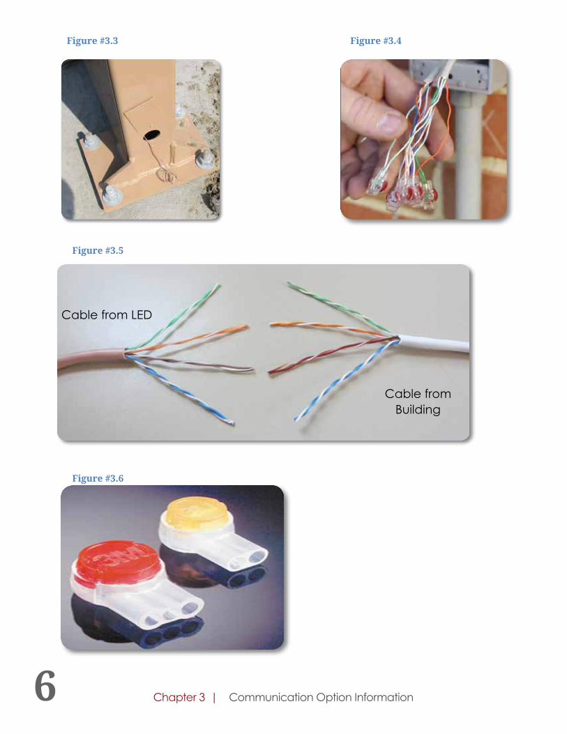
Features:Short range wireless consists of two radio transceivers. Both radios transmit and receive messages between the sign and the computer(s) through radio frequencies (IEEE 802.11, N). Even when a local area network does not exist, the result of wirelessly connecting the sign to a single computer creates a network of two devices; between the sign and the computer. When connecting to an existing local area network, the short range wireless connects to the customer’s network hub which allows access to the sign by other computers on the network.
One device, the sign radio, with the patch cable is factory installed in the sign. The speed of the network is very good and is suitable to send video and picture files to the sign. In ideal conditions, high-security local wireless can communicate with data transfer speeds up to 100MB/s.
Benefits:Installation Cost Savings – When direct wire cable methods cannot be used due to high installation costs.
Distance:Up to 1,500 feet, under line-of-sight conditions.
Disadvantages:Limit to distance. - Direct line-of-sight between antennas provides a higher potential for stable connectivity. This industrial quality short range wireless has proven to work without direct line-of-sight at ranges of 200 – 400 feet. Connectivity may ultimately require direct line-of sight between antennas in some instances. RF may use unlicensed public channels which have numerous causes of interference.
Wall or Pole Mounting Kit (Included)
External Omni Antenna (Included)
Weatherproof Casing
Wireless Communication Options
Short Range Wireless (High-Security Local Wireless)
Figure #3.7
Chapter 3 | Communication Option Information
8
Relocating antennas or installing more powerful, higher gain antennas may be needed when interference occurs. Antennas are not guaranteed to solve interference problems and the customer is responsible for the cost and installing or relocating devices.
Considerations:The distance for the device is limited to 1,500 feet or less and the building radio must be located outside the building to be effective. Wi-Fi is very susceptible to interference, and even in “ideal” conditions, dozens or even thousands of transmission and receive errors occur every hour. This rate will increase exponentially as you add more devices and when other access points are added nearby. Wi-Fi can be interrupted by microwave ovens, cordless phones, and other devices that operate near the 2.4 GHz (or 5 GHz) range. The signs external antenna is shipped with the sign, to be installed on the outside of the sign at the time of installation.
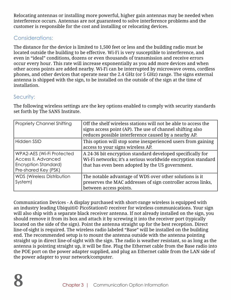
Security:The following wireless settings are the key options enabled to comply with security standards set forth by The SANS Institute.
Propriety Channel Shifting Off the shelf wireless stations will not be able to access the signs access point (AP). The use of channel shifting also reduces possible interference caused by a nearby AP.
Hidden SSID This option will stop some inexperienced users from gaining access to your signs wireless AP.
WPA2-AES (Wi-Fi Protected Access II, Advanced Encryption Standard)Pre-shared Key (PSK)
A 24-36 bit encryption standard developed specifically for Wi-Fi networks; it’s a serious worldwide encryption standard that has even been adopted by the US government.
WDS (Wireless Distribution System)
The notable advantage of WDS over other solutions is it preserves the MAC addresses of sign controller across links, between access points.
Communication Devices - A display purchased with short-range wireless is equipped with an industry leading Ubiquiti© PicoStation© receiver for wireless communications. Your sign will also ship with a separate black receiver antenna. If not already installed on the sign, you should remove it from its box and attach it by screwing it into the receiver port (typically located on the side of the sign). Point the antenna straight up for the best reception. Direct line-of-sight is required. The wireless radio labeled “Base” will be installed on the building end. The recommended setup is to mount the antenna outside with the antenna pointing straight up in direct line-of-sight with the sign. The radio is weather resistant, so as long as the antenna is pointing straight up, it will be fine. Plug the Ethernet cable from the Base radio into the POE port on the power adapter supplied, and plug an Ethernet cable from the LAN side of the power adapter to your network/computer.
Chapter 3 | Communication Option Information

9
Features:Long Range Wireless provides a fast, secure Internet connection through a 4G LTE cellular modem to upload content to the LED sign. Sign uploads are quick and easy with standard data plans with speeds up to 100 MB/s.
Benefits:
Simplified Sign Management Easy to network and control several signs from a single computer.
Installation Cost savings when direct wire cable methods cannot be used due to high installation costs.
Remote Programing The ability to add content to the LED sign from many different Windows computers over the Internet.
Distance:Unlimited.
Considerations:The customer will need to activate a new Wireless Data Plan. Displays outside of the Verizon Wireless 4G LTE coverage area or with more than 80,000 pixels are required to arrange for Wireless Data Plan with your provider. See the Coverage Map to verify coverage in your area https://vzwmap.verizonwireless.com/dotcom/coveragelocator.
The default IP address of the sign controller is 192.168.111.100 unless specifically requested differently when ordered. You may need to change your IP address range to match this IP range to see the sign.
At this point, the wireless radio should have some lights on it. You are specifically looking for at least an amber signal strength light. If you do not, please verify that the sign is on, the radio is in direct line of sight, and the radios are within the recommended distance from each other (1500 feet).
If they are within recommended distance and you are still not getting any signal strength, verify there are no obstructions for the radios (both physical and electrical).
If there is still no signal, please contact our technician support.
Long Range Wireless Broadband Wireless4G LTE Cellular Data Only
Figure #3.8
Chapter 3 | Communication Option Information

10
Stewart Signs Cell Data PlanStewart Signs has an all-inclusive cost management solution with a 5-year data plan service option.
The Cell Connect option from Stewart Signs means reliable communication through Verizon Wireless’ extensive 4G LTE coverage area. With no antennas to align, no IP addresses to network, and no software to download, a cellular connection is a distinct advantage for a smooth experience.
An internet connection also means that our signs can remotely diagnose and help resolve many issues that may arise. Our software is cloud-based and we manage the network communications process, meaning once power is connected to the sign, you’re DONE!
The process is simple:
1. Verify that there is cell coverage at the location of sign install. You can checkcoverage here: https://vzwmap.verizonwireless.com/dotcom/coveragelocator/.
2. Configure the sign with LEDCOM-WDME-KIT: Stewart Signs supplied service,“Wireless Data Modem (Stewart Signs svc)”.
3. Complete the required paperwork.
4. A signed quote form must be submitted with the order(s).
5. By signing the quote form, you, the customer, affirm and agree to the terms andconditions listed at: https://www.signcommand.com/data-plan/.
6. The Data Plan will be listed on the quote form.
Wireless Data Plan
To activate a Wireless Data Plan with a third party carrier (Verizon, AT&T, or Sprint). The carrier will then provide the customer with an MTN (Mobile Telephone Number) and a Static IP address which the customer will have to send in for full testing before shipping (see Stewart Signs Cell Modem Form on next page).
Procedures for Processing Orders with a Wireless Data Modem:
1. Stewart Signs purchasing will submit an ESN request with part:
a. Order Part Number: LEDCOM-LRW-KIT.
2. The manufacturing will return an Electronic Serial Number, ESN, to Stewart Signs.
with your Third Party provider
Chapter 3 | Communication Option Information

11
3. The ESN is provided to the customer:
a. The customer gives this number to their wireless provider (Verizon, AT&T orSprint) when setting up their service.
4. The customer requests their wireless provider to activate a new data line using theprovided ESN:
a. Our suggestion is to start with a 1Gb monthly data plan.
b. Monitor and adjust as needed but it is less expensive to have more than neededuntil history is developed.
For DayStar Media Users ONLY:
5. The customer needs to request a Static IP Address for the Wireless Data Modem fromthe wireless provider. Wireless providers typically charge $500 for a static IP address
6. The wireless provider will then give the customer the following information:
a. The MTN (Mobile Telephone Number).
b. Static IP Address.
7. The customer is required to return the MTN and Static IP Address to Stewart Signs.
8. This allows Stewart Signs to activate the modem for complete testing before shippingthe LED display.
Chapter 3 | Communication Option Information

12 Chapter 3 | Communication Option Information
EBSCO Sign Group, 1400 8th Street North, Clanton AL, 35045 |1-800-237-3928
FCC NoticeAll components have been tested and found to comply with the limits for a Class A digital device, pursuant to part 15 of the FCC Rules. These limits are designed to provide reasonable protection against harmful interference when the equipment is operated in a commercial environment. This equipment generates, uses, and can radiate radio frequency energy and, if not installed and used in accordance with the instruction manual, may cause harmful interference to radio communications. Operation of this device is subject to the following two conditions: (1) This device may not cause harmful interference, and (2) this device must accept any interference received, including interference that may cause undesired operation. The user is cautioned that any changes or modifications not expressly approved by the party responsible for FCC compliance could void the user’s authority to operate the equipment.Each sign will contain one of the following LED modules:
LED-10M-RGB-32X32P-320X320M, LED-16M-RGB-20X20P-320X320M, LED-20M-1RGB-16X16P-320X320M, LED-20M-1RGB-8x16P-160X320M, LED-20M-2R-8X16P-160X320M, LEDDM-10M-1RGB-32X32P-320X320M, LEDDM-10M-1RGB-32X32P-320X320M-2017, LEDDM-16M-2RGB-20X20P-320X320M, LEDDM-16M-2RGB-20X20P-320X320M-2017, LEDDM-20M-2RGB-16X16P-320X320M, LEDDM-20M-16X16P-320X320M-2017
Power Supply:Meanwell RSP-320-5
Send Card:SENDCARD-NS
Receive Card:RECCARD-MRV560-NS
Control SystemIndustrial PC - Lanner HQ-LEC-7020D V1.TS128MSQ64V8U GB DDR2 (FCC certified)
Wireless Radios and Modems (If ordered):Ubiquiti BulletM2HP with POE 24v (FCC Certified)Sierra Wireless Airlink LS300 (FCC Certified) Sierra Wireless R5-S1-10 RV-50 (FCC Certified)

13
Notes:
Chapter 3 | Communication Option Information