
Communication Industrial Standard of PRC - DigiKey
29
Communication Industrial Standard of PRC YD/T 1591-2006 Technical Requirement and Test Method of Charger and Interface for Mobile Telecommunication Terminal Equipment Published by Dec 14, 2006 implemented by Dec 14, 2006 Published by Ministry of Information and Industry of PRC
Transcript of Communication Industrial Standard of PRC - DigiKey

Communication Industrial Standard of PRC
YD/T 1591-2006
Technical Requirement and Test Method of
Charger and Interface for Mobile
Telecommunication Terminal Equipment
Published by Dec 14, 2006 implemented by Dec 14, 2006
Published by Ministry of Information and Industry of PRC

YD/T 1591-2006
I
Table of contents
Foreword ............................................................................................................................................... Ⅱ
Introduction.......................................................................................................................................... Ⅲ
1 Scope..............................................................................................................................................1
2 Specification reference document ..................................................................................................1
3 Definition and abbreviation............................................................................................................2
4 Technical requirement ....................................................................................................................3
5 Test method ..................................................................................................................................14
References ..............................................................................................................................................

YD/T 1591-2006
II
Foreword
This standard is prepared referring to the following standards:
1. GB4943-2001 Security of Information Technical Equipment
2. YD 1268.2-2003 Security Requirement and Test Method of Lithium Battery Charger for the
Mobile Communication Terminal
3. GB9254 Wireless Interference Limit and Measure Method of Information Technical Equipment
4. GB17465.1 Housing and Similar Appliance Coupler Part I: Universal Requirement
5. GB 17625.1 Magnetic Compatibility Limit Emission Limit for Harmonic Current
6. GB 17625.2 Magnetic Compatibility Limit Limit for the Voltage Fluctuation Generated by
the Equipment with the Rated Current Less than 16A in the Low-Voltage Supply System.
When the charger simultaneously works with the mobile communication terminal, its magnetic
compatibility feature should respectively meet the magnetic compatibility requirement of the
mobile communication terminal in different modes. Meanwhile, during the preparing process of
the standard, it also refers to the electric feature and mechanical structure of “universal serial bus
specification (version 2.0)” interface.
With the development of the technology, the related standards will be continually prepared. After
this standard is issued, we will conduct researches on the technical requirement and test methods
of the equipment such as on-board DC charger and plan to supplement the corresponding parts
as the supplementary documents of this standard if necessary.
This standard is proposed and managed by China Communication Standardization association.
Drafted by: Telecom Research Institute of Ministry of Information and Industry
Konka Group Co., Ltd
Key drafters: Liu Jun, Men Meng, Yuan Weijun, Yuan Yuan, Zhang Xia, He Guili, Li Hongtao,
Du Yong

YD/T 1591-2006
III
Introduction
This standard is prepared to guarantee the security of the product and availability, meanwhile, it
enables the mobile communication terminals with different types to use the charger having the same
specification to reduce the electronic waste, protect the environment, save resource and reduce the
use cost of the mobile communication terminal through the uniform interface mode and technical
requirement.
Considering the requirement for the data exchange between the mobile communication terminal and
peripheral equipment and sharing possibility of the charging cable, this standard refers to the A series
interface specification of the Universal Serial Bus (USB) to improve the application efficiency and
convenience of the related components.
Considering the individual development of the mobile communication terminal, this standard
regulates the uniform connection interface and sets it on the charger side, and the connection
interface on the mobile communication terminal side is identified by the designer and manufacturer
of the products.

YD/T 1591-2006
1
Technical Requirement and Test Method of Charger and Interface for
The Mobile Communication Terminal
1 Scope
This standard regulates the technical requirement and test method of charger and interface of
the mobile communication terminal (hereafter called as the “terminal”), including the physical
feature, electric feature, security feature, magnetic compatibility and environment adaptability
of the AC charger and interface.
This standard is applicable to the interface of the terminal charger, AC charger and connection
cable.
2 Specification reference document
The articles in the following document become the articles of this standard through the
reference of this reference. For any reference document with the date, its subsequent modified
contents (not including corrected content) or revisal versions are not applicable to this
standard, however, it is encouraged that all parties reaching this agreement on this standard
study whether the latest versions of these documents can be used. For any reference files
without the date, its latest version is not applicable to this standard.
GB 2099.1-1996 Housing and Similar Plug and Socket Part I: Universal Requirement
GB 4943-2001 Security of Information Technical Equipment
GB 5023.5-1997 Insulation Cable Polythene below the Rated Voltage 450/750V Part V:
Software Cable (chord)
GB9254 Wireless Interference Limit and Measure Method of the Information
Technology Equipment
GB 17465.1-1998 Housing and Similar Appliance Coupler Part I Universal Requirement
GB 17625.1 Magnetic compatibility Limit Emission Limit for Harmonic Wave
Current
GB 17625.2 Magnetic compatibility Limit Limit for the Voltage Fluctuation and
Flickering Generated by the Equipment with the Rated Current less than
16A in the Low-Voltage Supply System
GB/T 17626.2 Magnetic Compatibility Test and Measure Technology
Anti-Interference Test for Static Discharging
GB/T 17626.4 Magnetic Compatibility Test and Measure Technology
Anti-Interference Test for Electric Quick and Instantaneous Pulse Cluster
GB/T 17626.5 Magnetic Compatibility Test and Measure Technology Surge (impact)
Anti-Interference Test
YD 1268.2-2003 Security Requirement and Test Method of the Lithium Charger for the
Mobile Communication Terminal

YD/T 1591-2006
2
ISO 7637-2:2004 Vehicle Electric Interference of Conduction and Coupling Part II:
Instantaneous Conduction along the Line
3 Definitions and abbreviations
The following definitions and abbreviation are proper for the standard.
3.1 Definition
3.1.1 Connection plug
The connection cable terminal and connection plug with the charger
3.1.2 Connection socket-outlet
The socket of the charger with the connection cable
3.1.3 Direct plug-in charger
The AC power plug and shell of the charger are composed of a whole and its weight is
supported by the socket on the wall.
3.1.4 Class II equipment
The shock-resistance not only protects the basic insulation, but also adopts the equipment
with the attached security protection measure. This type of equipment does not depend on
the protection grounding and protection measure of the installation environment.
3.1.5 Class V-0 material
Tested by the GB 4943-2001 appendix A, this material can combust or scorch, but the
average duration does not exceed 5s, the released scorching particle or combustion drop
upon combustion does not lead to the combustion of the absorbent cotton.
3.1.6 Class V-1 material
Tested by the GB 4943-2001 appendix A, this material can combust or scorch, but the
average duration does not exceed 25s, the released scorching particle or combustion drop
upon combustion does not lead to the combustion of the absorbent cotton.
3.1.7 Connection mode with AC power
3.1.7.1 Detachable power supply cord
The cord using the proper appliance connection to connect with the charger and used for
power supply
3.1.7.2 Non-detachable power supply cord
The cord fixed on the charger or installed with the charger for power supply
3.1.7.3 The side of mobile telecommunication terminal
Generally it indicates the mobile communication terminal connection cable and plug
connected to the DC output plug of the charger
3.1.7.4 The side of charger
Generally it indicates the plug connecting with the charger and DC output.
3.2 Abbreviation
USB universal serial bus
PVC polyvinyl chloride
VBus voltage bus
GND ground
AWG American wire gauge
STC stranded Tin copper

YD/T 1591-2006
3
4 Technical requirement
4.1 Connection structure
The interface of the terminal and charger involved in this standard is set on the charger side
and is defined by the mechanical fitting between the plug and socket and electric
performance; the charger is connected to the terminal on another side through the connection
cable to realize the charger function. The interface between the terminal and connection
cable is designed by the designer, as shown in the figure 1 and figure 2.
Figure 1 Illustration I for connection structure
Figure 2 Illustration II for connection structure
4.2 Connection interface
4.2.1 Mechanical structure of the connection interface
The connection interface adopts the connection plug and socket of the universal serial bus
interface shown in the figure 3 and figure 4 (refer to USB A series).
Designed by the designer
Charger side
Connector socket
(refer to USB A series)
Connector socket (refer to USB A series)
Side of the mobile communication terminal
Charger side
Charger
Mobile com
munication
terminal
Connector socket (refer to USB A series)
Connector socket (refer to USB A series)
Side of the mobile communication terminal
Designed by the designer

YD/T 1591-2006
4
Figure 3 Structure and size of the connection plug (USA A series)
Printed circuitboard
Contact
Contact of the socket
(typical value)
(typical value)
Central line
Note:
1) All sizes use the mm as the unit.
2) For the surface and plug of the socket, the
allowed minimum space between the
protection cover of secondary plastic
injection forming is 2.67 mm.

YD/T 1591-2006
5
Figure 4 Structure and size of the connection plug (refer to USB A series) II
4.2.2 Reliability requirement of the connection interface
4.2.2.1 Insertion force and pulling force
The plugging is allowed between the plug and socket, when the speed of the plug does
not exceed 12.5 mm/min, maximum force for inserting fully the plug into the socket can
not exceed 35N and the required force for pulling the plug from the socket can not be less
than 10N.
4.2.2.2 Plug lifetime
Plug in/plug out for 15000 periods at the maximum speed during the 200 periods of one
hour, after the plugging ends, the mechanical structure should not be damaged. The
required minimum force for pulling the connection plug out from the socket is not less
than 8N, the electric performance should meet the requirement in the 4.2.3.
4.2.3 Electric performance of the connection interface
4.2.3.1 Electric performance requirement of the connection interface on the terminal side
(1) The DC input voltage of the terminal charging interface is 5V(1±5%): maximum
Contact of the plug
Central line
typical valuetypical value
typical value
UL94-VO plug external cover
Protection cover of once plastic injection
Central
line
typical value
Note: 1) All sizes use the mm as the unit. 2) The total length of the connector and cable
component is the distance from base point of the A series plug to the base point of the B series plug or to rough terminal.
Protection cover of once plasticinjection forming
Gold-plating area
YD/T 1591-2006
6
absorption current is 1800mA. Regardless of the input power of the charger, the
charging control circuit on the terminal side should be securely charged according
to self requirement and the phenomena such as the over heating, combustion,
explosion and other circuit damage should not occur.
(2) The charging control circuit on the terminal side should include the voltage limit
protection set. when the charging interface of the terminal is imported by over 6V
voltage, if the secure charging can not be guaranteed, the charging control circuit
on the terminal side should securely charge according to self requirement, the
phenomena such as the over heating, combustion, explosion and other circuit
damage should not occur.
(3) When the connecting power supply set is not standard regulated charger (such as
the built-in USB A series interface of the computer or portable computer).
(4) Considering that absorption current’s security to the power supply set when the
terminal is charging which has been produced and sold before this standard is
implemented, the designer should carefully consider whether the sold terminals
meet the secure charging measure regulated in the standard, when this standard is
adopted, the physical design of the interface between the terminal and connection
cable different from old design should be used, or the connection cable should be
installed by the recognition and current limit set to prevent the user from risk
generated upon mistaken operation.
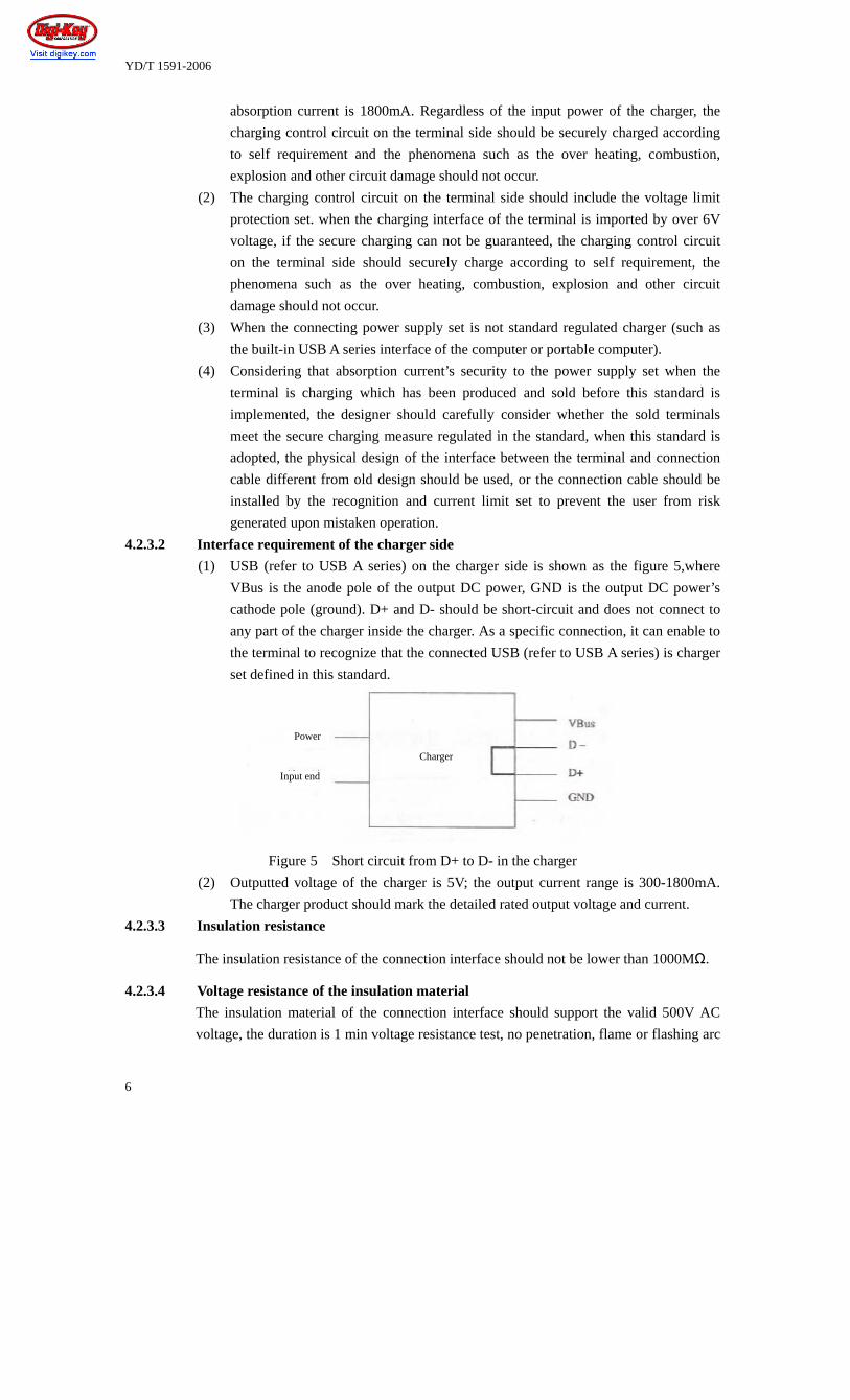
4.2.3.2 Interface requirement of the charger side
(1) USB (refer to USB A series) on the charger side is shown as the figure 5,where
VBus is the anode pole of the output DC power, GND is the output DC power’s
cathode pole (ground). D+ and D- should be short-circuit and does not connect to
any part of the charger inside the charger. As a specific connection, it can enable to
the terminal to recognize that the connected USB (refer to USB A series) is charger
set defined in this standard.
Figure 5 Short circuit from D+ to D- in the charger
(2) Outputted voltage of the charger is 5V; the output current range is 300-1800mA.
The charger product should mark the detailed rated output voltage and current.
4.2.3.3 Insulation resistance
The insulation resistance of the connection interface should not be lower than 1000MΩ.
4.2.3.4 Voltage resistance of the insulation material
The insulation material of the connection interface should support the valid 500V AC
voltage, the duration is 1 min voltage resistance test, no penetration, flame or flashing arc
Power
Charger
Input end
YD/T 1591-2006
7
occur. The current leakage should not exceed 0.5mA. It should bear the instantaneous
voltage caused by the switch, surge and similar phenomena.
4.2.3.5 Contact resistance of the low level
Test the contact resistance of one pair of connection contact, the test requires that the
insulation film (if any) should not destroy and lead to the surface fusion; when the one
pair of connection contacts are open, and the test value is under maximum 20mV and
100mA , the maximum value of the resistance is 30mΩ.
4.2.3.6 Contact capacitance
For the capacitance between the conduction parts of the connection interface, maximum
capacitance value between each unconnected contact should not exceed 2pF.
4.2.4 Combustion resistance of the connection interface
The insulation material of the connection interface should reach V-0 level or higher level.
4.3 Connection cable
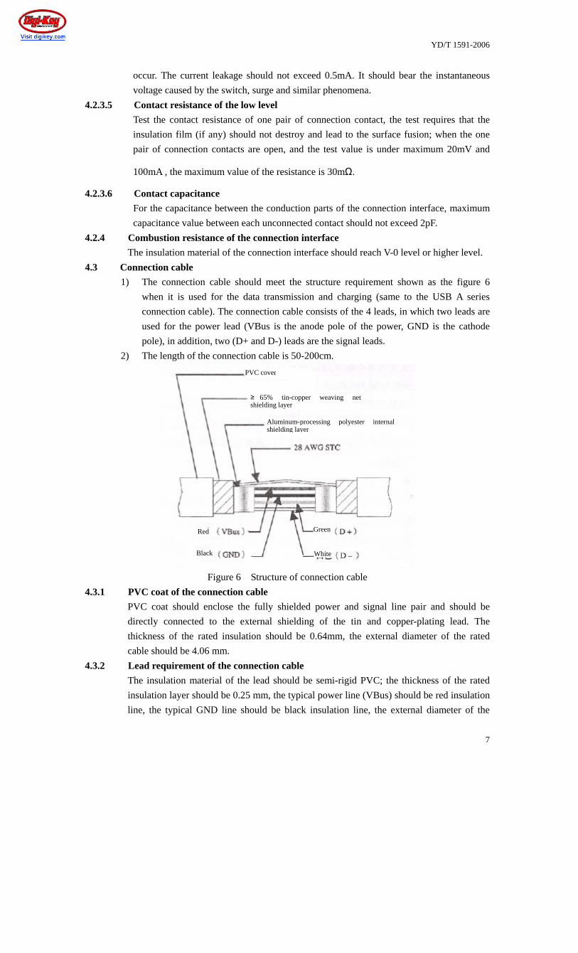
1) The connection cable should meet the structure requirement shown as the figure 6
when it is used for the data transmission and charging (same to the USB A series
connection cable). The connection cable consists of the 4 leads, in which two leads are
used for the power lead (VBus is the anode pole of the power, GND is the cathode
pole), in addition, two (D+ and D-) leads are the signal leads.
2) The length of the connection cable is 50-200cm.
Figure 6 Structure of connection cable
4.3.1 PVC coat of the connection cable
PVC coat should enclose the fully shielded power and signal line pair and should be
directly connected to the external shielding of the tin and copper-plating lead. The
thickness of the rated insulation should be 0.64mm, the external diameter of the rated
cable should be 4.06 mm.
4.3.2 Lead requirement of the connection cable
The insulation material of the lead should be semi-rigid PVC; the thickness of the rated
insulation layer should be 0.25 mm, the typical power line (VBus) should be red insulation
line, the typical GND line should be black insulation line, the external diameter of the
PVC cover
≥ 65% tin-copper weaving net shielding layer
Aluminum-processing polyester internal shielding layer
Red
Black
Green
White

YD/T 1591-2006
8
rated lead is 0.406mm.
4.3.3 Electric performance requirement of the connection cable
The maximum resistance of the lead of the connection cable should be not exceed 0.232Ω
/m.
4.3.4 Combustion resistance of the connection cable
The combustion resistance of the insulation material of the connection cable should reach
V-0 level or higher level.
4.3.5 Recognition of the power supply set
When the terminal detects that the D+ and D- of the interface of the connected power
supply set is under short circuit state, it indicates that the connected set is the charger
defined by this standard. However, it indicates that the connected unit does not belong to
the charger defined by this standard, under this case, the terminal side should start the
current limit measure, and the absorption current should not exceed 500mA.
4.4 Requirement for the charger
4.4.1 Plug and socket on the side of input and output
The input plug of the AC charger should meet the related requirement of the GB2099.1-1996.
If the input end of the charger is the removable power cord, it should meet the requirement
of the GB 5023.5-1997 and GB 17465,1-1998. The output socket should meet the
requirement in the section 4.2 of this standard.
4.4.2 Adaptation scope of the input voltage
The adaptable scope of the input rated AC voltage of the AC charger should be 100-240V,
the capacitance different is ±10%. Under the normal load condition and within the
+10%--10% range of the rated voltage, its stable input current should not exceed the 1.1
times of the rated current and can normally operate.
4.4.3 Adaptable range of the input frequency
The AC charger should be adaptable to power condition of the 50/60 Hz input rated
frequency. Under the normal load condition and within the +10%--10% range of the rated
voltage, its stable input current should not exceed the 1.1 times of the rated current and can
normally operate.
4.4.4 Output voltage
The rated output voltage of the charger should be DC 5V and the capacitance different is
±5%.
4.4.5 Output current
The range of the rated output current of the charger should be 300-1800mA.
4.4.6 Relation between the features of the output voltage and output current (rated current
is 800mA)
The corresponding relation between the output voltage and output current of the charger
meets the requirement of the figure 1 and figure 7.
Table 1 Corresponding relation between the output voltage and output current (rated current is
800mA)
Output voltage Output current
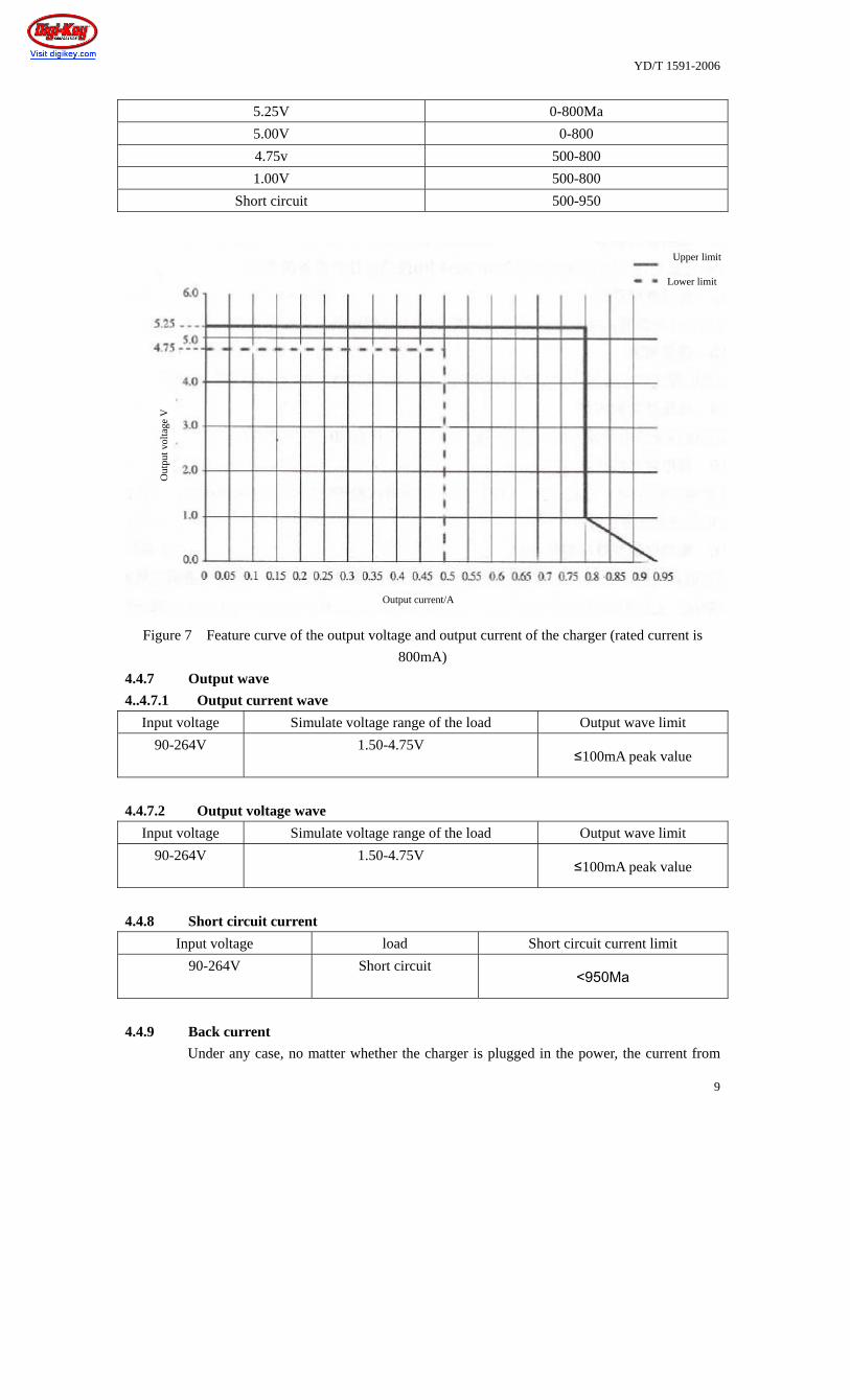
YD/T 1591-2006
9
5.25V 0-800Ma
5.00V 0-800
4.75v 500-800
1.00V 500-800
Short circuit 500-950
Figure 7 Feature curve of the output voltage and output current of the charger (rated current is
800mA)
4.4.7 Output wave
4..4.7.1 Output current wave
Input voltage Simulate voltage range of the load Output wave limit
90-264V 1.50-4.75V ≤100mA peak value
4.4.7.2 Output voltage wave
Input voltage Simulate voltage range of the load Output wave limit
90-264V 1.50-4.75V ≤100mA peak value
4.4.8 Short circuit current
Input voltage load Short circuit current limit
90-264V Short circuit <950Ma
4.4.9 Back current
Under any case, no matter whether the charger is plugged in the power, the current from
Upper limit
Lower limit
Out
put v
olta
ge V
Output current/A

YD/T 1591-2006
10
the terminal side to the charger should not exceed 5mA.
4.4.10 Energy consumption without load
Input voltage Load Power consumption limit
90-264V Open circuit <300Mw
4.4.11 Average power of the charger
The average power of the charger should be less than 50%.
4.4.12 Requirement for output capacitance
The output capacitance range of the charger is recommended to be 150-680 F.
4.4.13 Requirement for magnetic compatibility
4.4.13.1 Requirement for magnetic compatibility under the charging mode of the terminal
When the terminal is under the charging mode, it should meet the corresponding
requirement of the magnetic compatibility standard.
4.4.13.2 Magnetic compatibility requirement for the charger
4.4.13.2.1 Continued emission interference
The emission interference of the charger shell port should meet the requirement of the
class B information technical equipment in GB 9254.
4.4.13.2.2 Continued conduction interference
The conduction interference of the AC power input port of the charger should meet
the requirement of the class B information technical equipment in GB 9254.
4.4.13.2.3 Harmonic wave current
The harmonic wave current of AC power input port of the AC charger should meet the
limit requirement for class A equipment in GB 17625.1.
4.4.13.2.4 Voltage fluctuation and flickering
The voltage fluctuation and flickering of the AC power input port of the AC charger
should meet the requirement of GB 17625.2.
4.4.413.2.5 Interference-resistance of the static discharging
The shell port of the AC charger should pass the static discharging anti-interference
test under the test grade regulated in 5.4.13.2.5. During the test period and after test,
the charger should be able to normally operate.
4.4.13.2.6 Anti-interference of current fast instantaneous pulse cluster
The shell port of the AC charger should pass the anti-interference test of current fast
instantaneous pulse cluster under the test grade regulated in 5.4.13.2.6. During the test,
the charger should keep normal operation, and the level of current fast instantaneous
pulse cluster leaked at the output port of the charger DC power should be less than the
10% of the test level of AC input port. After test, the charger should be able to
normally operate.
4.4.13.2.7 Surge (impact) anti-interference
The AC power input port of the AC charger should pass the surge (impact)
anti-interference test under the test grade regulated in 5.4.13.2.7. During the test and
after test, the charger should be able to normally operate.
4.4.14 requirement for the charger security performance
4.4.14.1 Mechanical intensity
The mechanical intensity of the AC charger should meet the related requirement in GB
YD/T 1591-2006
11
4943-2001.
4.4.14.2 Structure security
The structure security of the AC charger should meet the related requirement in GB
4943-2201.
4.4.14.4 Anti-electric intensity
The first circuit of the AC charger to the second circuit should be able to bear 50Hz or
60Hz, 3000V AC voltage or 4242 DC voltage, the duration is 1 min and no penetration or
flying arc occur.

YD/T 1591-2006
12
4.4.14.5 Contact current
The contact current of the AC charger from AC power to the terminal through the charger
can not exceed 0.25mA.
4.4.14.6 Shock and energy risk
The AC charger should meet the requirement in the related articles in YD 1268.2-2003.
4.4.14.7 Connection cable
The AC charger should meet the requirement in the related articles in YD 1268.2-2003.
4.4.14.8 Temperature increase of the shell surface
The AC charger should meet the requirement in the related articles in YD 1268.2-2003.
4.4.14.9 Short circuit protection of the connection socket
The AC charger should meet the requirement in the standard 4.4.8 and can protect self for
the short circuit; when the failure is eliminated, it should be able to recover the normal
operation.
4.14.10 Requirement for abnormal operation and failure condition
The AC charger should meet the requirement in the related articles in YD 1268.2-2003.
4.4.14.11 Shell combustion resistance
The AC charger requires that the combustion resistance grade of the insulation material
reach the class V-1 or higher class.
4.4.15 Capability requirement for environment adaptability
4.4.15.1 Low temperature
4.4.15.1.1 Low temperature storage
The AC charger is stored for 16h under the (-40±3)0C, After it is recovered under the
normal gas pressure condition, the mechanical structure is not damaged, the electric
performance should meet the requirement of 4.4.4, 4.4.5, 4.4.7 and 4.4.14.4.
4.4.15.1.5 low-temperature operation
After the AC charger is tested for 2 h under the operation state (-10±3)0C, the
electric performance should meet the requirement in 4.4.4, 4.4.5 and 4.4.7.
4.4.15.2 High temperature
4.4.15.2.1 High temperature storage
After the AC charger is stored for 16 h under the (70±3)0C and is recovered under the
normal air pressure, the mechanical structure should not be damaged, the electric
performance should meet the requirement in 4.4.4, 4.4.5, 4.4.7 and 4.4.14.4.
4.4.15.2.2 High temperature operation
After the AC charger is stored for 2h under the (40±3)0C, the electric performance
should meet the requirement in 4.4.4, 4.4.5 and 4.4.7.
4.4.15.3 Humidity heat
After the AC charger passes the environment test of (40±2)0C and relative humidity
93+2% -3%, the mechanical structure should not be damaged, the electric performance
should meet the requirement in 4.4.4, 4.4.5, 4.4.7 and 4.4.14.4.

YD/T 1591-2006
13
4.4.15.4 Vibration
After the AC charger passes the frequency 10-55Hz placement and 0.35 scanning
frequency and vibration, the mechanical structure should not be damaged, the electric
performance should meet the requirement in 4.4.4, 4.4.5, 4.4.7 and 4.4.14.4.

YD/T 1591-2006
14
4.4.15.6 Falling
After the AC charger falls to the concrete surface from the (10±0.10)m height, except for
the surface erosion, the mechanical structure should not be loosened or damaged, it
should be able to normally operate.
4.4.16 Identification requirement
4.4.16.1 Nameplate flag
The nameplate of the AC charger should include the following contents:
Input and output rated voltage value V (unit)
Input and output rated current value mA or A (unit)
Rated frequency of AC charger Hz (unit)
The power nature should meet (only for DC) ------
Manufacturer name or trademark or mark
Type regulated by the manufacturer
“Back” character, only proper for class II equipment
4.4.16.2 Endurance of nameplate
The AC charger nameplate be endurable and remarkable, and should meet the related
requirement in the GB 4943-2001.
5 Test method
5.1 Test requirement
The test point on the terminal side should be measured at the connection plug position and
should connect the connection cable reliably to the terminal.
5.2 Test of the connection interface
5.2.1 Mechanical structure test of the connection interface
Measure whether the mechanical structure of the plug and socket meets the requirement
through the measure which precision is not less than 0.005mm.
5.2.2 Reliability test of the connection interface
5.2.2.1 Test for plug-in force and plug-out force
Fix the plug on the clamp, and the plug is connected to the force meter in rigid manner.
The plug should be inserted into the socket at the speed not less than 12.5mm/min till it is
fully inserted, the test should be repeated for 5 times, the average of the maximum values
in each test is the test result of the plug-in force. After the plug is fully connected to the
socket, give the pulling force on the plug and gradually increase the pulling on the plug
till the plug is separated from the socket, the test should be repeated for 5 times, the
average of the maximum value in each test is the test result for the plug-out force.
5.2.2.2 Test for plug lifetime
Respectively fix the plug and socket on the special equipment repeatedly, the frequency
should not exceed 200 periods in one hour, total 1500 periods of plug are implemented,
after the plugging terminates, it is tested by using the test method regulated in 5.2.2.1 and
5.2.3.
5.2.4 Electric performance test of the connection interface
5.2.3.1 Electric performance test of connection interface on the terminal side
YD/T 1591-2006
15
During test, the tested terminal is under the maximum charging load condition.
(1) Check the charging voltage and current mark or explanation of the terminal; the
simulated charger power set and amperemeter which rated voltage is 5 V and
maximum output power is 10W, and power changes with the load are connected to
the terminal for 20 min, observe the maximum absorption current of the terminal,
meanwhile, observe whether the phenomena such as over heat, combustion,
explosion and other circuit damages occur and whether the terminal can normally
operate.
(2) Use the adjustable and constant-voltage simulation charger and amperemeter to
connect to the terminal, the adjustable value is from 4V to the deign value of the
secure protection voltage of the product. Observe whether the protection set has
action and voltage value upon action, and next stop at the designed value of the
secure protection voltage of the product for 60min, meanwhile, the surface
temperature of the terminal is monitored and observe whether the phenomena the
overheat, combustion, explosion and other circuit damage occur, and whether the
terminal can normally operate.
(3) Use the simulation set and amperemeter meeting USB specification (USB A series)
to connect to the terminal, observe and measure the charging absorption current of
the terminal.
(4) Check the related flag or explanation of the terminal.
5.2.3.2 Interface test of the charger
(1) Check whether the anode and cathode of the interface on the charger side is correct,
check whether D+ and D- is short circuit and test whether the D+ or D- and VBus
line, ground line and other charger circuits are insulated.
(2) Check whether the related normal voltage and current marked by the charger is
correct
5.2.3.3 Test for the insulation resistance
Respectively use the DC 500V and 1000V test voltage to measure insulation resistance of
each insulation layer.
The insulation resistance should be measured between the nearest contacts, and between
the plug and socket shell, or between bottom plate and nearest contact. Under each case,
it is tested for 6 times (3 adjacent contacts and/or 3 contacts connecting to the shell
and/or 3 contacts connecting to the bottom plate), the resistance takes the value of the
minimum limit or the larger part of the 10% of all contacts. When the insulation
resistance is tested, each time same contact area of a given plug and socket should be
used.
The test duration is 1 min, the minimum value in the test is recorded as the test result.
When the current condition has influences on the insulation feature of the insulation
resistance, the insulation test should be instantly tested within 2 min after the current is
released.
5.2.3.4 Voltage endurance test of the insulation material
The test voltage increases from 0 to 500V at the 500V/s speed and the keep 1 min at this
voltage.
a) The test voltage should be imposed between the nearest interval contacts or contact

YD/T 1591-2006
16
between the shell of the plug and socket and nearest shell.
b) The test voltage should be imposed between the adjacent contacts.
c) The test voltage should be imposed on each contact alternately, all other contacts and
shell should be connected together.
During the voltage endurance test, the error and current leakage indicator should be
monitored as the evidence of the cracking discharging and current leakage. The
tested sample should be checked and measured to identify the effect of the voltage
endurance of the current media under the special work feature, observe whether the
phenomena the penetration, flame and flying arc occur, whether the leaked current
exceeds 0.5mA.
5.2.3.5 Contact resistance test of the low level
Use a 4-line micro-ohm meter. This micro-ohm meter should adopt a method to correct
the thermal current magnetic field. This test method includes the AC, pulse DC or current
return. Generally the integrated micro-ohm meter measures the practical test current and
voltage drop of the tested sample. The measured resistance is computed internally and
displayed.
5.2.3.6 Test for the contact capacitance
The capacitance should be tested under the following configuration at the defined
frequency.
The lowest impedance path is used to connect to the ground between one contact and the
ground including the following several parts.
- All other contacts;
- All metal part
- Bottom plate
The following part will be connected to the ground at a common point between two any
adjacent contacts:
- All other contacts
- All metal part
- Bottom plate
5.2.4 Combustion test of the connection interface
Test in accordance with the method in the appendix A of GB 4943-2001.
5.3 Test of the connection cable
(1) Check whether the ranking sequence of the contacts at both ends of the connection
cable is correct.
(2) Adopt the length measure tool to measure the length of the connection cable.
5.3.1 PVC coat test of the connection cable
Adopt the length measure tool and special measure to text whether the mechanical
structure of the connection cable meet the requirement.
5.3.2 Test of the connection cable
Adopt the length measure tool and special measure to text whether the mechanical
structure of the connection cable meet the requirement.
5.3.3 Electric performance test of the connection cable
Use the impedance analyzer or resistance meter to respectively measure the resistance
between each corresponding end of the connection cable.

YD/T 1591-2006
17
5.3.4 Combustion test of the connection cable
Test in accordance with the method in the appendix A of GB 4943-2001.
5.3.5 Recognition test of the power supply set
Connect the set and amperemeter which output voltage is 5V and output current is higher
than 500mA and meet the USB A series interface specification with the terminal to observe
the value of the absorption current.
Connect the charger and amperemeter which output voltage is 5V and output current is
higher than 500mA to observe the value of the absorption current.
5.4 Test of the charger
5.4.1 Test for the plug and socket at the input and output end
Check whether the plug and socket at the input and output end meet.
5.4.2 Test of adaptable range of the input voltage
Under the normal load condition of the tested equipment, test the equipment when the
input voltage is within +10%--10% range of the rated voltage.
If the equipment has a rated voltage, the input current should be tested at this rated
voltage.
If the equipment has a rated voltage range, the input current should be tested at any end
voltage within the rated voltage range.
The higher input current measured within the related voltage range should be used for
judgement.
Under each case, read when the input current keeps stable.
5.4.3 Test of the adaptation range of the input frequency
Under the normal load condition of the tested equipment, test the equipment when the
input voltage is within +10%--10% range of the rated voltage.
If the equipment has two frequencies, the input is tested at two frequencies.
The higher input current measured within the related voltage range should be used for
judgement.
Under each case, read when the input current keeps stable.
5.4.4 Test of output voltage
Connect the simulated load with the tested charger, adjust the impedance of the simulated
load and monitor the output voltage.
5.4.5 Test of the output current
Connect the simulated load with the tested charger, adjust the impedance of the simulated
load and monitor the output voltage.
5.4.6 Test of the feature relation of the output voltage and output current
Connect the simulated load with the tested charger, adjust the impedance of the simulated
load and monitor the output voltage and output current.
5.4.7 Test of the output wave
Input the voltage regulated in the 4.4.7 at the input end of the tested charger, the input end
is connected to the simulated load, adjust the simulated load, use the oscillograph to
measure the output wave of the tested charger and record the maximum peak value.
5.4.8 Test of the short circuit current
Adjust simulated load resistance of the charger to 0Ω, meanwhile, monitor the loop current

YD/T 1591-2006
18
and record it.
5.4.9 Test of the back current
Continually adjust the simulated power from 0V to 5V and monitor the stable current to
the charger. Notice that when the power supply is adjusted, the power energy caused by
the output end capacitance of the flow-in or flow-out charger can not be calculated as the
stable current. The test method is shown as the figure 8.
Figure 8 Connection of the back current test
5.4.10 Test of non-load energy consumption
Use the power meter to measure the power and record when the charger is under the non
load state.
5.4.11 Test of the average charger power
Under the testing condition of the heated machine, the input voltage is set as 220V, adjust
the simulated load to respectively test the charger efficiency when the load current is
respectively under 100%, 75%, 50% and 25% of the rated output current, next takes their
average value.
Efficiency =DC output efficiency/AC input active power=Uolo/Pix100%
In this equation:
Uo: load voltage (V)
Io: load current (A)
Pi: the AC input active power of the current-adjusting equipment(W), the active power is
the visual power is multiplied by the power factor. The input voltage is multiplied by the
input current to get the visual power. The power meter can read the power factor, or
directly read the input power.
Figure 9 Test connection of the average charger power
5.4.12 Test of the output capacitance
The test of the output capacitance is considered when the charger designer designs it.
5.4.13 Test of magnetic compatibility
5.4.13.1 Test for the magnetic compatibility under the charging mode on the terminal side
5.4.13.1.1 Introduction
Power supply
Power
Return current of the charger
Simulation
Power
Connection socket
Charger
Pow
er supply
Pow
er meter
Charger
Load
YD/T 1591-2006
19
When the magnetic compatibility is tested under the charging mode on the terminal
side, the auxiliary DC power should be used to charge the terminal side, the electric
performance of the auxiliary DC power supply should meet the requirement in the
article 5.4.13.1.2.
When the magnetic interference is tested, the DC power port on the terminal side
should be connected to the auxiliary DC power through the manual power network, so
it can avoid that the auxiliary DC power affects the measure results of the magnetic
interference of the terminal. In accordance with the requirement in GB 9254, the
proper power network should be selected.
When the anti-interference is tested, he DC power port of the terminal should be
connected to the auxiliary DC power through the de-coupling network, so it can avoid
that the auxiliary DC power affects the measure results of the anti-interference of the
terminal. In accordance with test requirement for anti-interference, the proper
de-coupling network should be selected.
5.4.13.1.2 The electric performance of the auxiliary DC power
The electric performance of the auxiliary DC power should meet the following
requirements:
(1) The output voltage should be 5V, the capacitance different ±2%
(2) The maximum output current is not less than 2000Ma, the capacitance different
±2%;
(3) The output ripple meets the requirement in the article 4.4.7.
5.4.13.2 Test of the magnetic compatibility of the charger
5.4.13.2.1 Measure of the continual emission interference
Measure the emission interference of the shell port of the charger in according with
the standard GB 9254. Upon measure, the charger should be connected to the
simulated load to make the charger operate under the maximum power mode. The
electric performance of the simulated load should meet the requirement in the article
5.4.13.2.9.
5.4.13.2.2 Measure of the continual conduction interference
Measure the continual conduction interference of the power port of the charger in
according with the standard GB 9254. Upon measure, the charger should be connected
to the simulated load to make the charger operate under the maximum power mode.
The electric performance of the simulated load should meet the requirement in the
article 5.4.13.2.9.
5.4.13.2.3 Measure of the harmonic wave
Measure the harmonic wave current of the AC power input port of the charger in
according with the standard GB 17625.1. Upon measure, the charger should be
connected to the simulated load to make the charger operate under the maximum
power mode. The electric performance of the simulated load should meet the
requirement in the article 5.4.13.2.9.
5.4.13.2.4 Measure of voltage fluctuation and flickering
Measure the voltage fluctuation and flickering of the AC power input port of the
YD/T 1591-2006
20
charger in according with the standard GB 17625.2. Upon measure, the charger
should be connected to the simulated load to make the charger operate under the
maximum power mode. The electric performance of the simulated load should meet
the requirement in the article 5.4.13.2.9.
5.4.13.2.5 Test of the static discharging anti-interference
Test the static discharging anti-interference on the shell port of the charger in
accordance with the standard GB/T 17626.2.
The test class is:
(1) test level of the contact discharging is ±2kV and ±4kV.
(2) The test level of the air discharging is ±2kV, ±4kV and ±8kV.
The charger should be tested under the following two modes:
(1) Maximum power mode: the output port of the charger is connected to the
simulated load under the maximum power mode, the electric performance of the
simulated load should meet the requirement in 5.4.13.2.9.
(2) Backup mode: the charger is not connected to the AC or DC power network and
other loads.
5.4.13.2.6 Test of the current fast instantaneous pulse cluster anti-interference
Test the current fast instantaneous pulse cluster anti-interference of the power input
port of the AC charger in accordance wit the GB/T 17626.4. The test level is 2kV.
Upon test, the charger should be connected to the simulated load to make the charger
operate under the maximum power mode. The electric performance of the simulated
load should meet the requirement in the article 5.4.13.2.9.
Use the auxiliary monitoring equipment to measure the pulse cluster level of the DC
output port of the charger.
5.4.13.2.7 Test of surge (impact) anti-interference
Test the surge (impact) anti-interference of the power input port of the AC charger in
accordance with the GB/T 17626.5.
The test class is:
(1) The line-to-line test level is 1kV.
(2) The line-to-ground test level should be 2kV
(3) The test wave is 1.2/50μs.
Upon test, the charger should be connected to the simulated load to make the charger
operate under the maximum power mode. The electric performance of the simulated
load should meet the requirement in the article 5.4.13.2.9.
5.4.13.2.8 Electric performance of the simulated load
The simulated load should be pure-resistance resistance, its electric parameters should
meet the regulation in the table 2.
Table 2 Electric parameters of the simulated load
Rated output current of
the charger
Resistance of the simulated
load
Capacitance different of
simulated load resistance
Rated power of the
simulated load

YD/T 1591-2006
21
800Ma 6.25Ω ±10%
Not less than 10W
Other Compute the resistance in
accordance with the
equation (1)
±10% Not less than 10W
The resistance of he simulated load=rated output voltage of the charger/rated output current of the
charger
5.4.14 Test of the security performance of the charger
5.4.14.1 Test of the mechanical intensity
5.4.14.1.1 Test of the constant action
Test in accordance with the testing method for the constant action test in the GB
4923-2001.
5.4.14.1.2 test of the torque of the direct plug-in equipment
Test in accordance with the testing method for the direct plug-in equipment in the GB
4923-2001.
5.4.14.2 Structure test
Test in accordance with the testing method regulated in the GB 4923-2001.
5.4.14.3 Insulation resistance
Test the insulation resistance in accordance with the testing method regulated in the GB
1268.2-2003.
5.4.14.4 Anti-current intensity
After the insulation resistance is tested in the article 5.4.14.3, test in accordance with the
testing method regulated in the anti-current intensity of the GB 4923-2001.
5.4.14.5 Contact current
Test in accordance with the testing method regulated in the YD 1268.2-2003.
5.4.14.6 Shock and energy risk
Test in accordance with the testing method regulated in the YD 1268.2-2003.
5.4.14.7 Connection layout
Test in accordance with the testing method regulated in the YD 1268.2-2003.
5.4.14.8 Test of the temperature increase of the shell surface
Test in accordance with the testing method regulated in the YD 1268.2-2003.
5.4.14.9 Test of the short-circuit protection of the connection socket
The AC charger is under the maximum rated voltage and makes the power end and
grounding end be short at the output port of the connection socket. Check whether the
charge can protect itself. After the failure is eliminated, electrify again under the non-load
state and check whether it can automatically recover to operation
5.4.14.10 Test under the abnormal operation and failure condition
Test in accordance with the testing method regulated in the YD 1268.2-2003.
5.4.14.11 Test of the combustions resistance of the charger shell
Test in accordance with the testing method regulated in the appendix A of the GB
4923-2001.
5.4.5 Test of the environment adaptability
5.4.15.1 Low temperature
YD/T 1591-2006
22
5.4.15.1.1 Low temperature storage
The tested sample is placed into the low temperature test box without any packing.
Start the temperature box, make the temperature inside the box gradually reduce to be
-400C at the average speed less than 10C/min, after the tested sample keeps the stable
temperature for 16h, take out the tested sample and place it under the standard test
condition for 2h, next make the test in the 5.4.4, 5.4.5, 5.4.7 and 5.4.14.4.
YD/T 1591-2006
23
5.4.15.1.2 Low temperature operation
The tested sample is placed into the low temperature test box without any packing.
Start the temperature box, make the temperature inside the box gradually reduce to be
-100C at the average speed less than 10C/min, keep this temperature till the tested
sample reaches the stable temperature, the tested sample starts to operate, after 2 h,
make the test in the 5.4.4, 5.4.5 and 5.4.7.
5.4.15.2 High temperature
5.4.15.2.1 High temperature storage
The tested sample is placed into the low temperature test box without any packing.
Start the temperature box, make the temperature inside the box gradually increase to
be 700C at the average speed less than 30C/min, after the tested sample keeps the
stable temperature for 16h, take out the tested sample and place it under the standard
test condition for 2h, next make the test in the 5.4.4, 5.4.5, 5.4.7 and 5.4.14.4.
5.4.15.2.2 High temperature operation
The tested sample is placed into the low temperature test box without any packing.
Start the temperature box, make the temperature inside the box gradually increase to
be -400C at the average speed less than 30C/min, keep this temperature till the tested
sample reaches the stable temperature, the tested sample starts to operate, after 2 h,
make the test in the 5.4.4, 5.4.5 and 5.4.7.
5.4.15.3 Humid heat
The tested sample is placed into the test box without any packing, switch on the power of
the humid heat box to make the temperature inside the box increase to be 400C, next,
increase the humidity and mix the air inside the box, when the temperature meets the
requirement and the relative humidity is between 90% and 95%, keep it for 48 h, next
make the test in the 5.4.4, 5.4.5, 5.4.7 and 5.4.14.4.
5.4.15.4 Vibration
The tested is fixed on the vibration table. Within the frequency 10Hz to 55Hz range, the
amplitude is 0.35mm, scan for the 5 times along the three axis direction, the test time of
each axis is 25 min, after the test ends, make the test in the 5.4.4, 5.4.5, 5.4.7 and
5.4.14.4.
5.4.15.5 Impact
The tested sample is fixed on the impact table without any packing, the sample should be
installed according to the requirement in the GB/T 2423.43. the tested sample keeps
semi-sine pulse for 18ms at the peak acceleration 300m/s2, impose the 3 times of the
continual impacts along each direction of the 3 mutually vertical axis, namely total time
is 18 times, after the test ends, make the test in the 5.4.4, 5.4.5, 5.4.7 and 5.4.14.4.
5.4.15.6 Falling
Place the tested sample at the plane with the height (1.0±0.10) m without any packing
and make freely fall to the concrete ground, fall for two times on each side, total 12 times
are for 6 sides, after the test ends, observe the appearance and check the function.
5.4.16 Mark test
Test in accordance with the testing method regulated in the GB 4923-2001.